

Minarik Drives VFD SERIES Users Manual

VFD01-230AC VFD01-230AC-PCM
VFD01-D230AC VFD01-D230AC-PCM
VFD02-115AC VFD02-115AC-PCM
VFD02-230AC VFD02-230AC-PCM
VFD02-D230AC VFD02-D230AC-PCM
VFD04-115AC VFD04-115AC-PCM
VFD04-230AC VFD04-230AC-PCM
VFD04-D230AC VFD04-D230AC-PCM
USER’S MANUAL
VFD SERIES
Variable-frequency drives
for 3-phase and single-phase
AC motors

Copyright © 2002 by
Minarik Corporation
All rights reserved. No part of this manual may be reproduced or transmitted in any
form without written permission from Minarik Corporation. The information and
technical data in this manual are subject to change without notice. Minarik
Corporation and its Divisions make no warranty of any kind with respect to this
material, including, but not limited to, the implied warranties of its merchantability
and fitness for a given purpose. Minarik Corporation and its Divisions assume no
responsibility for any errors that may appear in this manual and make no
commitment to update or to keep current the information in this manual.
MVD082602
Printed in the United States of America.

i
Safety Warnings
• This symbol denotes an important safety tip or
warning. Please read these instructions carefully
before performing any of the procedures contained in
this manual.
• DO NOT INSTALL, REMOVE, OR REWIRE THIS
EQUIPMENT WITH POWER APPLIED. Have a qualified
electrical technician install, adjust and service this
equipment. Follow the National Electrical Code and all
other applicable electrical and safety codes, including the
provisions of the Occupational Safety and Health Act
(OSHA), when installing equipment.
• Reduce the chance of an electrical fire, shock, or
explosion by using proper grounding, over-current
protection, thermal protection, and enclosure. Follow
sound maintenance procedures.
It is possible for a drive to run at full speed as a result of
a component failure. Minarik strongly recommends the
installation of a master switch in the main power input to stop
the drive in an emergency.
Circuit potentials are at 115 VAC or 230 VAC above earth
ground. Avoid direct contact with the printed circuit board or
with circuit elements to prevent the risk of serious injury or
fatality. Use a non-metallic screwdiver for adjusting the
calibration trimpots. Use approved personal protective
equipment and insulated tools if working on this drive with
power applied.
SHOCKAVOID
OID
ON
TI

ii
The Minarik Variable Frequency Drive (VFD) Series are
solid-state, variable-frequency AC motor drives. The VFD
utilizes a 115 or 230 VAC, 50/60 Hz, single-phase input,
and is factory calibrated for an output of 0 to 60 Hz. They
will operate any 1 HP or smaller, 115 or 208/230-volt, threephase-AC-induction, single-phase permanent split capacitor
motor (see page v) and can be user calibrated for 0 through
120 Hz output.
Although VFD inverters can operate over their full speed
range, most motors will operate with constant torque over a
10:1 speed range, 6 Hz to 60 Hz, and constant horsepower
above 60 Hz. (Inverter-duty motors may operate
satisfactorily over a 20:1 speed range.) Some motors can
be satisfactorily operated at speeds as low as 50 rpm
(speed range 50:1). Below 50 rpm, some motors may
show signs of “stepping” or “cogging”, and may run warmer.
*Although the VFD will allow a minimum of 0 Hz, the actual minimum
frequency is dependent on motor type and load. The motor may need to be
derated for low-frequency (30 Hz and lower) operation. Please consult the
motor manufacturer.
General Information

iiiGeneral Information
Many 3-phase inverter manufacturers claim that they can
run single-phase motors effectively. This is normally
accomplished by wiring only 2 phases; however, this
method may cause instabilities due to the lack of feedback
from one of the motor connections. Furthermore, motor
torque will be reduced considerably because the phases
are 120° apart. Although the VFD uses this method of
connection, its fundamental design enables it to operate
efficiently under these conditions.
The VFD series features solid-state reversing with
adjustable acceleration and deceleration. The VFD may
also interface with motor thermal protection through the
enable circuit.
iv General Information
Figure 1. VFD Series Features & Benefits
VFD SERIES FEATURES & BENEFITS
• SOLID-STATE CIRCUITRY
• SOLID-STATE REVERSING
• ADJUSTABLE CARRIER FREQUENCY (4 kHz - 16 kHz)
• MULTIPLE MOTOR OPERATION
• THREE-PHASE AND SINGLE-PHASE MOTOR CONTROL
VUW
LED INDICATORS
POWER
(green)
FAULT
(red)
TORQUE
(yellow)
SET
321
TB501
ZERO
4 mA
DECEL
ACCEL
JMP501:INPUT RANGE
2:0-10VDC
1:0-5VDC
3:4-20MA
JMP502
S1S2S3
E2
E1
ACCEPTS A 0 - 5 VDC,
0 - 10 VDC, or 4 - 20 mA
NON-ISOLATED SIGNAL
OPTIONAL ISOLATION BOARD
TH501
BOO
TQ
TQ
C501
L2
ADJUSTABLE
CALIBRATION
TRIMPOTS
DECEL
C502
JMP502:INPUT TYPE
2-3:CURRENT
1-2:VOLTAGE
TB501
D
J501
115V230V
L1
ACCEL
MAX
BOOST
TQ LIMIT
DOUBLES THE OUTPUT
VOLTAGE TO THE AC
MOTOR WHEN 115 IS APPLIED
optional
ZERO SET
on isolation board
DOUBLER VERSIONS

v
In addition to standard 3-phase induction motors, the
following motor types may be used with the VFD:
• Permanent split capacitor (PSC)
• Shaded pole
• AC synchronous
Warning
Caution should be taken when operating fan-cooled
motors at low speeds because their fans may not
move sufficient air to properly cool the motor. Minarik
recommends “inverter-duty” motors when the speed
range is beyond 10:1.
The following motor types MAY NOT be used:
• Split phase
• Capacitor start
• Repulsion induction
• Series Universal AC/DC
• Any motor with starting switch (centrifugal or relay)
and/or separate starting winding.
Important Information

vi
Contents
Safety Warnings i
General Information ii
Important Information v
Specifications 1
Dimensions 2
Installation 10
- PCM Isolation Option Board Mounting . . . . . . . . . . . . . . . . . . . . . . . . . . . . . .10
Mounting . . . . . . . . . . . . . . . . . . . . . . . . . . . . . . . . . . . . . . . . . . . . . . . . . . . . . .15
Wiring . . . . . . . . . . . . . . . . . . . . . . . . . . . . . . . . . . . . . . . . . . . . . . . . . . . . . . . . .17
Shielding guidelines . . . . . . . . . . . . . . . . . . . . . . . . . . . . . . . . . . . . . . . . . . .18
Heat sinking . . . . . . . . . . . . . . . . . . . . . . . . . . . . . . . . . . . . . . . . . . . . . . . . . . .19
Fusing . . . . . . . . . . . . . . . . . . . . . . . . . . . . . . . . . . . . . . . . . . . . . . . . . . . . . . . .20
Speed adjust potentiometer . . . . . . . . . . . . . . . . . . . . . . . . . . . . . . . . . . . . . . . .21
Connections . . . . . . . . . . . . . . . . . . . . . . . . . . . . . . . . . . . . . . . . . . . . . . . . . . . .22
Power and fuse connections . . . . . . . . . . . . . . . . . . . . . . . . . . . . . . . . . . . .22
Motor connections (all VFD-series controls) . . . . . . . . . . . . . . . . . . . . . . . .27
Speed Adjust Potentiometer Connections . . . . . . . . . . . . . . . . . . . . . . . . . .31
Voltage Follower Connections . . . . . . . . . . . . . . . . . . . . . . . . . . . . . . . . . . .32
Signal and Optional Switch Connections . . . . . . . . . . . . . . . . . . . . . . . . . . .33
Voltage or Current Follower (-PCM models) . . . . . . . . . . . . . . . . . . . . . . . .35
Operation 37
Voltage Doubler . . . . . . . . . . . . . . . . . . . . . . . . . . . . . . . . . . . . . . . . . . . . . . . . .38
Startup . . . . . . . . . . . . . . . . . . . . . . . . . . . . . . . . . . . . . . . . . . . . . . . . . . . . . . . .39
To reverse motor direction: . . . . . . . . . . . . . . . . . . . . . . . . . . . . . . . . . . . . .40
Starting and stopping methods . . . . . . . . . . . . . . . . . . . . . . . . . . . . . . . . . . . . .41
To coast the motor to a stop . . . . . . . . . . . . . . . . . . . . . . . . . . . . . . . . . . . .41
Thermal protection of the motor . . . . . . . . . . . . . . . . . . . . . . . . . . . . . . . . . .41
Line starting and line stopping . . . . . . . . . . . . . . . . . . . . . . . . . . . . . . . . . . .43

viiContents
Calibration 44
Calibration Procedure Setup for 60 Hz Motors: . . . . . . . . . . . . . . . . . . . . . . . .46
MAXIMUM SPEED (MAX SPD) . . . . . . . . . . . . . . . . . . . . . . . . . . . . . . . . . .46
TORQUE LIMIT (TQ LIMIT) . . . . . . . . . . . . . . . . . . . . . . . . . . . . . . . . . . . . .47
ACCELERATION (ACCEL) . . . . . . . . . . . . . . . . . . . . . . . . . . . . . . . . . . . . .48
DECELERATION (DECEL) . . . . . . . . . . . . . . . . . . . . . . . . . . . . . . . . . . . . .48
BOOST . . . . . . . . . . . . . . . . . . . . . . . . . . . . . . . . . . . . . . . . . . . . . . . . . . . . .49
Calibration Procedure Conclusion . . . . . . . . . . . . . . . . . . . . . . . . . . . . . . . .50
Application Notes 51
Independent adjustable speeds with DIR switch . . . . . . . . . . . . . . . . . . . . . . .51
RUN/JOG switch . . . . . . . . . . . . . . . . . . . . . . . . . . . . . . . . . . . . . . . . . . . . . . . .52
Single speed potentiometer control of multiple motors . . . . . . . . . . . . . . . . . . .53
Quick Reversing . . . . . . . . . . . . . . . . . . . . . . . . . . . . . . . . . . . . . . . . . . . . . . . . .54
Troubleshooting 55
Before troubleshooting . . . . . . . . . . . . . . . . . . . . . . . . . . . . . . . . . . . . . . . . . . .55
Diagnostic LEDs . . . . . . . . . . . . . . . . . . . . . . . . . . . . . . . . . . . . . . . . . . . . . . . .57
POWER LED . . . . . . . . . . . . . . . . . . . . . . . . . . . . . . . . . . . . . . . . . . . . . . . .57
FAULT LED . . . . . . . . . . . . . . . . . . . . . . . . . . . . . . . . . . . . . . . . . . . . . . . . .57
TQ LIMIT LED . . . . . . . . . . . . . . . . . . . . . . . . . . . . . . . . . . . . . . . . . . . . . . .58
Optional C510 Capacitor Kit (p/n: 202-0108) . . . . . . . . . . . . . . . . . . . . . . . . . .63
Replacement Parts . . . . . . . . . . . . . . . . . . . . . . . . . . . . . . . . . . . . . . . . . . . . . .65
Unconditional Warranty 67
Tables
Table 1. Line Fusing Chart . . . . . . . . . . . . . . . . . . . . . . . . . . . . . . . . . . . . . . . . . . . . . . . . . . . . .20
Table 2. Replacement Parts . . . . . . . . . . . . . . . . . . . . . . . . . . . . . . . . . . . . . . . . . . . . . . . . . . . .65

viii
Illustrations
Figure 1. VFD Series Features & Benefits . . . . . . . . . . . . . . . . . . . . . . . . . . . . . . . . . . . . . . . . . .iv
Figure 2. VFD01-230AC, VFD02-115AC, VFD02-230AC Dimensions . . . . . . . . . . . . . . . . . . . . .2
Figure 3. VFD04-115AC and VFD04-230AC Dimensions . . . . . . . . . . . . . . . . . . . . . . . . . . . . . . .3
Figure 4. VFD01-230AC-PCM, VFD02-115AC-PCM
and VFD02-230AC-PCM Dimensions . . . . . . . . . . . . . . . . . . . . . . . . . . . . . . . . . . . . . .4
Figure 5. VFD04-115AC-PCM and VFD04-230AC-PCM Dimensions . . . . . . . . . . . . . . . . . . . . .5
Figure 6. VFD01-D230AC & VFD02-D230AC Dimensions . . . . . . . . . . . . . . . . . . . . . . . . . . . . . .6
Figure 7. VFD04-D230AC Dimensions . . . . . . . . . . . . . . . . . . . . . . . . . . . . . . . . . . . . . . . . . . . . .7
Figure 8. VFD01-D230AC-PCM and VFD02-D230AC-PCM Dimensions . . . . . . . . . . . . . . . . . . .8
Figure 9. VFD04-D230AC-PCM Dimensions . . . . . . . . . . . . . . . . . . . . . . . . . . . . . . . . . . . . . . . .9
Figure 10. VFD Series Drive with PCM adder board & -PCM adder kit . . . . . . . . . . . . . . . . . . .11
Figure 11. Speed Adjust Potentiometer . . . . . . . . . . . . . . . . . . . . . . . . . . . . . . . . . . . . . . . . . . . .21
Figure 12. AC Line and Fuse Connections for VFDxx-115AC and
VFDxx-230AC Series Drives . . . . . . . . . . . . . . . . . . . . . . . . . . . . . . . . . . . . . . . . . . .23
Figure 13. AC Line and Fuse Connections for VFDxx-D230AC Series Drives
(Voltage Doubler Mode) . . . . . . . . . . . . . . . . . . . . . . . . . . . . . . . . . . . . . . . . . . . . . . .25
Figure 14. AC Line and Fuse Connections for VFDxx-D230AC Series Drives
(No Voltage Doubler) . . . . . . . . . . . . . . . . . . . . . . . . . . . . . . . . . . . . . . . . . . . . . . . . .26
Figure 15. Motor Connections for Single-Phase Operation
(Motor With Pre-Wired Capacitor) . . . . . . . . . . . . . . . . . . . . . . . . . . . . . . . . . . . . . . .28
Figure 16. Motor Connections for Single-Phase Operation
(Configured for use with DIRECTION switch) . . . . . . . . . . . . . . . . . . . . . . . . . . . . . .29
Figure 17. Motor Connections for Three-Phase Motors . . . . . . . . . . . . . . . . . . . . . . . . . . . . . . .30
Figure 18. Speed Adjust Potentiometer Connections to TB501 . . . . . . . . . . . . . . . . . . . . . . . . .31
Figure 19. Voltage Follower connections . . . . . . . . . . . . . . . . . . . . . . . . . . . . . . . . . . . . . . . . . .32
Figure 20. Enable / Disable Switch connections to TB501 . . . . . . . . . . . . . . . . . . . . . . . . . . . . .33
Figure 21. Signal and Optional Switch Connections . . . . . . . . . . . . . . . . . . . . . . . . . . . . . . . . . .34
Figure 22. -PCM jumper locations and terminal connections . . . . . . . . . . . . . . . . . . . . . . . . . . .36
Figure 23. Thermal Overload Switch with Optional Enable / Disable Switch . . . . . . . . . . . . . . .42
Figure 24. VFD Series Calibration Trimpot Layout . . . . . . . . . . . . . . . . . . . . . . . . . . . . . . . . . . .45
Figure 25. Independent Adjustable Speeds . . . . . . . . . . . . . . . . . . . . . . . . . . . . . . . . . . . . . . . . .51
Figure 26. RUN/JOG Switch . . . . . . . . . . . . . . . . . . . . . . . . . . . . . . . . . . . . . . . . . . . . . . . . . . . .52
Figure 27. Single Speed Potentiometer Control of Multiple Motors . . . . . . . . . . . . . . . . . . . . . .53
Figure 28. VFD Quick Reversing . . . . . . . . . . . . . . . . . . . . . . . . . . . . . . . . . . . . . . . . . . . . . . . . .54
Figure 29. VFD Series diagnostic LED locations . . . . . . . . . . . . . . . . . . . . . . . . . . . . . . . . . . . .58
Figure 30. Carrier frequency capacitor location . . . . . . . . . . . . . . . . . . . . . . . . . . . . . . . . . . . . .64

1
Specifications
1-Phase 1 or 3-Phase Max Continuous AC
Input Output Max Output Amps
Drive (VAC) (VAC) HP Current (AC) In
VFD01-230AC 230 230 ¼ 1.2 3
VFD01-D230AC *115 / 230 230 ¼ 1.2 7 / 3
VFD02-115AC 115 115 ¼ 2.4 7
VFD02-230AC 230 230 ½ 2.4 7
VFD02-D230AC *115 / 230 230 ½ 2.4 10 / 7
VFD04-115AC 115 115 ½ 4.0
†
10
VFD04-230AC 230 230 1 4.0
†
10
VFD04-D230AC *115 / 230 230 1 4.0
†
15 / 10
* Connect only 115 VAC line input to the 115 VAC terminals. Application of 230 VAC line input when set for 115
VAC will result in severe damage to the motor and drive, and possible explosion and injury.
† Derate current by 2% per degree if the operating temperature is above 40°C. Under no circumstances may the
ambient temperature exceed 55° C.
AC Voltage Input Range
VFDxx-115AC drives 115 VAC ± 10%, 50/60 Hz single phase
VFDxx-230AC drives 230 VAC ± 10%, 50/60 Hz single phase
VFDxx-D230AC drives 115/230 VAC ± 10%, 50/60 Hz single phase
Standard Carrier Frequency 16 KHz
Output Frequency Range 0 – 120 Hz
Adjustable Maximum Output Frequency Range 30 – 120 Hz
Acceleration Time Range 1 – 12 seconds
Deceleration Time Range 1 – 12 seconds
Analog Input Voltage Range (signal must be isolated; S1 [-] to S2 [+]) 0 – 5VDC**
Input Impedance, S1 to S2 ~ 100K ohms
Vibration 0.5G max (20 – 50 Hz)
0.1G max (> 50 Hz)
Weight 1.2 lb
Ambient Operating Temperature Range 10° – 40° C
** An isolation board option that allows for a non-isolated 0 - 5 VDC, 0 - 10 VDC, or 4 - 20 mA input signal is
available (-PCM option). The option board is installed directly above the main board, maintaining the same
footprint and dimensions. Call the factory for more information regarding the -PCM option.
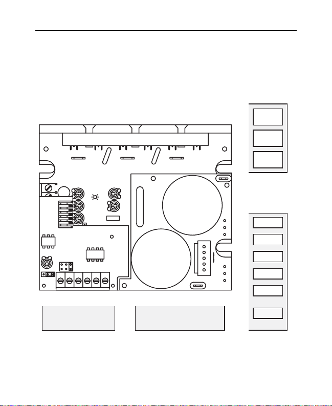
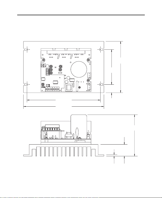
2
Figure 2. VFD01-230AC, VFD02-115AC, VFD02-230AC Dimensions
Dimensions
J502J503
L1
L2
ACAC -
H
4.30 [109]
2.12 [54]
0.96 [24]
3.80 [97]
VUW
TB501
BOOST
DECEL
FAULT
POWER
TQ LIMIT
TQ
ACCEL
IC502
MAX
C510
J501 JMP501
0.97 [25]
TOTAL HEIGHT (H)
(TOP OF CAP TO BOTTOM OF CHASSIS)
VFD01-230AC 2.03 [51.6]
VFD02-115AC 2.68 [68.1]
2.72 [69]
3.70 [94]
E2 E1 S3S2S1 D
VFD02-230AC 2.48 [ 63.0]
ALL DIMENSIONS IN
INCHES [MILLIMETERS]
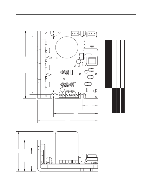
3Dimensions
Figure 3. VFD04-115AC and VFD04-230AC Dimensions
4.40 [112]
3.00 [72]
0.7 [18]
J502J503
L1
L2
ACAC -
1.00 [25]
YUW
TQ LIMIT
BOOST
TQ
ACCEL
DECEL
TB501
E2 E1S1 S2 S3 D
FAULT
POWER
IC502
MAX
C510
J501 JMP501
6.30 [160]
0.13 [3]
6.90 [175]
ALL DIMENSIONS IN INCHES [MILLIMETERS]
3.68 [93.5]
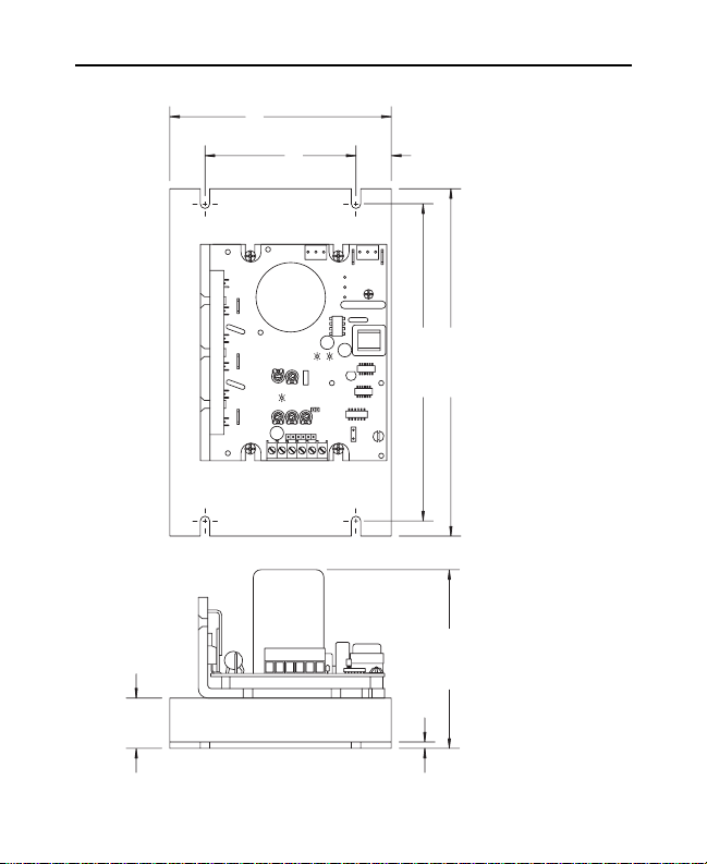
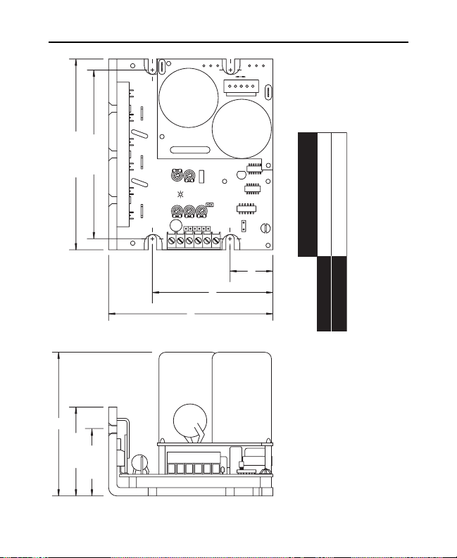
4 Dimensions
Figure 4. VFD01-230AC-PCM, VFD02-115AC-PCM
and VFD02-230AC-PCM Dimensions
TB501
2:0-10VDC
3:4-20MA
ZERO
4 mA
SET
JMP502
E2
321
JMP501:INPUT RANGE
1:0-5VDC
E1
DECEL
ACCEL
S1S2S3
4.30 [109]
3.80 [97]
VUW
BOOST
TQ
TQ LIMIT
FAULT
JMP502:INPUT TYPE
2-3:CURRENT
1-2:VOLTAGE
TB501
D
ACAC -
L2
L1
3.70 [94]
2.72 [69]
J502J503
0.97 [25]
E2 E1 S3S2S1 D
2.12 [54]
0.96 [24]
TOTAL HEIGHT (H)
(TOP OF CAP TO
VFD01-230AC -PCM 2.03 [51.6]
VFD02-115AC-PCM 2.68 [68.1]
VFD02-230AC-PCM 2.48 [63.0]
BOTTOM OF CHASSIS)
ALL DIMENSIONS IN
INCHES [MILLIMETERS]
H
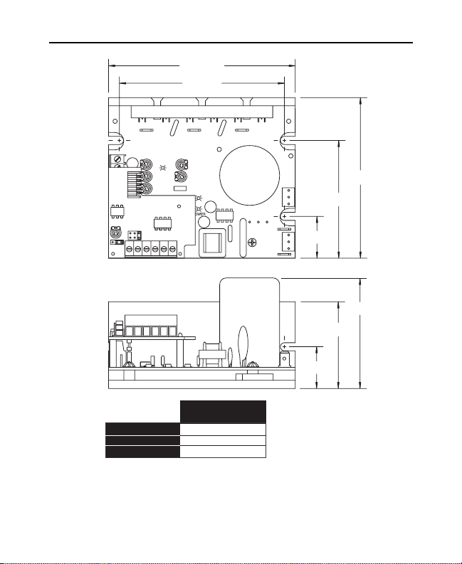
5Dimensions
Figure 5. VFD04-115AC-PCM and VFD04-230AC-PCM Dimensions
TB501
2:0-10VDC
ZERO
4 mA
3:4-20MA
SET
JMP502
321
YUW
BOOST
DECEL
TQ
ACCEL
TQ LIMIT
FAULT
JMP501:INPUT RANGE
JMP502:INPUT TYPE
2-3:CURRENT
1-2:VOLTAGE
1:0-5VDC
POWER
TB501
S1S2S3E2E1
D
ACAC -
L2
J502J503
L1
4.40 [112]
3.00 [72]
0.70 [18]
6.30 [160]
6.90 [175]
E2 E1 S1 S2 S3 D
ALL DIMENSIONS IN
INCHES [MILLIMETERS]
3.68 [93.5]
1.00 [25]
0.12 [3]
Dimensions6
Figure 6. VFD01-D230AC & VFD02-D230AC Dimensions
H
3.80 [97]
4.30 [109]
2.12 [54]
0.96 [24]
L2
C501
TH501
VUW
BOO
TQ
ACCEL
DECEL
TB501
115V230V
L1
J501
C502
TQ
IC502
MAX
C510
J501 JMP501
2.56 [65.0] MAX
TOTAL HEIGHT
(TOP OF CAP TO BOTTOM OF CHASSIS)
0.97 [25]
2.72 [69]
3.70 [94]
E2 E1 S3S2S1 D
VFD01-D230AC
3.02 [76.7] MAX
VFD02-D230AC
ALL DIMENSIONS IN
INCHES [MILLIMETERS]

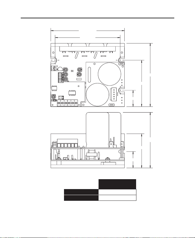
7Dimensions
Figure 7. VFD04-D230AC Dimensions
4.40 [112]
3.00 [72]
0.70 [18]
1.00 [25]
L2
TH501
YUW
BOO
DECEL
TB501
E2 E1 S1 S2 S3 D
115V230V
L1
J501
C501
C502
TQ
IC502
TQ
ACCEL
MAX
C510
J501 JMP501
6.30 [160]
0.13 [3]
6.90 [175]
ALL DIMENSIONS IN INCHES [MILLIMETERS]
4.45 [113] MAX
8 Dimensions
Figure 8. VFD01-D230AC-PCM and VFD02-D230AC-PCM Dimensions
TB501
ZERO
4 mA
SET
321
4.30 [109]
3.80 [97]
VUW
TH501
BOO
DECEL
TQ
ACCEL
JMP501:INPUT RANGE
2:0-10VDC
1:0-5VDC
3:4-20MA
JMP502
S1S2S3E2E1
D
TB501
2-3:CURRENT
C501
TQ
C502
JMP502:INPUT TYPE
1-2:VOLTAGE
L2
3.70 [94]
J501
115V230V
L1
2.72 [69]
0.97 [25]
E2 E1 S1 S2 S3 D
H
2.00 [51]
0.96 [24]
TOTAL HEIGHT
(TOP OF CAP TO
BOTTOM OF CHASSIS)
VFD01-D230AC-PCM 2.56 [65.0] MAX
VFD02-D230AC-PCM 3.02 [76.7] MAX
ALL DIMENSIONS IN INCHES [MILLIMETERS]
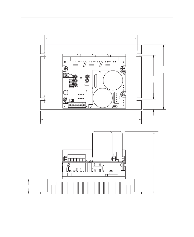
9Dimensions
Figure 9. VFD04-D230AC-PCM Dimensions
6.30 [160]
INCHES [MILLIMETERS]
1.00 [25]
YUW
TB501
JMP501:INPUT RANGE
1:0-5VDC
2:0-10VDC
3:4-20MA
ZERO
4 mA
SET
JMP502
S1S2S3E2E1
321
TH501
BOO
DECEL
TQ
ACCEL
C501
TQ
C502
JMP502:INPUT TYPE
2-3:CURRENT
1-2:VOLTAGE
TB501
D
L2
J501
115V230V
L1
6.90 [175]
ALL DIMENSIONS IN
E2 E1 S1 S2 S3 D
4.40 [112]
3.00 [76]
0.70 [18]
4.45 [113] MAX

10
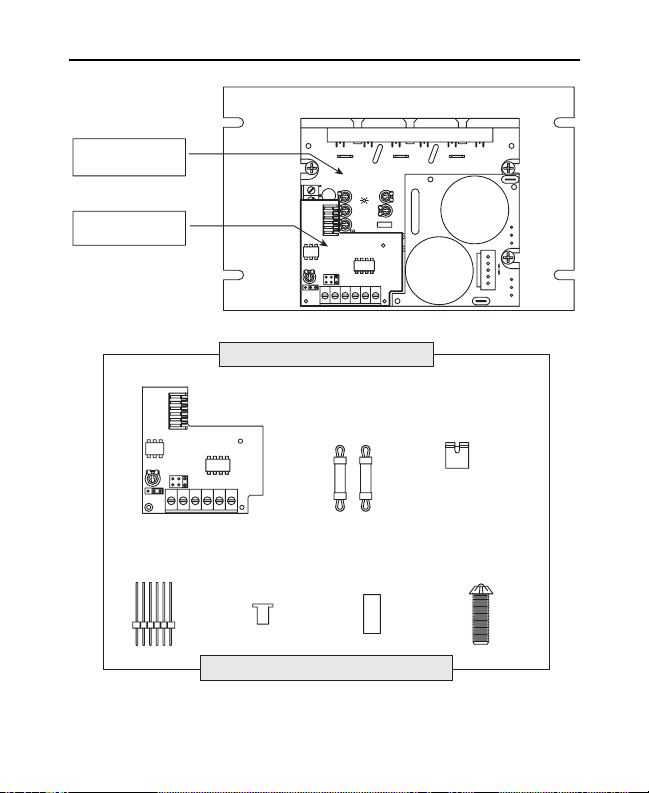
The VFD Series - PCM Adder Board accepts a 0 - 5 VDC,
0 - 10 VDC, or 4-20 mA signal and outputs an isolated 0-5
VDC signal without requiring additional panel space. It
mounts directly over the main AC board (bottom board) thus
maintaining the same footprint. Step-by-step information for
mounting the -PCM Adder Board to a VFD Series drive is
shown on pages 12 - 14.
Figure 10 (page 11) shows a VFD Series drive with the -PCM
adder board installed on the unit and the parts supplied in the
-PCM adder kit.
- PCM Isolation Option Board Mounting
Installation
11
Figure 10. VFD Series Drive with PCM adder board & -PCM adder kit
Installation
MAIN AC BOARD
(BOTTOM BOARD)
PCM ADDER
BOARD
TB501
1:0-5VDC
2:0-10VDC
3:4-20MA
ZERO
4 mA
SET
JMP502
321
YUW
TH501
BOO
DECEL
TQ
ACCEL
JMP501:INPUT RANGE
S1S2S3E2E1
C501
TQ
C502
JMP502:INPUT TYPE
2-3:CURRENT
1-2:VOLTAGE
TB501
D
L2
J501
115V230V
L1
PARTS SUPPLIED IN THIS KIT
J501
ZERO
4 mA
SET
JMP502
321
6-PIN
HEADER (1)
1:0-5VDC
2:0-10VDC
3:4-20MA
E2
E1
PCM ADDER
BOARD (1)
JMP501:INPUT RANGE
S1S2S3
JMP502:INPUT TYPE
2-3:CURRENT
1-2:VOLTAGE
TB501
D
SHOULDER
WASHER (1)
PCB
STANDOFF (2) JUMPER (1)
0.578" NYLON
SPACER (1)
6-32 x 1 5/16"
PHILLIPS SCREW (1)
Required Tools: Phillips Screwdriver
12 Installation
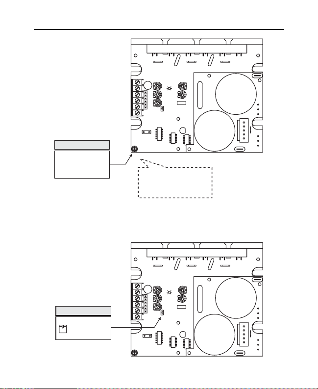
S T E P # 1
USING A PHILLIPS
SCREWDRIVER REMOVE
SCREW AND PLASTIC CAP
FROM BOTTOM BOARD
AND DISCARD.
S T E P # 2
PLACE THE JUMPER
(NOTCH SIDE UP)
ON JMP501 OF THE
BOTTOM BOARD.
TB501
DECEL
TQ
ACCEL
MAX
J501 JMP501
C510
FROM THE BOTTOM BOARD.
TB501
J501 JMP501
C510
IC502
NOTE:
DO NOT REMOVE THE
SHOULDER WASHER
DECEL
TQ
ACCEL
MAX
IC502
VUW
TH501
BOO
C501
TQ
C502
L2
J501
115V230V
L1
VUW
TH501
BOO
C501
TQ
C502
L2
J501
115V230V
L1

13Installation
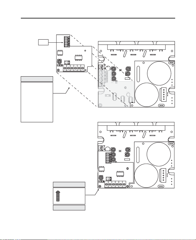
S T E P # 4
SNAP THE
SHORT
SIDE OF THE
6-PIN HEADER
INTO J501
LOCATED ON
THE BOTTOM
BOARD
S T E P # 3
INSTALL TWO
(2) PLASTIC
STANDOFFS
ONTO BOTTOM
BOARD
J501
VUW
TB501
MAX
J501 JMP501
C510
TB501
MAX
J501 JMP501
C510
TH501
DECEL
BOO
TQ
ACCEL
C501
TQ
C502
IC502
VUW
TH501
DECEL
BOO
TQ
ACCEL
C501
TQ
C502
IC502
L2
J501
115V230V
L1
L2
J501
115V230V
L1
S T E P # 5
INSERT THE SHOULDER
WASHER (included with
the kit) THROUGH THE
TOP SIDE OF THE PCM
ADDER BOARD.
J501
TOP VIEW TOP VIEW
JMP501:INPUT RANGE
JMP502:INPUT TYPE
1:0-5VDC
2:0-10VDC
3:4-20MA
2-3:CURRENT
ZERO
4 mA
SET
321
1-2:VOLTAGE
JMP502
TB501
S1S2S3E2E1
D
SIDE VIEW
J501
JMP501:INPUT RANGE
1:0-5VDC
2:0-10VDC
3:4-20MA
ZERO
4 mA
SET
JMP502
S1S2S3E2E1
321
SIDE VIEW
SPACER TO THE BOTTOM
SIDE OF THE SHOULDER
WASHER AS SHOWN.
JMP502:INPUT TYPE
2-3:CURRENT
1-2:VOLTAGE
TB501
D
S T E P # 6
ATTACH THE 0.578"
14 Installation
501
J501
S T E P # 7
POSITION THE PCM
ADDER BOARD OVER
THE BOTTOM BOARD
AS SHOWN.
NOTE: First align the
bottom holes of J501 (on
the PCM adder board) with
the 6 pin header installed
on the bottom board. The
PCM adder board will
snap into place at J501
and the two standoffs.
INSTALLATION COMPLETE.
J501
JMP501:INPUT RANGE
1:0-5VDC
2:0-10VDC
3:4-20MA
ZERO
4 mA
SET
JMP502
E2
E1
321
S T E P # 8
SECURE THE
PCM ADDER
BOARD WITH
THE 6-32 x 1 5/16"
PHILLIPS SCREW.
S1S2S3
JMP502:INPUT TYPE
2-3:CURRENT
1-2:VOLTAGE
TB501
TB501
D
MAX
MP
J501 JMP501
C510
510
VUW
DECEL
ACCEL
TH501
BOO
TQ
C501
TQ
C502
IC502
2
L2
J501
115V230V
L1
VUW
TB501
DECEL
J501
ACCEL
JMP501:INPUT RANGE
1:0-5VDC
2:0-10VDC
3:4-20MA
ZERO
4 mA
SET
JMP502
S1S2S3
E2
E1
321
TH501
BOO
TQ
D
TB501
2-3:CURRENT
1-2:VOLTAGE
C501
TQ
C502
JMP502:INPUT TYPE
L2
J501
115V230V
L1
 Loading...