

Minarik Drives VFDP4X04-D230-PCM Quick Start Guide
0.850
[22]
6
]
]
0.188
]
]
R
S
D
OFF
JUS
D
E
0
[
]
3.40
[
]
]
CONDU
S
S
]
]
]
0
1
2
5
6
7
8
9
1
0
Variable Frequency Drive for
3-phase & single phase AC motors
QUICK START GUIDE
VFDP4X04-D230-PCM
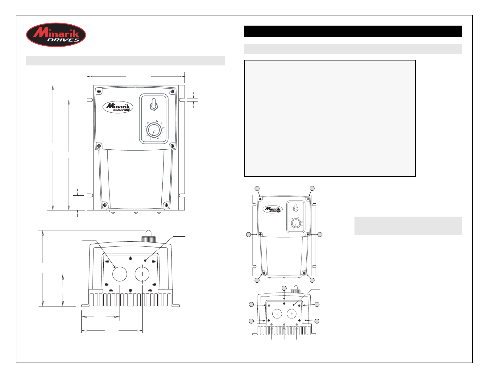
DIMENSIONS
SPECIFICATIONS
1-Phase Input . . . . . . . . . . . . . . . . . . . . . . . . . . . . . . . . . . . . . . . . . . . . . .* 115/230 VAC
1 or 3 -Phase Output . . . . . . . . . . . . . . . . . . . . . . . . . . . . . . . . . . . . . . . . . . . . .230 VAC
Maximum Horsepower . . . . . . . . . . . . . . . . . . . . . . . . . . . . . . . . . . . . . . . . . . . . . . .1 HP
Maximum Continuous Output Current . . . . . . . . . . . . . . . . . . . . . . . . . . . . . . . . 4.0 AC
AC Amps In . . . . . . . . . . . . . . . . . . . . . . . . . . . . . . . . . . . . . . . . . . . . . . . . .15 / 10 amps
AC Voltage Input Range . . . . . . . . . . . . . .115/230 VAC ± 10%, 50/60 Hz single phase
Standard Carrier Frequency . . . . . . . . . . . . . . . . . . . . . . . . . . . . . . . . . . . . . . . . .16 KHz
Adjustable Braking Current . . . . . . . . . . . . . . . . . . . . . . . . . . . . . . . . . . . . . . .0 - 4 ADC
Adjustable Braking Time . . . . . . . . . . . . . . . . . . . . . . . . . . . . . . . . . . . . . . . . .1 - 10 Sec.
Adjustable Minimum Speed . . . . . . . . . . . . . . . . . . . . . . . . . . . . . . . . . . . . . . . .0 - 30 Hz
Output Frequency Range . . . . . . . . . . . . . . . . . . . . . . . . . . . . . . . . . . . . . . . .0 - 120 Hz
Adjustable Maximum Output Frequency Range . . . . . . . . . . . . . . . . . . . . . .30 - 120 Hz
Acceleration Time Range . . . . . . . . . . . . . . . . . . . . . . . . . . . . . . . . . . . . . . . .1 - 12 secs
Deceleration Time Range . . . . . . . . . . . . . . . . . . . . . . . . . . . . . . . . . . . . . . . .1 - 12 secs
Analog Input Voltage Range (S1 [-] to S2 [+]) . . . . . 0 - 5 VDC, 0 - 10 VDC, 4 - 20 mA
Input Impedance, S1 to S2 . . . . . . . . . . . . . . . . . . . . . . . . . . . . . . . . . . . . .~ 100K ohms
Vibration . . . . . . . . . . . . . . . . . . . . . . . . . . . . . . . . . . . . . . . . . . . .0.5G max (20 - 50 Hz)
0.1G max (> 50 Hz)
Weight . . . . . . . . . . . . . . . . . . . . . . . . . . . . . . . . . . . . . . . . . . . . . . . . . . . . . . . . . .1.2 lbs
Ambient Operating Temperature Range . . . . . . . . . . . . . . . . . . . . . . . . . . . .10° - 40° C
* Jumper settings MUST
match input line voltage.
Application of 230 VAC
line input when jumpers
are set for 115 VAC will
result in severe damage
to the drive.
1. Remove the six (6) phillips screws on the
front case.
NOTE: The two shorter screws (#6 - 32 x 2
1/2) on the front case are used at hole
locations 5 & 6.
2. Remove the five (5) phillips screws on the
bottom plate.
NOTE: DO NOT REMOVE the three (3)
screws securing the bottom plate to the
heatsink.
R
S
D
OFF
E
E
G
K
6
3
0
1
2
5
6
7
8
9
1
0
REMOVING THE
CASE COVER
7.200 [183
.350 [161
0.73 [18.5
IT HOLE
2 PLACE
5.625 [143
POWE
PEE
AD
TABLE SPEE
REVERSING
AC MOTOR CONTROL
[5
BOTTOM PLAT
1
POWE
2
3
ADJUSTABLE SPEED
AC MOTOR CONTROL
PEE
REVERSING
4
4.56 [116
2.12 [53.8
2.2
55.9
5
1
2
4
BOTTOM PLAT
5
86.4
DO NOT REMOV
ALL DIMENSIONS IN INCHES [MILLIMETERS
THE THREE (3) SCREWS SECURIN
THE BOTTOM PLATE TO THE HEATSIN
STEP #4
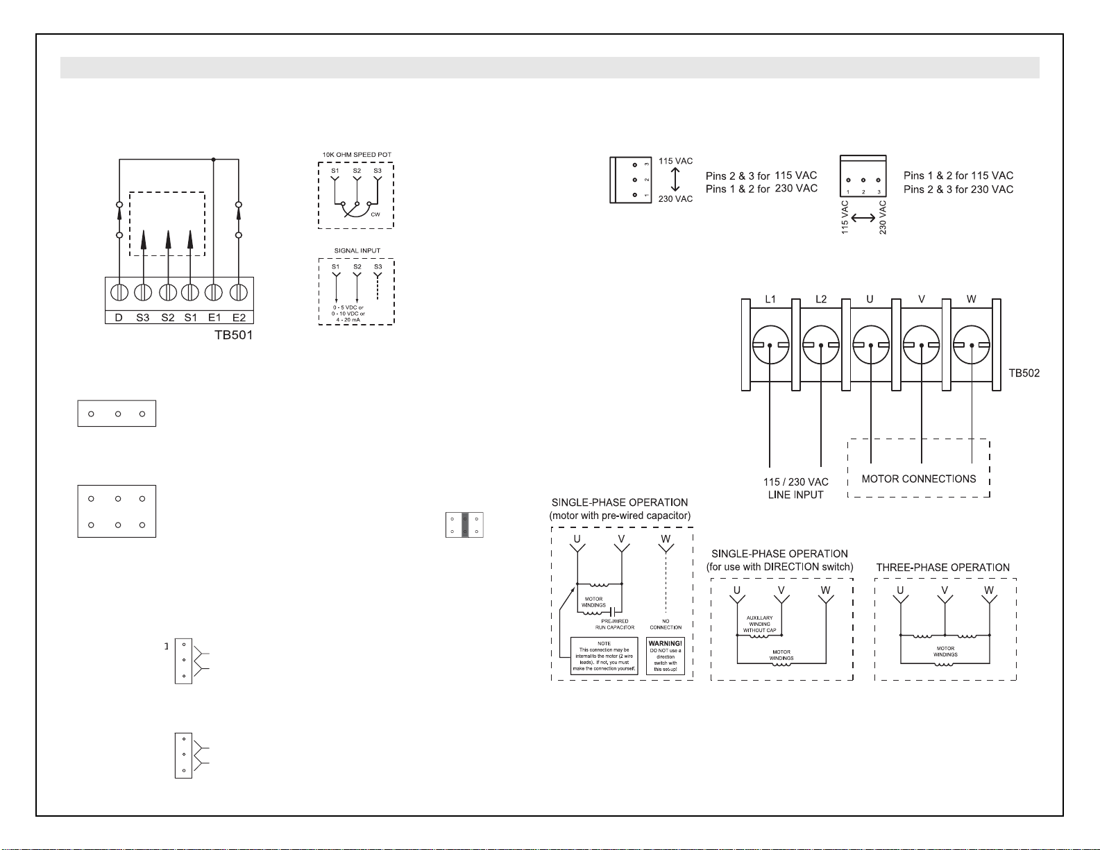
Configure jumpers JMP501 and JMP502 on the bottom board for 115 or 230 VAC Power Input.
STEP #2
Configure jumpers JMP504 and JMP505 on the top board for the appropriate signal input.
JMP50
3
3
JMP505
3
JMP505
:
STEP #3
Configure jumpers JMP503 on the bottom board and JMP506 on the top board.
JMP503
&
t
t
.
&
t
.
U
RES
T
506
ST
CONNECTIONS
STEP #5
Connect motor leads of a 3phase motor to U, V, and W
(TB502 on BOTTOM board)
using 14 - 16 AWG wire as
shown in the figure below.
STEP #6
Connect 115 or 230 VAC power
input using 12 AWG wire.
NOTE: Minarik strongly
recommends installing an
emergency stop switch on both
the L1 and L2 inputs.
STEP #1-skip this step if provided FWD/OFF/REV and speed potentiometer will be used.
Otherwise disconnect factory-wired connections from the FWD/OFF/REV switch and speed
potentiometer. Connect the enable/disable switch, direction switch, and speed potentiometer or
signal input to TB501 on the TOP board using 20 - 24 AWGwire as shown below.
Copyright 2003 by Minarik Corporation - All rights reserved. No part of this document may be reproduced or transmitted in any form without
written permission from Minarik Corporation. The information and technical data in this document are subject to change without notice.
Minarik Corporation and its Divisions make no warranty of any kind with respect to this material, including, but not limited to, the implied
warranties of its merchantability and fitness for a given purpose. Minarik Corproation and its Divisions assume no responsibility for any errors
that may appear in this document and make no commitment to update or to keep current the information in this document. mvd092503
MINARIK DRIVES
www.minarikdrives.com
14300 De La Tour Drive, South Beloit, IL 61080; Phone: (800) MINARIK (646-2745); Fax: (815) 624-6960
Document Number: 250-0379, Revision 2; Printed in the U.S.A. - December 2004
DIRECTION
SWITCH
TO SPEED POT
OR SIGNAL INPUT
ENABLE/DISABLE
SWITCH
(open to disable)
NOTE:
The factory-wired speed
potentiometer on the
case cover must be
disconnected prior to
wiring to a signal input
1 2
JMP504 (on top board)
Pins 1 & 2 for Voltage Input, or using a speed pot.
4
1 2
Pins 2 & 3 for Current Input
JMP505 (on top board)
Pins in Column 1 for 0 - 5 VDC Voltage Input,
or using a speed pot
Pins in Column 2 for 0 - 10 VDC Voltage Input
Pins in Column 3 for 4 - 20 mA Current Input
1 2
example
JMP501
JMP502
JMP503 (on bottom board)
Pins 1 & 2 to Trip
Pins 2
2
3
V TRIP
TAR
1
2
A
3 to Restar
TRIP: Drive has a low voltage fault & mus
be manually re-enabled to restart
RESTART: Drive has a low voltage fault
will momentarily stop then auto-restar
when input voltage returns to minimum level
JMP506 (on top board)
Pins 1 & 2 to Brake
Pins 2 & 3 to Coast
MP
 Loading...