

Minarik Drives RGD Series Users Manual
RGD Series
Models:
C1RGD03-D230AC
C1RGD10-D230AC
MMRGD03-D230AC
MMRGD03-D230AC-PCM
MMRGD10-D230AC
MMRGD10-D230AC-PCM
User ’s Manual
Digital SCR Regen,
Variable-Speed DC Drives

Copyright © 2002 by
Minarik Corporation
All rights reserved. No part of this manual may be reproduced or transmitted in any
form without written permission from Minarik Corporation. The information and
technical dat a in this manual are subject to change without notice. Minarik
Corporation and it s Divisions make no warranty of any kind with respect to this
material, including, but not limited to, the implied warranties of it s merchantability
and fitness for a given purpose. Minarik Corporation and it s Divisions assume no
responsibility for any errors that may appear in this manual and make no
commitment to update or to keep current the information in this manual.
Printed in the United States of America.

SHOCKAVOID
OID
ON
i
Safety Warnings
• This symbol denotes an important safety tip or warning.
Please read these instructions carefully before performing
any of the procedures contained in this manual.
• DO NOT INSTALL, REMOVE, OR REWIRE THIS EQUIPMENT
WITH POWER APPLIED. Have a qualified electrical technician
install, adjust and service this equipment. Follow the National
Electrical Code and all other applicable electrical and safety
codes, including the provisions of the Occupational Safety and
Health Act (OSHA), when installing equipment.
• Reduce the chance of an electrical fire, shock, or explosion by
proper grounding, over-current protection, thermal protection,
and enclosure. Follow sound maintenance procedures.
It is possible for a drive to run at full speed as a result
of a component failure. Minarik strongly recommends the
installation of a master switch in the main power input to
stop the drive in an emergency.
Circuit potentials are at 115 VAC or 230 VAC above earth
ground. Avoid direct contact with the printed circuit board or
with circuit elements to prevent the risk of serious injury or
fatality. Use a non-metallic screwdriver for adjusting the
calibration trimpots. Use approved personal protective
equipment and insulated tools if working on this drive with
power applied.
TI

ii
Table of Contents
Safety Warnings i
Regenerative Drives vii
Specifications 1
Dimensions 2
Installation 7
Drive mounting (General) . . . . . . . . . . . . . . . . . . . . . . . . . . . . . . . . . . . . . . . . . .7
Drive mounting (MMRGD) . . . . . . . . . . . . . . . . . . . . . . . . . . . . . . . . . . . . . . . . .7
Drive mounting (C1RGD) . . . . . . . . . . . . . . . . . . . . . . . . . . . . . . . . . . . . . . . . . .8
Wiring . . . . . . . . . . . . . . . . . . . . . . . . . . . . . . . . . . . . . . . . . . . . . . . . . . . . . . . . .10
Shielding guidelines . . . . . . . . . . . . . . . . . . . . . . . . . . . . . . . . . . . . . . . . . . . .11
Heat sinking . . . . . . . . . . . . . . . . . . . . . . . . . . . . . . . . . . . . . . . . . . . . . . . . . . .12
Line fusing . . . . . . . . . . . . . . . . . . . . . . . . . . . . . . . . . . . . . . . . . . . . . . . . . . . .12
Speed adjust potentiometer installation . . . . . . . . . . . . . . . . . . . . . . . . . . . . . . .14
Speed adjust potentiometer connections . . . . . . . . . . . . . . . . . . . . . . . . . . . .15
MMRGD . . . . . . . . . . . . . . . . . . . . . . . . . . . . . . . . . . . . . . . . . . . . . . . . . .15
CIRGD . . . . . . . . . . . . . . . . . . . . . . . . . . . . . . . . . . . . . . . . . . . . . . . . . . .15
Connections . . . . . . . . . . . . . . . . . . . . . . . . . . . . . . . . . . . . . . . . . . . . . . . . . . . .17
MMRGD . . . . . . . . . . . . . . . . . . . . . . . . . . . . . . . . . . . . . . . . . . . . . . . . . .17
Motor . . . . . . . . . . . . . . . . . . . . . . . . . . . . . . . . . . . . . . . . . . . . . . . . . .17
Power input . . . . . . . . . . . . . . . . . . . . . . . . . . . . . . . . . . . . . . . . . . . . .18
Line fuse . . . . . . . . . . . . . . . . . . . . . . . . . . . . . . . . . . . . . . . . . . . . . . .18
C1RGD . . . . . . . . . . . . . . . . . . . . . . . . . . . . . . . . . . . . . . . . . . . . . . . . . .21
Motor . . . . . . . . . . . . . . . . . . . . . . . . . . . . . . . . . . . . . . . . . . . . . . . . . .21
Power input . . . . . . . . . . . . . . . . . . . . . . . . . . . . . . . . . . . . . . . . . . . . .21
Selector switches . . . . . . . . . . . . . . . . . . . . . . . . . . . . . . . . . . . . . . . . . . . . . . .24
Voltage selector (SW501, SW502) . . . . . . . . . . . . . . . . . . . . . . . . . . . . . . .24
Feedback selector (SW503) . . . . . . . . . . . . . . . . . . . . . . . . . . . . . . . . . . . .24
Armature voltage selector (SW504) . . . . . . . . . . . . . . . . . . . . . . . . . . . . . . .24

Voltage follower . . . . . . . . . . . . . . . . . . . . . . . . . . . . . . . . . . . . . . . . . . . . . . . .27
MMRGD . . . . . . . . . . . . . . . . . . . . . . . . . . . . . . . . . . . . . . . . . . . . . . . . . .27
C1RGD . . . . . . . . . . . . . . . . . . . . . . . . . . . . . . . . . . . . . . . . . . . . . . . . . .27
Operation 28
Before applying power . . . . . . . . . . . . . . . . . . . . . . . . . . . . . . . . . . . . . . . . . . .28
MMRGD drive startup . . . . . . . . . . . . . . . . . . . . . . . . . . . . . . . . . . . . . . . . . . . .29
To start the drive . . . . . . . . . . . . . . . . . . . . . . . . . . . . . . . . . . . . . . . . . . .29
MMRGD drive shutdown . . . . . . . . . . . . . . . . . . . . . . . . . . . . . . . . . . . . . . . . . .29
C1RGD drive startup . . . . . . . . . . . . . . . . . . . . . . . . . . . . . . . . . . . . . . . . . . . .30
To start the drive . . . . . . . . . . . . . . . . . . . . . . . . . . . . . . . . . . . . . . . . . . .30
C1RGD drive shutdown . . . . . . . . . . . . . . . . . . . . . . . . . . . . . . . . . . . . . . . . . .30
Starting and Stopping Methods . . . . . . . . . . . . . . . . . . . . . . . . . . . . . . . . . . . . .31
Line starting and stopping . . . . . . . . . . . . . . . . . . . . . . . . . . . . . . . . . . . . . .31
Decelerate to a stop (MMRGD) . . . . . . . . . . . . . . . . . . . . . . . . . . . . . . . . . .32
Regenerative braking (MMRGD) . . . . . . . . . . . . . . . . . . . . . . . . . . . . . . . . .33
INHIBIT mode (MMRGD) . . . . . . . . . . . . . . . . . . . . . . . . . . . . . . . . . . . . . . .34
Disable/Enable terminals (MMRGD) . . . . . . . . . . . . . . . . . . . . . . . . . . . . . .35
Regenerative braking (C1RGD) . . . . . . . . . . . . . . . . . . . . . . . . . . . . . . . . . .36
Diagnostic LEDs . . . . . . . . . . . . . . . . . . . . . . . . . . . . . . . . . . . . . . . . . . . . . . . .37
Calibration 40
Minimum Speed (MIN SPD) . . . . . . . . . . . . . . . . . . . . . . . . . . . . . . . . . . . . . . . .42
Maximum Speed (MAX SPD) . . . . . . . . . . . . . . . . . . . . . . . . . . . . . . . . . . . . . .42
Forward Torque (FWD TQ) . . . . . . . . . . . . . . . . . . . . . . . . . . . . . . . . . . . . . . . .43
Reverse Torque (REV TQ) . . . . . . . . . . . . . . . . . . . . . . . . . . . . . . . . . . . . . . . . .44
IR Compensation (IR COMP) . . . . . . . . . . . . . . . . . . . . . . . . . . . . . . . . . . . . . .46
Forward Acceleration (FWD ACC) . . . . . . . . . . . . . . . . . . . . . . . . . . . . . . . . . .47
Reverse Acceleration (REV ACC) . . . . . . . . . . . . . . . . . . . . . . . . . . . . . . . . . .47
Tachogenerator (TACH) . . . . . . . . . . . . . . . . . . . . . . . . . . . . . . . . . . . . . . . . . .48
Signal Adjustment (SIGNAL ADJUST) . . . . . . . . . . . . . . . . . . . . . . . . . . . . . . .49
iiiContents
Application Notes . . . . . . . . . . . . . . . . . . . . . . . . . . . . . . . . . . . . . . . . . . . . . .51
Connection to DLC600 . . . . . . . . . . . . . . . . . . . . . . . . . . . . . . . . . . . . . . . . . . .51
Optional speed adjust potentiometer connections to MMRGD series drives . .52
Independent Adjustable Speeds (Forward Direction Only) . . . . . . . . . . . . . . . .53

Contents
iv
Table of Contents (cont.)
Independent Forward and Reverse Speeds . . . . . . . . . . . . . . . . . . . . . . . . . . .54
Independent Forward and Reverse Speeds With
FWD-STOP-REV Switch . . . . . . . . . . . . . . . . . . . . . . . . . . . . . . . . . . . . . . .55
Troubleshooting 56
Before troubleshooting . . . . . . . . . . . . . . . . . . . . . . . . . . . . . . . . . . . . . . . . . . .56
Replacement Parts . . . . . . . . . . . . . . . . . . . . . . . . . . . . . . . . . . . . . . . . . . . . . .59
Unconditional Warranty Inside Back Cover
Tables
Table 1. Recommended Line Fuse Sizes . . . . . . . . . . . . . . . . . . . . . . . . . . . . . .13
Table 2. Replacement Parts . . . . . . . . . . . . . . . . . . . . . . . . . . . . . . . . . . . . . . . . .59

Illustrations
Figure 1. Four-Quadrant Operation . . . . . . . . . . . . . . . . . . . . . . . . . . . . . . . . . . .viii
Figure 2. MMRGD Dimensions . . . . . . . .
Figure 3. MMRGD Dimensions with drive mounted on 223-0159 heat sink . . . . . .3
Figure 4. MMRGD-PCM Dimensions . . .
Figure 5. C1RGD Dimensions . . . . . . . . .
Figure 6. Heat Sink Dimensions . . . . . . . .
Figure 7. C1RGD Mounting Hole Locations . . . . . . . . . . . . . . . . . . . . . . . . . . . . . .9
Figure 8. MMRGD Speed Adjust Potentiometer . . . . . . . . . . . . . . . . . . . . . . . . . .14
Figure 9. MMRGD Speed Adjust Potentiometer Connections . . . . . . . . . . . . . . .16
Figure 10. MMRGD Power, Motor and Fuse Connections
(Bottom Board) . . . . . . . . . . . .
Figure 11. MMRGD-PCM Connections . .
Figure 12. C1RGD Power and Motor Conn
Figure 13. C1RGD Front Panel Switch Connections . . . . . . . . . . . . . . . . . . . . . .23
Figure 14. MMRGD Selector Switch Locations . . . . . . . . . . . . . . . . . . . . . . . . . . .25
Figure 15. C1RGD Selector Switch Locations . . . . . . . . . . . . . . . . . . . . . . . . . . .26
Figure 16. MMRGD Voltage Follower Connection . . . . . . . . . . . . . . . . . . . . . . . .27
Figure 17. RUN/STOP Switch . . . . . . . . .
Figure 18. MMRGD Regenerative Brake Terminals
With Optional RUN/BRAKE Switch . . . . . . . . . . . . . . . . . . . . . . . . . . .33
Figure 19. Inhibit Terminals Showing Optional Switch Installation . . . . . . . . . . . .34
Figure 20. Enable/Disable Terminals Showi
Optional Switch Installation . .
Figure 21. C1RGD Front Panel Switch Layout . . . . . . . . . . . . . . . . . . . . . . . . . . .36
Figure 22. MMRGD Diagnostic LED Location . . . . . . . . . . . . . . . . . . . . . . . . . . .38
Figure 23. C1RGD Diagnostic LED Location . . . . . . . . . . . . . . . . . . . . . . . . . . . .39
. . . . . . . . . . . . . . . . . . . . . . . . . . . . . . . .2
. . . . . . . . . . . . . . . . . . . . . . . . . . . . . . . .4
. . . . . . . . . . . . . . . . . . . . . . . . . . . . . . . .5
. . . . . . . . . . . . . . . . . . . . . . . . . . . . . . .6
. . . . . . . . . . . . . . . . . . . . . . . . . . . . . . .19
. . . . . . . . . . . . . . . . . . . . . . . . . . . . . . .20
ections . . . . . . . . . . . . . . . . . . . . . . . .22
. . . . . . . . . . . . . . . . . . . . . . . . . . . . . . .32
ng
. . . . . . . . . . . . . . . . . . . . . . . . . . . . . . .35
v

vi
Illustrations (cont.)
Figure 24. Calibration Trimpot Layout . . . . . . . . . . . . . . . . . . . . . . . . . . . . . . . . . .41
Figure 25. Recommended IR COMP, REVERSE TORQUE and FORWARD
TORQUE Settings . . . . . . . . . . . . . . . . . . . . . . . . . . . . . . . . . . . . . . . .50
Figure 26. MMRGD Connection to DLC600 . . . . . . . . . . . . . . . . . . . . . . . . . . . . .51
Figure 27. Forward-Reverse Switch . . . . . . . . . . . . . . . . . . . . . . . . . . . . . . . . . . .52
Figure 28. Forward-Stop-Reverse Switch . . . . . . . . . . . . . . . . . . . . . . . . . . . . . . .52
Figure 29. Independent Adjustable Speeds
(Forward Direction) . . . . . . . . . . . . . . . . . . . . . . . . . . . . . . . . . . . . . . .53
Figure 30. Independent Forward and Reverse Speeds . . . . . . . . . . . . . . . . . . . .54
Figure 31. Independent Forward and Reverse Speeds with a
Forward-Stop-Reverse Switch . . . . . . . . . . . . . . . . . . . . . . . . . . . . . . .55

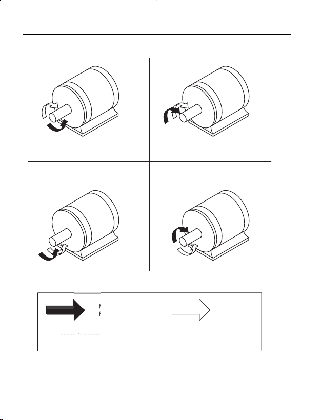
Regenerative Drives
Most non-regenerative variable-speed DC drives control current
flow to a motor in one direction. The direction of current flow is the
same direction as the motor rotation. Non-regenerative drives
operate in Quadrant 1 and Quadrant 3 if the drive is reversible (see
Figure 1, page viii). Motors must stop before reversing direction.
Unless dynamic braking is used, non-regenerative drives cannot
decelerate a load faster than coasting to a lower speed.
Regenerative drives operate in two additional quadrants: Quadrant
2 and Quadrant 4. In these quadrants, motor torque is in the
opposite direction of motor rotation.
Regenerative drives can reverse a motor without contactors,
switches, brake resistors and inhibit plugs. They can also control
an overhauling load and decelerate a load faster than it would t ake
to coast to a lower speed.
vii
viii
ON
OR
E
ON
OR
I
I
V
I
Regenerative Drives
uadrant I
uadrant II
T
TATI
ARROWS IN OPPOSITE DIRECTION = REGENERATIVE ACTI
uadrant
uadrant I
MOT
TORQU
Figure 1. Four-Quadrant Operation

Specifications
Maximum Armature
Armature Horsepower Horsepower Voltage
Model (DC Amps) (115 VAC Input) (230 VAC Input) (DC Volts)
C1RGD03-D230AC 3.0 1/20 – 1/4 1/10 – 1/2 0 – 180
C1RGD10-D230AC* 5.0 1/4 – 1/2 1/2 – 1 0 – 180
MMRGD03-D230AC 3.0 1/10 – 1/4 1/10 – 1/2 0 – 180
MMRGD03-D230AC-PCM 3.0 1/10 – 1/4 1/10 – 1/2 0 – 180
MMRGD10-D230AC** 5.0 1/4 – 1/2 1/2 – 1 0 – 180
MMRGD10-D230AC-PCM** 5.0 1/4 – 1/2 1/2 – 1 0 – 180
† With 230 VAC applied; 0 – 90 VDC with 115 VAC applied.
* When mounted to heat sink kit part number 223–0355, the maximum armature current
increases to 10 ADC and maximum horspower increases to 1 HP (115 VAC input) or 2
HP (230 VAC input).
** When mounted to heat sink kit part number 223–0159, the maximum armature current
increases to 10 ADC and maximum horsepower increases to 1 HP (115 VAC input) or 2
HP (230 VAC input).
AC Line Voltage 115/230 VAC ±10%, 50/60 Hz, single phase
Form Factor 1.37 at base speed
Acceleration Time Range 0.5 – 6 seconds
Deceleration Time Range 0.5 – 6 seconds
Analog Input Voltage Range (signal must be isolated; S0 to S2) -10 VDC to +10VDC
PCM Model Analog Input Voltage Range 0 - 10 VDC
Input Impedance (S0 to S2) 30 kΩ
PCM Model Input Impedance (POS to NEG) 1 kΩ
Load Regulation 1% base speed
Vibration 0.5G max. (20–50 Hz)
Ambient Temperature Range (chassis drives) 10°C–55°C
Ambient Temperature Range (enclosed drives)
Weight
Current Range Range Range †
10°C–40°C
1.1 lb
1
2
SO502
501
50
C
3
C
4
C50
C501
5
2
5
3
/CO
Q
]
]
]
]
]
]
2.8
3]
3
]
]
]
0
9
3
]
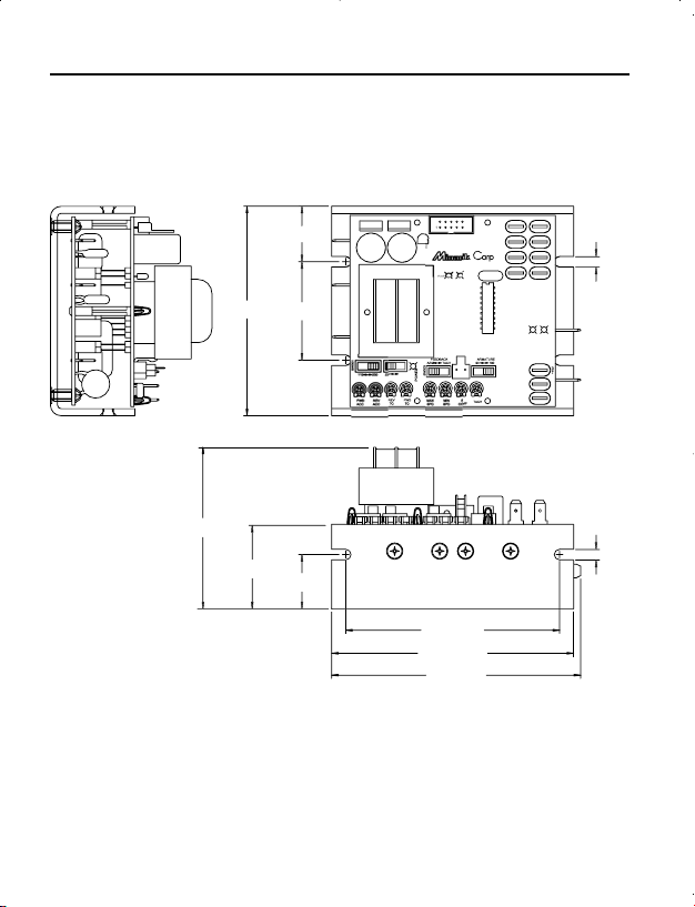
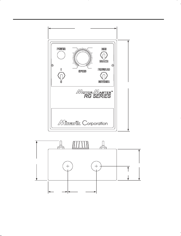
Dimensions
.72 [94
0.99 [25
1.75 [44
I
I
50
50
1
I
Y
I
T1 TACH T
11
7 [7
1.50 [38
0.96 [24
.80 [97
4.30 [109
4.42[112
ALL DIMENSIONS IN INCHES [MILLIMETERS]
Figure 2. MMRGD Dimensions
M
B1
1
2
4
W
0.188 [4.8
B
T
M
V
1
0.188 [4.8

Dimensions
/CO
5
5
E115
C501
50
C
4
C
3
SO502
]
8
]
]
]
]
98]
]
]
]
]
3
6.90 [175
6.30 [160
5.90 [150
I
I
50
50
M
B1
0.188 [4.
.70 [94
0.70 [18
I
1
W
ARMATUR
V
1
M
V
1
0.70 [18
4.40 [112
.87 [
1.00 [25
0.13 [3
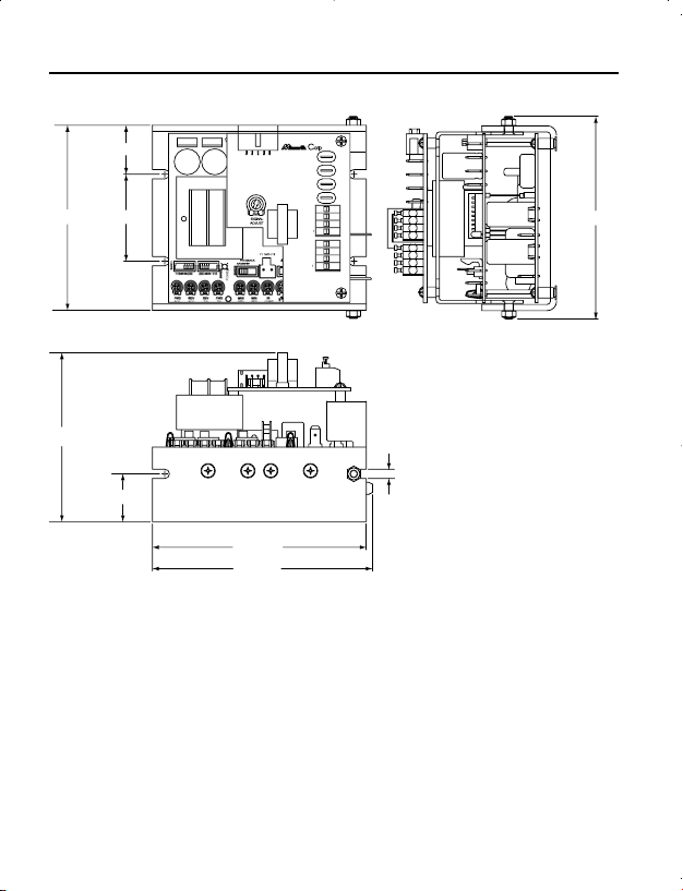
ALL DIMENSIONS IN INCHES [MILLIMETERS]
Figure 3. MMRGD Dimensions with drive mounted on 223-0159
heat sink
90
C
3
C
4
CH
1
3
COM
G
OS
/
/
3
3
COM
COM
3
502
503
501
501TB501
3
]
]
]
3
.72 [94
]
]
]
]
]
]
Dimensions4
0.99 [25
1.75 [44
I
I
50
50
TB
P
TA
RB
RB1
T
RB
B
RB1
NE
P
4.10 [104
.40 [86
0.188 [4.8
0.96 [24
4.30 [109
4.42 [112
ALL DIMENSIONS IN INCHES [MILLIMETERS]
Figure 4. MMRGD-PCM Dimensions
Dimensions
6.00 [152]
50
40
30
20
10
0
60
70
80
90
100
8.00 [203]
5
3.46 [88]
1.72
[44]
2.50
[64]
ALL DIMENSIONS IN INCHES [MILLIMETERS]
Figure 5. C1RGD Dimensions
2.75 [70]
1.25 [32]
6
]
]
]
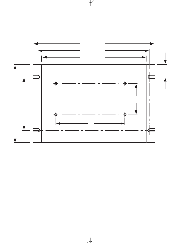
Dimensions
.90 [175
.30 [160
.90 [150
MOUNTING SLOTS 0.19 X 0.34 [5 X 9]
ALL DIMENSIONS IN INCHES [MILLIMETERS]
PART NO. DIM “A” DIM “B” DIM “C” DIM “D” DIM “E”
223-0159 4.40 [112] 3.00 [76] 0.7 [18] 1.75 [44] 3.90 [100]
223-0174 7.78 [198] 6.00 [152] 0.89 [23] 6.00 [152] 5.35 [136]
Heat sinks sold separately.
Figure 6. Heat Sink Dimensions

Installation
Drive mounting (General)
• Drive components are sensitive to electrostatic fields. Avoid
direct contact with the circuit board.
• Protect the drive from dirt, moisture, and accident al contact.
• Provide sufficient room for access to the terminal block and
calibration trimpots.
• Mount the drive away from heat sources. Operate the drive within
the specified ambient operating temperature range.
• Prevent loose connections by avoiding excessive vibration of
the drive.
Drive mounting (MMRGD)
• Mount the drive with its board in either a horizontal or vertical
plane. Eight (8) 0.188 inch [4.8 mm] wide slot s in the chassis
accept #8 pan head screws. Fasten either the large base or the
narrow flange of the chassis to the subplate.
7Installation
• The drive must be earth grounded for noise suppression.
Connect earth ground to the earth ground terminal on the drive’ s
bottom board (see Figure 10, page 19, for location).

8
Installation
Drive mounting (C1RGD)
C1RGD drives come with two (2) 0.88 inch [22 mm] conduit holes
at the bottom of the case. Units without a heatsink (5 ADC or
below) may be vertically wall mounted or horizont ally bench
mounted using the three keyholes on the back of the case. See
Figure 7 (page 9) for mounting hole locations of C1RGD controls
without a heatsink. For mounting of C1RGD controls with a
heatsink (over 5 ADC) the four (4) 0.188 inch [4.8 mm] wide slot s in
the heatsink. The slots accept #8 pan head screws. See Figure 6
(page 6) for mounting slot locations.
1. For access to the keyholes and the terminal strip, remove the
two screws from the front of the case by turning them
counterclockwise. Grasp the front cover and lift it straight out.
2. Install the mounting screws in the three keyholes.
3. Install conduit hardware through the conduit holes at the bottom
of the case. Connect external wiring to the terminal block.
4. Reinstall the front cover. Avoid pinching any wires between the
front cover and the case.
5. Replace the two screws to the front cover . Turn the screws
clockwise to tighten.
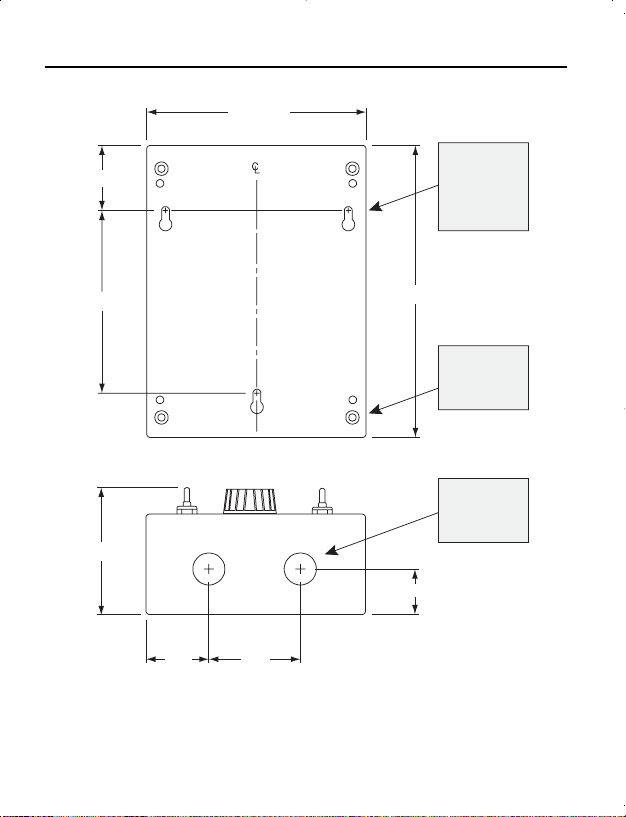
1.79 [45.0]
6.00 [152]
Installation
KEYHOLES
FOR #10
SCREW ON
BACKSIDE FOR
MOUNTING
(3 PLACES)
9
5.00 [127]
3.46 [88.0]
8.00 [203]
HEATSINK
MOUNTING
(4 PLACES)
TWO 0.88 [22.0]
HOLES ON
BOTTOM SIDE
1.25 [32]
6.00
[152]
2.50
[64.0]
ALL MEASUREMENTS IN INCHES [MILLIMETERS]
Figure 7. C1RGD Mounting Hole Locations
HOLES
CONDUIT

10
Installation
Wiring
Warning
Do not install, remove, or rewire this equipment with power
applied. Failure to heed this warning may result in fire,
explosion, or serious injury.
Circuit potentials are at 115 or 230 VAC above ground. To
prevent the risk of injury or fatality, avoid direct contact with
the printed circuit board or with circuit elements.
Do not disconnect any of the motor leads from the drive
unless power is removed or the drive is disabled. Opening
any one motor lead may destroy the drive.
• Use 18 AWG wire for speed adjust potentiometer wiring. Use 16
AWG wire for AC line (L1, L2) and motor (A1, A2) wiring.

Installation
Shielding guidelines
Warning
Under no circumstances should power and logic leads be
bundled together. Induced voltage can cause unpredictable
behavior in any electronic device, including motor controls.
As a general rule, Minarik recommends shielding of all conductors.
If it is not practical to shield power conductors, Minarik
recommends shielding all logic-level leads. If shielding of logic
leads is not practical, the user should twist all logic leads with
themselves to minimize induced noise.
It may be necessary to earth ground the shielded cable. If noise is
produced by devices other than the drive, ground the shield at the
drive end. If noise is generated by a device on the drive, ground
the shield at the end away from the drive. Do not ground both ends
of the shield.
If the drive continues to pick up noise af ter grounding the shield, it
may be necessary to add AC line filtering devices, or to mount the
drive in a less noisy environment.
11
Logic wires from other input devices, such as motion controllers
and PLL velocity controllers, must be separated from power lines in
the same manner as the logic I/O on this drive.

12
Installation
Heat sinking
MMRGD10 series drives require heat sink kit 223-0159 when the
continuous armature current is above 5 ADC. C1RGD10 series
drives require heat sink kit 223-0355 when the continuous armature
current is above 5 ADC. MMRGD03 and C1RGD03 series drives
do not require an additional heat sink. Refer to Figure 6 (p age 6)
for C1RGD heat sink mounting hole locations.
Use a thermally conductive heat sink compound (such as Dow
Corning® 340 Heat Sink compound) between the drive chassis and
the heat sink surface for optimum heat transfer.
Line fusing
Minarik drives require fuses for protection. Use fast acting fuses
rated for 250 VAC or higher and approximately 150% of the
maximum armature current. Install a fuse on L1 if the input is 1 15
VAC. Fuse both L1 and L2 when the line volt age is 230 VAC. The
C1RGD drive is pre-wired with two internal 5A fuses (for C1RGD03
drives), or two 15A fuses (for C1RGD10 drives).
Table 1 lists the recommended line fuse sizes.

Installation
Table 1. Recommended Line Fuse Sizes
90 VDC Motor 180 VDC Motor Max. DC Armature AC Line Fuse
Horsepower Horsepower Current (amps) Size (amps)
1/20 1/10 0.5 3
1/15 1/8 0.8 3
1/8 1/4 1.5 5
1/6 1/3 1.7 5
1/4 1/2 2.5 8
1/3 3/4 3.5 8
1/2 1 5.0 10
3/4 1 1/2 7.5 15
1 2 10 20
Minarik Corporation offers two fuse kits: part number 050–0069
(3–8A Fuse Kit) and 050–0073 (5–20A Fuse Kit). Both fuse kits
include a 63mA pico fuse (part number 050–0081), which protects
the transformer and logic.
13
 Loading...