

Minarik Drives NRG-4Q Series Users Manual
NRG-4Q Series
USER MANUAL
Four Quadrant, Regenerative PWM Drives
For DC Brush Motors
MODELS
NRG02-D240AC-4Q
NRG02-D240AC-4Q-PCM
NRG05-D240AC-4Q
NRG05-D240AC-4Q-PCM
NRG10-115AC-4Q
NRG10-115AC-4Q-PCM

Copyright © 2005 by
Minarik Corporation
All rights reserved. No part of this manual may be reproduced or transmitted in any
form without written permission from Minarik Corporation. The information and
technical data in this manual are subject to change without notice. Minarik
Corporation and its Divisions make no warranty of any kind with respect to this
material, including, but not limited to, the implied warranties of its merchantability
and fitness for a given purpose. Minarik Corporation and its Divisions assume no
responsibility for any errors that may appear in this manual and make no
commitment to update or to keep current the information in this manual.
Printed in the United States of America.

i
Safety Warnings
• This symbol l denotes an important safety message. Please read these
sections very carefully before performing any calibration, repair, or other
procedure contained in this manual.
• Have a qualified electrical maintenance technician install, adjust, and service
this equipment. Follow the National Electrical Code and all other applicable
electrical and safety codes, including the provisions of the Occupational Safety
and Health Act (OSHA), when installing equipment.
• Reduce the chance of an electrical fire, shock, or explosion by proper grounding,
over current protection, thermal protection, and enclosure. Follow sound
maintenance procedures.
It is possible for a drive to run at full speed as a result of a
component failure. Minarik strongly recommends the installation
of a master switch in the main power input to stop the drive in an
emergency.
Circuit potentials are at 120 VAC or 240 VAC above earth ground.
Avoid direct contact with the printed circuit board or with circuit
elements to prevent the risk of serious injury or fatality. Use a
non-metallic screwdriver for adjusting the calibration trimpots.
Use insulated tools if working on this drive with power applied.
L

Specifications . . . . . . . . . . . . . . . . . . . . . . . . . . . . . . . . . . . . . . . . . . . . . . . .1
Dimensions . . . . . . . . . . . . . . . . . . . . . . . . . . . . . . . . . . . . . . . . . . . . . . . . . .4
Installation . . . . . . . . . . . . . . . . . . . . . . . . . . . . . . . . . . . . . . . . . . . . . . . . . .5
Mounting . . . . . . . . . . . . . . . . . . . . . . . . . . . . . . . . . . . . . . . . . . . . . . .5
Wiring . . . . . . . . . . . . . . . . . . . . . . . . . . . . . . . . . . . . . . . . . . . . . . . . . .6
Shielding guidelines . . . . . . . . . . . . . . . . . . . . . . . . . . . . . . . . . . .7
Speed adjust potentiometer . . . . . . . . . . . . . . . . . . . . . . . . . . . . . . . . . .8
Heat sinking . . . . . . . . . . . . . . . . . . . . . . . . . . . . . . . . . . . . . . . . . . . . .9
Line fusing . . . . . . . . . . . . . . . . . . . . . . . . . . . . . . . . . . . . . . . . . . . . . .9
Cage-clamp terminals . . . . . . . . . . . . . . . . . . . . . . . . . . . . . . . . . . . . .10
Connections . . . . . . . . . . . . . . . . . . . . . . . . . . . . . . . . . . . . . . . . . . . . .11
Power input connections . . . . . . . . . . . . . . . . . . . . . . . . . . . . . .11
Motor connections . . . . . . . . . . . . . . . . . . . . . . . . . . . . . . . . . . .12
Regenerative dump resistor connections . . . . . . . . . . . . . . . . . . .12
Top board terminals . . . . . . . . . . . . . . . . . . . . . . . . . . . . . . . . . .14
Signal and optional switch connections . . . . . . . . . . . . . . . . . . . . . . . .16
Speed adjust potentiometer connections . . . . . . . . . . . . . . . . . . . . . . .18
Voltage follower . . . . . . . . . . . . . . . . . . . . . . . . . . . . . . . . . . . . .19
Slide switches . . . . . . . . . . . . . . . . . . . . . . . . . . . . . . . . . . . . . . . . . .20
ARMATURE VOLTAGE OUT (SW501) . . . . . . . . . . . . . . . . . . . . .20
FEEDBACK SELECT (SW502) . . . . . . . . . . . . . . . . . . . . . . . . . .20
Headers . . . . . . . . . . . . . . . . . . . . . . . . . . . . . . . . . . . . . . . . . . . . . . .20
INHIBIT PERSONALITY (JMP501) . . . . . . . . . . . . . . . . . . . . . . .20
CONTROL MODE (JMP502) . . . . . . . . . . . . . . . . . . . . . . . . . . . .21
INHIBIT MODE (JMP503) . . . . . . . . . . . . . . . . . . . . . . . . . . . . . .21
CURRENT LIMIT OUT (J502) . . . . . . . . . . . . . . . . . . . . . . . . . . .21
OUTPUT HEADER (J504) . . . . . . . . . . . . . . . . . . . . . . . . . . . . . .22
Operation . . . . . . . . . . . . . . . . . . . . . . . . . . . . . . . . . . . . . . . . . . . . . . . . . 23
Before applying power . . . . . . . . . . . . . . . . . . . . . . . . . . . . . . . . . . . .23
Startup and shutdown . . . . . . . . . . . . . . . . . . . . . . . . . . . . . . . . . . . . .24
ii
Contents

Reversing the drive: . . . . . . . . . . . . . . . . . . . . . . . . . . . . . . . . . .24
Starting and stopping methods . . . . . . . . . . . . . . . . . . . . . . . . . . . . . . .25
Line starting and line stopping . . . . . . . . . . . . . . . . . . . . . . . . . .26
Automatic restart upon power restoration . . . . . . . . . . . . . . . . . .26
Decelerating to minimum speed . . . . . . . . . . . . . . . . . . . . . . . . .26
Inhibit terminals . . . . . . . . . . . . . . . . . . . . . . . . . . . . . . . . . . . . .27
Regenerative dump . . . . . . . . . . . . . . . . . . . . . . . . . . . . . . . . . . .28
Torque (Current) Control . . . . . . . . . . . . . . . . . . . . . . . . . . . . . . .31
NRG-4Q-PCM . . . . . . . . . . . . . . . . . . . . . . . . . . . . . . . . . . . . . . .31
Calibration . . . . . . . . . . . . . . . . . . . . . . . . . . . . . . . . . . . . . . . . . . . . . . . . .32
Calibration procedure . . . . . . . . . . . . . . . . . . . . . . . . . . . . . . . . . . . . .34
MINIMUM SPEED (MIN SPD) . . . . . . . . . . . . . . . . . . . . . . . . . . .35
INHIBIT OFFSET . . . . . . . . . . . . . . . . . . . . . . . . . . . . . . . . . . .36
INPUT OFFSET . . . . . . . . . . . . . . . . . . . . . . . . . . . . . . . . . . . . .37
FORWARD MAXIMUM SPEED (FWD MAX) . . . . . . . . . . . . . . . . .38
REVERSE MAXIMUM SPEED (REV MAX) . . . . . . . . . . . . . . . . .38
REGULATION (IR COMP) . . . . . . . . . . . . . . . . . . . . . . . . . . . . .39
MOTOR TORQUE LIMIT and REGEN TORQUE LIMIT . . . . . . . . .40
FORWARD ACCELERATION (FWD ACCEL) . . . . . . . . . . . . . . . .42
REVERSE ACCELERATION (REV ACCEL) . . . . . . . . . . . . . . . . .43
TACHOMETER (TACH) . . . . . . . . . . . . . . . . . . . . . . . . . . . . . . .44
Application Notes . . . . . . . . . . . . . . . . . . . . . . . . . . . . . . . . . . . . . . . . . . . .47
Connection to other Minarik devices . . . . . . . . . . . . . . . . . . . . . . . . . . .47
Optional speed adjust potentiometer connections . . . . . . . . . . . . . . . . .49
FWD-MIN SPD-REV Switch . . . . . . . . . . . . . . . . . . . . . . . . . . . .49
Independent Adjustable Speeds . . . . . . . . . . . . . . . . . . . . . . . . .50
Independent forward and reverse speeds . . . . . . . . . . . . . . . . . .51
Independent forward and reverse speeds using a
FWD-MIN SPD-REV switch . . . . . . . . . . . . . . . . . . . . . . . . .52
Troubleshooting . . . . . . . . . . . . . . . . . . . . . . . . . . . . . . . . . . . . . . . . . . . . .53
Before applying power: . . . . . . . . . . . . . . . . . . . . . . . . . . . . . . . . . . . .53
iiiContents

Diagnostic LEDs . . . . . . . . . . . . . . . . . . . . . . . . . . . . . . . . . . . . . . . . .54
CURRENT LIMIT . . . . . . . . . . . . . . . . . . . . . . . . . . . . . . . . . . . .54
MOTOR . . . . . . . . . . . . . . . . . . . . . . . . . . . . . . . . . . . . . . . . . . .54
REGEN . . . . . . . . . . . . . . . . . . . . . . . . . . . . . . . . . . . . . . . . . . .54
OVER VOLTAGE COAST . . . . . . . . . . . . . . . . . . . . . . . . . . . . . .55
CE Compliance . . . . . . . . . . . . . . . . . . . . . . . . . . . . . . . . . . . . . . . . . . . . . .60
Certificate of Compliance . . . . . . . . . . . . . . . . . . . . . . . . . . . . . . . . . .60
Compliance Requirements . . . . . . . . . . . . . . . . . . . . . . . . . . . . . . . . . .61
OEM Responsibility . . . . . . . . . . . . . . . . . . . . . . . . . . . . . . . . . .61
Installation . . . . . . . . . . . . . . . . . . . . . . . . . . . . . . . . . . . . . . . . .61
Enclosure . . . . . . . . . . . . . . . . . . . . . . . . . . . . . . . . . . . . . . . . .62
Wiring . . . . . . . . . . . . . . . . . . . . . . . . . . . . . . . . . . . . . . . . . . . .62
Grounding . . . . . . . . . . . . . . . . . . . . . . . . . . . . . . . . . . . . . . . . .62
AC Line Filters . . . . . . . . . . . . . . . . . . . . . . . . . . . . . . . . . . . . . .63
Unconditional Warranty . . . . . . . . . . . . . . . . . . . . . . . . . . . . . . . . . . . . . . .66
iv Contents

v
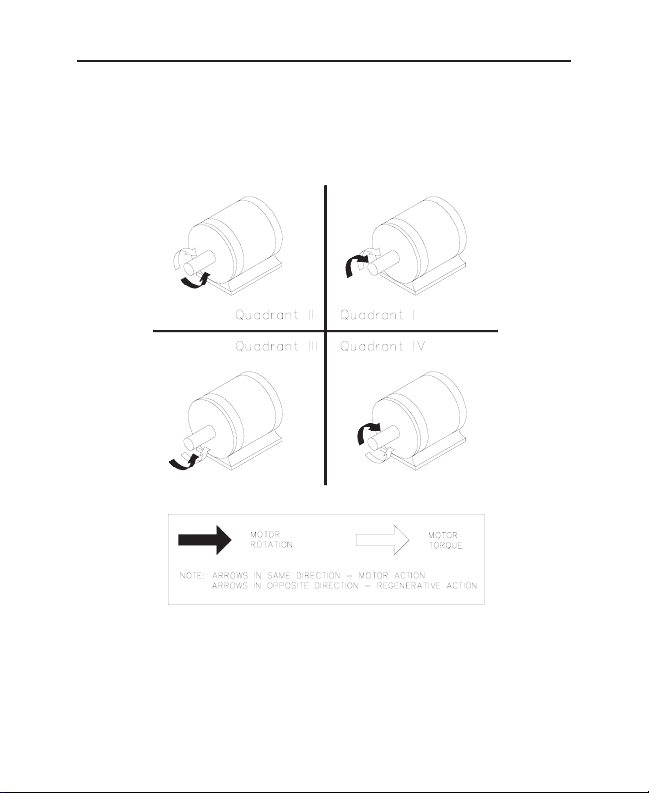
Figure 1. Four Quadrant Operation . . . . . . . . . . . . . . . . . . . . . . . . . . . . . . .x
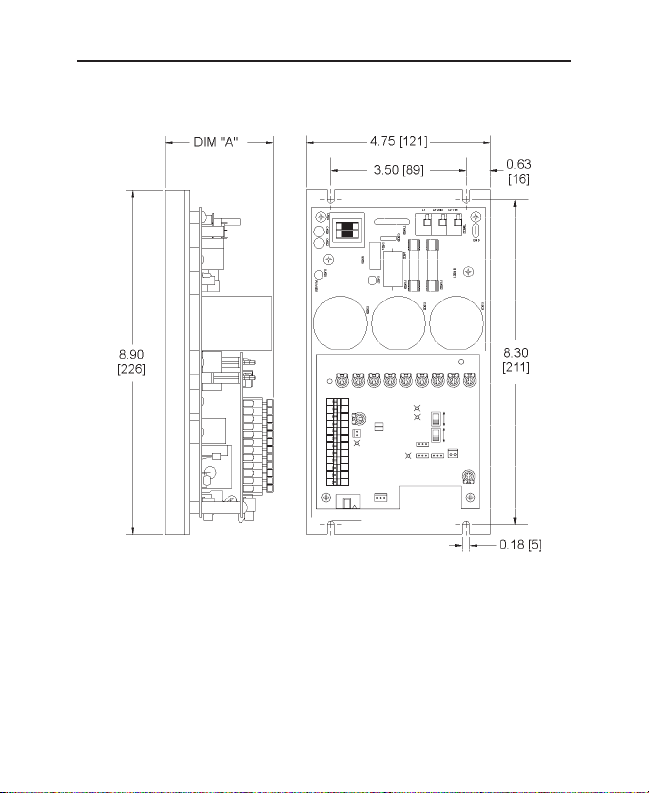
Figure 2. NRG–4Q Dimensions . . . . . . . . . . . . . . . . . . . . . . . . . . . . . . . . . .4
Figure 3. Speed Adjust Potentiometer . . . . . . . . . . . . . . . . . . . . . . . . . . . . .8
Figure 4. Cage-Clamp Terminal . . . . . . . . . . . . . . . . . . . . . . . . . . . . . . . . .10
Figure 5. Bottom Board Connections . . . . . . . . . . . . . . . . . . . . . . . . . . . . .13
Figure 6. Top Board Connections . . . . . . . . . . . . . . . . . . . . . . . . . . . . . . . .17
Figure 7. Speed Adjust Potentiometer Connections . . . . . . . . . . . . . . . . . .18
Figure 8. Voltage Follower Connections . . . . . . . . . . . . . . . . . . . . . . . . . . .19
Figure 9. Slide Switches, Headers and Terminals . . . . . . . . . . . . . . . . . . . .22
Figure 10. Regenerative Dump Circuit Connection . . . . . . . . . . . . . . . . . . . .30
Figure 11. Calibration Trimpot Layout . . . . . . . . . . . . . . . . . . . . . . . . . . . . .33
Figure 12. Typical Motor Torque, Regen Torque and IR Comp Settings
for NRG02/05-4Q Series Drives . . . . . . . . . . . . . . . . . . . . . . . . .45
Figure 13. Typical Motor Torque, Regen Torque and IR Comp Settings
for NRG10-4Q Series Drives . . . . . . . . . . . . . . . . . . . . . . . . . . .46
Figure 14. NRG–4Q Connection to DIGI-LOK Controls . . . . . . . . . . . . . . . . .47
Figure 15. NRG Connection to 200–0386A Limit Switch Logic Board . . . . . . .48
Figure 16. FWD / MIN SPD / REV Switch . . . . . . . . . . . . . . . . . . . . . . . . . . .49
Figure 17. Independent Adjustable Speeds (Forward Direction) . . . . . . . . . . .50
Figure 18. Independent Forward and Reverse Speeds . . . . . . . . . . . . . . . . .51
Figure 19. Independent Forward and Reverse Speeds Using a
FWD / MIN SPD / REV Switch . . . . . . . . . . . . . . . . . . . . . . . . . . .52
Figure 20. Diagnostic LED Location . . . . . . . . . . . . . . . . . . . . . . . . . . . . . . .56
Figure 21. CE Shielding, Ground and Filtering Connections . . . . . . . . . . . . .64
Illustrations

vi
Table 1. Recommended Line Fuse Sizes . . . . . . . . . . . . . . . . . . . . . . . . . .9
Table 2. Inhibit Plug Harness Assembly . . . . . . . . . . . . . . . . . . . . . . . . . .27
Table 3. Regenerative Dump Resistor Values . . . . . . . . . . . . . . . . . . . . . .28
Table 4. AC Line Filters . . . . . . . . . . . . . . . . . . . . . . . . . . . . . . . . . . . . . .63
Tables

vii
Minarik’s NRG–4Q Series drives are four-quadrant, regenerative PWM
drives. These open chassis drives come with the following features:
Pulse width modulation. Lower form factor than SCR drives (1.03 versus
1.37) throughout the motor speed range. Motor runs with greater efficiency
and less maintenance.
Four quadrant regenerative operation. see Regenerative drives section on
page ix.
Inhibit personality. Set the inhibit for your application needs: regenerative
brake for fast stopping, or coast for slower stopping. Normally open or
normally closed.
On board fusing. Protects the drive from high line current.
Cage-clamp terminals. Quicker and easier wiring than screw terminals.
Regenerative braking. No contactors required. No electromechanical
components to overheat or wear out.
Reverse on the fly. Switch from forward to reverse instantaneously.
Dual voltage input. Power the drive with either 120 VAC or 240 VAC.
Autoranging power supply.
Tachogenerator feedback option. Improve the speed regulation from
approximately 1% (armature feedback) to 0.1% with tachogenerator
feedback.
NRG–4Q Drives

viii NRG-4Q Drives
Diagnostic LEDs. Allows easy visual inspection of the drive status. Motor,
regen, current limit, and over voltage.
+15 and –15 VDC supply (50 mA maximum capacity each). Power external
devices with the drive’s power supply.
User adjustable trimpots. Calibrate the drive precisely to your application
needs.

ix
Most non-regenerative variable-speed DC drives control current flow to a
motor in one direction. The direction of current flow is the same direction as
the motor rotation. Non-regenerative drives operate in Quadrant 1, and also
in Quadrant 3 if the drive is reversible (see Figure 1 on page x).
Motors must stop before reversing direction. Unless dynamic braking is used,
non-regenerative drives cannot decelerate a load faster than coasting to a
lower speed.
Regenerative drives operate in two additional quadrants: Quadrant 2 and
Quadrant 4. In these quadrants, motor torque is in the opposite direction of
motor rotation. This allows regenerative drives to reverse a motor without
contactors or switches, to control an overhauling load, and to decelerate a
load faster than it would take to coast to a lower speed.
Regenerative Drives
x Regenerative Drives
Figure 1. Four Quadrant Operation

1
Model Number NRG02–D240AC–4Q (-PCM)
Type Open Chassis
AC Line Voltage 120 VAC or 240 VAC, ±10%, 50Hz or 60 Hz, single phase
Maximum Continuous Armature Current 2 ADC
Horsepower Range @ 130 VDC Output 1/20 – 1/4
Horsepower Range @ 240 VDC Output 1/10 – 1/2
Maximum Armature Voltage Range @ 120 VAC Input 0–130 VDC
Maximum Armature Voltage Range @ 240 VAC Input 0–240 VDC
Minimum Speed Adjustment Range @ 120 VAC Input 0–60 VDC
Minimum Speed Adjustment Range @ 240 VAC Input 0–120 VDC
Form Factor 1.05
Acceleration Time Range 0.1–20 seconds
Deceleration Time Range 0.1–20 seconds
Input Signal Range (signal must be isolated)** – 10 to +10 VDC
Input Impedance 47k Ohm
Speed Regulation (% of base speed) 1% open loop; 0.1% tach feedback
Tachogenerator Voltage Output Range 7 V/1000 RPM to 50V/1000 RPM
Vibration 0.5G max. (0–50 Hz); 0.1G max. (>50 Hz)
Weight 1.9 lb
Ambient Operating Temperature Range* 10°C–40°C
*External air flow is required to ensure temperature limits are not exceeded.
** (-PCM) drives do not require an isolated signal.
Specifications

2 Specifications
Model Number NRG05–D240AC–4Q (-PCM)
Type Open Chassis
AC Line Voltage 120 VAC or 240 VAC, ±10%, 50Hz or 60 Hz, single phase
Maximum Armature Current 5 ADC
Horsepower Range @ 130 VDC Output 1/8 – 3/4
Horsepower Range @ 240 VDC Output 1/4 – 1.5
Maximum Armature Voltage Range @ 120 VAC Input 0–130 VDC
Maximum Armature Voltage Range @ 240 VAC Input 0–240 VDC
Minimum Speed Adjustment Range @ 120 VAC Input 0–60 VDC
Minimum Speed Adjustment Range @ 240 VAC Input 0–120 VDC
Form Factor 1.05
Acceleration Time Range 0.1–20 seconds
Deceleration Time Range 0.1–20 seconds
Input Signal Range (signal must be isolated)** – 10 to +10 VDC
Input Impedance 47k Ohm
Speed Regulation (% of base speed) 1% open loop; 0.1% tach feedback
Tachogenerator Voltage Output Range 7V/1000 RPM to 50V/1000 RPM
Vibration 0.5G max. (0–50 Hz); 0.1G max. (>50 Hz)
Weight 1.9 lb
Ambient Operating Temperature Range* 10°C–40°C
*External air flow is required to ensure temperature limits are not exceeded.
** (-PCM) drives do not require an isolated signal.

Model Number NRG10–115AC–4Q (-PCM)
Type Open Chassis
AC Line Voltage 120 VAC, ±10%, 50Hz or 60 Hz, single phase
Maximum Armature Current 10 ADC
Horsepower Range @ 130 VDC Output 1/4 – 1.5
Maximum Armature Voltage Range @ 120 VAC Input 0–130 VDC
Minimum Speed Adjustment Range @ 120 VAC Input 0–60 VDC
Form Factor 1.05
Acceleration Time Range 0.1–20 seconds
Deceleration Time Range 0.1–20 seconds
Input Signal Range (signal must be isolated)** – 10 to +10 VDC
Input Impedance 47k Ohm
Speed Regulation (% of base speed) 1% open loop; 0.1% tach feedback
Tachogenerator Voltage Output Range 7V/1000 RPM to 50V/1000 RPM
Vibration 0.5G max. (0–50 Hz); 0.1G max. (>50 Hz)
Weight 1.9 lb
Ambient Operating Temperature Range* 10°C–40°C
*External air flow is required to ensure temperature limits are not exceeded.
** (-PCM) drives do not require an isolated signal.
3Specifications
4
Figure 2. NRG–4Q Dimensions
All dimensions in inches [millimeters]
NRG02–D240AC–4Q (-PCM) 2.79 [71]
NRG05–D240AC–4Q (-PCM) 3.13 [80]
NRG10–115AC–4Q (-PCM) 3.62 [92]
Dimensions
Model Height (Dim. “A”)
REGEN
MOTOR
FWD
REV
IR COMP
TACH
TORQUE
TORQUE
ACCEL
ACCEL
P509 P505 P503 P504 P507 P501 P506 P502 P510
1
+15 -15 S0 S3 S1 S2 RB2 RB1 COM DIR T1 T2
INHIBIT
OFFSET
IL504
CURRENT
LIMIT
12
+
- CURRENT
LIMIT
OUT
IL502
MOTOR
IL501
REGEN
JMP502
JMP501
C503
CONTROL MODE
INHIBIT
C502
1&2=VEL MODE
J502
PERSONALITY
2&3=CUR MODE
1&2=COAST
2&3=BRAKE
1 2 3
JMP503
INHIBIT MODE
JMP502
1&2=NO
2&3=NC
1 2 3
JMP501
IL503
OVER
VOLTAGE
COAST
J504
OUTPUTS
1=Iout
2=COM
3=Yout
1 2 3
J504J501
MIN
REV
FWD
SPD
MAX
MAX
SW501
130 VDC
ARMATURE
VOLTAGE OUT
240 VDC
ARMATURE
FEEDBACK
TACH/CUR MODE
SW502
1 2 3
JMP503
INHIBIT
P511
INPUT
OFFSET

5
Warning
Do not install, rewire, or remove this control with input power
applied. Doing so may cause fire or serious injury. Make sure you
have read and understood the Safety Warnings on page i before
attempting installation.
The chassis must be earth grounded. Use a star washer beneath the
head of at least one of the mounting screws to penetrate the
anodized chassis surface and to reach bare metal.
L
• Drive components are sensitive to electrostatic fields. Avoid direct contact
with the circuit board. Hold drive by the chassis only.
• Protect the drive from dirt, moisture, and accidental contact.
• Provide sufficient room for access to the terminal block and calibration
trimpots.
• Mount the drive away from heat sources. Operate the drive within the
specified ambient operating temperature range.
• Prevent loose connections by avoiding excessive vibration of the drive.
Installation
Mounting

6 Installation
• Mount the drive with its board in either a horizontal or vertical plane.
Preffered mounting is with fins vertical. Four 0.19 in. (5 mm) wide slots in
the chassis accept #8 pan head screws.
Wiring
• Use 18-24 AWG wire for speed adjust potentiometer wiring. Use 14–16
AWG wire for AC line (L1, L2) and motor (A1 and A2) wiring.
Warning
Do not install, remove, or rewire this equipment with power applied.
Doing so may cause fire or serious injury.
Circuit potentials are at 120 or 240 VAC above ground. To prevent
the risk of injury or fatality, avoid direct contact with the printed
circuit board or with circuit elements.
Do not disconnect any of the motor leads from the drive unless
power is removed or the drive is disabled. Opening any one motor
lead may destroy the drive. Do not fuse the motor line.
L
V

7Installation
As a general rule, Minarik recommends shielding of all conductors.
If it is not practical to shield power conductors, Minarik recommends
shielding all logic-level leads. If shielding logic leads is not practical, the
user should twist all logic leads with themselves to minimize induced noise.
It may be necessary to earth ground the shielded cable. If noise is produced
by devices other than the drive, ground the shield at the drive end. If noise is
generated by a device on the drive, ground the shield at the end away from
the drive. Do not ground both ends of the shield.
If the drive continues to pick up noise after grounding the shield, it may be
necessary to add AC line filtering devices, or to mount the drive in a less
noisy environment.
Logic wires from other input devices, such as motion controllers and PLL
velocity controllers, must be separated from power lines in the same manner
as the logic I/O on this drive.
Warning
Under no circumstances should power and logic leads be bundled
together. Induced voltage can cause unpredictable behavior in any
electronic device, including motor controls.
L
Shielding guidelines
8 Installation
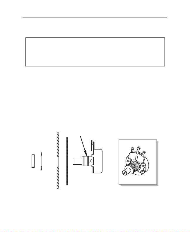
Install the circular insulating disk between the mounting panel and the 10K
ohm speed adjust potentiometer (see Figure 3). Mount the speed adjust
potentiometer through a 0.38 inch (10 mm) hole with the hardware provided.
Twist the speed adjust potentiometer wire to avoid picking up unwanted
electrical noise. If potentiometer leads are longer than 18 inches (46 cm),
use shielded cable.
Figure 3. Speed Adjust Potentiometer
Warning
Be sure that the potentiometer tabs do not make contact with the
potentiometer enclosure. Grounding the input will cause damage
to the drive.
L
Speed adjust potentiometer
MOUNT THROUGH A 0.38 IN. (10 MM) HOLE
WIPER
CW
NUT
STAR
WASHER
INSULATING DISK
PAN EL
SPEED ADJUST
POTENTIOMETER
POT TAB ASSIGNMENTS
CCW

9Installation
Heat sinking
All NRG-4Q Series drives have sufficient heat sinking in their basic
configurations. No additional heat sinking is required.
Line fusing
NRG Series drives have preinstalled line fuses. When replacing the line
fuses, use fast acting fuses rated for 250 VAC or higher, and at least 200%
of the armature current. See Table 1 for recommended line fuse sizes.
Table 1. Recommended Line Fuse Sizes
90 VDC Motor 180 VDC Motor Max. DC Armature AC Line Fuse
Horsepower Horsepower Current (amps) Size (amps)
1/20 1/10 0.5 3
1/15 1/8 0.8 3
1/8 1/4 1.5 5
1/6 1/3 1.7 5
1/4 1/2 2.6 8
1/3 3/4 3.5 8
1/2 1 5.0 10
3/4 - 7.6 15
1 - 10 20
10 Installation
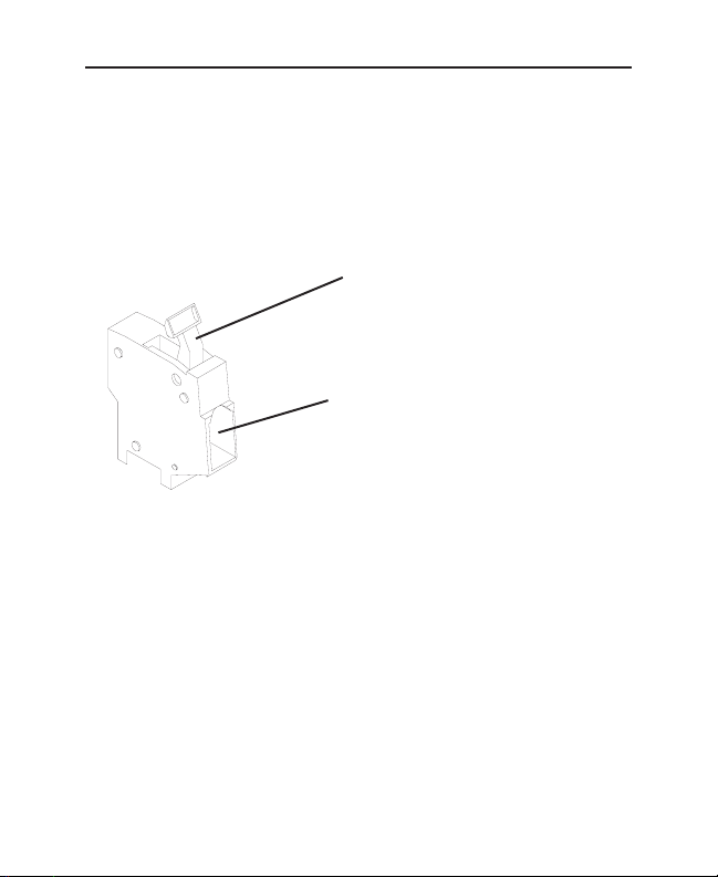
Cage-clamp terminals
All connections are made to cage-clamp terminals. To insert a wire into the
cage-clamp terminal:
1. Press down on the lever arm using a
small screwdriver. Unnecessary force
may cause damage.
2. Insert wire into the wire clamp.
3. Release the lever arm to clamp wire.
Figure 4. Cage-Clamp Terminal

11Installation
Connect the power input leads and a DC motor to TB501 and TB502 on the
drive’s printed circuit board (PCB) as shown in Figure 5 on page 13.
Power input connections
Connect the AC line voltage leads to terminals L1 and L2 on terminal board
TB502, or to a double-throw, single-pole master power switch
(recommended). If the line voltage is 120 VAC, connect the AC line voltage
leads to terminals L1 and
L2 (115). If the line voltage is 240 VAC, connect the AC line voltage leads to
terminals L1 and L2 (230).
Warning
Do not connect this equipment with power applied. Doing so may
cause fire or serious injury.
Minarik strongly recommends the installation of a master power
switch in the voltage input line, as shown in Figure 5 (page 13).
The switch contacts should be rated at a minimum of 200% of
motor nameplate current and 250 volts.
Do not connect 240 VAC line voltage to terminal L2 (115).
Fire or serious damage to the drive may result.
L
Connections

12 Installation
Motor connections
Minarik drives supply motor voltage from A1 and A2 terminals. It is assumed
throughout this manual that, when A1 is positive with respect to A2 , the
motor will rotate clockwise (CW) while looking at the output shaft protruding
from the front of the motor. If this is opposite of the desired rotation, simply
reverse the wiring of A1 and A2 with each other.
Connect a DC motor to TB501 terminals A1 and A2 as shown in Figure 5
(page 13). Ensure that the motor voltage rating is consistent with the drive’s
output voltage.
Regenerative dump resistor connections
If you plan to use braking to stop the motor or if reversing on the fly is
required, you must connect a regenerative dump resistor to TB501 terminals
DB+ and DB- as shown in Figure 5 (page 13).
The regenerative dump resistor reduces the voltage across the bus
capacitors (C503 and C504) when they reach their maximum voltage rating.
This occurs when the motor regenerates voltage back to the drive. Bus
capacitor maximum voltage ratings are 400 VDC for 240 VAC drives, and 200
VDC for 120 VAC drives. For more information on regenerative braking,
refer to the Regenerative braking section on page 28.
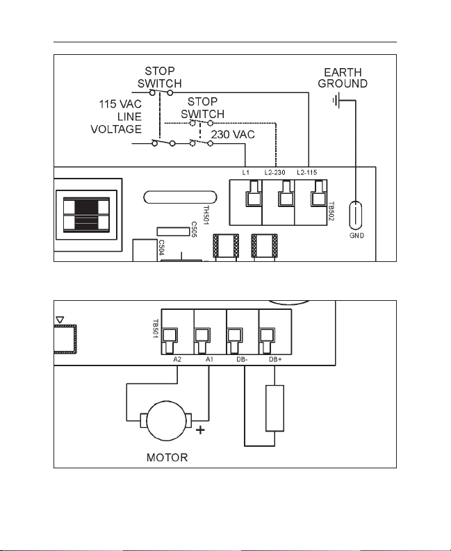
13Installation
Figure 5. Bottom Board Connections
Power and Ground Connections
Motor and Regenerative Dump Resistor Connections
Regenerative
Dump
Resistor
 Loading...