

Minarik Drives NRG-4Q SERIES Catalog Page
Drives for DC Brushed Motors
4Q PWM
D
UL
Field
Listed
(VDC)
– YES – –
– YES – –
Drive
NRG02-D240AC-4Q
NRG02-D240AC-4Q-PCM
NRG05-D240AC-4Q
NRG05-D240AC-4Q-PCM
Input
Voltage
(VAC)
115
230
115
230
115
230
115
230
Output
Voltage
Range
(VDC)
0-130
0-240
0-130
0-240
0-130
0-240
0-130
0-240
Max.
Armature
Current
HP Rating @
90/130 VDC
Output
HP Rating @
180/240 VDC
Output
Enclosure
Reversing
*****
Isolation
Supply
2 1/20 - 1/6 1/10 - 1/3 CHASSIS YES – – YES – –
2 1/20 - 1/6 1/10 - 1/3 CHASSIS YES
0 to ±10 VDC
4-20 mA
5 1/8 - 1/2 1/4 - 1 CHASSIS YES – – YES – –
5 1/8 - 1/2 1/4 - 1 CHASSIS YES
0 to ±10 VDC
4-20 mA
NRG10-115AC-4Q 115 0-130 10 1/4 - 1 – CHASSIS YES – – YES – –
NRG10-115AC-4Q-PCM 115 0-130 10 1/4 - 1 – CHASSIS YES
***** Applications that require braking and/or reversing of high inertia loads require a Regenerative Dumping resistor. Refer to the user’s manual for resistor sizing.
***** See the Accessories section for resistor part numbers (Pg 48).
0 to ±10 VDC
4-20 mA
– YES – –
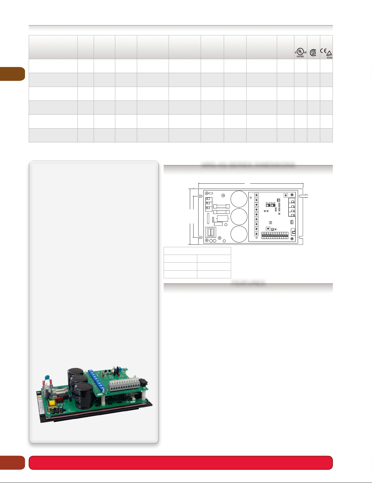
NRG-4Q SERIES DIMENSIONS
The NRG-4Q Series, with a robust set of features,
is easy to use and at the same time, will satisfy
demanding application requirements. This family of
drives is the highest performance drive line in the
Minarik Drives arsenal. Our OEM customers often
refer to the drive as a DC Servo. In addition to onboard fusing to protect your motor and drive, the
NRG will accept any AC input voltage between 90
and 240 VAC at 50 or 60Hz. With the auto-ranging
power supply there are no switches to set, no settings to change.
These highly efficient, near unity form factor PWM
regenerative drives will increase motor performance while reducing your energy costs. MOSFET
power in PWM drives switch at 16kHz (double edge
modulation), to provide fast circuit response and
the constant 1.05 (pure DC is 1.00) form factor
throughout the entire 100:1 speed range.
The NRG-4Q will work with logic signals, motion
controllers, and programmable logic controllers.
It is also compatible with Minarik Drives’ popular
200-0386A limit switch logic board (page 43
).
See page 52 for an in-depth comparison of the different 4Q drives.
NRG02-D240AC-4Q
NRG05-D240AC-4Q
NRG10-115AC-4Q
NRG02-D240AC-4Q-PCM
NRG05-D240AC-4Q-PCM
NRG10-115AC-4Q-PCM
NRG02 2.79 [71]
NRG05 3.13 [80]
NRG10 3.62 [92]
• 4Qreversing: Regenerative / 4 quadrant drives have the ability to per form
quick and contactorless reversing on-the-fly. Change the 4Q to a 2Q for a
lower cost regenerative stopping (no reversing) model.
Speedrange,regulation,&formfactor: 1% of base speed regulation with
•
a 100:1 speed range. 0.1% of base speed regulation with a 100:1 speed
range with the tachogenerator feedback. 1.05 form factor over the entire
range.
User adjustable calibration pots: Minimum Speed, Forward Maximum
•
Speed, Reverse Maximum Speed, Motor Torque, Regen Torque, IR Compensation, Forward Acceleration, Reverse Acceleration, Tachogenerator Feedback, Inhibit Offset and Input Offset.
DiagnosticLEDs: LEDs for motoring, regen (torque or braking), current limit
•
and overvoltage coast.
Stoppingmodes: User can decelerate (N.O.), regeneratively brake
•
(N.O. or N.C.) or coast the motor to a stop (N.O. or N.C.).
• Outputs: Signals propor tional to motor voltage, motor current, and to signal
the drive is in current limit.
Inhibitpersonalityswitch: Choose whether you brake or coast to a stop.
•
Use inhibit plug (201-0024).
Auto-rangingpowersupply: Can accept a 90-240 VAC or 80-340 VDC as
•
an alternative to an AC input. Connection will vary.
• RoHS: All NRG-4Q series models are RoHS compliant.
0.63 [ 16 ]
3.50 [ 89 ]
4.75 [ 121 ]
HEIGHT
8.30 [ 211 ]
GND
L2-115
L2 -230
L1
REV
MAX
FWD
MAX
MIN
SPD
IL502
FWD
ACCEL
MOTOR
REV
ACCEL
MOTOR
TORQUE
REGEN
TORQUE
INHIBIT
OFFSET
IR COMP
P509 P505 P503 P504 P507 P501 P506 P502 P510
TACH
1
+15 -15 S0 S3 S1 S2 RB2 RB1 COM DIR T1 T2
P511
INPUT
ARMATURE
CONTROL MODE
INHIBIT
C502
1&2=VEL MODE
PERSONALITY
J502
+
2&3=CUR MODE
1&2=COAST
FEEDBACK
2&3=BRAKE
- CURRENT
OFFSET
INHIBIT
TACH/CUR MODE
JMP503
1 2 3
SW502
JMP502
JMP501
1 2 3
1 2 3
IL503
OVER
COAST
VOLTAGE
JMP503
INHIBIT MODE
1&2=NO
2&3=NC
J504
OUTPUTS
1=Iout
LIMIT
OUT
IL504
CURRENT
LIMIT
0.18 [ 5 ]
A2 A1 DB-DB+
1 2 3
2=COM
3=Yout
J504J501
12
ARMATURE
VOLTAGE OUT
130 VDC
240 VDC
SW501
IL501
JMP502
REGEN
JMP501
C503
All dimensions in inches [millimeters]
Wiring diagrams can be found on page 67.
FEATURES
CSA
CE
TUV
20
•NRG-4QSERIES
 Loading...