


Instructions for Use
Models MM31700B/MM31701B/
MM31750B/MM31751B
Specifications
Line Voltage 115 VAC (-5%, +10%), 60 Hz
Horsepower Range
MM31700B/MM31750B 1/8 – 1/4 HP
MM31701B/MM31751B 1/50 – 1/10 HP
Armature Voltage Range 0 – 90 VDC
Ambient Temperature Range 10°C – 55°C
Models MM31700B and MM31701B are supplied with a
6-wire harness assembly and a 10K ohm single turn speed
adjust potentiometer as separate components packed with the
drive. Models MM31750B and MM31751B have the speed
adjust potentiometer mounted on the board support bracket and
include a 4-wire harness packed with the drive.
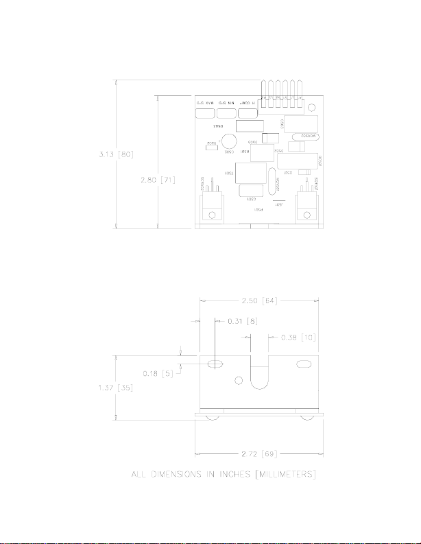
Figure 1. MM31700B/MM31701B Dimensions
Dimensions
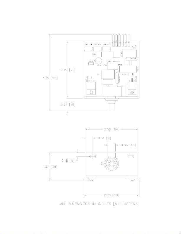
Figure 2. MM31750B/MM31751B Dimensions

Safety Warnings
• Have a qualified electrical maintenance technician install,
adjust, and service this equipment. Follow the National
Electrical Code (NEC) and all other applicable electrical and
safety codes, including the provisions of the Occupational
Safety and Health Act (OSHA) when installing equipment.
• Reduce the chance of an electrical fire, shock, or explosion
by proper grounding, over current protection, thermal
protection, and enclosure. Follow sound maintenance
procedures.
• It is possible for a drive to run at full speed as a result of a
component failure. Install a master switch in the AC line for
stopping the drive in an emergency.
• This drive is not isolated from earth ground. Circuit
potentials are at 115 VAC above earth ground. Avoid direct
contact with the printed circuit board or with circuit elements
to prevent the risk of serious injury or fatality. Use a nonmetallic screwdriver for adjusting the calibration trimpots.
Fusing
Minarik recommends fusing the drive. Use a fast acting fuse
rated for 250 volts, and approximately 150%–200% of the
maximum armature current. Fuse only the “hot” side of the AC
line (L1).

Figure 3. MM31700B/MM31701B Connections
6-WIRE HARNESS
INCLUDED
(MINARIK P/N 201–0069)
Connections
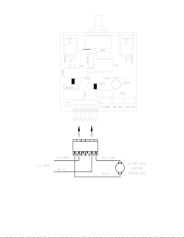
Figure 4. MM31750B/MM31751B Connections
4-WIRE HARNESS
INCLUDED
(MINARIK P/N 201–0071)

Startup
1. Turn the speed adjust potentiometer full counterclockwise
(CCW).
2. Apply 115 VAC line voltage to L1 and L2.
3. Slowly advance the speed adjust potentiometer clockwise
(CW). The motor slowly accelerates as the potentiometer is
turned CW. Continue until the desired speed is reached.
4. Remove the 115 VAC line voltage from the drive to coast the
motor to a stop.
Calibration
Each drive is factory calibrated to its maximum horsepower
rating. Readjust the calibration trimpot settings to accommodate
lower horsepower motors. Use a non-metallic screwdriver for
calibration.
MIN SPD
The MIN SPD setting determines the motor speed when the
speed adjust potentiometer is turned full CCW. To calibrate,
turn the speed adjust potentiometer full CCW. Adjust the MIN
SPD trimpot until the motor has stopped, or is running at the
desired speed.

MAX SPD
The MAX SPD setting determines the motor speed when
the speed adjust potentiometer is turned full clockwise. To
calibrate, set the MAX SPD trimpot full counterclockwise.
Turn the speed adjust potentiometer full CW. Adjust the MAX
SPD trimpot until the maximum motor speed is reached.
IR COMP
The IR COMP setting the degree to which the motor speed is
held constant as the motor load changes. If the motor does not
maintain set speed as the load changes, gradually rotate the IR
COMP trimpot CW. If the motor speed oscillates
(overcompensation), the IR COMP may be set too high. Turn
the IR COMP trimpot CCW to stabilize the motor speed.
901 East Thompson Avenue
Glendale, California 91201-2011
Phone: (818) 502-1528
Fax: (818) 502-0716
Document Number 250–0231, Revision 0
Printed in the U.S.A –9/96
U.S.A. $2.00, Outside U.S.A. $3.00
 Loading...