

Minarik Drives MM23xx1C Series Users Manual

An American Control Electronics Brand
MM23xx1C Series
USER MANUAL
MM23001C
MM23001C-Q
MM23011C
MM23011C-Q
MM23101C
MM23111C
MM23201C
MM23211C
MM23401C
MM23411C

Dear Valued Consumer:
Congratulaons on your purchase of the MM23xx1C Series
drive. This User Manual was created for you to get the most out
of your new device and assist with the inial setup. Please visit
www.minarikdrives.com to learn more about our other drives.
Thank you for choosing Minarik Drives!
No part of this document may be reproduced or transmied in any form without wrien permission
from American Control Electronics®. The informaon and technical data in this document are
subject to change without noce. American Control Electronics® makes no warranty of any kind with
respect to this material, including, but not limited to, the implied warranes of its merchantability
and tness for a given purpose. American Control Electronics® assumes no responsibility for any
errors that may appear in this document and makes no commitment to update or to keep current
the informaon in this document.
MM23xx1C Series
Safety First!
SAFETY WARNINGS
Text in gray boxes denote important safety ps or warnings.
Please read these instrucons carefully before performing any of
!
• DO NOT INSTALL, REMOVE, OR REWIRE THIS EQUIPMENT WITH
• Reduce the chance of an electrical fire, shock, or explosion by using
the procedures contained in this manual.
WARNING!
POWER APPLIED. Have a qualified electrical technician install, adjust
and service this equipment. Follow the National Electrical Code
and all other applicable electrical and safety codes, including the
provisions of the Occupational Safety and Health Act (OSHA), when
installing equipment.
proper grounding techniques, over-current protection, thermal
protection, and enclosure. Follow sound maintenance procedures.
It is possible for a drive to run at full speed as a result of a
component failure. Minarik Drives strongly recommends the
!
installaon of a master switch in the main power input to stop
WARNING!
the drive in an emergency.
Circuit potenals are at 115 VAC or 230 VAC above earth ground.
Avoid direct contact with the printed circuit board or with circuit
elements to prevent the risk of serious injury or fatality. Use a
non-metallic screwdriver for adjusng the calibraon trim pots.
Use approved personal protecve equipment and insulated tools
if working on this drive with power applied.
i

MM23xx1C Series
Table of Contents
Section 1. Specifications ..................................................... 1
Section 2. Dimensions ......................................................... 3
Section 3. Installation ....................................................... 10
Heat Sinking ................................................................................10
Mounting ....................................................................................11
Chassis ................................................................................11
Speed Adjust Potentiometer .............................................12
NEMA 1 ...............................................................................13
NEMA 4X .............................................................................14
Wiring .........................................................................................15
Shielding Guidelines.............................................................16
Line Fusing ..........................................................................17
Connections.................................................................................19
Quick-Disconnect Terminal Block ..........................................19
Power Inputs .......................................................................21
Motor ..................................................................................21
Field Output Connections .....................................................22
Speed Adjust Potentiometer .................................................23
Meter (MM230x1C-H models only) .......................................23
Analog Input Signal ..............................................................24
Section 4. Operation ......................................................... 28
Before Applying Power .................................................................28
Select Switches ............................................................................29
Input Voltage Select (SW501) ...............................................29
Armature Voltage Select (SW502) .........................................29
Startup ........................................................................................30
MM23001C, MM23001C-Q, MM23011C, MM23011C-Q..........30
MM23101C, MM23111C, MM23401C, MM23411C .................30
MM23201C and MM23211C ................................................31
Starting and Stopping Methods ....................................................32
ii

Line Starting and Stopping ...................................................32
Dynamic Braking ..................................................................33
Inhibit Terminals ..................................................................35
Decelerating to Minimum Speed ...........................................36
MM23xx1C Series
Section 5. Calibration ....................................................... 37
Minimum Speed (MIN SPD) ..........................................................38
Maximum Speed (MAX SPD) .........................................................38
Torque (TORQUE) .........................................................................39
IR Compensation (IR COMP) .........................................................40
Acceleration (ACCEL) ....................................................................42
Deceleration (DECEL) ...................................................................42
Section 6.Application Notes ............................................... 43
Multiple Fixed Speeds .................................................................. 43
Adjustable Speeds Using Potentiometers In Series .........................44
Independent Adjustable Speeds .................................................... 45
RUN/JOG Switch - Inhibit Connection ............................................46
RUN/JOG Switch - Potentiometer Connection ................................47
Leader-Follower Application .........................................................48
Single Speed Potentiometer Control Of Multiple Drives .................49
Reversing .....................................................................................50
Section 7. Diagnostic LEDs ................................................. 51
Section 8. Troubleshooting ................................................ 52
Before Troubleshooting ................................................................52
Section 9. Block Diagrams ................................................. 55
Section 10. Accessories & Replacement Parts...................... 58
Unconditional Warranty ..................................................... 59
iii

MM23xx1C Series
List of Tables
Table 1 Recommended Line Fuse Sizes ..........................................18
Table 2 Short Circuit Current Ratings ............................................18
Table 3 Field Output Connections .................................................22
Table 3 Minimum Recommended Dynamic Brake Resistor Values ...34
iv

MM23xx1C Series
List of Figures
Figure 1 MM23001C and MM23011C Dimensions ............................ 3
Figure 2 MM23001C-Q and MM23011C-Q Dimensions ..................... 4
Figure 3 MM23101C and MM23111C Dimensions ............................ 5
Figure 4 MM23201C and MM23211C Dimensions ............................ 6
Figure 5 MM23401C and MM23411C Dimensions ............................ 7
Figure 6 223-0159 Dimensions ........................................................ 8
Figure 7 223-0174 Dimensions ........................................................ 9
Figure 8 Speed Adjust Potentiometer .............................................12
Figure 9 Quick-Disconnect Terminal Block ......................................20
Figure 10 Analog Input Signal Connections .......................................24
Figure 11 Chassis Drive Connections ................................................ 25
Figure 12 MM23001C-Q and MM23011C-Q Connections ...................26
Figure 13 Cased Drive Connections .................................................. 27
Figure 14 Select Switches ................................................................29
Figure 15 Dynamic Brake Wiring ......................................................34
Figure 16 Inhibit Terminals ..............................................................35
Figure 17 Run/Decelerate to Minimum Speed Switch ........................36
Figure 18 Recommended TORQUE and IR COMP Settings ..................41
Figure 19 Multiple Fixed Speeds ......................................................43
Figure 20 Adjustable Speeds Using Potentiometers in Series .............44
Figure 21 Independent Adjustable Speeds ........................................45
Figure 22 RUN/JOG Switch - Inhibit Connection ................................46
Figure 23 RUN/JOG Switch - Potentiometer Connection ....................47
Figure 24 Leader-Follower Application .............................................48
Figure 25 Single Speed Potentiometer Control of Multiple Drives ......49
Figure 26 Reversing Circuit Wiring ...................................................50
Figure 27 Diagnostic LED Locations .................................................. 51
Figure 28 MM23xx1C Series Block Diagram ......................................55
v

MM23xx1C Series
Figure 29 MM23101C, MM23111C, MM23401C, and MM23411C
Figure 30 MM23201C and MM23211C Terminal Block Connections ...57
Terminal Block Connections ..............................................56
vi

Section 1. Specifications
MM23xx1C Series
Model
MM23011C
MM23111C
MM23211C
MM23411C
MM23072A
MM23001C*
MM23101C**
MM23201C**
MM23401C
MM23071A*
Maximum
Armature
Current (ADC)
1.5 1/20 - 1/8 1/10 - 1/4 Chassis
10.0 1/8 - 1 1/4 - 2 Chassis
HP Range
with 90 VDC
Motor
HP Range
with 180 VDC
Motor Enclosure
NEMA 1
NEMA 1
NEMA 4X
Chassis
NEMA 1
NEMA 1
NEMA 4X
Chassis
* Heat sink kit part number 223-0159 must be used when the connuous
current output is over 5 amps.
** Heat sink kit part number 223-0174 must be used when the connuous
current output is over 5 amps.
AC Line Voltage
DC Armature Voltage
with 115 VAC Line Voltage
with 230 VAC Line Voltage
Field Voltage
with 115 VAC Line Voltage
with 230 VAC Line Voltage
Maximum Field Current 1 ADC
Acceleraon Time Range
for 0 - 90 VDC Armature Voltage
for 0 - 180 VDC Armature Voltage
Deceleraon Time Range
for 0 - 90 VDC Armature Voltage
for 0 - 180 VDC Armature Voltage
50 VDC (F1 to L1); 100 VDC (F1 to F2)
100 VDC (F1 to L1); 200 VDC (F1 to F2)
115/230 VAC ± 10%
50/60 Hz, single phase
0 - 90 VDC
0 - 180 VDC
0.5 - 11 seconds
0.5 - 22 seconds
coast to a stop - 13 seconds
coast to a stop - 25 seconds
1

MM23xx1C Series
Deceleraon Time Range
for 0 - 90 VDC Armature Voltage
for 0 - 180 VDC Armature Voltage
Analog Input Range
(signal must be isolated; S1 to S2)
with 115 VAC Line Voltage
with 230 VAC Line Voltage
Input Impedance (S1 to S2) >100K ohms
Form Factor 1.37 at base speed
Load Regulaon 1% base speed or beer
Speed Range 60:1
Vibraon 0.5G maximum (0 - 50 Hz)
Safety Cercaons UL/cUL Listed Equipment, File # E132235
Ambient Temperature Range
Chassis Drive
Cased Drive
UL/cUL Overload Protecon (except -Q models)
CSA Cered Component, File # LR41380
coast to a stop - 13 seconds
coast to a stop - 25 seconds
0.1G maximum (> 50 Hz)
Sux Denions
-H: Basic Drive with Inhibit Style Connector for Meter
-Q: Basic Drive with Power LED and Quick Disconnect
MM2307xA: Basic Drive with Power LED and Vercal Trim Pots
Terminal Block
0 - 1.4 VDC
0 - 2.8 VDC
10°C - 55°C
10°C - 40°C
2
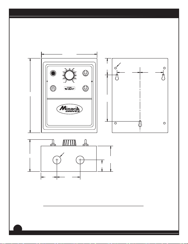
Section 2. Dimensions
MM23xx1C Series
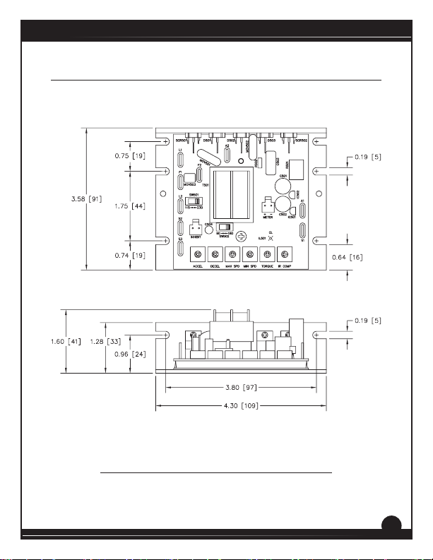
ALL DIMENSIONS IN INCHES [MILLIMETERS]
Figure 1. MM23001C and MM23011C Dimensions
3
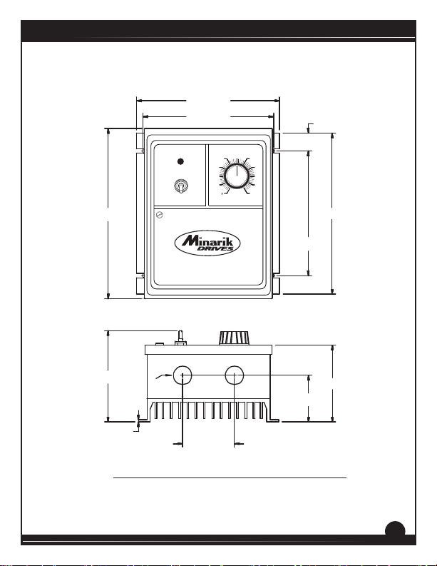
MM23xx1C Series
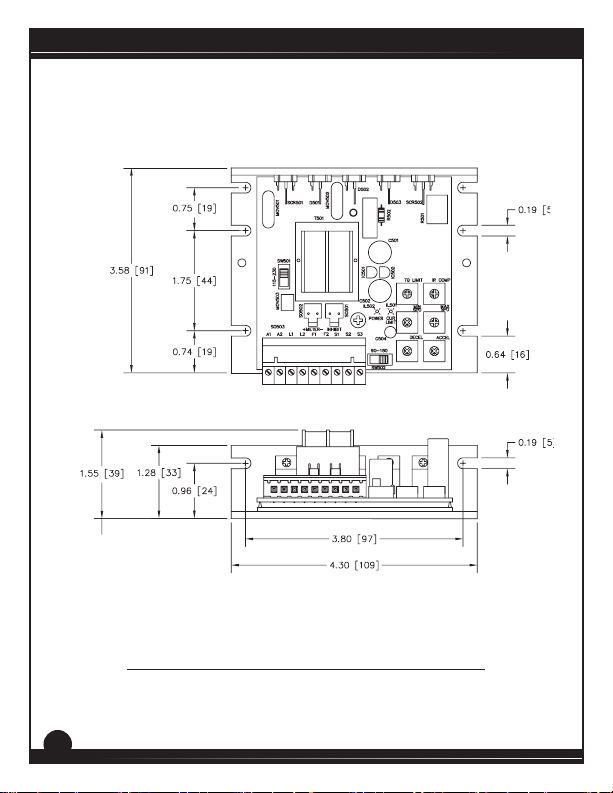
ALL DIMENSIONS IN INCHES [MILLIMETERS]
Figure 2. MM23001C-Q and MM23011C-Q Dimensions
4
MM23xx1C Series
6.00 [125]
Ø 0.19
C
[5] (4)
2.50
[64]
L
2.50
[64]
8.00
[203]
MADE IN U.S.A.
South Beloit, IL
SPEED
50
40
30
20
10
POWER
ON
OFF
WARNING: DISCONNECT FROM SUPPLY BEFORE OPENING THIS COVER.
SEPARATE MOTOR OVERCURRENT AND OVERLOAD PROTECTION IN ACCORDANCE WITH
THE CANADIAN ELECTRICAL CODE PART 1 IS PROVIDED BY OTHERS.
1.79
[45]
60
70
80
90
100
5.00
[127]
3.46
[88]
Ø 0.88
[22] (2)
1.25 [32]
1.72
[44]
2.50
[64]
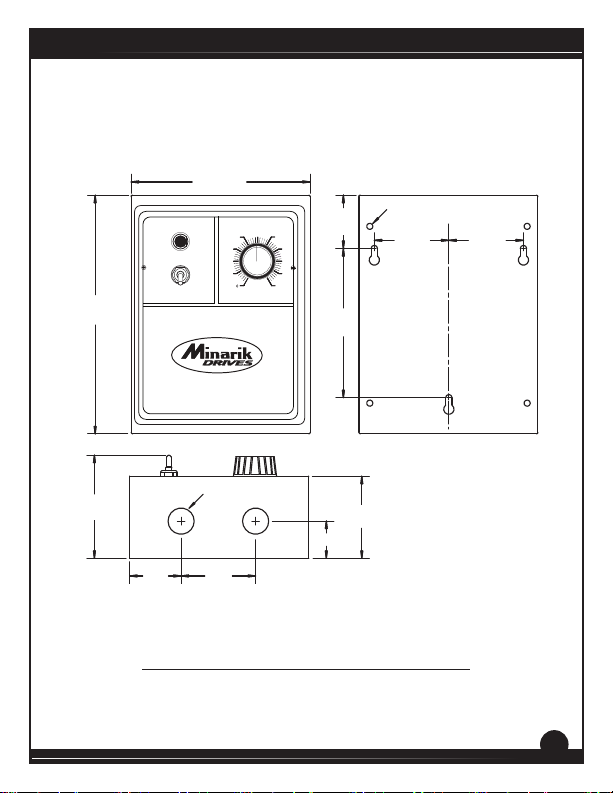
ALL DIMENSIONS IN INCHES [MILLIMETERS]
Figure 3. MM23101C and MM23111C Dimensions
2.75
[70]
5
MM23xx1C Series
8.00 [203]
3.46 [88]
6.00 [125]
50
60
40
POWER
ON
OFF
WARNING: DISCONNECT FROM SUPPLY BEFORE OPENING THIS COVER.
SEPARATE MOTOR OVERCURRENT AND OVERLOAD PROTECTION IN ACCORDANCE WITH
THE CANADIAN ELECTRICAL CODE PART 1 IS PROVIDED BY OTHERS.
30
20
10
WARNING!
ALLOW MOTOR TO STOP
BEFORE REVERSING
MADE IN U.S.A.
South Beloit, IL
Ø 0.88
[22] (2)
70
80
90
100
RUN
BRAKE
FORWARD
REVERSE
1.25 [32]
1.79
[45]
5.00
[127]
2.75
[70]
Ø 0.19
[5] (4)
2.50
[64]
C
L
2.50
[64]
1.72
[44]
2.50
[64]
ALL DIMENSIONS IN INCHES [MILLIMETERS]
Figure 4. MM23201C and MM23211C Dimensions
6
MM23xx1C Series
6.90 [175]
6.30 [160]
0.87 [22]
POWER
ON
OFF
SPEED
50
60
40
70
30
80
20
90
10
100
8.20 [208]
MADE IN U.S.A.
South Beloit, IL
WARNING: DISCONNECT FROM SUPPLY BEFORE OPENING THIS COVER.
SEPARATE MOTOR OVERCURRENT AND OVERLOAD PROTECTION IN ACCORDANCE WITH
THE CANADIAN ELECTRICAL CODE PART 1 IS PROVIDED BY OTHERS.
4.50 [114]
Ø 0.88
[22] (2)
0.13 [3]
2.50 [64]
ALL DIMENSIONS IN INCHES [MILLIMETERS]
Figure 5. MM23401C and MM23411C Dimensions
7.76 [197]
6.00 [152]
3.70 [94]
2.25 [57]
7
]
]
]
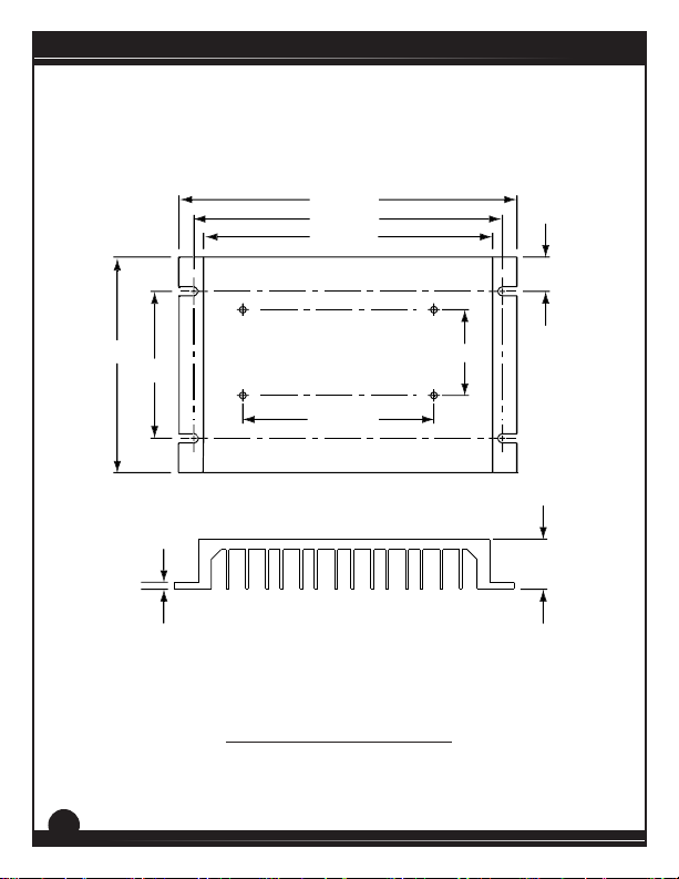
MM23xx1C Series
6.90 [ 17 5
6.30 [ 16 0
5.90 [ 150
0.7 [18]
8
4.40 [112]
3.00 [76]
0.125 [3]
1.75 [44]
3.90 [100]
1.00 [26]
ALL DIMENSIONS IN INCHES [MILLIMETERS]
Figure 6. 223-0159 Dimensions
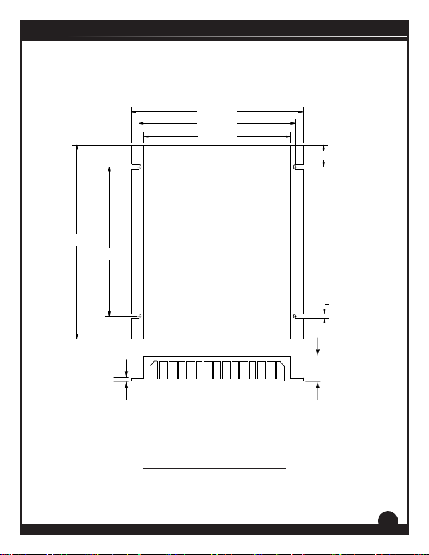
6.90 [175]
6.29 [160]
5.90 [150]
7.80 [198]
6.00 [152]
MM23xx1C Series
0.90 [23]
0.19 [5]
0.125 [3]
ALL DIMENSIONS IN INCHES [MILLIMETERS]
Figure 7. 223-0174 Dimensions
1.00 [26]
9
MM23xx1C Series
Section 3. Installation
Do not install, rewire, or remove this control with input power
applied. Failure to heed this warning may result in re, explosion,
!
Heat Sinking
Chassis
Models MM23001C and MM23001C-Q require an addional heat sink
when the connuous armature current is above 5 amps. Use heat sink
kit part number 223-0159. All other chassis drives have sucient heat
sinking in their basic conguraon. Use a thermally conducve heat sink
compound (such as Dow Corning® 340 Heat Sink Compound) between
the chassis and the heat sink surface for opmum heat transfer.
NEMA 1
Models MM23101C and MM23201C require an addional heat sink
when the connuous armature current is above 5 amps. Use heat sink
kit part number 223-0174. All other NEMA 1 drives have sucient heat
sinking in their basic conguraon. Use a thermally conducve heat sink
compound (such as Dow Corning® 340 Heat Sink Compound) between
the chassis and the heat sink surface for opmum heat transfer.
NEMA 4X
All NEMA 4X models come with the heat sink already aached.
Therefore, all NEMA 4X drives have sucient heat sinking in their basic
conguraon.
or serious injury. Make sure you read and understand the Safety
WARNING!
Precauons on page i before aempng to install this product.
10

MM23xx1C Series
Mounng
Chassis
• Drive components are sensitive to electrostatic discharge. Avoid
direct contact with the circuit board. Hold the drive by the chassis
or heat sink only.
• Protect the drive from dirt, moisture, and accidental contact.
• Provide sufficient room for access to the terminals and calibration
trim pots.
• Mount the drive away from heat sources. Operate the drive within
the specified ambient operating temperature range.
• Prevent loose connections by avoiding excessive vibration of the
drive.
• Mount the drive with its board in either a horizontal or vertical
plane. Eight 0.19” (5 mm) wide slots in the chassis accept #8 pan
head screws. Fasten either the large base or the narrow flange of
the chassis to the subplate.
• The chassis should be earth grounded. Use a star washer beneath
the head of at least one of the mounting screws to penetrate the
anodized surface and to reach bare metal.
11
MM23xx1C Series
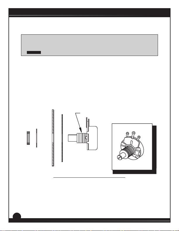
Speed Adjust Potenometer
Be sure that the potenometer tabs do not make contact with the
potenometer’s body. Grounding the input will cause damage to
!
If using a remote potenometer with a chassis drive, mount the speed
adjust potenometer through a 0.38 in. (10 mm) hole with the hardware
provided (Figure 8). Install the circular insulang disk between the panel
and the 10K ohm speed adjust potenometer.
Twist the speed adjust potenometer wire to avoid picking up unwanted
electrical noise. If the speed adjust potenometer wires are longer than
18 in. (46 cm), use shielded cable. Keep the speed adjust potenometer
wires separate from power leads (L1, L2, A1, A2, F1, F2).
NUT
WARNING!
STAR
WASHER
the drive.
MOUNT THROUGH A 0.38 IN. (10 MM) HOLE
SPEED ADJUST
POTENTIOMETER
INSULATING DISK
PANEL
Figure 8. Speed Adjust Potenometer
CW
POT TAB ASSIGNMENTS
WIPER
CCW
12

MM23xx1C Series
Mounng (NEMA 1 Enclosures)
NEMA 1 cased drives come with two 0.88 inch (22 mm) conduit holes
at the boom of the case. The units may be vercally wall mounted or
horizontally bench mounted using the three keyholes on the back of the
case.
1. For access to the keyholes and the terminal strip, remove
the two screws from the front of the case by turning them
counterclockwise. Grasp the front cover and pull it straight out.
2. Install the mounting screws in the three keyholes.
3. Set the POWER switch to the OFF position before applying the
AC line voltage.
4. Install conduit hardware through the conduit holes at the
bottom of the case. Connect external wiring to the terminal
block.
5. Reinstall the front cover. Avoid pinching any wires between the
front cover and the case.
6. Reinstall the two screws on the front cover. Turn the screws
clockwise to tighten.
13
 Loading...