

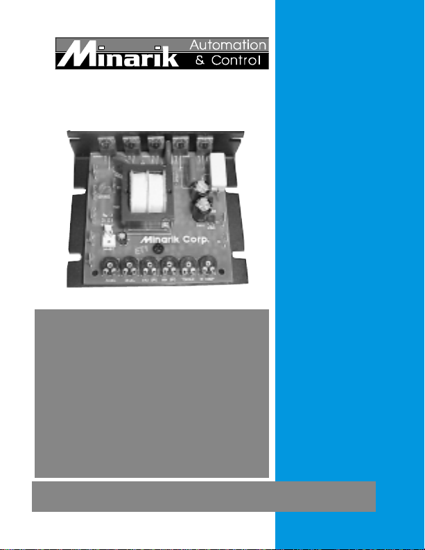
Minarik Drives MM20000 Series Users Manual
MM20000 Series
Models:
MM21000A
MM21001A
MM21010A
MM21011A
MM22000A
MM22001A
MM22011A
User’s Manual
SCR, Adjustable Speed Drives for DC Brush Motors

Copyright © 2001 by
Minarik Corporation
All rights reserved. No part of this manual may be reproduced or
transmitted in any form without written permission from Minarik
Corporation. The information and technical data in this manual are
subject to change without notice. Minarik Corporation and its Divisions
make no warranty of any kind with respect to this material, including,
but not limited to, the implied warranties of its merchantability and
fitness for a given purpose. Minarik Corporation and its Divisions
assume no responsibility for any errors that may appear in this manual
and make no commitment to update or to keep current the information
in this manual.
Printed in the United States of America.

Safety Warnings
• This symbol denotes an important safety tip or warning.
Please read these instructions carefully before performing any
of the procedures contained in this manual.
• DO NOT INSTALL, REMOVE, OR REWIRE THIS
EQUIPMENT WITH POWER APPLIED. Have a qualified
electrical technician install, adjust and service this equipment.
Follow the National Electrical Code and all other applicable
electrical and safety codes, including the provisions of the
Occupational Safety and Health Act (OSHA), when installing
equipment.
• Reduce the chance of an electrical fire, shock, or explosion by
proper grounding, over-current protection, thermal protection, and
enclosure. Follow sound maintenance procedures.
It is possible for a drive to run at full speed as a result
of a component failure. Minarik strongly recommends
the installation of a master switch in the main power input
to stop the drive in an emergency.
Circuit potentials are at 115 VAC or 230 VAC above
earth ground. Avoid direct contact with the printed
circuit board or with circuit elements to prevent the risk of
serious injury or fatality. Use a non-metallic screwdriver
for adjusting the calibration trimpots. Use approved
personal protective equipment and insulated tools if
working on this drive with power applied.
i

ii
Contents
Specifications 1
Dimensions 2
Installation 4
Mounting ..............................................4
Wiring.................................................5
Shieldingguidelines ....................................6
Speed adjust potentiometer connections .......................7
Heatsinking ............................................8
Linefusing .............................................8
Connections ............................................9
Motor connections .....................................9
Power connections ...................................10
Line fuse connections .................................10
Field output connections ................................10
Voltage follower connection .............................13
Operation 14
Before applying power ...................................14
Drive startup and shutdown ...............................14
Toshutdownthedrive: ................................15
Reversing ..........................................15
Starting and Stopping Methods .............................15
Line starting and stopping ..............................16
Decelerating to minimum speed ..........................16
Coast to minimum speed using INHIBIT terminals ............17
Dynamic braking ......................................18
Calibration 20
Calibration procedure ....................................22
MINIMUM SPEED (MIN SPD) ...........................22
MAXIMUM SPEED (MAX SPD) ..........................23

ACCELERATION (ACCEL) .............................23
DECELERATION (DECEL) .............................24
REGULATION (IR COMP) ..............................25
TORQUE LIMIT (TORQUE) .............................26
Application Notes 28
FWD-STOP-REVswitch ..................................28
Reversing with dynamic braking ............................29
Reversing with a DLC600 .................................30
Independent adjustable speeds ............................31
Adjustable speeds using potentiometers in series ...............32
Multiple fixed speeds ....................................33
RUN/JOG switch .......................................34
Leader-follower application ................................35
Single speed potentiometer control of multiple drives ............36
Troubleshooting 37
Before troubleshooting ...................................37
ReplacementParts ......................................41
Certificate of Compliance 43
Exhibit“A” ............................................44
Unconditional Warranty inside back cover
iiiContents

iv
Illustrations
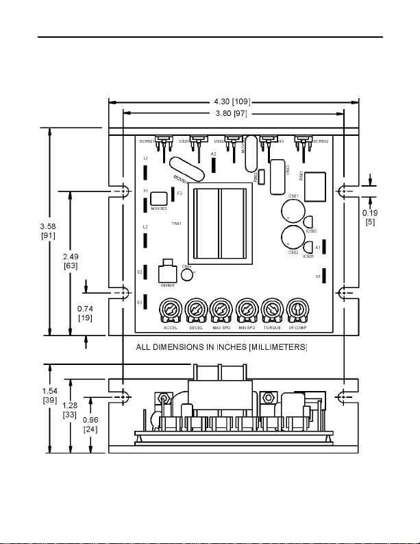
Figure 1. Dimensions ........................................2
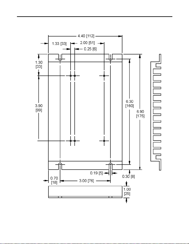
Figure 2. 223-0159 Heat Sink Dimensions .........................3
Figure 3. Speed Adjust Potentiometer Installation ...................7
Figure 4. Power, Fuse and Motor Connections ....................12
Figure 5. Voltage Follower Connections ..........................13
Figure 6. Run / Decelerate to Minimum Speed Switch ...............16
Figure 7. RUN / Coast to Minimum Speed Switch ..................17
Figure 8. Dynamic Brake Connection ...........................19
Figure 9. Calibration Trimpot Layout ............................21
Figure 10. Typical IR COMP and TORQUE Settings .................27
Figure11. FWD-STOP-REVSwitch..............................28
Figure 12. Reversing Circuit Connection ..........................29
Figure 13. Reversing with a DLC600 .............................30
Figure 14. Independent Adjustable Speeds .......................31
Figure 15. Adjustable Fixed Speeds Using Potentiometers in Series .....32
Figure 16. Multiple Fixed Speeds ...............................33
Figure 17. RUN/JOG Switch Connection to Speed Adjust Potentiometer . .34
Figure 18. Leader-Follower Application ...........................35
Figure 19. Single Speed Potentiometer Control of Multiple Drives .......36

Tables
Table 1. Replacement Line Fuse Sizes ..........................8
Table 2. Field Output Connections ............................11
Table 3. Recommended Dynamic Brake Resistor Sizes ............18
Table4. ReplacementParts .................................41
Table 5. Corcom Filters .....................................44
Table6. MinarikFilters .....................................45
v
vi
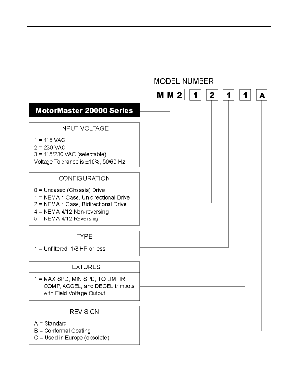
MM20000 Series Numbering System

Specifications
Max. Max.
Input Input Armature
Voltage Current Current HP
Model (AC) (Amps AC) (Amps DC) Range Style
MM21000A 115 3 5* 1/8 – 1/2* Chassis
MM21001A 115 3 5* 1/8 – 1/2* Chassis
MM21010A 115 3 1.5 1/20 – 1/8 Chassis
MM21011A 115 3 1.5 1/20 – 1/8 Chassis
MM22000A 230 3 5** 1/4 – 1** Chassis
MM22001A 230 3 5** 1/4 – 1** Chassis
*Max HP = 1 and max armature current = 10A if mounted on 223-0159 heat
sink.
**Max HP = 2 and max armature current = 10A if mounted on 223-0159 heat
sink.
AC Line Voltage Tolerance ±10%, 50/60 Hz, single phase
Armature Voltage
115 VAC line voltage 0 – 90 VDC
230 VAC line voltage 0 – 180 VDC
Field Voltage (1 ADC max) 50 – 100 VDC
Maximum Output Field Current 1 ADC
Form Factor 1.37 at base speed
Accel. Time Range 0.5 – 11 seconds
Decel. Time Range coast to a stop – 13 seconds
Analog Input Voltage Range (signal must be isolated; S1 to S2)
0–90VDCMotors 0–1.4VDC
0 – 180 VDC Motors 0 – 2.8 VDC
Input Impedance (S1 to S2) 100K ohms
Load Regulation 1% base speed or better
Vibration 0.5G max (0 – 50 Hz)
0.1G max (>50 Hz)
Ambient Temp. Range 10°C – 55°C
1
2
Dimensions
Figure 1. Dimensions
3Dimensions
ALL DIMENSIONS IN INCHES [MILLIMETERS]
Figure 2. 223-0159 Heat Sink Dimensions

4
Installation
Mounting
Warning
Do not install, rewire, or remove this control with
power applied. Doing so may cause fire or serious injury.
Make sure you have read and understood the Safety
Warnings on page i before attempting installation.
The chassis must be earth grounded. Use a star washer
beneath the head of at least one of the mounting screws to
penetrate the anodized chassis surface and to reach bare
metal.
• Drive components are sensitive to electrostatic fields. Avoid
direct contact with the circuit board. Hold drive by the
chassis only.
• Protect the drive from dirt, moisture, and accidental contact.
Provide sufficient room for access to the terminal block and
calibration trimpots.
• Mount the drive away from heat sources. Operate the drive
within the specified ambient operating temperature range.
• Prevent loose connections by avoiding excessive vibration of
the drive.

Wiring
Warning
Do not install, remove, or rewire this equipment with
Ꮨ
power applied. Failure to heed this warning may result in
fire, explosion, or serious injury.
Circuit potentials are at 115 or 230 VAC above ground.
To prevent the risk of injury or fatality, avoid direct
contact with the printed circuit board or with circuit
elements.
Do not disconnect any of the motor leads from the drive
unless power is removed or the drive is disabled. Opening
any one motor lead may destroy the drive.
Use 18–24 AWG wire for speed adjust potentiometer wiring.
Use 14–16 AWG wire for AC line (L1, L2), field (F1, F2) and
motor (A1, A2) wiring.
5Installation

6 Installation
Shielding guidelines
Warning
Under no circumstances should power and logic leads be
bundled together. Induced voltage can cause
unpredictable behavior in any electronic device, including
motor controls.
As a general rule, Minarik recommends shielding of all
conductors.
If it is not practical to shield power conductors, Minarik
recommends shielding all logic-level leads. If shielding logic
leads is not practical, the user should twist all logic leads with
themselves to minimize induced noise.
It may be necessary to earth ground the shielded cable. If noise
is produced by devices other than the drive, ground the shield
at the drive end. If noise is generated by a device on the drive,
ground the shield at the end away from the drive. Do not
ground both ends of the shield.
If the drive continues to pick up noise after grounding the
shield, it may be necessary to add AC line filtering devices, or
to mount the drive in a less noisy environment.
Speed adjust potentiometer connections
Warning
Be sure that the potentiometer tabs do not make contact
with the potentiometer enclosure. Grounding the input will
cause damage to the drive.
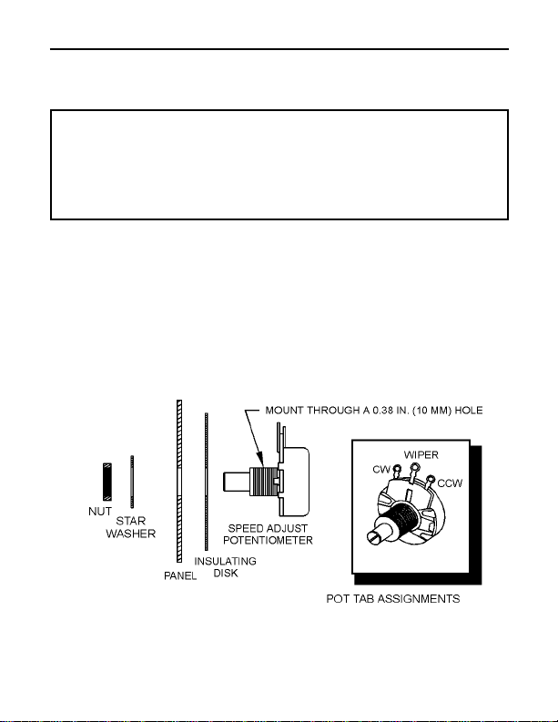
Install the circular insulating disk between the mounting panel
and the 10K ohm speed adjust potentiometer (see Figure 3).
Mount the speed adjust potentiometer through a 0.38-inch
(10 mm) hole with the hardware provided. Twist the speed
adjust potentiometer wires to avoid picking up unwanted
electrical noise.
7Installation
Figure 3. Speed Adjust Potentiometer Installation

8 Installation
Heat sinking
MM20000-series drives require an additional heat sink, p/n
223-0159, when the continuous armature current is above 5
ADC. Apply a thermally conductive heat sink compound (such
as Dow Corning® 340 Heat Sink Compound) between the
drive chassis and heat sink surface for optimum heat transfer.
Line fusing
Minarik drives require an external fuse for protection. Use fast
acting fuses rated for 250 VAC or higher. Table 1 lists the
recommended line fuse sizes.
Table 1. Replacement Line Fuse Sizes
90 VDC Motor 180 VDC Max. DC Armature AC Line Fuse
Horsepower Horsepower Current (amps) Size (amps)
1/20 1/10 0.5 1
1/15 1/8 0.8 1.5
1/8 1/4 1.5 3
1/6 1/3 1.7 3
1/4 1/2 2.6 5
1/3 3/4 3.5 8
1/2 1 5.0 10
3/4 1 1/2 7.6 15
1 2 10 15
Minarik Corporation offers two fuse kits: part number
050–0066 (1–5A Fuse Kit) and 050–0071 (5–15A Fuse Kit).
See Replacement Parts (page 41) for fuse kit contents.

Connections
Warning
Do not connect this equipment with power applied.
Failure to heed this directive may result in fire or serious
injury.
Minarik strongly recommends the installation of a master
power switch in the voltage input line. The switch
contacts must be rated at a minimum of 200% of motor
nameplate current and 250 volts.
Connect the power input leads, field output, external line
fuse(s) and DC motor to the drive’s printed circuit board (PCB)
as shown in Figure 4 (page 12).
Motor connections
Minarik drives supply motor voltage from A1 and A2
terminals. It is assumed throughout this manual that, when A1
is positive with respect to A2 , the motor will rotate clockwise
(CW) while looking at the output shaft protruding from the
front of the motor. If this is opposite of the desired rotation,
simply reverse the wiring of A1 and A2 with each other.
9Installation
Connect a DC motor to PCB terminals A1 and A2 as shown in
Figure 4 (page 12). Ensure that the motor voltage rating is
consistent with the drive’s output voltage.
 Loading...