

Minarik Drives MDVF05-D230-PCM Quick Start Guide
MDVF05-D230-PCM
205
Chassis, Microprocessor-based
Variable Frequency Drive with Isolation
for Single and Three Phase AC Motors
Specifications
Line
Model
MDVF03-D230-PCM
* When mounted to allow upwards airflow through the heat sink fins.
* De-rate to 4.0 amps when mounted in any other configuraon.
AC Line Voltage
Output Frequency Range
Form Factor
Acceleraon Time Range (0 - 60 Hz)
Deceleraon Time Range (60 - 0 Hz)
Adjustable DC Injecon Voltage
Adjustable DC Injecon Voltage Time
Analog Input Voltage Range (S1 to S2)
Analog Input Current Range (S1 to S2)
Input Impedance (S1 to S2)
Load Regulaon
Speed Range
Vibraon (0 - 50 Hz)
(>50 Hz)
Ambient Temperature Range
Weight
......................................................115/230 VAC ± 10%, 50/60 Hz, single phase
..........................................................................................................................1.05
...................................................................................1% base speed or beer
.......................................................................................................................100:1
..............................................................................................................................2.5 lbs
Voltage
(VAC)
115 or 230
............................................................................................0 - 120 Hz
................................................................................0 - 27 VDC
.......................................................................................>50K ohms
...........................................................................................0.5G maximum
..............................................................................................0.1G maximum
.....................................................................................0°C - 40°C
Motor
Voltage Range
(VDC)
0 - 115
0 - 230
.................................................................0.5 - 12 seconds
................................................................0.5 - 12 seconds
...................................................................0 - 5 seconds
........................................................0 - 5; 0 to ± 10 VDC
........................................................................4 - 20 mA
Connuous
Motor
Current (Amps)
5.0*
Horsepower
Range
1/16 - 3/4
1/8 - 1 1/2
Installation
Mounng
• Drive components are sensive to electrostac discharge. Avoid direct contact with the circuit
• board. Hold the drive by the plate only.
• Protect the drive from dirt, moisture, and accidental contact.
• Provide sufficient room for access to the terminals and calibraon trim pots.
• Mount the drive away from heat sources. Operate the drive within the specified ambient operang
• temperature range.
• Prevent loose connecons by avoiding excessive vibraon of the drive.
• Mount the drive with its board in either a horizontal or vercal plane. Six 0.17” (4 mm) holes in the
• plate accept #8 pan head screws. If mounted horizontally, the drive must be de-rated to 2.5 amps.
• The plate should be earth grounded.
Wiring
Use 18 - 24 AWG wire for logic wiring. Use 14 - 16 AWG wire for AC line and motor wiring.
Shielding Guidelines
As a general rule, Minarik Drives recommends shielding of all conductors. If it is not praccal to shield
power conductors, Minarik Drives recommends shielding all logic-level leads. If shielding of logic-level
leads is not praccal, the user should twist all logic leads with themselves to minimize induced noise.
It may be necessary to earth ground the shielded cable. If noise is produced by devices other than the
drive, ground the shield at the drive end. If noise is generated by the drive, ground the shield at the
end away from the drive. Do not ground both ends of the shield.
Fusing
Minarik Drives drives require an external line fuse for protecon. Use fast acng fuses rated for 250
VAC or higher and 150% of the maximum armature current. Fuse the HOT leg of the AC line when
using 115 VAC and both lines when using 230 VAC.
Safety Warnings
READ ALL SAFETY WARNINGS BEFORE INSTALLING THIS EQUIPMENT
• DO NOT INSTALL, REMOVE, OR REWIRE THIS EQUIPMENT WITH POWER APPLIED. Have a
• qualified electrical technician install, adjust and service this equipment. Follow the Naonal
• Electrical Code and all other applicable electrical and safety codes, including the provisions of the
• Occupaonal Safety and Health Act (OSHA), when installing equipment.
• Circuit potenals are at 115 or 230 VAC above earth ground. Avoid direct contact with the printed
• circuit board or with circuit elements to prevent the risk of serious injury or fatality. Use a non-
• metallic screwdriver for adjusng the calibraon trim pots. Use approved personal protecon
• equipment and insulated tools if working on this drive with power applied.
• Reduce the chance of an electrical fire, shock, or explosion by using proper grounding techniques,
• over-current protecon, thermal protecon, and enclosure. Follow sound maintenance procedures.
• Minarik Drives strongly recommends the installaon of a master power switch in the line voltage
• input. The switch contacts should be rated for 250 VAC and 200% of motor nameplate current.
• Removing AC line power is the only acceptable method for emergency stopping. Do not use
• DC injecon braking, decelerang to minimum speed, or coasng to a stop for emergency stopping.
• They may not stop a drive that is malfunconing. Removing AC line power is the only acceptable
• method for emergency stopping.
• Line starng and stopping (applying and removing AC line voltage) is recommended for infrequent
• starng and stopping of a drive only. DC injecon braking, decelerang to minimum speed, or
• coasng to a stop is recommended for frequent starts and stops. Frequent starng and stopping can
• produce high torque. This may cause damage to motors.
• Do not disconnect any of the motor leads from the drive unless power is removed or the drive is
• disabled. Opening any one lead while the drive is running may destroy the drive.
• Under no circumstances should power and logic level wires be bundled together.
• Be sure potenometer tabs do no make contact with the potenometer’s body. Grounding the
• input will cause damage to the drive.
• Only connect to terminal L2-DBL if using a 115 VAC line with a motor rated higher than 115 VAC.
• Cauon should be taken when operang fan-cooled motors at low speeds because their fans may
• may not move sufficient air to properly cool the motor. ACE recommends “inverter-duty” motors
• when the speed range is beyond 10:1.
• Drive is designed to work with permanent split capacitor, shaded pole, and standard three phase
• inducon motors. In general, the drive can work with capacitor-start motors, but it is condional
• on the current pull when the capacitor is in effect and how long the applicaon calls for a speed that
• the capacitor will stay in the auxiliary winding.
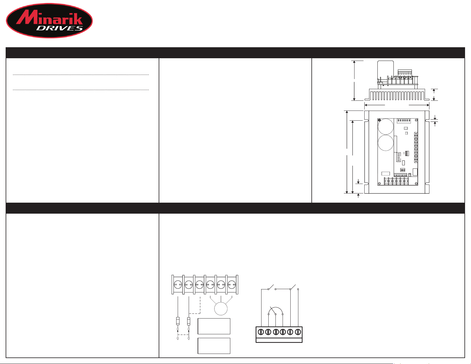
7.200 [183]
Dimensions
3.44 [87]
6.350
[161]
0.850
[22]
ALL DIMENSIONS IN INCHES [MILLIMETERS]
5.625 [143]
TB501
L1 L2/230 L2/115 U V W
1.00 [25]
315
2
4
6
7 9
8 10
IL1
IL2
J502
SW501
J503
TB502
T
205B
0.188 [5]
Connections
Line Input Speed Potenometer
If using a 115 VAC line with a 115 VAC motor or a 230 VAC line with a 115 or 230 VAC motor, connect Use a 10K ohm, 1/4 W potenometer for speed control. Connect the counter-clockwise end of the
to terminals L1 and L2. If using a 115 VAC line with a 230 VAC motor, connect to terminals L1 and potenometer to S1, wiper to S2, and the clockwise end to S3. If the potenometer works
L2-DBL. Minarik Drives recommends the use of a double-pole, single-throw master power switch. inversely of desired funconality, (i.e. to increase motor speed, you must turn the potenometer
The switch should be rated at a minimum of 250 VAC and 200% of motor current. counterclockwire), power off the drive and swap the S1 and S3 connecons.
Motor Analog Input Signal Range
Connect the motor leads to terminals U/A2, V/A1, and W. Instead of using a speed adjust potenometer, MDVF-PCM series drives may be wired to follow an
analog input signal. This input signal can be in the form of voltage (0-5, 0 to ±10 VDC) or current
(4-20 mA). Because these drives have built in isolaon, the input signal can be grounded or
ungrounded (floang). Connect the signal common (-) to S1 and the signal reference (+) to S2. See the
Operaons secon for jumper sengs.
Enable
Short terminals EN and COM to accelerate the motor to set speed. Open the ENABLE terminals to coast
the motor to zero speed. If no ENABLE switch is desired, wire a jumper between terminals COM and EN.
Do not use the enable for emergency stopping.
L1 L2 L2-DBL U/A2 V/A1 W
Direcon
Short terminals DIR and COM to change the direcon of the motor. If no direcon switch is desired,
leave this connecon open.
STOP
SWITCH
FUSE
115 / 230 VAC
AC LINE
VOLTAGE
*FUSE
MOTOR
*Fusing L2 or L2-DBL
is NOT required if
using a 115 VAC line.
NOTE: DO NOT make
any connections to
terminal L2-DBL if using
a 230 VAC line.
T
B
DIRECTION
SWITCH
10K OHM
SPEED ADJUST
POTENTIOMETER
CW
S3S2S1
DIR
ENABLE
SWITCH
COM
EN
LOGIC (TOP BOARD) POWER (BOTTOM BOARD)
Startup
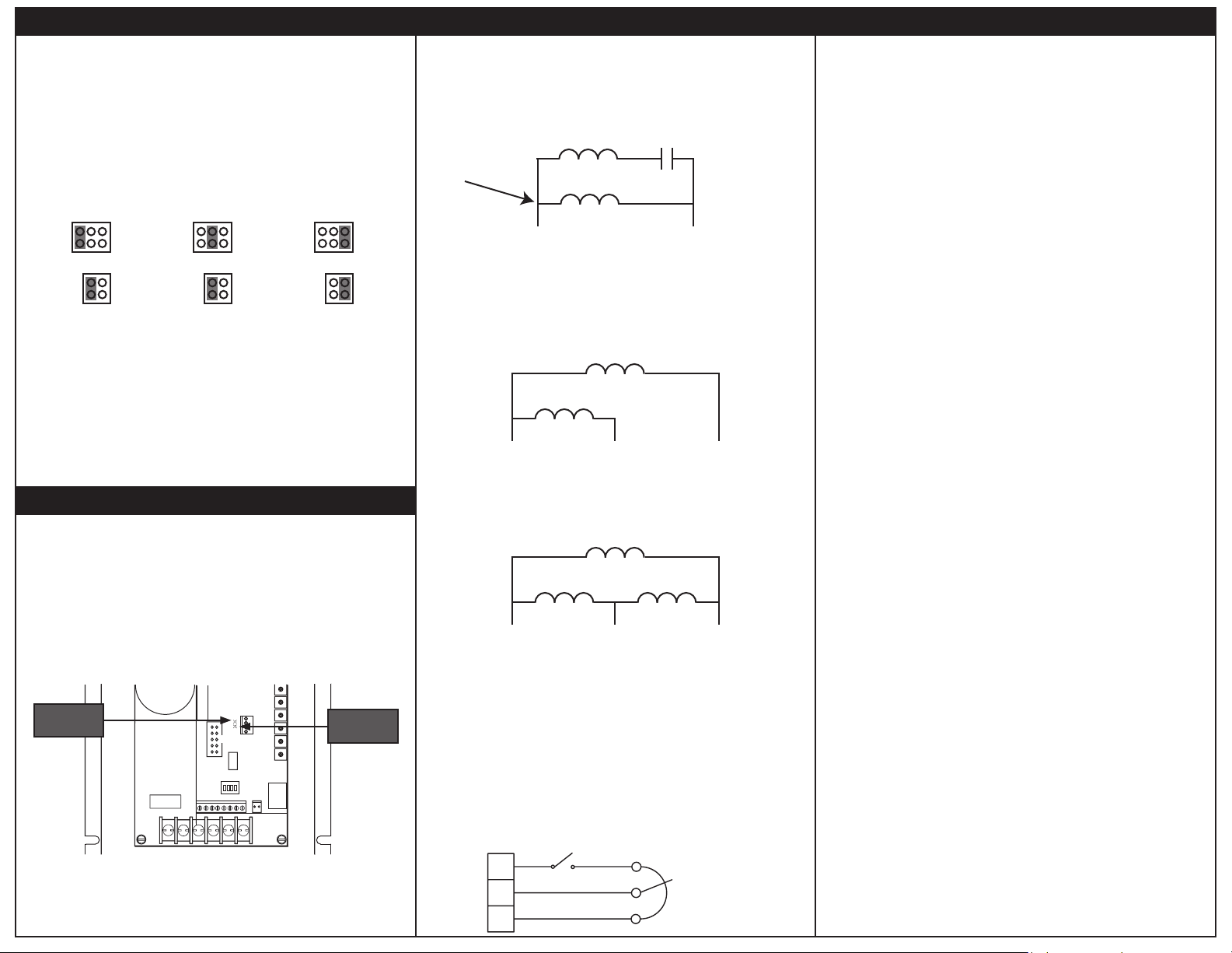
Select Switch (SW501)
Dip Switch 1: ON - 115 VAC Out - Sets a 115 VAC output with 115 or 230 VAC in.
Dip Switch 1:
Dip Switch 2: ON - 50 Hz - Sets a base frequency of 50 Hz on the output.
Dip Switch 2:
Dip Switch 3: ON - Brake Mode - Opening the ENABLE switch will regeneravely brake the motor to
zero speed without applying the decel ramp.
Dip Switch 1:
Dip Switch 4: ON - Carrier frequency of 1.6 kHz (audible, but prevents GFI tripping).
Dip Switch 1:
0-5 VDC or Potenometer 0 to ± 10 VDC 4-20 mA
Jumper Pins 1&2 and 7&8 Jumper Pins 3&5 and 7&8 Jumper Pins 5&6 and 9&10
- Verify that no foreign conducve material is present on the printed circuit board.
- Ensure that all switches and jumpers are properly set.
1. Turn the speed adjust potenometer full counterclockwise (CCW) or set the analog input voltage
1. or current signal to minimum.
2. Apply AC line voltage.
3. Close the enable switch and verify that the green Power LED (IL1) if flashing.
4. Slowly advance the speed adjust potenometer clockwise (CW) or increase the analog input voltage
3. or current signal. The motor slowly accelerates as the potenometer is turned CW or as the analog
3. input voltage or current signal is increased. Connue unl the desired speed is reached.
5. Remove AC line voltage from the drive to coast the motor to a stop.
OFF - 230VAC Out - Sets a 230 VAC output with 115 or 230 VAC in.
OFF - 60 HZ - Sets a base frequency of 60 Hz on the output.
OFF - Enable Mode - Opening the ENABLE switch will coast the motor to a stop.
OFF - Carrier frequency of 16 kHz (not audible, but may cause GFI tripping).
123
5
4
6
7
9
8
10
SELECT SWITCHES
JUMPERS
123
5
4
6
7
9
8
10
STARTUP
123
5
4
6
7
9
8
10
LEDs
Power (IL1): Green LED is solid when AC line voltage is applied to the drive, but the drive is disabled. It
flashes whenever AC line voltage is applied to the drive and the drive is enabled.
Status (IL2): Red LED is solid when in current limit or flashes following fault code:
2 Flashes: Undervoltage - Internal DC BUS voltage dropped below 91 VDC. Will automacally clear
2 Flashes: Undervoltage3 Flashes: Overvoltage - Internal DC BUS voltage rose above 430 VDC. Will automacally clear when
3 Flashes: Overvoltage 4 Flashes: Current Limit or Short Circuit - The drive is in current limit or has detected a short across at
4 Flashes: Current Limit or Short Circuit 5 Flashes: Overtemperature Shut Down - Drive’s temperature has reached crical temperature.
6 Flashes: Overtemperature Warning - Drive’s temperature is approaching crical temperature.
POWER
LED
Copyright 2013 by Minarik Drives - All rights reserved. No part of this document may be reproduced or
retransmied in any form without wrien permission from Minarik Drives. The informaon and
technical data in this document are subject to change without noce. Minarik Drives makes no warranty
of any kind with respect to this material, including, but not limited to, the implied warranes of its
merchantability and fitness for a given purpose. Minarik Drives assumes no responsibility for any errors
that may appear in this document and makes no commitment to update or to keep current the
informaon in this document.
when the DC BUS voltage rises to at least 99.5 VDC.
the DC BUS voltage drops to at least 409 VDC.
least two phases.
IL1
IL2
J502
SW501
J503
TB502
L1 L2/230 L2/115 U V W
205BT
STATUS
LED
Operation
Single Phase Operaon - Non-reversing
For single phase operaon, connect the motor as show in the figure below. Ensure that the prewired
capacitor and its associated motor coil are connected to terminals U and V as shown. This connecon
may be internal if using a 2-wire motor. If the motor has three leads, you must make this connecon
yourself.
This connecon may be
internal to the motor
(2-wire). If not, you must
make this connecon
yourself.
Single Phase Operaon - Reversing
Remove the capacitor and connect the motor as show in the figure below. While allowing for solid-state
reversing, this wiring scheme may result in sub-opmal motor operaon. Depending on the motor
construcon and applicaon requirements, the motor may need to be derated.
U V
Three Phase Operaon
For three phase operaon, connect the motor as show in the figure below. Connect to terminals U, V,
and W as shown.
U V
Decelerate to Minimum or Zero Speed
The switch shown below may be used to decelerate a motor to a minimum speed. Opening the switch
between S3 and the potenometer decelerates the motor from set speed to a minimum speed
determined by the MIN SPEED trim pot seng. If the MIN SPEED trim pot is set full CCW, the motor
decelerates to zero speed when the switch is opened. The DECEL TIME trim pot seng determines the
rate at which the drive decelerates. By closing the switch, the motor accelerates to set speed at a rate
determined by the ACCEL TIME trim pot.
S3
S2
S1
MOTOR CONNECTIONS
AUXILIARY
WINDING
MAIN
WINDING
PREWIRED
RUN CAPACITOR
U V
MAIN
WINDING
AUXILIARY WINDING
WITHOUT CAPACITOR
MOTOR
WINDING
MOTOR
WINDING
DECELERATING & STOPPING
DECEL TO
MIN SPEED
RUN
MOTOR
WINDING
CW
POTENTIOMETER
W
W
10K OHM
SPEED ADJUST
Calibration
Proporonal Gain (P8 / Kp): The constant used to scale the error feedback.
Minimum Speed (P1 / MIN SPEED): The MIN SPEED seng determines the minimum motor speed
when the speed adjust potenometer is set for minimum speed. It is factory set for zero speed. To
calibrate the MIN SPEED:
1. Set the MIN SPEED trim pot full CCW.
2. Set the speed adjust potenometer or input voltage or current signal for minimum speed.
3. Adjust the MIN SPEED trim pot unl the desired minimum speed is reached or is just at the
3. threshold of rotaon.
Maximum Speed (P2 / MAX SPEED): The MAX SPEED seng determines the maximum motor speed
when the speed adjust potenometer or input voltage or current signal is set for maximum speed. It is
factory set for maximum motor rated speed. To calibrate the MAX SPEED:
1. Set the MAX SPEED trim pot full CCW.
2. Set the speed adjust potenometer or input voltage or current signal for maximum forward
speed.
3. Adjust the MAX SPEED trim pot unl the desired maximum forward speed is reached.
Check the MIN SPEED and MAX SPEED adjustments aer recalibrang to verify that the motor runs at
the desired minimum and maximum speeds.
Acceleraon (P3 / ACCEL TIME): The ACCEL TIME seng determines the me the motor takes to ramp
to a higher speed. To calibrate the ACCEL TIME, turn the ACCEL TIME trim pot CW to increase the
acceleraon me.
Deceleraon (P4 / DECEL TIME): The DECEL TIME seng determines the me the motor takes to ramp
to a lower speed. To calibrate the DECEL TIME, turn the DECEL TIME trim pot CW to increase the
deceleraon me.
Slip Compensaon (P5 / SLIP COMP): The SLIP COMP seng determines the degree to which motor
speed is held constant as the motor load changes. To calibrate the SLIP COMP:
1. Set the SLIP COMP trim pot full CCW.
2. Increase the speed adjust potenometer unl the motor runs at midspeed without load. A
2. handheld tachometer may be used to measure motor speed.
3. Load the motor to its full load current rang. The motor should slow down.
4. While keeping the load on the motor, rotate the SLIP COMP trim pot unl the motor runs at
4. the speed measured in step 2. If the motor oscillates (overcompensaon), the SLIP COMP trim
4. pot may be set too high (CW). Turn the SLIP COMP trim pot CCW to stabilize the motor.
5. Unload the motor.
Voltage Boost (P6 / VOLTAGE BOOST): The VOLTAGE BOOST seng increases the motor torque at low
speeds. The minimum seng is sufficient for most applicaons and does not need to be adjusted. If
the motor stalls or runs erracally at very low speeds (below 10 Hz), the boost trim pot may need
adjustment. To calibrate the VOLTAGE BOOST:
1. Run the motor at the lowest connuous speed/frequency required.
2. Increase the VOLTAGE BOOST trim pot unl the motor runs smoothly. Connuous operaon
2. beyond the motor’s current rang may damage the motor.
Torque (P7 / TQ LIMIT): The TQ LIMIT seng determines the maximum torque for accelerang and
driving the motor. To calibrate the TQ LIMIT.
1. With power disconnected from the drive, connect a RMS ammeter in series with one of the
1. motor leads.
2. Turn the TQ LIMIT trim pot to full CW. Apply power and adjust the motor speed to full rated
2. speed.
3. Load the motor so that it draws the RMS current previously determined.
4. Slowly turn the TQ LIMIT trim pot CCW unl the red LED starts flickering. Then turn the trim
4. pot slightly more so that it just starts to reduce the motor amps on the RMS ammeter.
Brake Voltage (P8 / BRAKE VOLTAGE): The brake voltage determines the voltage level at which the
drive will apply current for DC Injecon Braking. The higher the voltage, the more current will be
motor. DC Injecon Braking will only occur in Braking Mode (Dip Switch 3 = ON).
Brake Time-Out (P9 / BRAKE TIME-OUT): The BRAKE TIME-OUT determines how long the DC Injecon
Braking current will be applied when braking. DC Injecon Braking will only occur in Braking Mode (Dip
Switch 3 = ON).
250-0518 rev 0
 Loading...