

Minarik Drives LVBL SERIES Users Manual

LVBL SERIES
USER MANUAL
LVBL02-24AC/DC
www.minarikdrives.com

Dear Valued Consumer:
Congratulaons on your purchase of the LVBL Series drive.
This User Manual was created for you to get the most out of
your new device and assist with the inial setup. Please visit
www.minarikdrives.com to learn more about our other drives.
Thank you for choosing Minarik Drives!
© 2014 Minarik Drives. All rights reserved.
No part of this document may be reproduced or transmied in any form without wrien permission
from Minarik Drives. The informaon and technical data in this document are subject to change
without noce. Minarik Drives makes no warranty of any kind with respect to this material,
including, but not limited to, the implied warranes of its merchantability and tness for a given
purpose. Minarik Drives assumes no responsibility for any errors that may appear in this document
and makes no commitment to update or to keep current the informaon in this document.
Safety First!
SAFETY WARNINGS
Text in gray boxes denote important safety ps or warnings.
Please read these instrucons carefully before performing any of
!
• DO NOT INSTALL, REMOVE, OR REWIRE THIS EQUIPMENT WITH
• Reduce the chance of an electrical fire, shock, or explosion by using
the procedures contained in this manual.
WARNING!
POWER APPLIED. Have a qualified electrical technician install, adjust
and service this equipment. Follow the National Electrical Code
and all other applicable electrical and safety codes, including the
provisions of the Occupational Safety and Health Act (OSHA), when
installing equipment.
proper grounding techniques, over-current protection, thermal
protection, and enclosure. Follow sound maintenance procedures.
It is possible for a drive to run at full speed as a result of a
component failure. Minarik Drives strongly recommends the
!
installaon of a master switch in the main power input to stop
WARNING!
the drive in an emergency.
LVBL Series
i

LVBL Series
Table of Contents
Section 1. Regenerative Drives ............................................ 1
Section 2. Specifications ..................................................... 2
Section 3. Dimensions ......................................................... 3
Section 4. Installation ......................................................... 4
Mounting ..................................................................................... 4
Speed Adjust Potentiometer .................................................. 5
Wiring .......................................................................................... 6
Shielding Guidelines.............................................................. 7
Line Fusing ........................................................................... 7
Connections.................................................................................. 8
Quick Disconnect Terminal Block ........................................... 8
Power Input .......................................................................... 9
Motor ................................................................................... 9
Motor Hall Effect Sensors ...................................................... 9
Speed Adjust Potentiometer .................................................10
Analog Input Signal ..............................................................10
Direction Switch ..................................................................10
Section 5. Operation ......................................................... 12
Before Applying Power .................................................................12
Select Switches ............................................................................13
Hall Effect Sensor Spacing Select (SW501) .............................13
Startup ........................................................................................14
Starting and Stopping Methods ....................................................15
Line Starting and Stopping ...................................................15
Regenerative Brake to Minimum Speed .................................15
Section 6. Calibration ....................................................... 16
Minimum Speed (MIN SPEED) .......................................................17
Maximum Speed (MAX SPEED) ......................................................17
ii

Section 7.Application Notes ............................................... 18
Multiple Fixed Speeds .................................................................. 18
Adjustable Speeds Using Potentiometers In Series .........................19
Independent Adjustable Speeds .................................................... 20
RUN/JOG Switch...........................................................................21
Leader-Follower Application .........................................................22
Single Speed Potentiometer Control Of Multiple Drives .................23
Section 8. Diagnostic LEDs ................................................. 24
Section 9. Troubleshooting ................................................ 25
Before Troubleshooting ................................................................25
Section 10. Accessories & Replacement Parts...................... 28
Unconditional Warranty ..................................................... 29
LVBL Series
iii

LVBL Series
List of Figures
Figure 1 Four Quadrant Operation .................................................. 1
Figure 2 LVBL02-24AC/DC Dimensions ............................................. 3
Figure 3 Speed Adjust Potentiometer .............................................. 5
Figure 4 Quick Disconnect Terminal Block ........................................ 8
Figure 5 LVBL02-24AC/DC Connections ...........................................11
Figure 6 Hall Effect Sensor Spacing Select Location .........................13
Figure 7 Multiple Fixed Speeds ......................................................18
Figure 8 Adjustable Speeds Using Potentiometers in Series .............19
Figure 9 Independent Adjustable Speeds ........................................20
Figure 10 RUN/JOG Switch ................................................................. 21
Figure 11 Leader-Follower Application .............................................22
Figure 12 Single Speed Potentiometer Control of Multiple Drives ......23
Figure 13 Diagnostic LED Locations .................................................. 24
iv
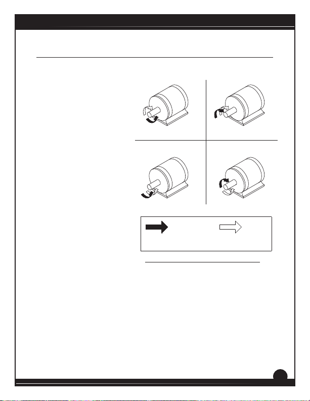
Section 1. Regenerative Drives
Most non-regenerave,
variable speed, DC drives
control current ow to a
motor in one direcon.
The direcon of current
ow is the same direcon
as the motor rotaon.
Non-regenerave drives
operate in Quadrant I,
and also in Quadrant III if
the drive is reversible (see
Figure 1). Motors must stop
before reversing direcon.
Unless dynamic braking
is used, non regenerave
drives cannot decelerate a
load faster than coasng to a
lower speed.
Regenerative drives operate
in two addional quadrants:
Quadrant II and Quadrant
IV. In these quadrants,
motor torque is in the
opposite direcon of motor rotaon.
This allows regenerave drives to reverse a motor without contractors
or switches, to control an overhauling load, and to decelerate a load
faster than it would to coast to a lower speed.
Quadrant II
Quadrant III
MOTOR
ROTATION
NOTE: ARROWS IN SAME DIRECTION = MOTOR ACTION
ARROWS IN OPPOSITE DIRECTION = REGENERATIVE ACTION
Quadrant I
Quadrant IV
Figure 1. Four Quadrant Operaon
LVBL Series
MOTOR
TORQUE
1

LVBL Series
Section 2. Specifications
Connuous
Model
LVBL02-24AC/DC 2 3* 0 - 24 1/100 - 1/44
Armature
Current (ADC)
Peak
Armature
Current (ADC)
Armature
Voltage
Range (VDC) HP Range
* Peak armature current for less than 1 second.
AC Input Voltage 24 - 36 VAC ± 10%, 50/60 Hz, single phase
DC Input Voltage 24 - 48 VDC ± 10%
Armature Voltage Range 0 - 24 VDC
Acceleraon & Deceleraon Time 0.5 seconds
Analog Input Signal Range 0 - 2 VDC (Isolated)
Input Impedance 60K ohms
Form Factor 1.05
Load Regulaon 3% base speed or beer
Speed Range 60:1
Vibraon 0.5G maximum (0 - 50 Hz)
Ambient Temperature Range 0° - 40° C
0.1G maximum (> 50 Hz)
2
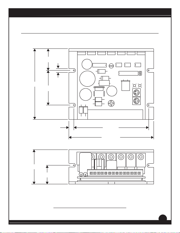
Section 3. Dimensions
LVBL Series
3.58 [91]
1.75 [44]
1.10 [28]
Q502 Q501 Q504 Q503 Q506 Q505
C501
L501
IC504
D501
0.188 [5]
1.75 [44]
C502
IC503
D502
D503
D505
D504
INPUT
DIR S1 S2 S3 HA HB HC COM +5V PH-A PH-B PH-C1 2
0.25 [6] 3.80 [97]
4.30 [109]
0.96 [24]
ALL DIMENSIONS IN INCHES [MILLIMETERS]
Figure 2. LVBL02-24AC/DC Dimensions
IC505 IC506 IC507
IC501
D506
Y501
L502
C503
J501
TRIP POWER
IL502
SW501
120 - 60
IL501
3
LVBL Series
Section 4. Installation
Do not install, rewire, or remove this control with input power
applied. Failure to heed this warning may result in re, explosion,
!
Mounng
• Drive components are sensitive to electrostatic discharge. Avoid
• Protect the drive from dirt, moisture, and accidental contact.
• Provide sufficient room for access to the terminals and calibration
• Mount the drive away from heat sources. Operate the drive within
• Prevent loose connections by avoiding excessive vibration of the
• Mount the drive with its board in either a horizontal or vertical plane.
• The chassis does not need to be earth grounded. If you choose to
or serious injury. Make sure you read and understand the Safety
WARNING!
Precauons on page i before aempng to install this product.
direct contact with the circuit board. Hold the drive by the heat sink
only.
trim pots.
the specified ambient operating temperature range.
drive.
Six 0.19” (5 mm) wide slots in the chassis accept #8 pan head screws.
Fasten either the large base or the narrow flange of the chassis to
the subplate.
ground the chassis, use a star washer beneath the head of at least
one of the mounting screws to penetrate the anodized surface and
to reach bare metal.
4
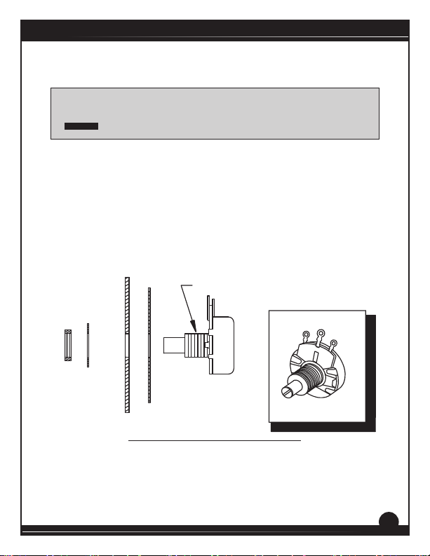
Speed Adjust Potenometer
Be sure that the potenometer tabs do not make contact with the
!
If using a remote potenometer with a chassis drive, mount the speed
adjust potenometer through a 0.38 in. (10 mm) hole with the hardware
provided (Figure 3). Install the circular insulang disk between the panel
and the 10K ohm speed adjust potenometer.
Twist the speed adjust potenometer wire to avoid picking up unwanted
electrical noise. If the speed adjust potenometer wires are longer than
18 in. (46 cm), use shielded cable. Keep the speed adjust potenometer
wires separate from power leads (INPUT 1, INPUT 2, PH A, PH B, PH C).
NUT
potenometer’s body. Grounding the input will cause damage to
WARNING!
the drive.
MOUNT THROUGH A 0.38 IN. (10 MM) HOLE
STAR
WASHER
INSULATING DISK
PANEL
SPEED ADJUST
POTENTIOMETER
CW
POT TAB ASSIGNMENTS
LVBL Series
WIPER
CCW
Figure 3. Speed Adjust Potenometer
5
 Loading...