


GB
D
F
I
E
P
NL
S
FIN
WS 1900
WSA 1900
WSB 1900
WSBA 1900
WSAM 1900
WS 2100
WSA 2100
WSB 2100
WSBA 2100
WS 2300
WSA 2300
WSB 2300
WSBA 2300
Instructions for use
Please read and save these
instructions.
Gebrauchsanleitung
Bitte lesen und aufbewahren.
Instruction d’utilisation
Prière de lire et de conserver.
Istruzioni d’uso
Si prega di leggere le istruzioni e
di conservarle.
Instrucciones de uso
Lea y conserve estas
instrucciones por favor.
Instruções de serviço
Por favor leia e conserve em seu
poder.
Gebruiksaanwijzing
Lees en let goed op deze
adviezen.
Bruksanvisning
Var god läs och tag tillvara dessa
instruktioner.
Käyttöohje
Lue ja säilytö

GB
1 WS/WSB/WSBA 1900/2100/2300
You are a professional, and have decided on
professional quality – from Milwaukee.
Make good use of your new electric power tool, we
have built it to stand up to hard commercial use, but
first read the instruction booklet.
A power tool only performs at its best when
properly handled.
Electric Power Tools from Milwaukee
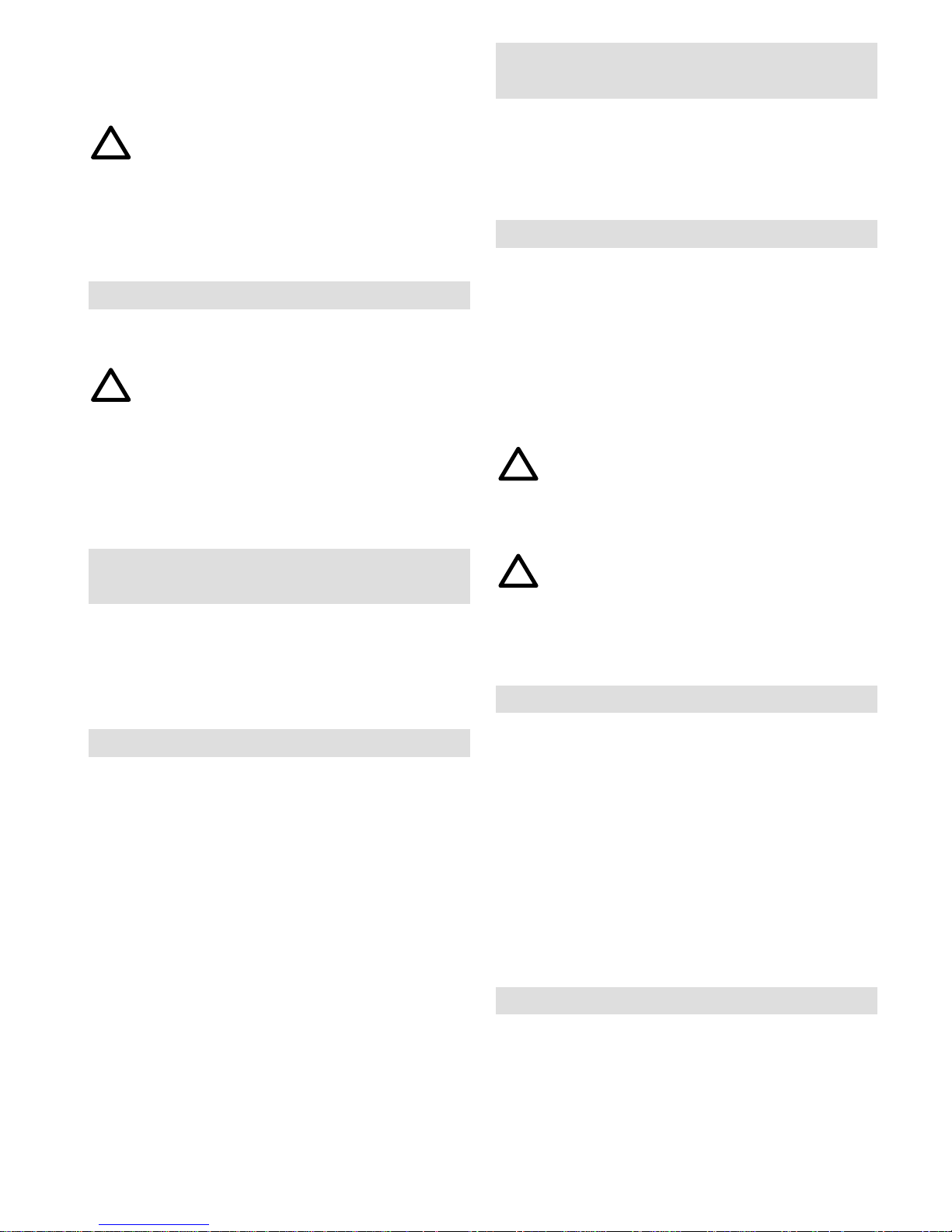
1 Illustration
1 Socket for side handle
2 Spindle lock
3 Gear neck
4 Locating groove
5 Working spindle
6 Locating lug
7 Screw/clamping lever
8 Guard
9 Back flange
10 Grinding disc
11 Flange nut
12 Top of carbon brushes
13 Locking button
14 On-off control
15 Side handle
16 Spade handle (accessory)
17 Screw
18 Backing pad (accessory)
19 Abrasive paper (accessory)
20 Clamping flange
21 Guard plate for adjustment limitation
22 Adjustment limitation for guard plate
23 Steel-wire brush (accessory)
24 Guide shoe and wheel guard (accessory)
2 Technical Data
WS 1900, WSB 1900 WSA 1900, WSBA 1900, WSAM 1900
Power input 1900 W 1900 W. . . . . . . . . . . . . . . . . . . . . . . . . . . . . . . . . . . . . . . . . .
No load speed 8500 min
–1
6600 min
–1
. . . . . . . . . . . . . . . . . . . . . . . . . . . . . . . . . . . .
Grinding disc diameter 180 mm 230 mm. . . . . . . . . . . . . . . . . . . . . . . . . . . . . . . . .
Backing pad diameter 170 mm 220 mm. . . . . . . . . . . . . . . . . . . . . . . . . . . . . . . . . .
Thread of working spindle M 14 M 14. . . . . . . . . . . . . . . . . . . . . . . . . . . . . . .
Weight 4,4 kg 4,4 kg. . . . . . . . . . . . . . . . . . . . . . . . . . . . . . . . . . . . . . . . . . . . . . . . .
WS 2100, WSB 2100 WSA 2100, WSBA 2100
Power input 2100 W 2100W. . . . . . . . . . . . . . . . . . . . . . . . . . . . . . . . . . . . . . . . . .
No load speed 8500 min
–1
6600min
–1
. . . . . . . . . . . . . . . . . . . . . . . . . . . . . . . . . . . .
Grinding disc diameter 180 mm 230mm. . . . . . . . . . . . . . . . . . . . . . . . . . . . . . . . .
Backing pad diameter 170 mm 220mm. . . . . . . . . . . . . . . . . . . . . . . . . . . . . . . . . .
Thread of working spindle M 14 M 14. . . . . . . . . . . . . . . . . . . . . . . . . . . . . . .
Weight 4,6 kg 4,6kg. . . . . . . . . . . . . . . . . . . . . . . . . . . . . . . . . . . . . . . . . . . . . . . . .
WS 2300, WSB 2300 WSA 2300, WSBA 2300
Power input 2300 W 2300W. . . . . . . . . . . . . . . . . . . . . . . . . . . . . . . . . . . . . . . . . .
No load speed 8500 min
–1
6600min
–1
. . . . . . . . . . . . . . . . . . . . . . . . . . . . . . . . . . . .
Grinding disc diameter 180 mm 230mm. . . . . . . . . . . . . . . . . . . . . . . . . . . . . . . . .
Backing pad diameter 170 mm 220mm. . . . . . . . . . . . . . . . . . . . . . . . . . . . . . . . . .
Thread of working spindle M 14 M 14. . . . . . . . . . . . . . . . . . . . . . . . . . . . . . .
Weight 4,8 kg 4,8kg. . . . . . . . . . . . . . . . . . . . . . . . . . . . . . . . . . . . . . . . . . . . . . . . .

!
2WS/WSB/WSBA 1900/2100/2300
3 Safety Instructions
Please pay attention to the safety instructions in
the attached leaflet!
Always disconnect the plug from the mains supply
before carrying out any work on the machine.
Check the plug and mains lead for possible
damage. Damaged or faulty parts should be
repaired by experts only.
Keep mains lead clear from the working range of
the machine.
Only plug in when machine is switched off.
Always use side handle.
Always use guard when grinding or cutting.
Permitted attachments
Type Dia- Speed Peri-
meter pheral
speed
max. max. max.
Synthetic resin
bonded,fibre- 180 mm 8500 min
-1
80 m/sec
reinforced
roughing and
cutting disc
Synthetic resin
bonded, fibre- 230 mm 6600 min
-1
80 m/sec
reinforced
roughing and
cutting disc
Diamond
cutting disc 180 mm 8500 min
-1
80 m/sec
Diamond
cutting disc 230 mm 6600 min
-1
80 m/sec
Rubber backing
pad wit 180 mm 8500 min
-1
80 m/sec
fibre-backed
sanding disc
Rubber backing
pad with
fibre-backed
sanding disc 230 mm 6600 min
–1
80 m/sec
Steel-wire brush 100 mm 8500 min
-1
45 m/sec
Always observe the maximum permissible
peripheral speed/min
-1
specified on the
accessory.
Due care should be taken that sparks flying from
the work piece do not contact inflammable
materials.
Dust from materials containing silica crystals is
injurous to your health.
Mind safety regulations issued by your employer’s
liability insurance association.
Do not use grinder on any material containing
asbestos.
Always wear goggles for all applications. The
wearing of protective gloves and ear defenders is
recommended.
When grinding make sure that the work piece is
firmly supported.
Before setting the machine into motion tighten
flange nut.
In special cases e. g. when the machine is used
under extreme humid conditions or is very
contaminated with conductive dusts, we
recommend the use of an ELCB safety switch
(earth leakage circuit breaker) to increase your
personal safety.
Typically the A-weighted noise levels of the tool
are:
Sound pressure level = 94 dB (A).
Sound power level = 107 dB (A).
Wear ear protectors! Measured values
determined according to EN 50 144.
Typically the weighted acceleration is
6 m/s
2 (
WS..., WSB...)
,
4 m/s2 (WSA..., WSBA..., WSAM...).Measured
values determined according to EN 50 144.
4 Power Supply
Connect only to a single-phase AC current supply
and only to the mains voltage specified on the
rating plate. Connection to sockets without earth
protection is possible as the appliance features
protective insulation to DIN 57 740/ VDE 0740 and
CEE 20. Radio suppression complies with the
European standard EN 55014.
When fitting the plug, make sure that the brown
(live) wire of this appliance is connected to the plug
terminal marked L or coloured red and the blue
(neutral) wire of this appliance is connected to the
plug terminal marked N or coloured black. Under no
circumstances must the wires of this appliance be
connected to the earth terminal of the plug marked
either E, with the earth symbol or coloured green or
green/yellow.
5 Installation of Guard without
Adjustment Limitation
Loosen nut of the clamping lever (7) a little. Push
guard (8) with locating lug (6) onto the locating
groove (4) of the gear neck (3). Then tighten nut
again; only so tight that the clamping lever (7) can
still be clamped over. When the guard is in middle
position it can be adjusted to both sides within a
range of 180
o
.
6 Installation of Guard with Adjustment
Limitation
Loosen nut at the clamping lever (7). Push guard
with locating lugs (6) onto the locating grooves (4)
of the gear neck (3). Place the guard plate for
adjustment limitation (21) onto the screw as
illustrated with the longer part pointing towards the
gear head (3). Tighten nut again, not too tight, so
that the clamping lever (7) can still be clamped
!
!
!
!
3 WS/WSB/WSBA 1900/2100/2300
over.
Through the adjustment limitation the guard is
adjustable to both sides in a range of 60
o
from the
middle position.
Only use the quick adjustment of the guard
when the machine is turned off.
The position of the guard can be adjusted to the
requirements of the work process. When making
this adjustment, take care to ensure that the
grinding disc can rotate freely.
7 Installation of Grinding Disc
Secure working spindle (5) by pressing spindle
lock (2).
Only press spindle lock when the machine is
turned off.
Mount back flange (9), grinding disc (10) and flange
nut (11) according to the illustration and tighten
flange nut with a pin-type spanner.
When the thickness of the disc is less than 5,5 mm
use the flange nut (9) with the flat side against the
grinding disc (10).
8 How dismantle the spade handle
(accessory)
Loosen the screw (17) and pull back the spade
handle (16).
When installing the spade handle (16), push it into
guide and tighten with the screw (17)
9 On-off Control
Intermittant Use
Switching on: Press locking button (13) and then
on-off control (14).
Switching off: Release on-off control (14) and
locking button (13).
Continuous Use
Switching on: Press locking button (13) and then
on-off control (14). Release on-off control (14) and
then release locking button (13).
Switching off: Press on-off control (13) and then
release.
Machines with starting current limit should not be
loaded for 2 seconds after switching on!
Inrush currents cause short–time voltage drops.
Under unfavourable power supply conditions, other
equipment may be affected. If the system
impedance of the power supply is lower than 0,2
Ohm, disturbances are unlikely to occur.
10 Starting Current Limiter (220-240 V)
(only WSB ..., WSBA ...)
The starting current for the machine is several
times greater than rated current.
The starting current limiter produces the starting
current to such an extent that a fuse (16 A,
slow-blow) is not tripped.
11 Hints on Operation
When grinding do not apply pressure to the
workpiece by bearing down on the machine but
move the grinding disc backward and forward over
the working surface.
Grinding
For best results with grinding discs, keep the disc at
an angle at least 30
o
to the working surface.
Overloading the machine during grinding operations
will harm the machine, reduce disc life and produce
inferior results.
Never use cutting discs for grinding
operations.
Cutting
When cutting, avoid tilting the grinder away from
the cutting plane.
When cutting stone, the use of the guide (24)
is necessary.
For grinding larger areas use backing pad with
abrasive paper.
For removal of old paint and for derusting use steel
brush (23).
12 Service
Use only Milwaukee accessories and spare parts.
Should components need to be exchanged which
have not been described, please contact one of our
Milwaukee service agents (see our list of
guarantee/service addresses).
The ventilating slots of the machine must be kept
clear at all times.
If needed, an exploded view of the tool can be
ordered. Please state the ten–digit No. as well as
the machine type printed on the label and order the
drawing at your local service agents or directly at:
Atlas Copco Electric Tools GmbH, Postfach 320,
D–71361 Winnenden.
13 Accessories
The range of accessories with part numbers are
shown in our catalogues.
Modifications: Text, diagrams and data are correct at the time of
printing. In the interest of continuous improvement of our
products, technical specifications are subject to alteration without
prior notice.

D
4WS/WSB/WSBA 1900/2100/2300
Als Profi haben Sie sich für Qualität entschieden –
Qualität von Milwaukee.
Fordern Sie ruhig Ihr neues Elektrowerkzeug, wir
haben es für den harten gewerblichen Einsatz
gebaut, aber lesen Sie vorher die
Gebrauchsanweisung aufmerksam durch, denn
nur in guten Händen schafft ein gutes
Elektrowerkzeug
auch ein gutes Stück Arbeit.
Elektrowerkzeuge von Milwaukee
1 Geräteabbildung
1 Gewinde Zusatzhandgriff
2 Spindelarretierung
3 Spannhals
4 Führungsnuten
5 Arbeitsspindel
6 Führungsstege
7 Schraube/Spannhebel
8 Schutzhaube
9 Spannflansch
10 Arbeitswerkzeug
11 Flanschmutter
12 Deckel Kohlebürsten
13 Einschaltsperre
14 Ein-Ausschalter
15 Zusatzhandgriff
16 Demontierbarer Bügelhandgriff (Zubehör)
17 Befestigungsschraube
18 Schleifteller (Zubehör)
19 Schleifblatt (Zubehör)
20 Spannmutter (Zubehör)
21 Schutzhaubenanschlag
22 Verstellbegrenzung
23 Stahldrahtbürste (Zubehör)
24 Führungsschlitten + Trennschutzhaube (Zub.)
2 Technische Daten
WS 1900, WSB 2100 WSA 1900, WSBA 1900, WSAM 1900
Leistungsaufnahme 1900W 1900 W. . . . . . . . . . . . . . . . . . . . . . . . . . . . . . . . . . . .
Leerlaufdrehzahl 8500min
–1
6600 min
–1
. . . . . . . . . . . . . . . . . . . . . . . . . . . . . . . . . . .
Schleifscheiben-Ø 180mm 230 mm. . . . . . . . . . . . . . . . . . . . . . . . . . . . . . . . . . . . .
Schleifteller-Ø 170mm 220 mm. . . . . . . . . . . . . . . . . . . . . . . . . . . . . . . . . . . . . . . . .
Arbeitsspindelgewinde M 14 M 14. . . . . . . . . . . . . . . . . . . . . . . . . . . . . . . . .
Gewicht 4,4kg 4,4 mm. . . . . . . . . . . . . . . . . . . . . . . . . . . . . . . . . . . . . . . . . . . . . . . . . .
WS 2100, WSB 2100 WSA 2100, WSBA 2100
Leistungsaufnahme 2100W 2100 W. . . . . . . . . . . . . . . . . . . . . . . . . . . . . . . . . . . .
Leerlaufdrehzahl 8500min
–1
6600 min
–1
. . . . . . . . . . . . . . . . . . . . . . . . . . . . . . . . . . .
Schleifscheiben-Ø 180mm 230 mm. . . . . . . . . . . . . . . . . . . . . . . . . . . . . . . . . . . . .
Schleifteller-Ø 170mm 220 mm. . . . . . . . . . . . . . . . . . . . . . . . . . . . . . . . . . . . . . . . .
Arbeitsspindelgewinde M 14 M 14. . . . . . . . . . . . . . . . . . . . . . . . . . . . . . . . .
Gewicht 4,6kg 4,6 mm. . . . . . . . . . . . . . . . . . . . . . . . . . . . . . . . . . . . . . . . . . . . . . . . . .
WS 2300, WSB 2300 WSA 2300, WSBA 2300
Leistungsaufnahme 2300W 2300 W. . . . . . . . . . . . . . . . . . . . . . . . . . . . . . . . . . . .
Leerlaufdrehzahl 8500min
–1
6600 min
–1
. . . . . . . . . . . . . . . . . . . . . . . . . . . . . . . . . . .
Schleifscheiben-Ø 180mm 230 mm. . . . . . . . . . . . . . . . . . . . . . . . . . . . . . . . . . . . .
Schleifteller-Ø 170mm 220 mm. . . . . . . . . . . . . . . . . . . . . . . . . . . . . . . . . . . . . . . . .
Arbeitsspindelgewinde M 14 M 14. . . . . . . . . . . . . . . . . . . . . . . . . . . . . . . . .
Gewicht 4,8kg 4,8 mm. . . . . . . . . . . . . . . . . . . . . . . . . . . . . . . . . . . . . . . . . . . . . . . . . .
!
!
5
WS/WSB/WSBA 1900/2100/2300
3 Sicherheitshinweise
Sicherheitshinweise der beiliegenden Broschüre
beachten!
Vor allen Arbeiten an der Maschine Stecker aus
der Steckdose ziehen.
Stecker und Anschlußkabel auf Beschädigung
kontrollieren. Bei Beschädigung von einem
Fachmann erneuern lassen.
Anschlußkabel stets vom Wirkungsbereich der
Maschine fernhalten.
Maschine nur ausgeschaltet an das Stromnetz
anschließen.
Stets den Zusatzhandgriff verwenden.
Beim Schruppen und Trennen immer mit
Schutzhaube arbeiten.
Zulässige Arbeitswerkzeuge:
Typ Ø Drehzahl Umfangs geschwindig max. max. keit max.
Kunstharzgebundene
faserarmierte
Schrupp–/
Trennscheibe 180 mm 8500 min
–1
80 m/sec
Kunstharzgebundene
faserarmierte
Schrupp–/
Trennscheibe 230 mm 6600 min
–1
80 m/sec
Diamanttrennscheibe 180 mm 8500 min
–1
80 m/sec
Diamanttrennscheibe 230 mm 6600 min
–1
80 m /sec
Gummischleifteller
mit Fiberschleifblatt 180 mm 8500 min
–1
80 m /sec
Gummischleifteller
mit Fiberschleifblatt 230 mm 6600 min
–1
80 m /sec
Gezopfte
Topfbürste 100 mm 8500 min
–1
45 m /sec
Die zulässige
Umfangssgeschwindigkeit/Drehzahl auf dem
Etikett der Arbeitswerkzeuge stets beachten.
Beim Schleifen Funkenflug beachten, da
Brandgefahr bei entzündbaren Materialien
besteht.
Staub, der bei der Bearbeitung von Gestein mit
kristalliner Kieselsäure entsteht, ist
gesundheitsschädlich.
Asbesthaltiges Material darf nicht geschliffen
werden. Entsprechende
Unfallverhütungsvorschrift (VGB 119) der
Berufsgenossenschaft beachten.
Beim Trennen, Schleifen und Bürsten stets
Schutzbrille tragen. Schutzhandschuhe und
Gehörschutz werden empfohlen.
Beim Schleifen auf eine sichere Arbeitsunterlage
achten.
Die Flanschmutter muß vor Inbetriebnahme der
Maschine festgezogen sein.
Bei extremen Einsatzbedingungen (z.B. beim
Glattschleifen von Metallen mit dem Stützteller
und Vulkanfiber-Schleifscheiben) kann sich eine
starke Verschmutzung im Innern des
Winkelschleifers aufbauen. Es empfiehlt sich in
solchen Fällen die Verwendung einer stationären
Absauganlage, eine Verkürzung der
Reinigungszyklen und/oder das Vorschalten eines
Fehlerstrom- (FI) -Schutzschalters.
Der A-bewertete Geräuschpegel des Gerätes
beträgt typischerweise:
Schalldruckpegel = 94 dB (A).
Schalleistungspegel = 107 dB (A).
Gehörschutz tragen!
Meßwerte ermittelt entsprechend EN 50 144.
Die bewertete Beschleunigung beträgt
typischerweise
6 m/s
2
(WS ..., WSB ...),
4 m/s
2
(WSA ..., WSBA ..., WSAM ...).
Meßwerte ermittelt entsprechend EN 50 144.
4 Anschluß
Nur an Einphasen-Wechselstrom und nur an die
auf dem Leistungsschild angegebene
Netzspannung anschließen. Anschluß ist auch an
Steckdosen ohne Schutzkontakt möglich, da eine
Schutzisolierung nach DIN 57 740/ VDE 0740 bzw.
CEE 20 vorliegt. Die Funkentstörung entspricht der
Europanorm EN 55014.
5 Montage der Schutzhaube ohne
Verstellbegrenzung
Mutter am Spannhebel (7) einige Gewindegänge
herausdrehen. Schutzhaube (8) mit
Führungsstegen (6) auf die Führungsnuten (4) im
Spannhals (3) schieben. Die Mutter nur soweit
eindrehen, daß sich der Spannhebel noch umlegen
läßt. Die Schutzhaube ist von der Mittelstellung um
jeweils 180
o
verstellbar.
6 Montage der Schutzhaube mit
Verstellbegrenzung
Mutter am Spannhebel (7) herausdrehen.
Schutzhaube (8) mit Führungsstegen (6) auf die
Führungsnuten (4) im Spannhals (3) schieben.
Schutzhaubenanschlag (21) entsprechend
Abbildung so auf die Schraube (7) legen, daß der
längere Teil auf den Getriebekopf zeigt. Die Mutter
soweit eindrehen, daß sich der Spannhebel noch
umlegen läßt. Durch die Verstellbegrenzung (22) ist
die Schutzhaube von der Mittelstellung um jeweils
60
o
verstellbar.
Die Schutzhaubenverstellung nur im
Stillstand der Maschine betätigen.

!
!
!
6WS/WSB/WSBA 1900/2100/2300
Die Stellung der Schutzhaube kann den
Arbeitserfordernissen angepaßt werden; dabei
darauf achten, daß sich die Schleifscheibe frei
drehen kann.
7 Montage der Arbeitswerkzeuge
Arbeitsspindel (5) durch Drücken auf den
Spindelarretierknopf (2) feststellen.
Spindelarretierknopf nur bei stillstehender
Arbeitsspindel betätigen!
Spannflasch (9), Arbeitswerkzeug (10) und
Flaschmutter (11) entsprechend der Abbildung
montieren und Flanschmutter mit
Zweilochmutterndreher festziehen.
Bei Arbeitswerkzeugen bis ca. 5,5 mm Dicke die
Flaschmutter mit der Planseite zur Arbeitsspindel
verschrauben.
8 Bügelhandgriff demontieren
(Zubehör)
Schraube (17) lösen und Bügel (16) nach hinten
abziehen.
Bei Montage des Bügels (16), diesen in die
Führung einschieben und mit Schraube (17)
befestigen.
9 Zusatzhandgriff
Der Zusatzhandgriff (15) ist in den vorgesehenen
Bohrungen (1) in drei Positionen (links, rechts,
oben) montierbar.
10 Ein-Ausschalten
Momentschaltung
Einschalten: Einschaltsperre (12) und dann
Ein-Ausschalter (14) drücken.
Ausschalten: Ein-Ausschalter (14) und
Einschaltsperre (12) loslassen.
Dauerschaltung
Einschalten: Einschaltsperre (12) und dann
Ein-Ausschalter (14) drücken. Ein-Ausschalter
loslassen und dann Einschaltsperre (gleichzeitig
auch Arretierung) loslassen.
Ausschalten: Ein-Ausschalter (14) drücken und
loslassen.
Maschinen mit Anlaufstrombegrenzung oder
Sanftanlauf erst 2 sec. nach dem Einschalten
belasten.
Einschaltvorgänge erzeugen kurzfristige
Spannungsabsenkungen. Bei ungünstigen
Netzbedingungen können Beeinträchtigungen
anderer Geräte auftreten. Bei Netzimpedanzen
kleiner als 0,2 Ohm sind keine Störungen zu
erwarten.
11 Anlaufstrombegrenzung
WSB ... / WSBA ...
Der Einschaltstrom der Maschine beträgt ein
Mehrfaches des Nennstromes.
Durch die Anlaufstrombegrenzung wird der
Einschaltstrom so weit reduziert, daß eine
Sicherung (16 A träge) nicht anspricht.
12 Arbeitshinweise
Schleifen
Beim Schleifen nicht in das Werkstück
hineindrücken, sondern Schleifscheibe gleichmäßig
über das Werkstück hin- und herbewegen.
Schruppschleifen
Die beste Wirkung beim Schruppschleifen wird
erreicht, wenn die Schleifscheibe in einem Winkel
von mindestens 30
o
zur Schleifebene angesetzt
wird.
Zu starke Belastung während des Schleifens
schadet dem Winkelschleifer und erhöht den
Schleifscheibenverbrauch, die Schleifleistung wird
schlechter.
Niemals Trennscheiben zum
Schruppschleifen verwenden.
Trennschleifen
Bei Trennarbeiten Winkelschleifer in der
Schleifebene nicht verkanten. Die Trennscheibe
muß eine saubere Schnittkante aufweisen.
Bei Montage des Winkelschleifers an Trenn- und
Absaugset darauf achten, daß der Winkelschleifer
parallel zur Tischebene festgespannt wird.
Beim Trennen von Stein ist der
Führungsschlitten (24) Vorschrift!
Zum Flächenschleifen Kunststoffschleifteller mit
Schleifblatt verwenden.
Zum Entfernen alter Farbanstriche oder zum
Entrosten eignet sich eine Stahldrahtbürste (23).
13 Wartung
Nur Milwaukee Zubehör und Ersatzteile
verwenden. Bauteile, deren Austausch nicht
beschrieben wurde, bei einer Milwaukee
Kundendienststelle auswechseln lassen (Broschüre
Garantie/Kundendienstadressen beachten).
Stets die Lüftungsschlitze der Maschine sauber
halten.
Bei Bedarf kann eine Explosionszeichnung des
Gerätes unter Angabe der Maschinen Type und der
zehnstelligen Nummer auf dem Leistungsschild bei
Ihrer Kundendienststelle oder direkt bei Atlas
Copco Electric Tools GmbH, Postfach 320,
D–71361 Winnenden angefordert werden.
14 Zubehör
Das Zubehör mit Bestellnummern ersehen Sie bitte
aus unseren Katalogen.
Änderungen: Text, Bild und Daten entsprechen dem technischen
Stand zur Zeit des Drucktermins. Änderungen im Sinne der
Weiterentwicklung unserer Produkte sind vorbehalten.

F
7 WS/WSB/WSBA 1900/2100/2300
En tant que professionnel, vous avez choisi la
qualité – la qualité Milwaukee.
N’hésitez pas à demander beaucoup de votre
appareil: nous l’avons prévu pour les délicates
applications professionnelles, mais lisez
auparavant avec soin le mode d’emploi, car c’est
seulement lorsqu’il est utilisé par des mains
expertes qu’un outil électrique fait du bon travail.
Outils électriques Milwaukee
1 Illustration
1 Trou taraudé pour poignée
2 Bouton de blocage de l’arbre
3 Collier de serrage
4 Fente de guidage circonférencielle
5 Arbre d’entraînement
6 Bossage circonférenciel
7 Vis de serrage/levier de blocage
8 Carter de protection
9 Flasque de serrage
10 Outil
11 Ecrou de serrage
12 Couvercles d’accès aux balais
13 Verrouillage de mise en marche
14 Interrupteur mache-arrêt
15 Poignée
16 Corps de poignée inférieur démontable (accessoire)
17 Vis de fixation
18 Plateau de ponçage (accessoire)
19 Abrasif (accessoire)
20 Ecrou de serrage (accessoire)
21 Butée du carter de protection
22 Limite de positionnement
23 Brosse métallique (accessoire)
24 Coulisseau de guidage et capot protecteur pour tronçonnage (accessoire)
2 Caractéristiques techniques
WS 1900, WSB 1900 WSA 1900, WSBA 1900, WSAM 1900
Puissance absorbée 1900W 1900 W. . . . . . . . . . . . . . . . . . . . . . . . . . . . . . . . . . .
Vitesse à vide 8500min
–1
6600 min
–1
. . . . . . . . . . . . . . . . . . . . . . . . . . . . . . . . . . . . . .
Ø du disque 180mm 230 mm. . . . . . . . . . . . . . . . . . . . . . . . . . . . . . . . . . . . . . . . . .
Plateau de ponçage Ø 170mm 220 mm. . . . . . . . . . . . . . . . . . . . . . . . . . . . . . . .
Filetage de l’arbre M 14 M 14. . . . . . . . . . . . . . . . . . . . . . . . . . . . . . . . . . . . .
Poids 4,4kg 4,4 kg. . . . . . . . . . . . . . . . . . . . . . . . . . . . . . . . . . . . . . . . . . . . . . . . . . . .
WS 2100, WSB 2100 WSA 2100, WSBA 2100
Puissance absorbée 2100W 2100 W. . . . . . . . . . . . . . . . . . . . . . . . . . . . . . . . . . .
Vitesse à vide 8500min
–1
6600 min
–1
. . . . . . . . . . . . . . . . . . . . . . . . . . . . . . . . . . . . . .
Ø du disque 180mm 230 mm. . . . . . . . . . . . . . . . . . . . . . . . . . . . . . . . . . . . . . . . . .
Plateau de ponçage Ø 170mm 220 mm. . . . . . . . . . . . . . . . . . . . . . . . . . . . . . . .
Filetage de l’arbre M 14 M 14. . . . . . . . . . . . . . . . . . . . . . . . . . . . . . . . . . . . .
Poids 4,6kg 4,6 kg. . . . . . . . . . . . . . . . . . . . . . . . . . . . . . . . . . . . . . . . . . . . . . . . . . . .
WS 2300, WSB 2300 WSA 2300, WSBA 2300
Puissance absorbée 2300W 2300 W. . . . . . . . . . . . . . . . . . . . . . . . . . . . . . . . . . .
Vitesse à vide 8500min
–1
6600 min
–1
. . . . . . . . . . . . . . . . . . . . . . . . . . . . . . . . . . . . . .
Ø du disque 180mm 230 mm. . . . . . . . . . . . . . . . . . . . . . . . . . . . . . . . . . . . . . . . . .
Plateau de ponçage Ø 170mm 220 mm. . . . . . . . . . . . . . . . . . . . . . . . . . . . . . . .
Filetage de l’arbre M 14 M 14. . . . . . . . . . . . . . . . . . . . . . . . . . . . . . . . . . . . .
Poids 4,8kg 4,8 kg. . . . . . . . . . . . . . . . . . . . . . . . . . . . . . . . . . . . . . . . . . . . . . . . . . . .

!
8
WS/WSB/WSBA 1900/2100/2300
3 Instructions de sécurité
Respecter les instructions de sécurité se trouvant
dans le prospectus ci-joint.
Avant tous travaux sur la machine la débrancher.
Maintenir le câble toujours le plus éloigné
possible du poste de travail.
Avant de raccorder la machine au réseau
électrique, s’assurer que le câble et la prise soient
en bon état. En cas de dommages, faire procéder
à leur remplacement par un spécialiste.
Maintenir le câble toujours en dehors de l’aire de
travail de la machine.
Ne raccorder la machine au réseau que si
l’interrupteur est en position arrêt.
Utiliser toujours la poignée latérale.
Pour les travaux de dégrossissage et de
tronçonnage utiliser toujours le capot protecteur.
Outils de travail compatibles
Type Ø Régime Vitesse
péri-
maxi maxi phérique
maxi
Meule à dégrossir/
à tronçonner en
résine synthétique 180 mm 8500 min
–1
80m/sec
armée de fibres
Meule à dégrossir/
à tronçonner en
résine synthétique 230 mm 6600 min
–1
80 m/sec
armée de fibres
Meule à
tronçonnage 180 mm 8500 min
–1
80 m/sec
au diamant
Meule à
tronçonnage 230 mm 6600 min
–1
80 m/sec
au diamant
Plateau en
caoutchouc avec 180 mm 8500 min
–1
80 m/sec
abrasif
Plateau en
caoutchouc 230 mm 6600 min
–1
80 m/sec
avec abrasif
Brosse
cylindrique 100 mm 8500 min
–1
45 m/sec
tressée
Respecter systématiquement la vitesse
périphérique maximale ou le régime maximal
admissible figurant sur l’étiquette.
Pendant les travaux de meulage veiller aux
étincelles car danger d’incendie des matières
inflammables.
Les poussières issues des travaux de meulage
sur des pierres contenant de l’acide silicilique
cristallin sont nocives.
Ne jamais meuler des matériaux contenant de
l’amiante. Respecter les consignes de sécurité du
syndicat professionnel.
Porter toujours des lunettes de protection pendant
les travaux de meulage et de brossage. Le port
de gants de protection et de protection
accoustique est conseillé.
Veiller à utiliser un support de travail solide pour
les opérations de meulage.
L’écrou de serrage doit être bien serré avant la
mise en marche de la machine.
Pour une meilleure securité il est recommandé
d’utiliser un disjoncteur de protection (30 mA) par
ex: lors de grande humidité ou d’un encrassement
de l’outil par des poussières électro-statiques.
Les mesures réelles (A) des niveaux de bruit de la
machine sont:
Intensité de bruit =94 dB (A).
Niveau de bruit = 107 dB (A).
Munissez-vous de casques protecteurs sur les
oreilles!Valeurs de mesure obtenues
conformément à la norme européenne 50 144.
L’accélération réelle mesurée est
6 m/s
2
(WS ..., WSB ...),
4 m/s
2
(WSA ..., WSBA ..., WSAM ...).
Valeurs de mesure obtenues conformément à la
norme européenne 50 144.
4 Raccordement
Nos machines fonctionnent sur courant alternatif
monophasé. S’assurer que la tension du réseau
correspond à celle indiquée sur la plaque
signalétique de la machine. Le branchement à une
prise de courant sans mise à la terre est possible
du fait de la double isolation suivant normes DIN 57
740/VDE 0740 et CEE 20. Antiparasitage suivant la
norme européenne EN 55014.
5 Montage du carter de protection à
positionnement illimité
Desserrer légèrement l’écrou du levier de
verrouillage. Monter le carter de protection avec
bessage circonférenciel dans la fente du collier de
la machine. Resserrer l’écrou de façon que le levier
de verrouillage se laisse encore manœuvrer. Le
carter de protection est réglable sur 180
o
.

!
!
!
!
9 WS/WSB/WSBA 1900/2100/2300
6 Montage du carter de protection à
positionnement limité
Desserrer l’écrou du levier de verrouillage (7).
Monter le carter de protection (8) avec le bossage
circonférenciel (6) dans la fente du collier de la
machine.
Placer la butée du carter de protection (21) suivant
photo sur la vis de façon que la partie longue
montre en direction de la tête d’engrenage (3).
Resserrer l’écrou de façon que le levier de serrage
(7) se laisse manœuvrer. Du fait de la limitation du
positionnement le carter est réglable de 60
o
dans
chaque direction.
Ne manœuvrer le levier de blocage du carter
de protection et celui-ci que la machine à
l’arrêt.
La position du capot protecteur peut être adaptée
aux besoins de l’opération; il faut veiller à ce que le
disque de meulage tourne librement.
7 Montage des outils de travail
Fixer la broche (5) en appuyant sur le bouton de
blocage de la broche (2).
N’actionner le bouton de la broche que
lorsque la broche est arrêtée.
Monter le flasque de serrage (9), l’outil de travail
(10) et l’écrou de serrage (11) selon l’illustration et
serrer l’écrou de serrage avec la clé à ergots. Pour
les outils de travail d’une épaisseur supérieure à
5,5 mm, visser l’écrou de serrage, le côté plat
faisant face à la broche.
8 Démontage du corps de poignée
inférieure
(accessoire)
Dévisser la vis (17) et tirer le corps (16) vers
l’arriere.
Pour le remontage du corps (16) glisser celni–ci
dans l’évidemment et lefixer en serrant la vis (17).
9 Mise en marche/arrêt
Mise en marche: Appuyer sur le verrouillage de
mise en marche (13) et ensuite sur l’interrupteur (14).
Arrêt: Relâcher interrupteur (14) et verrouillage de
mise en marche (13).
Ne travailler en charge avec les machines à limiteur
d’intensité ou à démarrage progressif qu’environ
deux secondes après la mise en marche.
Les processus de mise en fonctionnement
provoquent des baisses momentanées de tension.
En cas de conditions défavorables de secteur, il
peut y avoir des répercussions sur d
appareils. Pour des impédances du secteur
inférieures à 0,2 ohms, il est assez improbable que
des perturbations se produisent.
10 Limitation du courant de démarrage
(WSB ..., WSBA ...)
La tension d’amorcage de la machine est un
multiple de sa tension nominale.
Grâce à la limitation du courant de démarrage, la
tension d’amorcage est réduite à tel point qu’un
fusible (16 A à action retardée) ne répond pas.
11 Instructions d’utilisation
Meulage
Pendant le meulage, ne pas appuyer l’outil dans le
matériau mais lui faire faire un mouvement de va et
vient au-dessus du matériau.
Dégrossissage
En travaux de dégrossissage les meilleurs résultats
sont obtenus lorsque la meule est placée à un
angle de 30
o
contre la surface du matériau.
Une pression trop forte exercée sur la meuleuse
pendant les opérations diminue la longévité de la
meule et de la machine et donne de mauvais
résultats.
Ne jamais utiliser de meules de tronçonnage
pour dégrossir.
Tronçonnage
Pour les opérations de tronçonnage, ne pas coincer
la meuleuse dans le plan de meulage. La meule
doit avoir un tranchant bien profilé et propre.
Utiliser obligatoirement le rail de guidage (24)
en tronçonnant de la roche.
Pour le meulage de surfaces, utiliser le plateau de
meulage en plastique avec disque.
Pour décaper des vieilles peintures ou de la rouille,
utiliser la brosse métallique (23).
12 Entretien
N’utiliser que des pièces et accessoires Milwaukee.
Pour des pièces dont l’échange n’est pas décrit,
s’adresser de préférence aux stations de service
après-vente Milwaukee (voir brochure
Garantie/Adresses des stations de service
après-vente).
Tenir toujours propre les orifices de ventilation de la
partie moteur.
Si besoin est, une vue éclatée de l’appareil peut
être fournie. S’adresser, en indiquant bien le
numéro à dix chiffres porté sur la plaque
signalétique, à votre station de service après–vente
(voir liste jointe) ou directement à Atlas Copco
Electric Tools GmbH, B.P. 320, D–71361
Winnenden.
13 Accessoires
Consulter notre catalogues qui vous renseignent
sur notre programme d’accessoires avec leur
référence.
Modifications: Les textes, les illustrations et les données
techniques correspondent à la situation au moment de
l’impression. Toutes modifications techniques sont réservées
dans le cadre du développement technique permanent.

I
10
WS/WSB/WSBA 1900/2100/2300
Le i chiede molto ad un prodotto, per questo motivo
ha scelto la sicurezza della qualità: la qualità
Milwaukee
Abbiamo costruito questo elettroutensile con molta
cura, perciò, lo usi in tutta tranquilità; le chiediamo
solo di leggere prima queste istruzioni per l’uso,
perché è solo in buone mani che un buon
elettroutensile puó fare un buon lavoro.
Elettroutensile della Milwaukee
1 Foto dell’utensile
1 Filettatura per impugnatuta laterale
2 Blocco albero portautensili
3 Collare
4 Fessure di guida
5 Albero portautensili
6 Fessure di guida
7 Vite/Leva di bloccaggio
8 Calotta di protezione
9 Flangia di bloccaggio
10 Utensile di lavoro
11 Dado di bloccaggio
12 Coperchio spazzole di carbone
13 Blocco avviamento
14 Interruttore
15 Impugnatura laterale
16 Impugnatura a staffa smontabile (accessorio)
17 Vite di fissaggio
18 Platorello (accessorio)
19 Carta smeriglio (accessorio)
20 Dado di bloccaggio (accessorio)
21 Riscontro calotta di protezione
22 Limitazione di regolazione
23 Spazzola in filo d’acciaio (accessorio)
24 Slitta di guida e calotta di protezione per troncare (accessorio)
2 Dati tecnici
WS 1900, WSB 1900 WSA 1900, WSBA 1900, WSAM 1900
Potenza assorbita 1900 W 1900 W. . . . . . . . . . . . . . . . . . . . . . . . . . . . . . .
Velocità a vuoto 8500 min
–1
6600 min
–1
. . . . . . . . . . . . . . . . . . . . . . . . . . . . . .
Ø max. mole smeriglio 180 mm 230 mm. . . . . . . . . . . . . . . . . . . . . . . . . . . . .
Ø max. platorello 170 mm 220 mm. . . . . . . . . . . . . . . . . . . . . . . . . . . . . . . . . .
Filetto albero portautensili M 14 M14. . . . . . . . . . . . . . . . . . . . . . . . . . .
Peso 4,4 kg 4,4 kg. . . . . . . . . . . . . . . . . . . . . . . . . . . . . . . . . . . . . . . . . . . . . .
WS 2100, WSB 2100 WSA 2100, WSBA 2100
Potenza assorbita 2100 W 2100 W. . . . . . . . . . . . . . . . . . . . . . . . . . . . . . .
Velocità a vuoto 8500 min
–1
6600 min
–1
. . . . . . . . . . . . . . . . . . . . . . . . . . . . . .
Ø max. mole smeriglio 180 mm 230 mm. . . . . . . . . . . . . . . . . . . . . . . . . . . . .
Ø max. platorello 170 mm 220 mm. . . . . . . . . . . . . . . . . . . . . . . . . . . . . . . . . .
Filetto albero portautensili M 14 M14. . . . . . . . . . . . . . . . . . . . . . . . . . .
Peso 4,6 kg 4,6 kg. . . . . . . . . . . . . . . . . . . . . . . . . . . . . . . . . . . . . . . . . . . . . .
WS 2300, WSB 2300 WSA 2300, WSBA 2300
Potenza assorbita 2300 W 2300 W. . . . . . . . . . . . . . . . . . . . . . . . . . . . . . .
Velocità a vuoto 8500 min
–1
6600 min
–1
. . . . . . . . . . . . . . . . . . . . . . . . . . . . . .
Ø max. mole smeriglio 180 mm 230 mm. . . . . . . . . . . . . . . . . . . . . . . . . . . . .
Ø max. platorello 170 mm 220 mm. . . . . . . . . . . . . . . . . . . . . . . . . . . . . . . . . .
Filetto albero portautensili M 14 M14. . . . . . . . . . . . . . . . . . . . . . . . . . .
Peso 4,8 kg 4,8 kg. . . . . . . . . . . . . . . . . . . . . . . . . . . . . . . . . . . . . . . . . . . . . .

!
11 WS/WSB/WSBA 1900/2100/2300
3 Norme di sicurezza
Si prega di leggere con attenzione le istruzioni
riguardanti la sicurezza, nel volantino allegato.
Prima di qualsiasi intervento sull’apparecchio,
estrarre sempre la spina dalla presa di corrente.
Controllare sempre lo stato della spina e del cavo
di collegamento. In caso risultassero danneggiati,
farli ripristinare da un tecnico specializzato.
Tenere sempre lontano il cavo di collegamento
dall’area di lavoro dell’attrezzo.
Inserire la spina solo con interruttore su posizione
OFF.
Utilizzare sempre l’impugnatura laterale.
Nella sgrossatura e nella troncatura lavorare
sempre con la calotta di protezione.
Utensili di lavoro ammessi
Tipo Dia- Velocità Velocità
metro periferica
max. max. max.
Mola smeriglio/
da troncare
legata in resina
artificiale con
armartura in fibra 180 mm 8500 min
–1
80 m/sec
Mola smeriglio/
da troncare
legata in resina
artificale con
armatura in fibra 230 mm 6600 min
–1
80 m/sec
Mola per
troncare
diamantata 180 mm 8500 min–
1
80 m/sec
Mola per
troncare
diamatata 180 mm 8500 min
–1
80 m/sec
Mola per
troncare
diamantata 230 mm 6600 min
–1
80 m/sec
Platorello in
gomma con
disco smeriglio
in fibra 180 mm 8500 min
–1
80 m/sec
Platorello in
gomma con
disco smeriglio
in fibra 230 mm 6600 min
–1
80 m/sec
Spazzola a
tazza con filo
intrecciato 100 mm 8500 min
–1
45 m/sec
Osservare sempre l’ammessa velocità
periferica e quella circolare riportata
sull’etichetta degli utensili di lavoro.
Nella smerigliatura osservare sempre la traiettoria
delle scintille causa pericolo di incendio di
materiali infiammabili.
La polvere formatasi nella lavorazione della pietra
contenente acido silicico cristallino é dannosa alla
salute.
Materiali contenenti amianto non devono essere
smerigliati. Osservare le relative prescrizioni
antiifortunistiche (VGB 119) del Consorzio
professionale.
Nei lavori di troncatura, smerigliatura e
spazzolatura usare sempre occhiali di protezione.
Viene raccomandato l’uso di guanti di protezione
e cuffie antirumore.
Nel lavoro di smerigliatura prevedere un appoggio
sicuro del maufatto.
Il dado di bloccaggio utensili, prima della messa in
servizio della macchina, deve essere bloccato.
Per una maggiore sicurezza personale in casi
speciali può essere raccomandabile impiegare un
interruttore di sicurezza contro le correnti vaganti
(30 mA), per es. in presenza di elevata umidità o
rilevante sporcizia dell’apparecchio tramite
polvere conducente.
La misurazione A del livello di rumorosità di un
utensile è di solito:
Livello di rumorosità = 94 dB (A).
Potenza della rumorosità = 107 dB (A).
Utilizzare le protezioni per l’udito! Valori misurati
conformemente alla norma EN 50 144.
La misurazione dell’accellerazione di solito è
6 m/s
2
(WS ..., WSB ...),
4 m/s
2
(WSA ..., WSBA ..., WSAM ...). Valori
misurati conformemente alla norma EN 50 144.
4 Collegamento
Alimentazione dell’utensile: corrente alternata
monofase. Importante: La tensione di rete deve
corrispondere a quella riportata sulla targhetta
dell’utensile. Il collegamento è possibile anche con
prese non munite di contatto di protezione: è
previsto infatti un isolamento di protezione
conforme a DIN 57 740/VDE 0740 (CEE 20). La
schermatura contro i radio-disturbi è conforme a
EN 55014.
5 Montaggio della calotta di protezione
senza limitazione di regolazione.
Svitare di qualche giro il dado di bloccaggio (7).
Inserire i binari di guida (6) della calotta di protezione (8) nelle fessure di guida (4) nel collare (3).
Avvitare il dado tanto che la leva di bloccaggio sia
ancora mobile. La calotta di protezione, partendo
dalla sua posizione centrale, é regolabile di 180
o
nelle due direzioni.
6 Montaggio della calotta di protezione
con limitazione di regolazione
Evitare il dado della leva di bloccaggio (7). Inserire
il banario di guida (6) della calotta di protezione (8)

!
!
!
!
12
WS/WSB/WSBA 1900/2100/2300
nelle fessure di guida (4) nel collare (3). Porre il
riscontro della calotta di protezione (21), come da
illustrazione, sulla vite (7) in modo che la parte più
lunga sia rivolta verso la testata della macchina.
Avviate il dado tanto che la leva di bloccaggio sia
ancora mobile. Tramite la limitazione di regolazione (22) la calotta di protezione, partendo dalla
sua posizione centrale, é regolabile di 60
o
nelle due
direzioni.
azionare la regolazione della calotta di
protezione solo a macchina ferma.
La posizione della calotta si può adattare alle
necessità della lavorazione, facendo attenzione che
la mola possa ruotare liberamente.
7 Montaggio degli utensili di lavoro
Bloccare l’albero portautensili (5) tramite pressione
sul bottone blocco albero portautensili (2).
azionare il bottone blocco albero portautensili
solo ad albero fermo!
Montare, secondo l’illustrazione, la flangia di
bloccaggio (9), l’utensile di lavoro (10) ed il dado di
bloccaggio (11) e bloccare quest’ultimo poi con la
chiave a forcella. Con utensili di lavoro con
spessore fino a 5,5 mm ca. montare il dado di
bloccaggio con la parte piana rivolta verso l’albero
portautensili.
8 Impugnatura a staffa smontabile
(accessorio)
svitare (17) e togliere indietro la staffa (16).
Per il montaggio inserire la staffa nell’apposita
guida e fissarla con la vite
9 Accensione-Spegnimento
Avviamento istantaneo
Avviamento: premere il blocco avviamento (13) e
poi l’interruttore (14).
Disinserimento:: lasciare libero l’interruttore (14) e il
blocco avviamento (14).
Funzionamento continuo
Avviamento: premere il blocco avviamento (13) e
poi l’interruttore (14).
Disinserimento: premere l’interruttore (14) e
lasciare libero.
Gli apparecchi con limitatore di corrente allo spunto
o avviamento morbido possono essere sottoposti a
carico solo 2 sec. dopo la loro attivazione
10 Limitazione della corrente
d’avviamento WSB ..., WSBA ...
La corrente d’avviamento della macchina ha un
valore multiplo della corrente nominale.
Mediante la limitazione della corrente d’avviamento,
essa viene ridotta in modo da non causare lo
sgancio dell’interruttore automatico (da 16 A).
11 Avvertenze operative
Smerigliare
Nella smerigliatura non premere la mola contro il
manufatto, bensí farla passare in modo uniforme
avanti ed indietro sul manufatto.
Smerigliatura di sgrosso
Il miglior rendimento nella smerigliatura di sgrosso
si ottiene tenendo la mola inclinata con un angolo di
almeno 30
o
rispetto al piano.
Un carico eccessivo durante la smerigliatura
danneggia la smerigliatrice e fa aumentare l’usura
della mola; il rendimento peggiora.
Per la smerigliatura di sgrosso non usare mai
mole di troncatura.
Troncatura
Nei lavori di troncatura non far inceppare la
smerigliatrice nel piano di smerigliatura. Il disco
deve presentare un bordo di troncatura in perfetto
stato.
Per la troncatura di pietre è prescritto l’uso
della slitta di guida (24).
Per asportare vecchie vernici o ruggine si deve
usare una spazzola in filo di ferro.
12 Manutenzione
Utilizzare esclusivamente accessori e pezzi di
ricambio Milwaukee. L’installazione di pezzi di
ricambio non specificamente prescritti
dall’Milwaukee va preferibilmente effettuata dal
servizio di assistenza clienti Milwaukee (ved.
opuscolo Garanzia/Indirizzi Assistenza tecnica).
Tenere pulite accuratamente le fessure di aerazione
sulla carcassa del motore.
In caso di mancanza del disegno esploso, può
essere richiesto al seguente indirizzo:
Atlas Copco Tools
Divisione Tools
Via Fratelli Gracchi 39
20092 Cinisello Balsamo Mi
13 Accessori
Per la vasta gamma di accessori e relativi codici
consultare i nostri cataloghi.
Modifiche: Testo, figure e dati corrispondono allo standard
tecnico aggiornato all’epoca della stampa. Ci riserviamo pertanto
eventuali modifiche tecniche dovute all’ulteriore sviluppo dei
nostri prodotti.

E
13
WS/WSB/WSBA 1900/2100/2300
Usted exige lo mejor y compra calidad – la calidad
que ofrece Milwaukee. Hemos fabricado para usted
una herramienta fiable y duradera. Sólo es posible
trabajar de forma eficaz y sin riesgo para su salud
si lee atentamente estas instrucciones antes de
usar la herramienta. Queremos satisfacer a
nuestros clientes y nos gustaría que Vd. volviera a
comprar una
Herramienta Eléctrica de Milwaukee.
1 Representación del aparato
1 Rosca del asidero adicional
2 Bloqueo del husillo
3 Cuello de apriete
4 Llave de codificación
5 Husillo de trabajo
6 Codificación
7 Tornillo/Palanca tensora
8 Cobertura de protección
9 Brida tensora
10 Herramienta de trabajo
11 Tuerca brida
12 Tope escobillas
13 Bloqueo de conexión
14 Interruptor de co/desconexión
15 Asidero adicional
18 Plato de esmerilar (accesorio)
19 Hoja de esmerilar (accesorio)
20 Tuerca de apriete (accesorio)
21 Tope de cobertura de protección
22 Limitación de desplazamiento
23 Cepillo de cerdas de acero (accessorio)
24 Carrillo guía y cobertura de protección de
de tronzar (accessorio)
2 Datos técnicos
WS 1900, WSB 1900 WSA 1900, WSBA 1900, WSAM 1900
Potencia absorvida 1900 W 1900 W. . . . . . . . . . . . . . . . . . . . . . . . . . . . . . . . . . . . . . . .
Velocidad en bacío 8500 min
–1
6600 min
–1
. . . . . . . . . . . . . . . . . . . . . . . . . . . . . . . . . . . . .
Ø Diámetro del disco de esmerilar en 180 mm 230 mm. . . . . . . . . . . . . . . . . . . . . . . . .
Ø Plato de desbastar en 170 mm 220 mm. . . . . . . . . . . . . . . . . . . . . . . . . . . . . . . . . . . . .
Rosca del husillo de trabajo M 14 M 14. . . . . . . . . . . . . . . . . . . . . . . . . . . . . . . . . . .
Peso en 4,4 kg 4,4 kg. . . . . . . . . . . . . . . . . . . . . . . . . . . . . . . . . . . . . . . . . . . . . . . . . . . . .
WS 2100, WSB 2100 WSA 2100, WSBA 2100
Potencia absorvida 2100 W 2100 W. . . . . . . . . . . . . . . . . . . . . . . . . . . . . . . . . . . . . . . .
Velocidad en bacío 8500 min
–1
6600 min
–1
. . . . . . . . . . . . . . . . . . . . . . . . . . . . . . . . . . . . .
Ø Diámetro del disco de esmerilar en 180 mm 230 mm. . . . . . . . . . . . . . . . . . . . . . . . .
Ø Plato de desbastar en 170 mm 220 mm. . . . . . . . . . . . . . . . . . . . . . . . . . . . . . . . . . . . .
Rosca del husillo de trabajo M 14 M 14. . . . . . . . . . . . . . . . . . . . . . . . . . . . . . . . . . .
Peso en 4,6 kg 4,6 kg. . . . . . . . . . . . . . . . . . . . . . . . . . . . . . . . . . . . . . . . . . . . . . . . . . . . .
WS 2300, WSB 2300 WSA 2300, WSBA 2300
Potencia absorvida 2300 W 2300 W. . . . . . . . . . . . . . . . . . . . . . . . . . . . . . . . . . . . . . . .
Velocidad en bacío 8500 min
–1
6600 min
–1
. . . . . . . . . . . . . . . . . . . . . . . . . . . . . . . . . . . . .
Ø Diámetro del disco de esmerilar en 180 mm 230 mm. . . . . . . . . . . . . . . . . . . . . . . . .
Ø Plato de desbastar en 170 mm 220 mm. . . . . . . . . . . . . . . . . . . . . . . . . . . . . . . . . . . . .
Rosca del husillo de trabajo M 14 M 14. . . . . . . . . . . . . . . . . . . . . . . . . . . . . . . . . . .
Peso en 4,8 kg 4,8 kg. . . . . . . . . . . . . . . . . . . . . . . . . . . . . . . . . . . . . . . . . . . . . . . . . . . . .

!
14
WS/WSB/WSBA 1900/2100/2300
3 Instrucciones de seguridad
Preste atención a las instrucciones de seguridad
del libro adjunto.
Antes de realizar cualquier trabajo en la máquina,
sacar la clavija de la base de enchufe.
Controlar en cuanto a deterioros posibles el cable
de alimentación, si existieran deterioros mandar
cambiar el cable a un especialista.
Mantener siempre el cable separado del radio de
acción de la máquina.
Enchufar la máquina a la red solamente en
posición desconectada.
Emplear siempre el asidero adicional.
Para tronzar o debastar, emplear siempre la
cobertura de protección.
Herramientas de trabajo admisibles
Avance DiámetroVelocidad
(máx.) (màx.) (máx.)
Aglomerado de
resina sintética
(armado de
fibra sintética) 80 m/sec 180 mm 8500 r.p.m.
disco de
tronzar/esmerilar
Aglomerado de
resina sintética
(armado de
fibra sintética) 80 m/sec 230 mm 6600 r.p.m.
disco de
esmerilar/tronzar
Disco de tronzar
de diamante 80 m/sec 180 mm 8500 r.p.m.
Disco de tronzar
de diamante 80 m/sec 230 mm 6600 r.p.m.
Plato de goma
con hoja de fibra 80 m/sec 180 mm 8500 r.p.m.
Plato de goma
con hoja de fibra 80 m/sec 230 mm 6600 r.p.m.
Cepillo de copa
trenzado 45 m/sec 100 mm 8500 r.p.m.
Observe las velocidades de giro avance
reflejados en la etiqueta de características
de la herramienta de trabajo.
Al esmerilar, tener cuidado con la cola de
chispas, pues existe peligro de incendio con
materiales inflamables.
El polvo que se produce al trabajar en piedras
con contenido de ácido silicico cristalino, es
perjudicial para la salud.
Materiales con contenido de amianto, no se
deben esmerilar. Observar las normas que sobre
seguridad y salubridad dicte el comité
correspondiente.
Al tronzar, esmerilar o cepillar, emplear siempre
las gafas de protección, se recomienda
adicionalmente el empleo de guantes y
protectores auditivos.
Al esmerilar, emplear un soporte de trabajo
seguro.
Antes de poner la maquiná en marcha tiene que
estar bien apretada la tuerca brida.
Para mejorar la seguridad del usuario, será
indicado utilizar en algunas ocasiones especiales
un protector magnético (30 mA), p. ej.:
sobrecarga por humedad o gran acumulación de
suciedad por particulas conductoras del aparato.
El nivel de ruido de la máquina se eleva
normalmente:
Presión acústica = 94 dB (A).
Resonancia acústica = 107 dB (A).
Usar protectores auditivos!
La acelaración se eleva normalmente a
6 m/s
2
(WS ..., WSB ...),
4 m/s
2
(WSA ..., WSBA ..., WSAM ...).
4 Alimentación/Conexión
Conectar solamente a corriente alterna monofásica
y solo a la tensión indicada en la placa de
características. También se puede conectar a una
base de enchufe sin contacto de protección, ya que
el aparato posee un aislamiento según norma DIN
57 740/VDE 0740 correspondientes a CEE 20.
La protección antiparasitaria corresponde a la
norma europea EN 55014.
5 Montaje de la cobertura de protección
sin limitación de desplazamiento
Aflojar un par de hilos la tuerca de la palanca
tensora (7) introducir la cobertura de protección (8)
con los nervios de posición (6) en la leva
direccional (4) del cuello de apriete (3). Apretar la
tuerca hasta que la palanca de apriete se pueda
voltear. La cobertura de protección se puede
desplazar desde la posición media 180
o
en cada
sentido.
6 Montaje de la cobertura de protección
con limitación de desplazamiento
Soltar la tuerca de la palanca tensora (7) introducir
la cobertura de protección (8) con los nervios de
posición (6) en la leva direccional (4) del cuello de
apriete (3). Según la figura correspondiente poner
el tope de la cobertura de protección (21) de tal
manera que la parte más larga apunte hacia la
cabeza de engranaje.
Apretar la tuerca hasta que la palanca de apriete se
pueda voltear. Por medio de la limitación de
desplazamiento (22) se puede desplazar la
cobertura de protección desde la posición media
60
o
en ambos sentidos.

!
!
!
!
15
WS/WSB/WSBA 1900/2100/2300
Accionar el desplazamiento de la cobertura
de protección solamente con la máquina
parada.
La posición de la cubierta protectora se puede
adaptar a los requerimientos de la operación que
desee efectuarse; prestar atención a que el disco
de esmerilar pueda girar libremente.
7 Montaje de la herramienta de trabajo
Fijar el husillo de trabajo (5) presionando el botón
de retención (2).
Accionar el botón de retención, solamente
cuando el husillo
de trabajo esté parado.
Montar la brida soporte (9), la herramienta (10) y la
tuerca brida (11), según la ilustración y a
continuación apretar fuertemente, por medio de la
tuerca de dos orificios.
En herramientas de trabajo con un espesor de
apróx. 5,5 mm., colocar la tuerca brida con la parte
plana hacia el husillo de trabajo.
8 Co-desconexión
Conexión momentánea
Conexión: Presionar el bloqueo (13) y a
continuación el interruptor de co/desconexión (14).
Desconexión: Presionar el interruptor de
co/desconexión (14) y a continuación el bloqueo (13).
Conexión Continua
Conexión: Presionar el bloqueo (13) y a
continuación el interruptor de co/desconexión (14).
Soltar el interruptor de co/desconexión (14) y a
continuación soltar el bloqueo (13).
Desconexión: Presionar el interruptor de
co/desconexión (14) y a continuación soltarlo.
Las máquinas con limitación de corriente de
arranque o con arranque suave, no deben ser
sometidas a cargas, hasta pasados 2 segundos
después de conectar.
Los picos de intensidad durante la conmutación
causan un descenso transitorio de la tensión. Si las
condiciones en la red fuesen desfavorables, ello
puede llegar a afectar a otros aparatos. Con
impedancias de red inferiores a 0,2 ohmios es muy
improbable que se produzcan perturbaciones.
9 Limitación de la corriente de arranque
WSB ... / WSBA ...
La corriente de conexión de la máquina es igual a
un múltiplo de la corriente nominal.
Mediante la limitación de la corriente de arranque la
corriente de conexión se reduce hasta tal punto
que los fusibles (16 A, lentos) no llegan a actuar.
10 Instrucciones de trabajo
Operación de esmerilado
Al esmerilar, no es preciso presionar sobre la
pieza, desplazar de arriba a abajo regularmente
sobre la pieza, el disco de esmerilar.
Operación de desbastado
Los mejores efectos al desbastar se consiguen
aplicando el disco de esmerilar con un ángulo de
30
o
, como minimo, respecto a la superficie que se
esmerila.
Las cargas demasiado grandes durante el
esmerilado perjudican la esmeriladora acodada y
aumentan el desgaste del disco de esmerilar; el
rendimiento conseguido empeora.
Para las operaciones de desbastar no deben
emplearse nunca los discos destinados a las
operaciones de cortar.
Operación de corte
En los trabajos de corte, no inclinar la esmeriladora
respecto a la superficie de corte. El borde de corte
del disco debe ser perfecto.
¡Al cortar piedra está prescrito el uso del
carrillo de guía (24)!
Para esmerilar superficies planas, emplear el
platillo de material sintético con hoja de esmerilar.
Para eliminar capas de pintura antígua o
superficies oxidadas recomendamos el empleo de
un cepillo con cerdas de acero (23).
11 Mantenimiento
Solo se deben utilizar accesorios y piezas de
repuestos Milwaukee. Piezas cuyo recambio no
está descrito en las instrucciones de uso, deben
sustituirse en un centro de asistencia técnica
Milwaukee (Consulte el folleto
Garantia/Direcciones de Centros de Asistencia
Técnica).
Mantener siempre limpias las ranuras de
ventilación de la máquina.
En caso necesario, puede solicitar un despiece de
la herramienta. Por favor indique el número de
impreso de diez dígitos que hay en la etiqueta y
pida el despiece a la siguiente dirección: Atlas
Copco Electric Tools GmbH, Postfach 320,
D–71361 Winnenden.
12 Accesorios
Los accesorios y sus correspondientes números
para pedido, están reflejados en nuestros
catálogos.
Modificaciones: El texto, los diagramas y los datos son
correctos en el momento de imprimir este manual. En interés de
la mejora continua de nuestros productos, las especificaciones
técnicas están sujetas a modificación sin previo aviso.

P
16
WS/WSB/WSBA 1900/2100/2300
Como pessoa exigente decidiu–se pela qualidade –
qualidade Milwaukee
Não hesite em exigir o pleno da sua nova
ferramenta eléctrica, pois construimo–la
conscienciosamente. Mas antes leia atentamente
as instruções de serviçio, porque uma boa
ferramenta eléctrica só em boas mãos é capaz de
realizar bom trabalho.
Ferramentas eléctricas da Milwaukee
1 Vista do aparelho
1 Rosca para punho lateral
2 Fixação do veio
3 Gola de aperto
4 Ranhura de codificação
5 Veio motor
6 Codificação
7 Parafuso/alavanca de aperto
8 Cobertura de protecção
9 Flange de aperto
10 Disco
11 Flange roscada
12 Tampa das escovas de carvão
13 Encravamento de ligação
14 Interruptor
15 Punho lateral
16 Estribo desmontável (acessório)
17 Parafuso de fixação
18 Prato de esmerilar (acessório)
19 Disco de lixa (acessório)
20 Flange roscada (acessório)
21 Batente da cobertura de protecção
22 Limitação de ajuste
23 Escova de arame de aço (acessório)
24 Carro de guia e resguardo de protecção
para corte (acessório)
2 Caracteristicas técnicas
WS 1900, WSB 1900 WSA 1900, WSBA 1900, WSAM 1900
Potência absorvida 1900 W 1900 W. . . . . . . . . . . . . . . . . . . . . . . . . . . . . . . . . .
Velocidade de rotação em vazio 8500 min
–1
6600 min
–1
. . . . . . . . . . . . . . . . . . . .
Ø do disco 180 mm 230 mm. . . . . . . . . . . . . . . . . . . . . . . . . . . . . . . . . . . . . . . . . . .
Ø do prato de esmerilar 170 mm 220 mm. . . . . . . . . . . . . . . . . . . . . . . . . . . . . . .
Rosca do veio motor M 14 M 14. . . . . . . . . . . . . . . . . . . . . . . . . . . . . . . . . . .
Peso 4,4 kg 4,4 kg. . . . . . . . . . . . . . . . . . . . . . . . . . . . . . . . . . . . . . . . . . . . . . . . . .
WS 2100, WSB 2100 WSA 2100, WSBA 2100
Potência absorvida 2100 W 2100 W. . . . . . . . . . . . . . . . . . . . . . . . . . . . . . . . . .
Velocidade de rotação em vazio 8500 min
–1
6600 min
–1
. . . . . . . . . . . . . . . . . . . .
Ø do disco 180 mm 230 mm. . . . . . . . . . . . . . . . . . . . . . . . . . . . . . . . . . . . . . . . . . .
Ø do prato de esmerilar 170 mm 220 mm. . . . . . . . . . . . . . . . . . . . . . . . . . . . . . .
Rosca do veio motor M 14 M 14. . . . . . . . . . . . . . . . . . . . . . . . . . . . . . . . . . .
Peso 4,6 kg 4,6 kg. . . . . . . . . . . . . . . . . . . . . . . . . . . . . . . . . . . . . . . . . . . . . . . . . .
WS 2300, WSB 2300 WSA 2300, WSBA 2300
Potência absorvida 2300 W 2300 W. . . . . . . . . . . . . . . . . . . . . . . . . . . . . . . . . .
Velocidade de rotação em vazio 8500 min
–1
6600 min
–1
. . . . . . . . . . . . . . . . . . . .
Ø do disco 180 mm 230 mm. . . . . . . . . . . . . . . . . . . . . . . . . . . . . . . . . . . . . . . . . . .
Ø do prato de esmerilar 170 mm 220 mm. . . . . . . . . . . . . . . . . . . . . . . . . . . . . . .
Rosca do veio motor M 14 M 14. . . . . . . . . . . . . . . . . . . . . . . . . . . . . . . . . . .
Peso 4,8 kg 4,8 kg. . . . . . . . . . . . . . . . . . . . . . . . . . . . . . . . . . . . . . . . . . . . . . . . . .

!
17 WS/WSB/WSBA 1900/2100/2300
3 Instruções de segurança
Observar as instruções de segurança na folha!
Antes de efectuar qualquer intervenção na
máquina, tirar a ficha da tomada.
Inspeccionar a ficha e o cabo de ligação quanto a
danos. Caso se verifiquem danos, mandar
substituir por um técnico especializado.
Manter sempre o cabo de ligação fora da zona de
acção da máquina.
Ao ligar à rede, a máquina deve estar desligada.
Utilizar sempre o punho lateral.
Ao desbastar e cortar trabalhar sempre com
cobertura de protecção.
Discos aprovados
Tipo Ø máx. V elocidade Velocidade
máx de rotação periférica
máx. máx.
Disco de
desbaste/corte,
aglutinado a resina 180 mm 8500 min
–1
80 m/sec
sintética e
com armação
em fibra
Disco de
desbaste/corte,
aglutinado a 230 mm 6600 min
–1
80 m/sec
resina sintética
e com armação
em fibra
Disco de corte
diamantado 180 mm 8500 min
–1
80 m/sec
Disco de corte
diamantado 230 mm 6600 min
–1
80 m/sec
Prato de
esmerilar
em borracha 180 mm 8500 min
–1
80 m/sec
com disco de
lixa com fibra
Prato de
esmerilar
em borracha 230 mm 6600 min
–1
80 m/sec
com disco de
lixa com fibra
Escova
tipo taça, 100 mm 8500 min
–1
45 m/sec
entrançada
Observar sempre a velocidade
periférica/velocidade de rotação, máxima
admissível indicada na etiqueta do disco.
Ao rectificar, prestar atenção à saída de
centelhas, que podem provocar incêndios em
materiais inflamáveis.
Poeira resultante do trabalho em pedra contendo
quarzo cristalino é prejudicial à saúde.
É interdito esmerilar materiais contendo amianto.
Observar as correspondentes normas de
prevenção de acidentes da Associação
Profissional (VGB 119).
Usar sempre óculos de protecção ao cortar,
esmerilar e escovar. Recomenda-se o uso de
luvas de protecção e de protectores para os
ouvidos.
Disponha sempre de um apoio firme para as
peças a rectificar.
A flange roscada deve ser bem apertada antes de
colocar a máquina em serviço.
Para maior segurança das pessoas é
recomendável, em casos especiais, proteger a
máquina por um disjuntor diferencial (30 mA).
Exemplos: Humidade ambiente muito elevada ou
máquina com grande acumulação de poeiras
electricamente condutoras.
Normalmente os níveis de ruído mais elvados da
ferramenta são :
Nível da pressão de ruído =94 dB (A).
Nível da poténcia de ruído =107 dB (A).
Use protectores auriculares.
Normalmente a aceleração mais elevada é
6 m/s
2
(WS ..., WSB ...),
4 m/s
2
(WSA ..., WSBA ..., WSAM ...).
4 Ligação
Ligar unicamente a tomadas de corrente alternada
monofásica com a tensão indicada na chapa de
características do aparelho. Pode também ser
ligada a tomadas sem terra, porque dispõe de
isolamento de protecção conforme DIN 57
740/VDE 0740 ou, respectivamente, CEE 20.
A supressão de interferências rádio-eléctricas
corresponde à norma europeia EN 55014.
5 Montagem da cobertura de protecção
sem limitação de ajuste
Desenroscar de algumas voltas a porca na
alavanca de aperto (7). Enfiar a cobertura de
protecção (8) com as suas guias (6) nas ranhuras
(4) da gola de aperto (3). Enroscar a porca ao
ponto de mal ser possível accionar a alavanca de
aperto. A cobertura de protecção pode ser rodada
de 180
o
para cada lado a partir da posição central.
6 Montagem da cobertura de protecção
com limitação de ajuste
Desenroscar a porca na alavanca de aperto (7).
Enfiar a cobertura de protecção (8) com as suas
guias (6) nas ranhuras (4) da gola de aperto (3).
Colocar o batente da cobertura de protecção (21)
sobre a porca (7) conforme a figura, de tal modo
que a parte mais longa aponte na direcção da caixa
de engrenagens. Enroscar a porca ao ponto de mal
ser possível accionar a alavanca de aperto. A

!
!
!
!
18
WS/WSB/WSBA 1900/2100/2300
limitação de ajuste (22) permite rodar a cobertura
de protecção de 60
o
para cada lado a partir da sua
posição central.
Só mudar a posição da cobertura de
protecção quando a máquina estiver parada.
A posição da cobertura de protecção pode ser
adaptada às condições de trabalho; prestar
atenção ao disco, que deve rodar livremente.
7 Montagem dos discos
Fixar o veio da máquina (5), premindo o botão de
fixação do veio (2).
Só premir o botão de fixação do veio quando
a máquina estiver parada!
Montar a flange de aperto (9), o disco (10) e a
flange roscada (11) conforme figura. Apertar a
flange roscada com chave de dois pontos. No caso
de discos até cerca de 5,5 mm de espessura, a
face plana da flange roscada deve estar virada
para o veio da máquina.
8 Desmontar estribo (acessório)
Desapertar o parafuso (17) e puxar para trás o
estribo (16).
Para montar o estribo (16), inseri–lo na guia e
fixá–lo com o parafuso (17).
9 Ligar-desligar
Ligar sem fixação
Ligar: Premir o encravamento de ligação (13) e
seguidamente o interruptor (14).
Desligar: Soltar o interruptor (14) e o encravamento
de ligação (13)
Ligar com fixação
Ligar: Premir o encravamento de ligação (13) e
seguidamente o interruptor (14). Soltar o interruptor
e seguidamente o encravamento de ligação.
Desligar: Premir o interruptor (14) e soltá-lo.
Os processos de ligação causam durante pouco
tempo reduções de tensão. No caso de condições
de rede desfavoráveis, podem ocorrer
impedimentos devido a outros aparelhos. No caso
de impendâncias de rede inferiores a 0,2 ohms não
é de se esperar quaisquer interferências.
10 Limitação da corrente de arranque
WSB ...,WSBA ...
A corrente de arranque da máquina é um múltiplo
da corrente nominal. A limitação de corrente de
arranque reduz a corrente de arranque a um valor
tal que não faz actuar o fusível (16 A lento).
11 Indicações úteis
Rebarbar
Ao rebarbar não atacar o material num só ponto.
Executar um movimento de vai-vém uniforme ao
longo de toda a superfície da peça a trabalhar.
Desbastar
O melhor rendimento em trabalhos de desbaste é
obtido quando o disco faz um ângulo de pelo
menos 30o em relação à superfície de trabalho.
Pressão demasiada durante o trabalho é prejudicial
à rebarbadora, aumenta o consumo de discos e
conduz a um baixo rendimento.
Nunca utilizar discos de corte para trabalhos
de desbaste.
Corte
Não torcer a rebarbadora durante o corte. O disco
de corte deve apresentar uma aresta de corte
limpa.
Nos cortes em pedra é obrigatório o uso do
carro de guia (24)!
Para esmerilar superfícies usar o prato em plástico
com papel de lixa.
Para remover camadas de tinta antigas ou remover
ferrugem usar a escova de arame (23).
12 Manutenção
Utilizar unicamente acessórios e peças
sobresselentes da Milwaukee. Sempre que a
substituição de um componente não tenha sido
descrita nas instruções, será de toda a
conveniência mandar executar esse trabalho a um
Serviço de Assistência Milwaukee (veja o folheto
Garantia/Endereços de Serviços de Assistência).
Manter desobstruidos os rasgos de ventilação na
carcaça da máquina.
A pedido e mediante indicação da referência de
dez números que consta da chapa de
características da máquina, pode requerer–se um
desenho explosivo da ferramenta eléctrica a: Atlas
Copco Electric Tools GmbH, Postfach 320,
D–71361 Winnenden.
13 Acessórios
Veja, por favor, nos nossos catálogos, o grande
número de acessórios com os respectivos números
de encomenda.
Alterações: Texto, figura e características correspondem ao
desenvolvimento técnico à data da impressão. Reservamo-nos o
direito de introduzir modificações nos nossos produtos com vista
ao seu aperfeiçoamento.

NL
19
WS/WSB/WSBA 1900/2100/2300
U stelt hoge eisen en heeft daarom gekozen voor
kwaliteit – kwaliteit van Milwaukee.
Vraag gerust het uiterste van uw nieuwe
gereedschap, wij hebben hem met zorg gebouwd.
Maar lees voordat u de machine gaat gebruiken
eerst de gebruiksaanwijzing grondig door. Want
alleen in de juiste handen kan goed gereedschap
een goed stuk werk leveren.
Elektrisch Gereedschap van Milwaukee
1 Afbeelding van de machine
1 Schroefdraad zijhandgreep
2 Asvergrendeling
3 Spanhals
4 Geleidegroef
5 Werkas
6 Geleidenok
7 Schroef/Spanbeugel
8 Beschermkap
9 Spanflens
10 Gereedschap
11 Flensmoer
12 Koolborsteldeksel
13 Inschakelvergrendeling
14 Aan-uitschakelaar
15 Zijhandgreep
16 Demonteerbare beugelhandgreep (extra toebehoren)
17 Bevestigingsschroef
18 Schuurbord (extra toebehoren)
19 Schuurpapier (extra toebehoren)
20 Spanmoer (extra toebehoren)
21 Aanslag beschermkap
22 Verstelbegrenzing
23 Staaldraadborstel (extra toebehoren)
24 Geleideslede en beschermkap
voor doorslijpen (extra toebehoren)
2 Technische gegevens
WS 1900, WSB 1900 WSA 1900, WSBA 1900, WSAM 1900
Opgenomen vermogen 1900 W 1900 W. . . . . . . . . . . . . . . . . . . . . . . . . . . . . . .
Onbelast toerental 8500 min
–1
6600 min
–1
. . . . . . . . . . . . . . . . . . . . . . . . . . . . . . . .
Slijpschijf Ø 180 mm 230 mm. . . . . . . . . . . . . . . . . . . . . . . . . . . . . . . . . . . . . . . . .
Schuurbord Ø 170 mm 220 mm. . . . . . . . . . . . . . . . . . . . . . . . . . . . . . . . . . . . . . . .
Schroefdraad werkas M 14 M 14. . . . . . . . . . . . . . . . . . . . . . . . . . . . . . . . . .
Gewicht 4,4 kg 4,4 kg. . . . . . . . . . . . . . . . . . . . . . . . . . . . . . . . . . . . . . . . . . . . . . . .
WS 2100, WSB 2100 WSA 2100, WSBA 2100
Opgenomen vermogen 2100 W 2100 W. . . . . . . . . . . . . . . . . . . . . . . . . . . . . . .
Onbelast toerental 8500 min
–1
6600 min
–1
. . . . . . . . . . . . . . . . . . . . . . . . . . . . . . . .
Slijpschijf Ø 180 mm 230 mm. . . . . . . . . . . . . . . . . . . . . . . . . . . . . . . . . . . . . . . . .
Schuurbord Ø 170 mm 220 mm. . . . . . . . . . . . . . . . . . . . . . . . . . . . . . . . . . . . . . . .
Schroefdraad werkas M 14 M 14. . . . . . . . . . . . . . . . . . . . . . . . . . . . . . . . . .
Gewicht 4,6 kg 4,6 kg. . . . . . . . . . . . . . . . . . . . . . . . . . . . . . . . . . . . . . . . . . . . . . . .
WS 2300, WSB 2300 WSA 2300, WSBA 2300
Opgenomen vermogen 2300 W 2300 W. . . . . . . . . . . . . . . . . . . . . . . . . . . . . . .
Onbelast toerental 8500 min
–1
6600 min
–1
. . . . . . . . . . . . . . . . . . . . . . . . . . . . . . . .
Slijpschijf Ø 180 mm 230 mm. . . . . . . . . . . . . . . . . . . . . . . . . . . . . . . . . . . . . . . . .
Schuurbord Ø 170 mm 220 mm. . . . . . . . . . . . . . . . . . . . . . . . . . . . . . . . . . . . . . . .
Schroefdraad werkas M 14 M 14. . . . . . . . . . . . . . . . . . . . . . . . . . . . . . . . . .
Gewicht 4,8 kg 4,8 kg. . . . . . . . . . . . . . . . . . . . . . . . . . . . . . . . . . . . . . . . . . . . . . . .

!
!
20
WS/WSB/WSBA 1900/2100/2300
3 Veiligheidsadviezen
Veiligheidsrichtlijnen ven bijgaande brochure in
acht nemen!
Voor alle werkzaamheden aan de machine, eerst
de stekker uit het stopcontact halen.
Stekker en snoer op beschadigingen controleren.
Bij beschadiging het snoer laten vernieuwen door
een vakman.
Snoer altijd buiten werkbereik van de machine
houden.
Machine alleen uitgeschakeld aan het net
aansluiten.
Altijd de zijhandgreep gebruiken.
Bij afbramen en doorslijpen altijd een
veiligheidsbril dragen.
Gereedschap wat toegestaan is.
Type Doorsnede Toerental Omtrek
snelheid
Max. Max. Max.
Kunsthars
gebonden
vezelgewapend 180 mm 8500 min
–1
80 m/sec
afbraam-/doorslijpschijf
Kunsthars
gebonden
vezelgewapend 230 mm 6600 min
–1
80 m/sec
afbraam-/doorslijpschijf
Diamant
doorslijpschijf 180 mm 8500 min
–1
80 m/sec
Diamant
doorslijpschijf 230 mm 6600 min
–1
80 m/sec
Rubber
schuurbord 180 mm 8500 min
–1
80 m/sec
met fiber
schuurpapier
Rubber
schuurbord 230 mm 6600 min
–1
80 m/sec
met fiber
schuurpapier
Staaldraad
borstel 100 mm 8500 min
–1
45 m/sec
Altijd letten op de toegelaten
omtreksnelheid/toerental welke op de schijf
vermeld staat.
Bij het slijpen op de vonkenregen letten
(brandgevaar bij licht ontvlambare materialen).
Stof, dat bij het bewerken van steen met
gekristalliseerd kiezelzuur ontstaat, is schadelijk
voor de gezondheid.
Geen materiaal doorslijpen waarin asbest is
verwerkt.
Bij het slijpen en borstelen altijd een veiligheidsbril
dragen.
Werkhandschoenen en oordoppen worden
aanbevolen.
Bij het slijpen letten op een goede ondergrond.
De flensmoer moet voor het in gebruik nemen van
de machine vastgedraaid zijn.
Ter verhoging van uw persoonlijke veiligheid is het
in bijzondere gevallen aan te bevelen een
aardlekschakelaar toe te passen (30 mA).Bijv. bij
extreme vochtigheid of sterke vervuiling door stof
bij het slijpen.
Het kenmerkende A-gewaardeerde geluidsniveau
van de machine bedraagt:
Geluidsdrukniveau = 94 dB (A).
Geluidsvermogenniveau = 107 dB (A).
Draag oorbeschermers!
De kenmerkende gewaardeerde versnelling
bedraagt
6 m/s
2
(WS ..., WSB ...),
4 m/s
2
(WSA ..., WSBA ..., WSAM ...).
4 Aansluiting
Alleen aan éénfase-wisselstroom en alleen aan de
op het type plaatje aangegeven netspanning
aansluiten. Aansluiting is ook aan contactdozen
zonder randaarde mogelijk daar de machine is
geisoleerd volgens DIN 57 740VDE 0740 en CEE
20. De vonkontstoring voldoet aan de europese
norm EN 55014.
5 Montage van de beschermkap zonder
verstelbegrenzing
Moer aan de spanbeugel (7) enige slagen
losdraaien. Beschermkap (8) met geleidenokken
(6) op de geleidegroeven (4) in de spanhals (3)
schuiven. De moer slechts zover vastdraaien, dat
de spanbeugel nog te plaatsen is. De beschermkap
is vanuit de middenstand naar beide zijden 180
o
verstelbaar.
6 Montage van de beschermkap met
verstelbegrenzing
Moer aan de spanbeugel (7) losdraaien.
Beschermkap (8) met geleidenokken (6) op de
geleidegroeven (4) in de spanhals (3) schuiven.
Beschermkapaanslag (21) overeenkomstig
afbeelding zo op de schroef (7) leggen, dat het
langste deel richting tandwielkast wijst. De moer
zover vastdraaien, dat de spanbeugel nog te
monteren is. Door de verstelbegrenzing (22) is de
beschermkap vanuit de middenstand naar beide
zijden 60
o
verstelbaar.
De beschermkapverstelling alleen bij
stilstaande machine vastzetten.

!
!
!
21
WS/WSB/WSBA 1900/2100/2300
Men kan de stand van de beschermkap aan de
eisen van de uit te voeren werkzaamheden
aanpassen, hierbij erop letten, dat de slijpschijf vrij
draaien kan.
7 Montage van de schijf/borstel
Door het drukken op de asvergrendelknop (2) de
werkas (5) vastzetten.
Asvergrendelknop alleen bij stilstaande
werkas gebruiken.
Spanflens (9), schijf (10) en flensmoer (11)
overeenkomstig afbeelding monteren en flensmoer
met 2 pennensleutel vastzetten. Bij schijven met
een dikte van ca. 5,5 mm de flensmoer met de
vlakke zijde op de werkas vastzetten.
8 Beugelhandgreep demonteren
(extra toebehoren)
Schroef (17) losdraaien en beugel (16) naar achter
wegschruiven.
Bij montage van de beugel (16) deze in de
geleiding schuiven en met schroef (17) vastzetten.
9 In-uitschakelen
Momentschakeling
Inschakelen: inschakelvergrendeling (13) en dan
aan- uitschakelaar (14) indrukken.
Uitschakelen: aan- uitschakelaar (14) en
inschakelvergrendeling (13) loslaten.
Continuschakeling
Inschakelen: inschakelvergrendeling (13) en
daarna aan-uitschakelaar (14) indrukken
aan-uitschakelaar loslaten.
Uitschakelen: aan- uitschakelaar (14) indrukken en
loslaten.
Machines met aanloopstroombegrenzing of zachte
aanloop eerst na 2 sec. na het inschakelen
belasten.
Inschakeling veroorzaakt een kortdurende
spanningsdaling. Bij ongunstige voorwaarden van
het stroomnet kunnen nadelige gevolgen voor
andere machines of apparaten optreden. Bij
netimpedanties van minder dan 0,2 ohm treden
waarschijnlijk geen storingen op.
10 Aanloop stroombegrenzing
WSB ..., WSBA ...
De inschakelstroomsterkte van de machine
bedraagt een veelvoud van de nominale
stroomsterkte.
Door de aanloopstroombegrenzing wordt de
inschakelstroomsterkte zo ver gereduceerd, dat
een zekering (16 A traag) niet aanspreekt.
11 Tips
Slijpen
Bij slijpen niet in het materiaal drukken maar de
schijf gelijkmatig over het materiaal heen en weer
bewegen.
Afbramen
Het beste resultaat bij afbramen wordt bereikt,
wanneer de slijpschijf onder een hoek van minstens
30
o
op het te slijpen oppervlak wordt gezet. Een te
sterke belasting tijdens het slijpen kan voor de
haakse slijpmachine tot schade voeren, verhoogt
het verbruik van de slijpschijf en de snijwerking
wordt slechter.
Nooit doorslijpschijven voor het afbramen
gebruiken.
Doorslijpen
Bij doorslijpen de haakse slijpmachine niet in het
vlak waar geslepen wordt wringen. De
doorslijpschijf moet een zuivere snijrand geven.
Bij doorslijpen van steen is het gebruik van
de geleideslede (24) voorgeschreven.
Bij schuren het kunststof schuurbord met
schuurpapier gebruiken.
Voor het verwijderen van verflagen of van roest kan
een staaldraadborstel (23) gebruikt worden.
12 Onderhoud
Alleen Milwaukee toebehoren en onderdelen
gebruiken. Onderdelen welke niet vermeld worden,
kunnen het beste door de Milwaukee servicedienst
verwisseld worden (zie Serviceadressen).
Altijd de luchtspleten van de machine schoon
houden.
Onder vermelding van het tiencijferige nummer op
het machineplaatje is desgewenst een
doorsnedetekening van de machine verkrijgbaar bij:
Atlas Copco Tools Nederland
P. O. Box 200
3330 AE Zwijndrecht
Niederlande 852.
13 Extra toebehoren
Het omvangrijke extra toebehoren met
bestelnummer vindt u in onze catalogi.
Veranderingen: Tekst, afbeelding en gegevens voldoen aan de
technische stand in de tijd dat het geheel gedrukt wordt.
Veranderingen in de zin van verdere ontwikkelingen van onze
produkten voorbehouden.

S
22
WS/WSB/WSBA 1900/2100/2300
Som professionell valde Du kvalitet – kvalitet från
Milwaukee.
Ställ gärna krav på Ditt nya elverktyg, vi byggde det
för hård yrkesmässig belastning. Läs gärna
bruksanvisningen före användning, ty endast
genom ingående kunskap om Ditt elverktyg utför
den i Dina händer det arbete Du förväntar Dig ett
bra elverktyg ska uträtta.
ELVERKTYG FRÅN Milwaukee
1 Illustration
1 Gänga stödhandtag
2 Spindellåsning
3 Spännhals
4 Styrspår
5 Arbetsspindel
6 Styrnot
7 Skruv/Spännanordning
8 Skyddskåpa
9 Spännfläns
10 Rondell
11 Flänsmutter
12 Täckskiva kolborstar
13 Inkopplingsspärr
14 Strömbrytare
15 Stödhandtag
16 Delbar bygelhandtag (tillbehör)
17 Fästskruv
18 Sliptallrik (tillbehör)
19 Slippappersrondell (tillbehör)
20 Spännmutter (tillbehör)
21 Skyddskåpeanslag
22 Justeringsbegränsare
23 Stålrådsborste
24 Styrsläde och kapskyddskåpa (tillbehör)
2 Tekniska data
WS 1900, WSB 2100 WSA 1900, WSBA 1900, WSAM 1900
Upptagen effekt 1900 W 1900 W. . . . . . . . . . . . . . . . . . . . . . . . . . . . . . . . . . . . .
Tomgångsvarvtal 8500 min
–1
6600 min
–1
. . . . . . . . . . . . . . . . . . . . . . . . . . . . . . . . .
Slipskivediam. 180 mm 230 mm. . . . . . . . . . . . . . . . . . . . . . . . . . . . . . . . . . . . . . .
Sliptallriksdiam. 170 mm 220 mm. . . . . . . . . . . . . . . . . . . . . . . . . . . . . . . . . . . . . .
Arbetsspindelgänga M 14 M 14. . . . . . . . . . . . . . . . . . . . . . . . . . . . . . . . . . . .
Vikt 4,4 kg 4,4 kg. . . . . . . . . . . . . . . . . . . . . . . . . . . . . . . . . . . . . . . . . . . . . . . . . . . .
WS 2100, WSB 2100 WSA 2100, WSBA 2100
Upptagen effekt 2100 W 2100 W. . . . . . . . . . . . . . . . . . . . . . . . . . . . . . . . . . . . .
Tomgångsvarvtal 8500 min
–1
6600 min
–1
. . . . . . . . . . . . . . . . . . . . . . . . . . . . . . . . .
Slipskivediam. 180 mm 230 mm. . . . . . . . . . . . . . . . . . . . . . . . . . . . . . . . . . . . . . .
Sliptallriksdiam. 170 mm 220 mm. . . . . . . . . . . . . . . . . . . . . . . . . . . . . . . . . . . . . .
Arbetsspindelgänga M 14 M 14. . . . . . . . . . . . . . . . . . . . . . . . . . . . . . . . . . . .
Vikt 4,6 kg 4,6 kg. . . . . . . . . . . . . . . . . . . . . . . . . . . . . . . . . . . . . . . . . . . . . . . . . . . .
WS 2300, WSB 2300 WSA 2300, WSBA 2300
Upptagen effekt 2300 W 2300 W. . . . . . . . . . . . . . . . . . . . . . . . . . . . . . . . . . . . .
Tomgångsvarvtal 8500 min
–1
6600 min
–1
. . . . . . . . . . . . . . . . . . . . . . . . . . . . . . . . .
Slipskivediam. 180 mm 230 mm. . . . . . . . . . . . . . . . . . . . . . . . . . . . . . . . . . . . . . .
Sliptallriksdiam. 170 mm 220 mm. . . . . . . . . . . . . . . . . . . . . . . . . . . . . . . . . . . . . .
Arbetsspindelgänga M 14 M 14. . . . . . . . . . . . . . . . . . . . . . . . . . . . . . . . . . . .
Vikt 4,8 kg 4,8 kg. . . . . . . . . . . . . . . . . . . . . . . . . . . . . . . . . . . . . . . . . . . . . . . . . . . .

!
!
23 WS/WSB/WSBA 1900/2100/2300
3 Säkerhetsföreskrifter
Beakta säkerhetsanvisningarna i bifogat
informationsblad.
Drag ut stickproppen från eluttaget innan arbete
utföres på maskinen.
Kontrollera att sladd och stickpropp inte är
skadade. Vid skador sker byte genom fackman.
Håll anslutningsledningen bort från verktygets
arbetsområde.
Se till att maskinen är frånkopplad innan den
anslutes till nätet.
Använd alltid stödhandtag.
Arbeta alltid med skyddskåpan på vid kapning
och slipning.
Tillåtna verktyg/rondeller
Typ Dia- Varv- Periferi meter tal hastighet
max max max
Syntetiskt bundet
material
fiberarmerad 180 mm 8500 r/min 80 m/sec
skrot/kapskiva
Syntetiskt bundet
material 230 mm 6600 r/min 80 m/sec
fiberarmerad
skrot/
kapskiva
Diamantkapskiva 180 mm 8500 r/min 80 m/sec
Diamantkapskiva 230 mm 6600 r/min 80 m/sec
Gummisliptallrik
med fibersliprondell 180 mm 8500 r/min 80 m/sec
Gummisliptallrik
med fibersliprondell 230 mm 6600 r/min 80 m/sec
Ståltrådsborste 100 mm 8500 r/min 45 m/sec
Observera alltid tillåtna perififerihastighet
som står på resp. verktygs typetikett.
Observera gnistsprutet så att inte brännbara
material antändes = brandfara.
Stendamm som uppkommer vid bearbetning av
sten är hälsovådligt att inandas.
Asbesthaltiga material får inte bearbetas utan
nödvändiga skyddsanordningar.
Vid kapning, slipning och borstning använd alltid
skyddsglasögon. Även handskaroch hörselskydd
rekommenderas.
Flänsmuttern måste dras fast innan maskinen tas
i drift.
För att höja den personliga säkerheten kan det i
särskilda fall rekommenderas att sätta in en
felströmsskyddsbrytare (30 mA), t ex vid extrem
fuktighet eller kraftig rök av strömförande damm
som uppstått vid bearbetning.
A-värdet av maskinens ljudnivå utgör:
Ljudtrycksnivå = 94 dB (A).
Ljudeffektsnivå = 107 dB (A).
Använd hörselskydd!
Den beräknade hastighetsökningen är
6 m/s
2
(WS ..., WSB ...),
4 m/s
2
(WSA ..., WSBA ..., WSAM ...).
4 Anslutning
Endast till enfas-växelström och endast till den
nätspänning som finns angiven på effektskylten.
Anslutning får också göras till uttag utan skyddsjord
då verktygen är skyddsisolerade enligt DIN
57 740/VDE 0740 resp. CEE 20.
Radioavstörningen är enligt EN 55014.
5 Montering av skyddskåpan utan
inställningsbegränsning
Skruva tillbaka muttern på spännskruven (7) några
varv och skjut på skyddskåpan (8) via noten (6) på
maskinens spännhals (3). Skruva därefter in
muttern så långt att spännanordningen lagom
spänner fast. Skyddskåpan kan nu ställas 180
o
åt
vardera hållet räknat från mellanläget.
6 Montering av skyddskåpan med
inställningbegränsning
Skruva tillbaka muttern på spännskruven (7) några
varv och skjut på skyddskåpan (8) via noten (6) på
maskinens spännhals (3). Skyddskåpeanslaget
(21) skall enligt bilden läggas så på skruven (7) att
den längre delen pekar mot växelhuvudet. Skruva
därefter in muttern så långt att spännanordningen
lagom spänner fast. Genom inställningsbegränsningen (22) kan nu skyddskåpan ställas in
60
o
åt vardera hållet räknat från mellanläget.
Varning! Snabbinställningen av skyddskåpan
skall endast göras när maskinen är i
stillestånd.
Skyddskåpans läge kan anpassas till
arbetsförloppets gång motsvarande de föreliggande
fordringarna; därvid bör man se till, att slipskivan
kan rotera fritt.

!
!
!
24
WS/WSB/WSBA 1900/2100/2300
7 Montering av rondellen
Lås arbetsspindeln (5) genom att trycka på
spindellåsningen (2).
Varning: Spindellåsningen skall endast
användas när arbetsspindeln står stilla.
Spännfläns (9), rondell (10) och flänsmutter (11)
dras fast med nyckeln enligt motsvarande
avbildning. Vid rondeller upp till 5,5 mm tjocklek
skruva fast flänsmuttern med den plana sidan mot
spindeln.
8 Demaskering av bygelhandtag
(tillbehör)
Låssa på skruv (17) och drag bygel (16) bakår.
Vid montering skjut bygel (16) i spår på plats och
låts med skruv (17).
9 Säkerhetsströmbrytare s k
dödmansbrytare
Inkoppling
Tryck först på inkopplingsspärren (13) därefter på
strömbrytaren (14).
Urkoppling
Släpp strömbrytaren (14)
Maskiner med startströmbegränsare får ej belasts
tigidare än 2 sek. efter inkopplingen
Inkopplingsförloppen orsakar korta
spänningssänkningar. Vid ogynnsamma
nätförutsättningar kan dessa menligt påverka andra
maskiner. Vid nätimpendaser under 0,2 ohm
behöver inte störningar befaras.
10 Startströmbegränsning
WSB ..., WSBA ...
Maskinens inkopplingsströmstyrka uppnår flera
gånger nominella strömstyrkan.
Genom startströmbegränsning reduceras
inkopplingströmmen så mycket, att en säkring
(16 A trög) inte slår till.
11 Arbetsanvisningar
Slipning
Tryck inte mot materialet utan låt slipskivan förflytta
sig fram och tillbakaöver arbetsstycket.
Grovslipning
Bästa resultatet vid skrotslipning uppnås, om
slipskivan sätts med en vinkel av minst 30
o
mot
slipytan.
För stark belastning under slipningen skadar
vinkelslipmaskinen och ökar slipskiveförbrukningen;
sliparbetet försämras.
Använd aldrig kapskivor för grovslipning.
Kapning
Vid kapningsarbeten får vinkelslipmaskinen inte
kantas; kapskivan måste uppvisa en ren skärkant.
Använd alltid styrsläde (24) för kapning av
sten.
För ytslipning använd plastsliptallrik med
slippappersrondeller.
För att ta bort gammal färg eller rost är en
ståltrådborste (23) lämplig.
12 Smörjning
Använd endast Milwaukee tillbehör och reservdelar.
Byggdelar vars utbyte ej beskrives utväxlas bäst av
Milwaukee auktoriserad serviceverkstad. (beakta
broschyrer Garanti/Kundtjänstadresser).
Se till att motorhöljets luftslitsar är rena.
Vid behov av sprängskiss, kan en sådan, genom att
uppge maskinens art. nr. (som finns på typskylten)
erhållas från: Atlas Copco Electric Tools GmbH,
Postfach 320, D–71361 Winnenden.
13 Tillbehör
Tillbehör med beställningsnummer finns i våra
kataloger.
Ändringar: Text, bilder och data överensstämmer med det
tekniska utförande som gäller vid tiden för tryckterminen.
Ändringar som har betydelse för vidare utvecklingen av våra
produkter är förbehållna.

SF
25 WS/WSB/WSBA 1900/2100/2300
Alan ammattilaisena päätit valita laatutuotteen –
Milwaukeen laatutuotteen.
Aseta huoleti uusi sähkölaitteesi kovalle
koetukselle, olemme valmistaneet sen
ammattikäyttöön.
Lue kuitenkin ensin käyttöohje huolellisesti läpi, sillä
hyvä sähkötyökalu toimii vain hyvissä käsissä
hyvin.
Sähkötyökalut Milwaukeelta
1 Tuotekuva
1 Lisäkädensijan kiinnityskahva
2 Karalukitus
3 Kiinnityskaula
4 Ohjausurat
5 Kara
6 Ohjauskisko
7 Ruuvi/kiristyspanta
8 Suojus
9 Alusmutteri
10 Hiomalaikka
11 Laipanmutteri
12 Hiiliharjojen vaihtoluukku
13 Lukitusnuppi
14 Käynnistyskytkin
15 Lisäkädensija
16 Irrotettava kädensija (lisätarvike)
17 Kiinitysruuvi
18 Hioma-aluspyörö (lisätarvike)
19 Hiomapaperi (lisätarvike)
20 Kiristysmutteri (lisätarvike)
21 Suojuksen rajoituslevy
22 Rajoituslevyn rajoittimet
23 Teräslankaharja (lisätarvike)
24 Katkaisuohjauskelkka
ja katkaisusuojus (lisätarvike)
2 Tekniset tiedot
WS 1900, WSB 1900 WSA 1900, WSBA 1900, WSAM 1900
Teho 1900 W 1900 W. . . . . . . . . . . . . . . . . . . . . . . . . . . . . . . . . . . . . . . . . . . . . . .
Kierrosluku 8500 min
–1
6600 min
–1
. . . . . . . . . . . . . . . . . . . . . . . . . . . . . . . . . . . . . .
Liakan halkaisija 180 mm 230 mm. . . . . . . . . . . . . . . . . . . . . . . . . . . . . . . . . . . . .
Hiomapaperin halk. 170 mm 220 mm. . . . . . . . . . . . . . . . . . . . . . . . . . . . . . . . . . .
Karan kierrre M 14 M 14. . . . . . . . . . . . . . . . . . . . . . . . . . . . . . . . . . . . . . . . . .
Paino 4,4 kg 4,4 kg. . . . . . . . . . . . . . . . . . . . . . . . . . . . . . . . . . . . . . . . . . . . . . . . . .
WS 2100, WSB 2100 WSA 2100, WSBA 2100
Teho 2100 W 2100 W. . . . . . . . . . . . . . . . . . . . . . . . . . . . . . . . . . . . . . . . . . . . . . .
Kierrosluku 8500 min
–1
6600 min
–1
. . . . . . . . . . . . . . . . . . . . . . . . . . . . . . . . . . . . . .
Liakan halkaisija 180 mm 230 mm. . . . . . . . . . . . . . . . . . . . . . . . . . . . . . . . . . . . .
Hiomapaperin halk. 170 mm 220 mm. . . . . . . . . . . . . . . . . . . . . . . . . . . . . . . . . . .
Karan kierrre M 14 M 14. . . . . . . . . . . . . . . . . . . . . . . . . . . . . . . . . . . . . . . . . .
Paino 4,6 kg 4,6 kg. . . . . . . . . . . . . . . . . . . . . . . . . . . . . . . . . . . . . . . . . . . . . . . . . .
WS 2300, WSB 2300 WSA 2300, WSBA 2300
Teho 2300 W 2300 W. . . . . . . . . . . . . . . . . . . . . . . . . . . . . . . . . . . . . . . . . . . . . . .
Kierrosluku 8500 min
–1
6600 min
–1
. . . . . . . . . . . . . . . . . . . . . . . . . . . . . . . . . . . . . .
Liakan halkaisija 180 mm 230 mm. . . . . . . . . . . . . . . . . . . . . . . . . . . . . . . . . . . . .
Hiomapaperin halk. 170 mm 220 mm. . . . . . . . . . . . . . . . . . . . . . . . . . . . . . . . . . .
Karan kierrre M 14 M 14. . . . . . . . . . . . . . . . . . . . . . . . . . . . . . . . . . . . . . . . . .
Paino 4,8 kg 4,8 kg. . . . . . . . . . . . . . . . . . . . . . . . . . . . . . . . . . . . . . . . . . . . . . . . . .

!
!
!
26
WS/WSB/WSBA 1900/2100/2300
3 Turvallisuusohjeet
Huomioi punaiselle paperille painetut turvaohjeet!
Ennen korjaus- ja huoltotöitä on pistotuoppa
irroitettava pistorasiasta.
Tarkista pistotulppa ja verkkojohto. Tarvittavan
korjauksen saa tehdä vain alan ammattihenkilö.
Liitosjohto on aina pidettävä pois laitteen
työskenttelyalueelta.
Laitteen käynnistyskytkin on oltava o-asennossa
kun tulppa työnnetään pistorasiaan.
Käytä aina lisäkädensijaa.
Käytä aina laikansuojusta katkaistaessa ja
hiottaessa.
Sallittu lisälaite:
Tyyppi Halkiasija Kierrosluku Kehänopeus
maks. maks. maks.
Synteettinen
hartsisidos 180 mm 8500 min
–1
80 m/sec
napalaikka ja
katkaisulaikka
Synteettinen
hartsisidos 230 mm 6600 min
–1
80 m/sec
napalaikka ja
katkaisulaikka
Timanttikatkaisulaikka 180 mm 8500 min
–1
80 m/sec
Timanttikat-
katkaisula 230 mm 6600 min
–1
80 m/sec
Kuminen
hioma-alusta 180 mm 8500 min
–1
80 m/sec
fiiberihiomapaperilla
Kuminen
hioma-alusta 230 mm 6600 min
–1
80 m/sec
fiiberihiomapaperilla
Teräslankaharja 100 mm 8500 min
–1
45 m/sec
Mista aina tarkistaa laikan sallittu
kehänopeus/kierrosluku.
Ohjaa kipinäsuihku paloaroista materiaaleista
poispäin.
Silikonpöly on vaarallista terveydelle.
Asbestipitoisia aineita ei saa hioa.
Käytä aina suojalaseja. Suojavaatteiden ja
kuulosuojaimien käytto on suositeltavaa.
Hiottaessa varmista, että hiottava kappale on
kiinni.
Ennenkuin käynnistät koneen, varmista että
laikan mutteri on kiristetty.
Erittäin vaikeissa ja pikkeuksellisen likaisissa
työskentelyolosuhteissa suosittelemme
suojakytkimen käyttöa.
Yleensä työkalun A-luokan melutaso:
Melutaso = 94 dB (A).
Äänenvoimakkuus = 107 dB (A).
Käytä kuulosuojaimia!.
Tyypillisesti luokitettu kiintyvyys on
6 m/s
2
(WS ..., WSB ...),
4 m/s
2
(WSA ..., WSBA ..., WSAM ...).
4 Liitäntä
Koneen saa liittää vain 1-vaiheiseen vaihtovirtaan
tyyppikilven mukaiselle jännitteelle. Kone on
suojaeristetty (DIN 57 740, VDE 0740 ja CEE 20) ja
niin sen saa liittää myös ilman maadoituskosketinta
oleviin pistorasioihin.
Kone on radiohäiriösuojattu.
5 Suojuksen asentaminen ilman
säädettävää rajoitinta
Löysää kiristyspannan (7) mutteria hieman. Aseta
suojuksen (8) ohjauskiskot (6) kiinnityskaulan (3)
ohjausurrin (4). Kiristä mutteri vain sen verran, että
kiristyspanta voidaan lukita. Kun suojus on
keskiasennossa, se voidaan säätää 180
o
kumpaankiin suuntaan.
6 Suojuksen asentaminen säädettävälla
rajoittimella
Löysää kiristypannan (7) mutteria hieman. Aseta
suojuksen (8) ohjauskiskot (6) kiinnityskaulan (3)
ohjausurrin (4). Aseta suojukseen rajoitinlevy (21)
ruuviin kuvan mukaisesti niin että levyn pitempi
puoli on vaihtestoon (7) päin. Kiristä mutteri
uudelleen sen verran, että kiristyspanta voidaan
lukita. Rajoituslevyllä voidaan suojusta säätää
kumpaankiin suuntaan 60
o
keskiasennosta.
Käytä pikalukitusta vain silloin kun kone on
pysäytetty.
Suojuksen asennon voi säättää työskentelytarpeiden mukaan. Säädettäessaä on varmistettava, että laikka pääsee pyörimään vapaasti.
7 Laikan asennus
Lukitse kara (5) painamalla karalukitusta (2).
Paina karalukitusta vain kun kone on kytketty
pois päältä.
Aseta alusmutteri (9), laikka (10) ja kiristysmutteri
(11) karaan ja kiristä kiristysmutteria tappiavaimella.
Kun laikka on ohuempi kuin 5,5 mm, aseta
kiristysmutteri tasainen puoli laikkaan päin ja kiristä.

!
!
27 WS/WSB/WSBA 1900/2100/2300
8 Kädensija irrottaminen (lisätarvike)
Löysää ruuvi (17) ja vedä kädensija (16)
taaksepäin.
Kun asetat kädensijan (16) paikoileen, työnnä se
ohjaimia pitkin ja kiristä ruuvi (17).
9 Käynnistyskytkin
Käyttö
Käynnistys: Paina lukitusnuppi (13) ja sitten
käynnistyskytkin (14) pohjaan.
Pysäytys: V apauta käynnistyskytkin (14) ja
lukitusnuppi (13).
Kytkentätapahtumat aikaansaavat lyhytaikaisia
jännitteen alenemisia. Huonoissa
verkko–olosuhteissa saattaa tämä vaikuttaa
haitallisesti muihin laitteisiin. Verkkoimpedanssin
ollessa alle 0,2 Ohm ei häiriöitä ole odotettavissa.
10 Käynnistysvirranrajoitus
WSB ..., WSBA ...
Koneen käynnistysvirta on monta kertaa suurempi
kuin käyntivirta. Käynnistysvirranrajoitin suojaa
käynnistysvirtaa ettei 16 A hidassulake laukea.
11 Työohjeita
Hiottaessa
Hiottaessa ei saa painaa hiomalaikkaa liian
voimakkaasti hiottavaa pintaa vasten, vaan sitä
pitäisi liikutella kevyesti edestakaisin hiottavvaa
pintaa vasten.
Hiomalaikka
Paras tulos saavutetaan hiomalaikalla hiottaessa,
kun kone on 30
o
kulmassa hiottavaa pintaa vasten.
Koneen ylikuormittaminen hionnan aikana
vahingoittaa konetta, lyhentää laikan käyttöikää ja
tekee hionon hiontatuloksen.
Älä käytä katkaisulaikkaa hiomiseen.
Katkaisulaikka
Katkaistaessa vältä vääntämästä konetta pois
katkaistavasta tasosta.
Katkaistaessa kiveä on käytettävä
ohjainta (24)!
Hiottaessa suurempia alueita käytä hiontapaperia
ja - alustaa.
Maalin ja ruosteen poistossa käytä
teräslankaharjaa (23).
12 Huolto
Käytä vain Milwaukee: n lisälaitteita ja varaosia.
Käytä ammattitaitoisten
Milwaukee-huoltosopimusliikkeiden palveluja
muiden kuin käyttöohjeessa kuvattujen osien
vaihdossa. (esite takuu/huoltoliikeluettelo).
Pidä moottorin ilmanottoaukot puhtaina.
Tarpeen vaatiessa voit pyytää lähettämään laitteen
kokoonpanopiirustuksen ilmoittamalla arvokilven
kymmennumeroisen numeron seuraavasta
osoitteesta:
OY Atlas Copco Tools AB,
Masalantie 33,
02430 Masala
13 Lisälaitteet
Lisälaitteet tilausnumeroineen löydät
luettelostamme.
Muutokset: Teksti, kuvat ja tiedot vastaavat tämän käyttöohjeen
painatusajankohdan teknistä tasoa. Muutokset tuotteiden
jatkuvaan kehittämiseen pidätetään.

ENGLISH
EC-DECLARATION OF CONFORMITY
We declare under our sole responsibility that this product is
in conformity with the following standards or standardized
documents.
HD 400, EN 50144, EN 55014-1, EN 55014-2,
EN 61000-3-2, EN 61000–3–3 (WSLB 230), EN 61000-3-11
(WSL 180, WSL 230, WSA 230 S), in accordance with the
regulations 98/37/EC, 73/23/EEC, 89/336/EEC
DEUTSCH
CE-KONFORMITÄTSERKLÄRUNG
Wir erklären in alleiniger Verantwortung, daß dieses Produkt
mit den folgenden Normen oder normativen Dokumenten
übereinstimmt.
HD 400, EN 50144, EN 55014-1, EN 55014-2,
EN 61000-3-2, EN 61000–3–3 (WSLB 230), EN 61000-3-11
(WSL 180, WSL 230, WSA 230 S), gemäß den
Bestimmungen der Richtlinien 98/37/EG, 73/23/EWG,
89/336/EWG
FRANÇAIS
DÉCLARATION ”CE” DE CONFORMITÉ
Nous déclarons sous notre responsabilité que ce produit
est en conformité avec les normes ou documents
normalisés suivants
HD 400, EN 50144, EN 55014-1, EN 55014-2,
EN 61000-3-2, EN 61000–3–3 (WSLB 230), EN 61000-3-11
(WSL 180, WSL 230, WSA 230 S), conforme aux
reglementations 98/37/CE, 73/23/CEE, 89/336/CEE
ITALIANO
DICHIARAZIONE DI CONFORMITÀ CE
Dichiariamo, assumendo la piena responsabilità di tale
dichiarazione, che il prodotto è conforme alla seguenti
normative e ai relativi documenti: EN 50144, EN 55014-1,
HD 400, EN 55014-2, EN 61000-3-2, EN 61000–3–3
(WSLB 230), EN 61000-3-11 (WSL 180, WSL 230,
WSA 230 S), in base alle prescrizioni delle direttive
CE98/37, CEE73/23, CEE 89/336
ESPAÑOL
DECLARACION DE CONFORMIDAD CE
Declaramos bajo nuestra sola responsabilidad que este
producto está en conformidad con las normas o
documentos normalizados siguientes.
HD 400, EN 50144, EN 55014-1, EN 55014-2,
EN 61000-3-2, EN 61000–3–3 (WSLB 230), EN 61000-3-11
(WSL 180, WSL 230, WSA 230 S), de acuerdo con las
regulaciones 98/37/CE, 73/23/CE, 89/336/CE
PORTUGUES
DECLARAÇÃO DE CONFORMIDADE CE
Declaramos, sob nossa exclusiva responsabilidade, que
este produto cumpre as seguintes normas ou documentos
normativos: HD 400, EN 50144, EN 55014-1, EN 55014-2,
EN 61000-3-2, EN 61000–3–3 (WSLB 230), EN 61000-3-11
(WSL 180, WSL 230, WSA 230 S), conforme as
disposições das directivas 98/37/CE, 73/23/CEE,
89/336/CEE
NEDERLANDS
EC-KONFORMITEITSVERKLARING
Wij verklaren dat dit produkt voldoet aan de volgende
normen of normatieve dokumenten: HD 400, EN 50144,
EN 55014-1, EN 55014-2, EN 61000-3-2, EN 61000–3–3
(WSLB 230), EN 61000-3-11 (WSL 180, WSL 230,
WSA 230 S), overeenkomstig de bepalingen van de
richtlijnen 98/37/EG, 73/23/EEG, 89/336/EEG
DANSK
CE-KONFORMITETSERKLÆRING
Vi erklærer under almindeligt ansvar, at dette produkt er i
overensstemmelse med følgende normer eller norma–tive
dokumenter.
HD 400, EN 50144, EN 55014-1, EN 55014-2,
EN 61000-3-2, EN 61000–3–3 (WSLB 230), EN 61000-3-11
(WSL 180, WSL 230, WSA 230 S), i henhold til
bestemmelserne i direktiverne 98/37/EF, 73/23/EØF,
89/336/EØF
NORGE
CE-ERKLÆRING AV ANSVARSFORHOLD
Vi erklærer at det er under vårt ansvar at dette produkt er i
overenstemmelse med følgende standarder eller
standard-dokumenter.
HD 400, EN 50144, EN 55014-1, EN 55014-2,
EN 61000-3-2, EN 61000–3–3 (WSLB 230), EN 61000-3-11
(WSL 180, WSL 230, WSA 230 S), i samsvar med
reguleringer 98/37/EG, 73/23/EØF, 89/336/EØF
SVENSKA
CE-FÖRSÄKRAN
Vi intygar och ansvarar för, att denna produkt
överensstämmer med följande norm och dokument HD
400, EN 50144, EN 55014-1, EN 55014-2, EN 61000-3-2,
EN 61000–3–3 (WSLB 230), EN 61000-3-11 (WSL 180,
WSL 230, WSA 230 S), enl. bestämmelser och riktlinjerna
98/37/EG, 73/23/EWG, 89/336/EWG
SUOMI
TODISTUS CE-STANDARDINMUKAISUUDESTA
Todistamme täten ja vastaamme yksin siitä, että tämä
tuote on allalueteltujen standardien ja
standardoimisasiakirjojen vaatimusten mukainen.
HD 400, EN 50144, EN 55014-1, EN 55014-2,
EN 61000-3-2, EN 61000–3–3 (WSLB 230), EN 61000-3-11
(WSL 180, WSL 230, WSA 230 S), seuraavien sääntöjen
mukaisesti: 98/37/EY, 73/23/ETY, 89/336/ETY
GREEK
ДЗЛЩУЗ УХМВБФЙКПФЗФПУ
Дзлпэме хрехиэнщт ьфй фп рспъьн бхфь еЯнбй
xбфбуxехбумЭхп уэмцщнб ме фпхт еоЮт xбнпнйумпэт Ю
xбфбуxехбуфйxЭйт ухуфЬуейт: HD 400, EN 50144,
EN 55014-1, EN 55014-2, EN 61000-3-2, EN 61000–3–3
(WSLB 230), EN 61000-3-11 (WSL 180, WSL 230,
WSA 230 S), xбфЬ фйт дйбфЬоейт фщн xбнпнйумюн фзт
КпйнЮт БгпсЬт 98/37/EK, 73/23/EOK, 89/336/EOK
01 Rainer Warnicki
Manager Product Marketing and Development
Copyright 2001
Atlas Copco Electric Tools GmbH
P.O. Box 320
D-71361 Winnenden Germany
www.atlascopco.de
Printed in Germany (07.01) 4000 2893 62
 Loading...