

Milwaukee 0625-20, 0627-20, 0617-20, Lok-Tor II 0615-20, Lok-Tor II 0625-20 Operator's Manual
...
14.4 V AND 18 V LOK-TOR II 1/2" HAMMER-DRILLS & DRIVER DRILLS
PERCEUSE À PERCUSSION ET PERCEUSE-VISSEUSE DE 14,4 V ET 18
V 13 mm (1/2") LOK-TOR II
TALADRO DE PERCUSIÓN Y
TALADRO ATORNILLADOR DE 13 mm
(1/2") LOK-TOR II Y 14,4 V Y 18 V
0615-20 Lok-Tor II Driver Drill
0617-20 Lok-Tor II Hammer-Drill
0625-20 Lok-Tor II Driver Drill
0627-20 Lok-Tor II Hammer-Drill
Cat. No.
No de Cat.
OPERATOR'S MANUAL
MANUEL de L'UTILISATEUR
MANUAL del OPERADOR
TO REDUCE THE RISK OF INJURY, USER MUST READ OPERATOR'S MANUAL.
AFIN DE RÉDUIRE LE RISQUE DE BLESSURES, L'UTILISATEUR DOIT LIRE LE
MANUEL DE L'UTILISATEUR.
PARA REDUCIR EL RIESGO DE LESIONES, EL USUARIO DEBE LEER EL MANUAL
DEL OPERADOR.
2 3
WORK AREA SAFETY
ELECTRICAL SAFETY
PERSONAL SAFETY
WARNING
READ ALL INSTRUCTIONS
Failure to follow all instructions listed below may result in electric shock, fi re and/or
serious injury. The term "power tool" in all of the warnings listed below refers to your
mains-operated (corded) power tool or battery-operated (cordless) power tool.
SAVE THESE INSTRUCTIONS
GENERAL SAFETY RULES-FOR ALL BATTERY OPERATED TOOLS
1. Keep work area clean and well lit.
Cluttered or dark areas invite accidents.
2. Do not operate power tools in ex-
plosive atmospheres, such as in the
presence of fl ammable liquids, gases,
or dust. Power tools create sparks which
may ignite the dust or fumes.
3. Keep children and bystanders away
while operating a power tool. Distractions can cause you to lose control.
4. Power tool plugs must match the
outlet. Never modify the plug in any
way. Do not use any adapter plugs
with earthed (grounded) power tools.
Unmodifi ed plugs and matching outlets
will reduce risk of electric shock.
5. Avoid body contact with earthed or
grounded surfaces such as pipes,
radiators, ranges and refrigerators.
There is an increased risk of electric shock
if your body is earthed or grounded.
6. Do not expose power tools to rain or
wet conditions. Water entering a power
tool will increase the risk of electric
shock.
7. Do not abuse the cord. Never use the
cord for carrying, pulling, or unplugging the power tool. Keep cord away
from heat, oil, sharp edges, or moving parts. Damaged or entangled cords
increase the risk of electric shock.
8. When operating a power tool out-
doors, use an extension cord suitable
for outdoor use. Use of a cord suitable
for outdoor use reduces the risk of electric shock.
9. Stay alert, watch what you are do-
ing and use common sense when
operating a power tool. Do not use
a power tool while you are tired or
under the infl uence of drugs, alcohol
or medication. A moment of inattention
while operating power tools may result
in serious personal injury.
10. Use safety equipment. Always wear
eye protection. Safety equipment such
as dust mask, non-skid safety shoes,
hard hat, or hearing protection used
for appropriate conditions will reduce
personal injuries.
11. Avoid accidental starting. Ensure the
switch is in the off-position before plugging in. Carrying tools with your fi nger on
the switch or plugging in power tools that
have the switch on invites accidents.
12. Remove any adjusting key or wrench
before turning the power tool on. A
wrench or a key left attached to a rotating part of the power tool may result in
personal injury.
13. Do not overreach. Keep proper foot-
ing and balance at all times. This
enables better control of the power tool
in unexpected situations.
14. Dress properly. Do not wear loose
clothing or jewellery. Keep your hair,
clothing and gloves away from moving
parts. Loose clothes, jewellery, or long
hair can be caught in moving parts.
15. If devices are provided for the connec-
tion of dust extraction and collection
facilities, ensure these are connected
and properly used. Use of these de-
vices can reduce dust-related hazards.
POWER TOOL USE AND CARE
16. Do not force the power tool. Use the
correct power tool for your application. The correct power tool will do the
job better and safer at the rate for which
it was designed.
17. Do not use the power tool if the switch
does not turn it on and off. Any power tool
that cannot be controlled with the switch is
dangerous and must be repaired.
18. Disconnect the plug from the power
source and/or the battery pack from
the power tool before making any
adjustments, changing accessories,
or storing power tools. Such preven-
tive safety measures reduce the risk of
starting the tool accidentally.
19. Store idle power tools out of the reach
of children and do not allow persons
unfamiliar with the power tools or
these instructions to operate power
tools. Power tools are dangerous in the
hands of untrained users.
20. Maintain power tools. Check for
misalignment or binding of moving
parts, breakage of parts and any
other condition that may affect the
power tool's operation. If damaged,
have the power tool repaired before
use. Many accidents are caused by
poorly maintained power tools.
21. Keep cutting tools sharp and clean.
Properly maintained cutting tools with
sharp cutting edges are less likely to
bind and are easier to control.
22. Use the power tool, accessories and
tool bits etc., in accordance with
these instructions and in the manner
intended for the particular type of
power tool, taking into account the
working conditions and the work to
be performed. Use of the power tool for
operations different from those intended
could result in a hazardous situation.
SERVICE
28. Have your power tool serviced by a
qualifi ed repair person using only
identical replacement parts. This will
ensure that the safety of the power tool
is maintained.
23. Ensure the switch is in the off posi-
tion before inserting battery pack.
Inserting the battery pack into power
tools that have the switch on invites
accidents.
24. Recharge only with the charger speci-
fi ed by the manufacturer. A charger
that is suitable for one type of battery
pack may create a risk of fi re when used
with another battery pack.
25. Use power tools only with specifi cally
designated battery packs. Use of any
other battery packs may create a risk of
injury and fi re.
26. When battery pack is not in use, keep
it away from other metal objects like
paper clips, coins, keys, nails, screws,
or other small metal objects that can
make a connection from one terminal
to another. Shorting the battery terminals
together may cause burns or a fi re.
27. Under abusive conditions, liquid may
be ejected from the battery, avoid
contact. If contact accidentally occurs, fl ush with water. If liquid con-
tacts eyes, additionally seek medical
help. Liquid ejected from the battery
may cause irritation or burns.
BATTER Y T OOL USE AND CARE
4 5
5
6
1
2
3
4
7
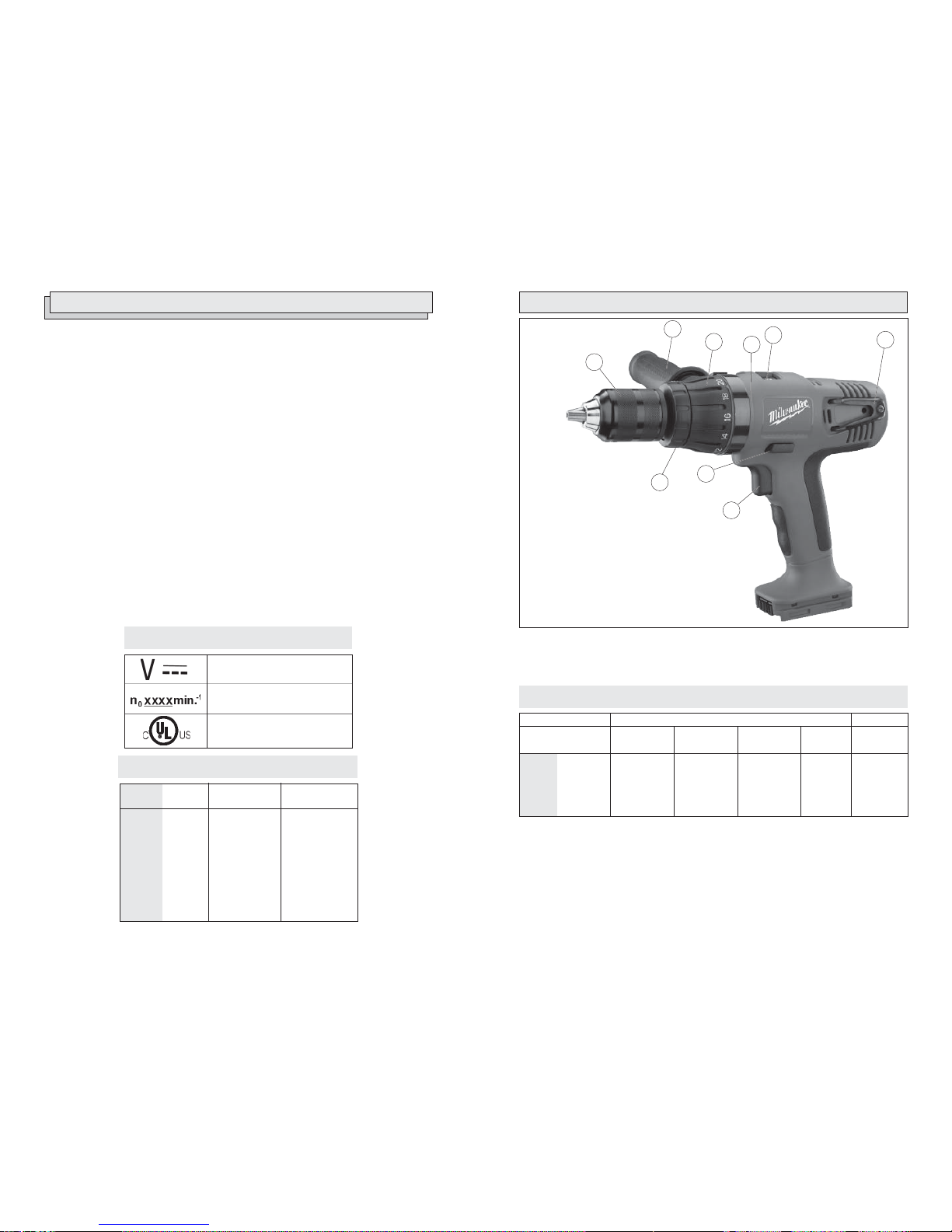
FUNCTIONAL DESCRIPTION
1. Tool holder
2. Trigger
3. Control switch
4. Hammer/drill selector collar
(Hammer-Drill models only)
5. Keyless chuck
6. Side handle
7. Torque selector collar
8. Side handle ribs
9. Speed selector
Capacities
Steel
1/2"
1/2"
1/2"
1/2"
Wood
Flat Bit
1-1/2"
1-1/2"
1-1/2"
1-1/2"
9
Auger Bit
1-1/8"
1-1/8"
1-1/8"
1-1/8"
Hole Saw
2-1/8"
2-1/8"
2-1/8"
2-1/8"
Screws
(dia.)
1/4"
1/4"
1/4"
1/4"
Masonry
N/A
1/2"
N/A
1/2"
0615-20
0617-20
0625-20
0627-20
SPECIFIC SAFETY RULES
1. Maintain labels and nameplates. These carry important information. If unreadable or
missing, contact a MILWAUKEE service facility for a free replacement.
2. WARNING: Some dust created by power sanding, sawing, grinding, drilling, and other
construction activities contains chemicals known to cause cancer, birth defects or other
reproductive harm. Some examples of these chemicals are:
• lead from lead-based paint
• crystalline silica from bricks and cement and other masonry products, and
• arsenic and chromium from chemically-treated lumber.
Your risk from these exposures varies, depending on how often you do this type of work.
To reduce your exposure to these chemicals: work in a well ventilated area, and work
with approved safety equipment, such as those dust masks that are specially designed
to fi lter out microscopic particles.
3. Use auxiliary handles supplied with the tool. Loss of control can cause personal
injury.
4. Wear ear protectors with impact drills. Exposure to noise can cause hearing loss.
5. Hold tools by insulated gripping surfaces when performing an operation where the
cutting tool may contact hidden wiring or its own cord. Contact with a “live” wire will
make exposed metal parts of the tool “live” and shock the operator.
6. Keep hands away from all cutting edges and moving parts.
Specifi cations
Cat. No.
0615-20
0617-20
0625-20
0627-20
Volts DC
14.4
14.4
18
18
No Load RPM
Low 0-500
High 0-1700
Low 0-500
High 0-1700
Low 0-500
High 0-1700
Low 0-500
High 0-1700
No Load Blows
per Minute
N/A
Low 0-7500
High 0-25500
N/A
Low 0-7500
High 0-25500
8
Symbology
Volts Direct Current
No Load Revolutions
per Minute (RPM)
Underwriters Laboratories, Inc.,
United States and Canada
6 7
Inserting Battery Pack into Tool
The battery pack may feel warm after the
charging cycle. If it is warm, maximize the
output of the battery by allowing it to cool for a
few minutes before inserting it into the tool.
Battery pack can be inserted into the tool
in two ways.
1. For working in restricted spaces, insert
the battery pack from the front by sliding
battery pack into the body of the tool.
Insert the battery pack until the battery
latches lock.
2. For optimum weight distribution and
balance, insert the battery pack from the
back by sliding the battery pack into the
body of the tool. Insert the battery pack
until the battery latches lock.
3. To remove the battery pack, press in
both battery latches and slide the battery
pack off of the tool.
WARNING
ASSEMBLY
Always lock trigger or remove
battery pack before changing or removing accessories. Only use accessories specifi cally recommended for
this tool. Others may be hazardous.
WARNING
To reduce the risk of injury, always
use a side handle when using this
tool. Always brace or hold securely.
Installing the Side Handle
To install the side handle:
1. Loosen the side handle grip until the ring
is large enough to slide over the torque
selector collar.
2. Rotate the handle to 90° left or 90° right
of the trigger handle.
3. Push the ring tightly against the side
handle ribs on the tool. The indent in the
side handle must fi t over the appropriate
rib.
4. Tighten the side handle grip securely.
5. To remove the side handle, loosen the
side handle grip until the ring is large
enough to slide off the tool.
WARNING
Recharge only with the charger
specifi ed for the battery pack. For
specifi c charging instructions, read
the operator’s manual supplied with
your charger and battery pack.
WARNING
Always remove battery pack before
changing or removing accessories.
Only use accessories specifically
recommended for this tool. Others
may be hazardous.
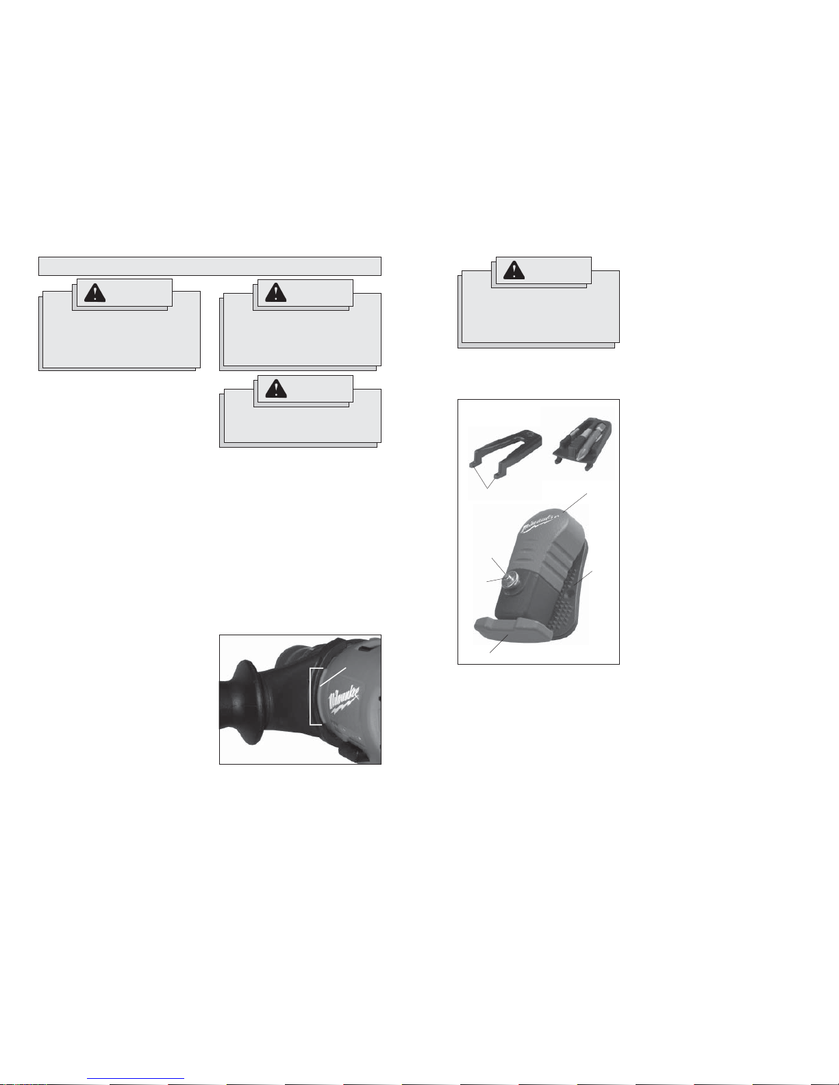
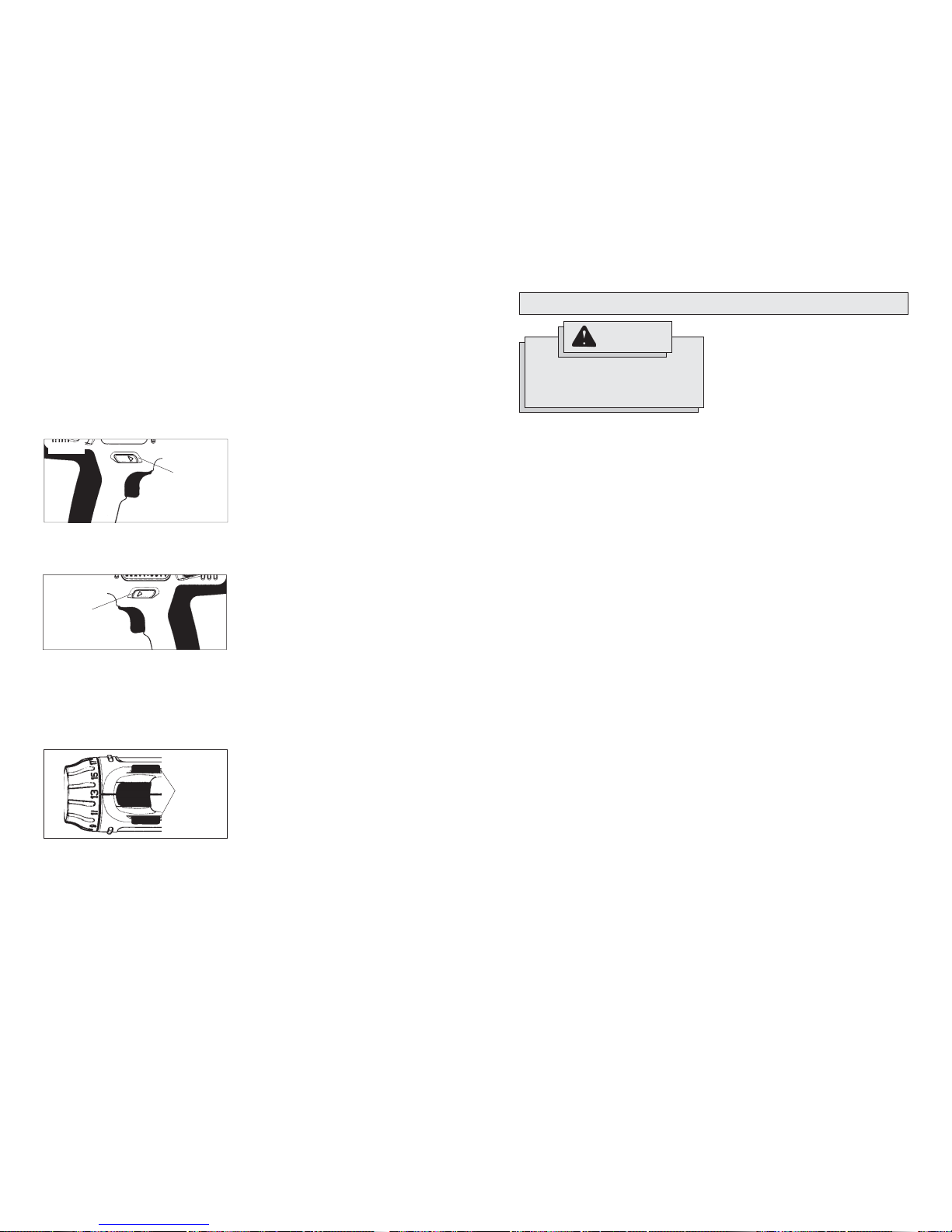
Bit holder
Clip-Lok
TM
System
The Clip-Lok system consists of three
pieces; the belt clip, the tool holder, and the
bit holder.
The system is shipped assembled for righthanded use. To change the assembly for
left-handed use:
1. Remove battery pack.
2. Remove screws holding the tool holder
and the bit holder.
3. Lift the holders at the narrow end and
pull the front tangs out of their slots.
4. Replace the pieces onto the desired
side by sliding the tangs into the slots.
Tighten the screws securely.
Fig. 2
Attaching the Belt Clip
The belt clip can be mounted to tool belts,
bags, buckets, etc. To mount the belt clip:
1. Pull up the clamp release. The clamp
will pop out.
2. Slide the clamp over the tool belt, bag,
bucket, etc.
3. Press in the clamp to tighten.
Using the Clip-Lok Tool Holder
1. To attach the tool to the belt clip, slide
the tool holder over the stud on the belt
clip until it is held in place by the protruding pin.
2. To release the tool from the belt clip,
grasp the tool handle, push down on
the tool release lever with your thumb,
and pull up on the tool.
Using the Clip-Lok Bit Holder
The bit holder holds two standard 1/4" hex
shank bits up to two inches long.
1. Insert the bit by pressing it into the
clip.
2. Remove the bit by lifting the tip of the
bit and pulling it out of the clip.
Belt clip
Tool release lever
Stud
Pin
Clamp
Clamp
release
Tool holder
Front tangs
90° left
Side
handle
rib
Indent
Fig. 1
8 9
OPERATION
WARNING
To reduce the risk of injury, wear
safety goggles or glasses with side
shields.
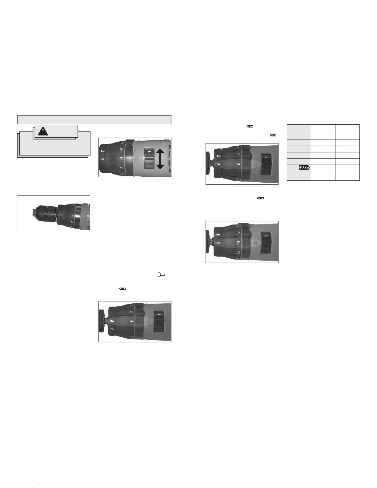
Selecting Speed
The speed selector is on top of the motor
housing. Allow the tool to come to a complete
stop before changing speeds. See “Applications” for recommended speeds under
various conditions.
1. For Low speed (up to 500 RPM), push
the speed selector to the left.
2. For High speed (up to 1700 RPM), push
the speed selector to the right.
Using Keyless Chucks
Your cordless tool is equipped with a spindle
lock. The chuck can be tightened with one
hand, creating higher grip strengths on the
bit.
Always remove the battery pack or lock the
trigger before inserting or removing bits.
1. To open the chuck jaws, turn the sleeve
in the counterclockwise direction.
When using drill bits, allow the bit to
strike the bottom of the chuck. Center
the bit in the chuck jaws and lift it about
1/16" off of the bottom.
When using screwdriver bits, insert the
bit far enough for the chuck jaws to grip
the hex of the bit.
2. To close the chuck jaws, turn the sleeve
in the clockwise direction. The bit is secure when the chuck makes a ratcheting
sound and the sleeve can not be rotated
any further.
3. To remove the bit, turn the sleeve in the
counterclockwise direction.
NOTE: A ratcheting sound may be heard
when the chuck is opened or closed. This
noise is part of the locking feature, and
does not indicate a problem with the chuck's
operation.
Fig. 3
Sleeve
Fig. 5
To Hammer
Fig. 4
Low
High
Selecting Hammer or Drill Action
MILWAUKEE Hammer-Drills are designed
for three operating modes: drilling with
hammering action, drilling only, and driving
screws. To set the operating mode, rotate
the hammer/drill selector collar and torque
selector collar to the desired symbols.
1. To use the hammer-drilling mode
(Fig. 5), rotate the hammer/drill selector
collar until the hammer symbol appears in line with the arrow. Then rotate
the Torque selector collar until the drill
symbol appears in line with the arrow. Apply pressure to the bit to engage
the hammering mechanism.
NOTE: When using carbide bits, do not
use water to settle dust. Do not attempt
to drill through steel reinforcing rods.
This will damage the carbide bits.
Fig. 6
To Drill
Fig. 7
To Drive Screws
2. To use the drilling only mode (Fig. 6),
rotate the hammer/drill selector collar
until the drill symbol appears in line
with the arrow. Then rotate the Torque
selector collar until the drill symbol
mmm
appears in line with the arrow.
The adjustable clutch ,when properly adjusted, will slip at a preset torque to prevent
driving the screw too deep into different
materials and to prevent damage to the
screw or tool.
3. To use the driving screws mode
(Fig. 7), rotate the hammer/drill selector
collar until the drill symbol appears
in line with the arrow. Then rotate the
torque selector collar until the desired
clutch setting appears in line with the
arrow.
The torque specifications shown here are approximate values.
NOTE: Because the above settings are only
a guide, use a piece of scrap material to test
the different clutch positions before driving
screws into the workpiece.
Torque
selector
collar setting
1 - 5
6 - 10
11 - 15
16 - 20
Drill
Low
High
0 - 17 in. lbs.
21 - 38 in. lbs.
42 - 60 in. lbs.
65 - 85 in. lbs.
460 in. lbs.
160 in. lbs.
0615-20
& 0617-20
Torque
0 - 17 in. lbs.
21 - 38 in. lbs.
42 - 60 in. lbs.
65 - 85 in. lbs.
495 in. lbs.
175 in. lbs.
0625-20
& 0627-20
Torque
10 11
For reverse (counterclockwise) rotation,
push in the control switch from the left side
of the tool (Fig. 9). Check direction of rota-
tion before use.
Using Control Switch
The control switch may be set to three positions: forward, reverse and lock. Due to a
lockout mechanism, the control switch can
only be adjusted when the ON/OFF switch
is not depressed. Always allow the motor to
come to a complete stop before using the
control switch.
For forward (clockwise) rotation, push in the
control switch from the right side of the tool
(Fig. 8). Check the direction of rotation
before use.
Push in
for forward
Fig. 8
Fig. 9
Push in
for reverse
To lock the trigger, push the control switch
to the center position (Fig. 10). The trigger
will not work while the control switch is in
the center locked position. Always lock the
trigger or remove the battery pack before
performing maintenance, changing accessories, storing the tool and any time the tool
is not in use.
Fig. 10
Push to
center
position to
lock trigger
Starting, Stopping and Controlling
Speed
1. To start the tool, grasp the handle fi rmly
and pull the trigger.
2. To vary the speed, increase or decrease
the pressure on the trigger. The further
the trigger is pulled, the greater the
speed.
3. To stop the tool, release the trigger.
Make sure the bit comes to a complete
stop before laying the tool down.
Drilling
Set both the hammer/drill and torque selector
collars to the drill positions.
Place the bit on the work surface and apply fi rm pressure before starting. Too much
pressure will slow the bit and reduce drilling
effi ciency. Too little pressure will cause the
bit to slide over the work area and dull the
point of the bit.
If the tool begins to stall, reduce pressure
slightly to allow the bit to regain speed. If
the bit binds, reverse the motor to free the
bit from the workpiece.
APPLICATIONS
WARNING
To reduce the risk of electric shock,
check work area for hidden pipes
and wires before drilling or driving
screws.
Drilling in Wood, Composition Materials
and Plastic
When drilling in wood, composition materials
and plastic, start the drill slowly, gradually
increasing speed as you drill. When drilling
into wood, use wood augers or twist drill bits.
Always use sharp bits. When using twist drill
bits, pull the bit out of the hole frequently to
clear chips from the bit fl utes. To reduce the
chance of splintering, back work with a piece
of scrap wood. Select low speeds for plastics
with a low melting point.
Drilling in Metal
When drilling in metal, use high speed steel
twist drills or hole saws. Use a center punch
to start the hole. Lubricate drill bits with cutting oil when drilling in iron or steel. Use a
coolant when drilling in nonferrous metals
such as copper, brass or aluminum. Back
the material to prevent binding and distortion
on breakthrough.
Drilling in Masonry
When drilling in masonry, select the hammerdrill operating mode (hammer-drills only).
Use high speed carbide-tipped bits. Drilling
soft masonry materials such as cinder block
requires little pressure. Hard materials like
concrete require more pressure. A smooth,
even fl ow of dust indicates the proper drill-
ing rate. Do not let the bit spin in the hole
without cutting. Do not use water to settle
dust or to cool bit. Both actions will damage
the carbide.
Driving Screws and Nut Running
Drill a pilot hole when driving screws into
thick or hard materials. Set the torque selector collar to the proper position and set
the speed to low. Use the proper style and
size screwdriver bit for the type of screw
you are using.
With the screwdriver bit in the screw, place
the tip of the screw on the workpiece and
apply fi rm pressure before pulling the trig-
ger. Screws can be removed by reversing
the motor.
Overloading
Continuous overloading may cause permanent damage to tool or battery pack.
12 13
Bit Binding
A high rotational force occurs when a bit
binds. If the bit binds, the tool will be forced
in the opposite direction of the bit rotation.
Bits may bind if they are misaligned or when
they are breaking through a hole. Wood
boring bits can also bind if they run into
nails or knots. Be prepared for bit binding
situations.
WARNING
High rotational force. To reduce the
risk of injury, always hold or brace
securely. Always use side handle
on tools.
To reduce the chance of bit binding:
• Use sharp bits. Sharp bits are less likely
to bind when drilling.
• Use the proper bit for the job. There are bits
that are designed for specifi c purposes.
• Use caution when drilling pitchy, knotty,
wet or warped material or when drilling in
material that may contain nails.
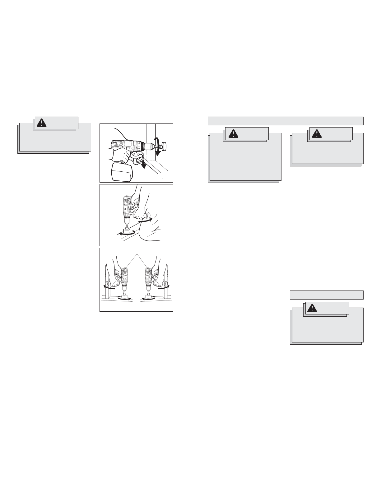
Typical Bracing Methods
Fig. 11
Reaction
Fig. 13
Bracing against a stud
Reverse rotation
Reaction
Forward rotation
Fig. 12
Forward
rotation
Bracing against your leg
Reaction
Forward rotation
Bracing against
the fl oor
WARNING
To reduce the risk of injury, always
unplug the charger and remove the
battery pack from the charger or
tool before performing any maintenance. Never disassemble the tool,
battery pack or charger. Contact a
MILWAUKEE service facility for ALL
repairs.
Keep your tool, battery pack and charger in good repair by adopting a regular
maintenance program. After six months
to one year, depending on use, return the
tool, battery pack and charger to a
MILWAUKEE service facility for:
• Lubrication
• Mechanical inspection and cleaning
(gears, spindles, bearings, housing,
etc.)
• Electrical inspection (battery pack,
charger, motor)
• Testing to assure proper mechanical and
electrical operation
Maintaining Tool
If the tool does not start or operate at full power with a fully charged battery pack, clean
the contacts on the battery pack. If the tool
still does not work properly, return the tool,
charger and battery pack, to a MILWAUKEE
service facility for repairs.
MAINTENANCE
WARNING
To reduce the risk of personal injury
and damage, never immerse your
tool, battery pack or charger in liquid
or allow a liquid to fl ow inside them.
Cleaning
Clean dust and debris from charger and tool
vents. Keep tool handles clean, dry and free
of oil or grease. Use only mild soap and a
damp cloth to clean the tool, battery pack
and charger since certain cleaning agents
and solvents are harmful to plastics and other
insulated parts. Some of these include gasoline, turpentine, lacquer thinner, paint thinner ,
chlorinated cleaning solvents, ammonia and
household detergents containing ammonia.
Never use fl ammable or combustible sol-
vents around tools.
Repairs
For repairs, return the tool, battery pack and
charger to the nearest service center listed on
the back cover of this operator's manual.
ACCESSORIES
Always remove battery pack before
changing or removing accessories.
Only use accessories specifi cally
recommended for this tool. Others
may be hazardous.
WARNING
For a complete listing of accessories refer to
your MILWAUKEE Electric T ool catalog or go
on-line to www.milwaukeetool.com. T o obtain
a catalog, contact your local distributor or a
service center listed on the back cover of this
operator’s manual.
 Loading...