

Milwaukee LMDVT-3328CNM User Manual
US
WARNINGS
• Hot! Do not touch! The glass and
surfaces of this appliance will be hot
during operation and will retain heat
for a while after shutting off the appliance. Severe burns may result.
• Carefully supervise children in the
same room as appliance.
• If small children are present in the home, it is
recommended that this appliance be fitted with
a screen door or screen panel kit. See
Pages
13 & 14 for ordering information.
WARNING: IF THE INFORMATION IN THIS MANUAL
IS NOT FOLLOWED EXACTLY, A FIRE OR EXPLOSION MAY RESULT CAUSING PROPERTY DAMAGE,
PERSONAL INJURY OR LOSS OF LIFE.
Do not store or use gasoline or other flammable
vapors or liquids in the vicinity of this or any
other appliance.
CARE AND OPERATION
INSTRUCTIONS
DIRECT VENT MERIT™
LMDV-33/35/40 SERIES
DIRECT-VENT GAS FIREPLACE HEATERS
P/N 875,028M REV. E 02/2008
MODELS
Millivolt Models Electronic Models
LMDVT-3328CNM
LMDVT-3328CPM
LMDVR-3328CNM
LMDVR-3328CPM
INSTALLER: Leave this manual with the appliance.
CONSUMER: Retain this manual for future reference.
AVERTISSEMENT: ASSUREZ-VOUS DE BIEN
SUIVRE LES INSTRUCTIONS DONNÉ DANS CETTE
NOTICE POUR RÉDUIRE AU MINIMUM LE RISQUE
D'INCENDIE OU POUR ÉVITER TOUT DOMMAGE
MATÉRIEL, TOUTE BLESSURE OU LA MORT.
LMDV-3530CNM
LMDV-3530CPM
LMDV-4035CNM
LMDV-4035CPM
LMDVT-3328CNE
LMDVR-3328CNE
LMDV-3530CNE
LMDV-4035CNE
WHAT TO DO IF YOU SMELL GAS:
• Do not light any appliance.
• Do not touch any electrical switch; do not
Use any phone in your building.
• Immediately call your gas supplier from a
neighbor’s phone. Follow your gas supplier's
instructions.
• If your gas supplier cannot be reached, call
the fire department.
Installation and service must be performed by
a qualified installer, service agency or the gas
supplier.
OTL Report No. 116-F-31-5
A French manual is available upon request. Order P/N 875,028CF
Ce manuel d’installation est disponible en francais, simplement en
faire la demande. Numéro de la pièce 875,028CF
POUR VOTRE SÉCURITÉ: Ne pas entreposer ni
utiliser d'essence ni d'autre vapeurs ou liquides
inflammables dans le voisinage de cet appareil ou
de tout autre appareil.
POUR VOTRE SÉCURITÉ: Que faire si vous sentez
une odeur de gaz:
• Ne pas tenter d'allumer d'appareil.
• Ne touchez à aucun interrupteur. Ne pas vous
servir des téléphones se trouvant dans le batiment où vous vous trouvez.
• Evacuez la piéce, le bâtiment ou la zone.
• Appelez immédiatement votre fournisseur de
gaz depuis un voisin. Suivez les instructions
du fournisseur.
• Si vous ne pouvez rejoindre le fournisseur de
gaz, appelez le service dos incendies.
L'installation et service doit être exécuté par un
qualifié installeur, agence de service ou le fournisseur de gaz.
CONGRATULATIONS!
In selecting this LENNOX Direct-Vent Gas Appliance you have chosen the finest and most
dependable fireplace to be found anywhere. Its a beautiful, prestigious alternative to a
wood burning fireplace. Welcome to a Family of tens of thousands of satisfied LENNOX
Fireplace Owners.
Please carefully read and follow all of the instructions found in this manual. Please pay
special attention to the safety instructions provided in this manual. The Homeowner's
Care and Operation Instructions included here will assure that you have many years of
dependable and enjoyable service from your LENNOX product.
These appliances are designed to operate on natural
gas or propane gas only. The use of other fuels or
combination of fuels will degrade the performance
of this system and may be dangerous.
Millivolt Models - BTU Input
Millivolt models come standard with the manu
ally-modulated gas valve; flame appearance and
heat output can be controlled at the gas valve.
The BTU Input for millivolt models is shown in
Tables 1 & 2:
-
TABLE OF CONTENTS
Introduction ......................................Page 2
General Information ..........................
Gas Controls Access .........................
Operation/Care of Your Appliance .....
Variable Flame Adjustment ................
Maintenance ......................................Page 5
Front Glass Enclosure Panel,
Removal and Installation .................
Install Vermiculite, Volcanic Stone,
Embers & Logs .................................
Burner Flame Appearance & Sooting
Burner Flame Adjustments ................
Millivolt Appliance Checkout .............
Electronic Appliance Checkout ..........
Product Reference Information .........
Warranty ...........................................Page 11
Wiring Diagrams ...............................
Accessory Components ....................
Lighting Instructions – Millivolt ........
Lighting Instructions – Electronic .....
Maintenance Schedule ......................
Troubleshooting Guide – Millivolt
Troubleshooting Guide – Electronic ..
Replacement Parts List .....................
This manual is part of a set of two supporting
this product. Refer to manual 850,029M for
Installation Instructions.
INTRODUCTION
The Fireplace models covered in this manual
are Direct-Vent sealed combustion gas fireplace
heaters designed for residential application.
Direct-Vent appliances operate with the combustion chamber completely isolated from the
indoor environment. All air for combustion is
brought in from the outside and exhaust gases
are vented through the same direct vent, co-axial
(intake/exhaust) vent system.
The Millivolt appliances have a millivolt gas
control valve with piezo ignition system provides
safe, efficient operation. If any optional accessories which require electrical power are being
installed, the electrical power must be provided
at the time of appliance installation.
2
......Page 23
Page 2
Page 3
Page 3
Page 4
Page 6
Page 7
Page 10
Page 10
Page 11
Page 11
Page 11
Page 12
Page 13
Page 18
Page 20
Page 22
Page 23
Page 26
The Electronic appliances have an electronic
intermittent pilot system provides safe, efficient
operation. External electrical power is required
to operate these appliances.
These appliances comply with National Safety
Standards and are tested and listed by OmniTest Laboratories (Report No. 116-F-31-5) to
ANSI ZZ21.88b (in Canada, CSA-2.33b), and
CAN/CGA-2.17-M91 in both USA and Canada,
as vented gas fireplace heaters.
The Installation must conform to local codes
or, in the absence of local codes, with the
National Fuel Gas Code, ANSI Z223.1/NFPA
54-latest edition, or the Natural Gas and
Propane Installation Code, CSA B149.1-latest
edition. The appliance, when installed, must
be electrically grounded in accordance with
local codes or, in the absence of local codes,
the latest edition of the National Electrical Code,
ANSI/NFPA 70, or the Canadian Electrical Code,
CSA C22.1 - latest editions.
GENERAL INFORMATION
Note: Installation and repair should be performed by a qualified service person. The
appliance should be inspected annually by a
qualified professional service technician. More
frequent inspections and cleanings may be
required due to excessive lint from carpeting,
bedding material, etc.
It is imperative that the control compartment,
burners and circulating air passage ways of
appliance be kept clean. See Maintenance
instructions on Page 5.
S'assurer que le brùleur et le compartiment des
commandes sont propres. Voir les instructions
d'installation et d'utilisation qui accompagnent
l'appareil.
Provide adequate clearances around air open
ings and adequate accessibility clearance for
service and proper operation. Never obstruct
the front openings of the appliance.
Due to high temperatures the appliance should
be located out of traffic and away from furniture
and draperies. Locate furniture and window
coverings accordingly.
These fireplaces are designed as supplemental
heaters. Therefore, it is advisable to have an alter
nate heat source when installed in a dwelling.
Input (BTU) MAnnually-Modulated Gas
Valves (millivolt models)
NATURAL GAS
Models Input Rate
(BTU/HR)
LMDVT-3328CNM
LMDVR-3328CNM
LMDV-3530CNM
LMDV-4035CNM
17,500 high
11,700 low
20,000 high
12,800 low
27,000 high
18,500 low
Table 1
Input (BTU) MAnnually-Modulated Gas
Valves (millivolt models)
PROPANE GAS
Models Input Rate
(BTU/HR)
LMDVT-3328CPM
LMDVR-3328CPM
LMDV-3530CPM
LMDV-4035CPM
17,500 high
14,000 low
20,000 high
15,200 low
27,000 high
21,500 low
Table 2
Electronic Models -
Electronic models have a fixed rate gas valve.
The BTU Input for electronic models is shown
Table 3:
in
Input (BTU) - Fixed Rate
(electronic models)
-
-
NATURAL GAS & PROPANE GAS
Models Input Rate
LMDVT-3328CNE
LMDVR-3328CNE
LMDV-3530CNE
LMDV-4035CNM
LMDV-4035CPM
Table 3
(BTU/HR)
17,500
20,000
28,000
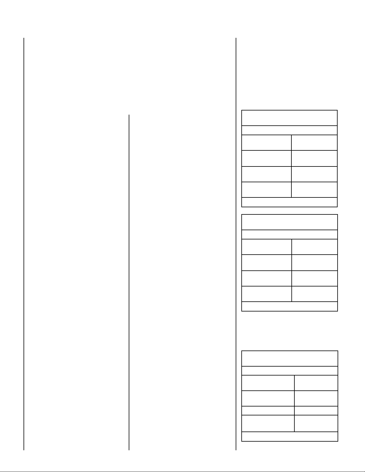
Gas Pressure -
Tables 4, 5 and 6 show the appliances' gas
pressure requirements.
Inlet Gas Supply Pressure
(all models)
Fuel # Minimum Maximum
Natural Gas
Propane
5.0" WC
(1.24 kPa)
11.0" WC
(2.74 kPa)
10.5" WC
(2.61 kPa)
13.0" WC
(3.23 kPa)
Table 4
Manifold Gas Supply Pressure
(millivolt models)
Fuel # Low High
Natural
Gas
Propane
(Lo) 2.2" WC
(.55 kPa)
(Lo) 6.3" WC
(1.57 kPa)
(Hi) 3.5" WC
(.87 kPa)
(Hi) 10.0" WC
(2.49 kPa)
Table 5
Manifold Gas Supply Pressure
(electronic models)
Fuel # Fixed
Natural Gas
Propane
3.5" WC
(.87 kPa)
10.0" WC
(2.49 kPa)
Table 6
Test gauge connections are provided on the
front of the millivolt gas control valve, identified
IN for the inlet and OUT for the manifold side
(see
Figures 4 or 5 on Page 4). A 1/8" NPT
Test gauge connection is provided at the inlet
and outlet (manifold) ports on the electronic gas
control valve (see
Figure 3 on Page 4).
These appliances must be isolated from the
gas supply piping system (
by closing their
individual manual shut-off valve) during any
pressure testing of the gas supply piping
system at test pressures equal to or
less than
1/2 psig (3.5 kPa).
These appliances and their individual shut-off
must be disconnected from the gas
valves
supply piping system during any pressure
testing of that system at pressures
greater
than 1/2 psig (3.5 kPa).
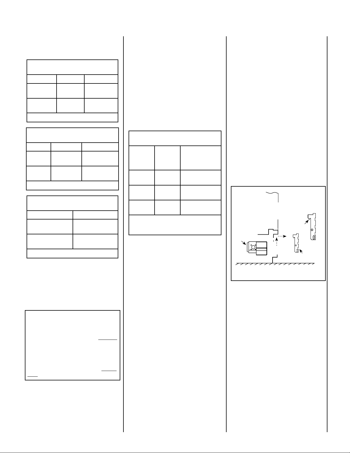
Orifice Sizes - Sea Level to High Altitude
(All Models): These appliances are tested and
approved for installations at elevations of 0-4500
feet (0-1372 meters) above sea level using the
standard burner orifice sizes (marked with an
"*" in
Table 7).
At the time of installation, it must be determined
if the appliance needs to be derated. Contact
your local gas supplier for deration requirements
for your area.
Deration - At higher elevations, the amount of
BTU fuel value delivered must be reduced by
either using gas that has been derated by the gas
company or by changing the burner orifice to a
smaller size as regulated by the local authorities
having jurisdiction and by the (USA) National
Fuel Gas Code NFPA 54/ANSI Z223.1 - latest
edition or, in Canada, the CAN1-B149.1 and .2
codes - latest edition.
Burner Orifice Sizes
Elevation 0-4500 feet ( 0-1372 meters)
Model
Series
LMDVT-3328
LMDVR-3328
LMDV-3530
LMDV-4035
* Standard size installed at factory
• Part /Cat. Number
Natural
Gas
drill size
(inches)
#45 (.082")
39L66 •
#44 (.086")
60J80 •
#37 (.104")
24M10 •
*
*
*
Propane
Gas
drill size (inches)
1.2 mm (.048")
99K78 •
#55 (.052")
19L52 •
1/16" (.0625")
21L01 •
*
*
*
Table 7
Burn-in Period
During the first few fires of this appliance there
will be some odor due to the curing of the
paint and burning off of lubricants used in the
manufacturing process.
Depending on your use, the burn-in period may
take a few hours or a few days.
KEEP YOUR HOUSE WELL VENTILATED
DURING THE CURING PROCESS. THE ODOR
AND HAZE EMITTED DURING THE CURING
PROCESS CAN BE QUITE NOTICEABLE AND
MAY SET OFF A SMOKE DETECTOR.
If an optional blower is installed, Do not turn it
on during the Burn-In period.
A white film may develop on the glass front
during the first few fires as part of the curing
process. The glass should be kept clean during
the first two weeks of use to prevent the film from
baking on (making it very difficult to remove).
See
Cleaning Glass on Page 5.
Gas Controls/Control Compartment
Access
The gas controls can be found behind the control
compartment access door.
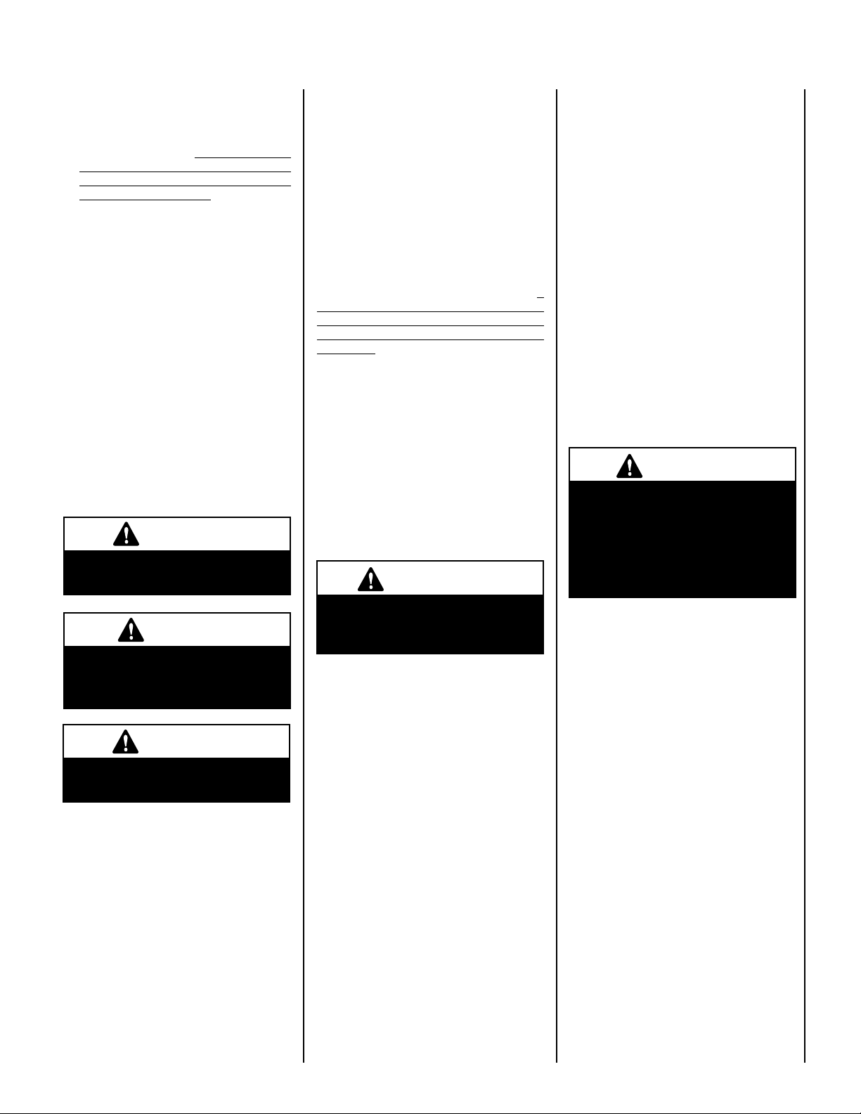
Removing Control Compartment Door:
Open the door by gently liftint it upward until the
hook catches on boths sides clear the locating
slots. Then pull door out to remove.
On millivolt systems, the piezo igniter, HI/LO
flame adjustment knob, and pilot and main
gas OFF/ON control knob are located below
the glass panel enclosure. The gas valve for
electronic systems is also located below the
glass enclosure panel. See
Figure 1.
Reinstalling Control Compartment Door:
To reinstall, insert the hook catches on each side
of the door into the corresponding slots in the
control compartment opening, then gently push
forward and slide down until it locks in place.
Lift the Lower Control
OPENING CONTROL
COMPARTMENT DOOR
Control Valve
Compartment Door
up and pull out to
remove.
Hook Catch
Out
Up
Lower Control
Compartment Door
Figure 1
OPERATION AND CARE OF YOUR
APPLIANCE
The standard controls for appliance operation are located behind the panel below the
appliance front glass enclosure panel (see
Figure 1). Optional control switches are also
available (see
Remote Control or Wall Thermostat).
Operation of millivolt and electronic gas con
trol systems are different. Before lighting and
operating your appliance determine if you have
a millivolt or electronic appliance. Familiarize
yourself with the gas control valve that your
appliance uses. Refer to
to the gas control valve.
Page 13 - Remote Wall Switch,
Figure 1 for access
-
NOTE: DIAGRAMS & ILLUSTRATIONS ARE NOT TO SCALE.
3
Millivolt Appliances - Appliances with
O
N
O
F
F
P
I
L
O
T
L
O
H
I
OFF
ON
OFF
ON
H
I
L
O
W
H
T
P
T
H
T
P
T
P
I
L
O
T
P
I
L
O
T
O
N
ti
O
F
F
IN
OUT
OFF
ON
OFF
ON
F
F
O
N
I
P
S
I
NO
L
O
R
T
N
O
C
G
I
N
T
I
ER
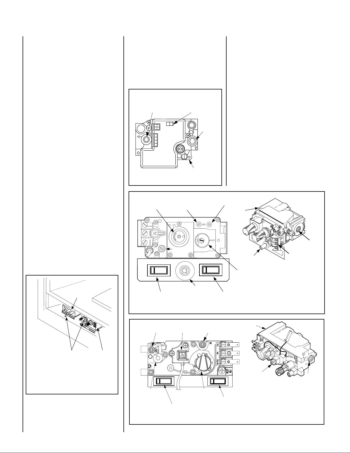
Millivolt systems will be fitted with the gas
control valve shown in Figures 4 or 5.
Electronic Appliances - Appliances with
electronic systems will be fitted with the
electronic valve shown in
Figure 3.
Millivolt Appliances - To light millivolt appliances refer to the detailed lighting instructions
found on Pages 18 & 19 . Millivolt appliance
lighting instructions may also be found on the
pull out lighting instruction labels attached to
the gas control valve.
Millivolt appliances are fitted with an OFF/ON
Rocker Switch located behind the control
compartment access door, below the appliance front glass enclosure panel (see Figure 2
for location). Once the pilot is lit, the OFF/ON
rocker switch will control the appliance OFF/ON
burner operation. To operate: Toggle the switch
between its ON and OFF positions.
If your millivolt appliance is equipped with an
optional remote switch kit (wall switch, remote
control or wall thermostat) and the pilot is lit,
the appliance main burner may be turned on
and off using the optional switch. When using
an optional remote switch, turn off the standard
OFF/ON switch.
Electronic Appliances -
To light electronic appliances refer to the detailed
lighting instructions found on
Pages 20 & 21
of these instructions. Electronic appliance
lighting instructions may also be found on the
pull out lighting instruction labels attached to
the gas control valve.
Honeywell Electronic Gas Valve
Manifold Pressure
Port
Figure 3
HI/LO Variable
Flame Height
Adjustment
ON/OFF Switch
Inlet
Pressure
Port
Electronic Gas
Control Valve
Manifold Pressure Tap
Inlet Pressure Tap
If your electronic appliance is equipped with an
optional remote wall switch or remote control kit
the appliance main burner may be turned on and
off with the wall switch or remote control.
If your electronic appliance is not equipped
with a wall switch or remote control, the main
burner must be turned off and on with the gas
control switch. Toggle the switch from ON to
OFF to operate the main burner .
Variable Flame Height Adjustment
(Millivolt Appliances only)
1. All Millivolt appliances are equipped with a
variable gas control valve. Flame height for
these models may be adjusted through a
range between fixed low and high settings
while the appliance is in operation. Adjust
the flame height as desired after lighting the
appliance by rotating the variable adjustment
control knob (HI/LO) located on the front of
the valve (refer to
2. During the first initial burns of these appli-
ances, there will be some odor emitted (see
Burn-In Period on Page 3 ).
Gas
Inlet
Figures 4 & 5 ).
Note: To prevent excessive resistance in burner
circuit (which can cause burner operation prob
lems), only one burner control switch should be
wired to valve. Therefore, if an optional control
switch is installed, the standard Off/On switch
and wires should be removed.
SIT Gas Valve
Shown with control
compartment door
removed
Piezo Igniter
Sit and Honeywell Millivolt Gas Valve
Showing Piezo Igniter Location (Each Unit is
Equipped with Only One of these Gas Valves)
Figure 2
4
Honeywell
Gas Valve
-
Pilot Adjustment
Screw
Piezo Igniter
Terminals
TPTH,TP & TH
Gas
Outlet
Main Gas
Control Knob
OFF/PILOT/ON
Piezo Igniter
Optional Burner OFF/ON
Rocker Switch
Figure 4
Optional Blower OFF/ON
Rocker Switch
SIT Millivolt Gas Valve
Gas
Manifold Pressure
Piezo Igniter
Inlet Pressure Tap
Outlet
Tap
Piezo Igniter
Gas
Inlet
HI/LO Variable
Flame Height
Adjustment
Optional Burner OFF/ON
Main Gas
Control Knob
OFF/PILOT/ON
Optional Blower OFF/ON
Rocker Switch
Rocker Switch
Figure 5
NOTE: DIAGRAMS & ILLUSTRATIONS ARE NOT TO SCALE.
Honeywell Millivolt Gas Valve
3. Keep the lower control compartment clean
by vacuuming or brushing at least twice a
year. More frequent cleaning may be required
due to excessive lint from carpeting, bedding
materials, pet hair, etc. It is very important
that the control compartments, burners
and circulating air passageways of the
appliance are kept clean.
4. Always turn off gas to the pilot (millivolt
appliances) and let the appliance cool down
before cleaning. Before re-lighting, refer
to the lighting instructions in this manual.
Lighting instructions may also be found
on the pull out lighting instruction labels
attached to the gas control valve.
5. Always keep the appliance area clear and
free from combustible materials, gasoline
and other flammable liquids.
6. Remember, Millivolt appliances have a continu-
ous burning pilot flame. Exercise caution when
using products with combustible vapors.
MAINTENANCE
(See Maintenance Schedule,
Refer to the maintenance schedule for maintenance
tasks, procedures, periodicity and by whom they
should be performed. Always verify proper opera
tion of the appliance after servicing.
WARNING
Page 22)
Turn off gas and electrical power
before servicing the appliance.
CAUTION
Wear gloves and safety Glasses
for protection while doing
required maintenance.
IMPORTANT
Always verify proper operation
after servicing.
Before re-lighting the fireplace, refer to the
lighting instructions in this manual. Instruc
tions are also found on pull-out panels
located below the glass door in the control
compartment.
Inspect Venting System
The appliance and venting system should be
thoroughly inspected before initial use and
at least annually by a qualified service techni
cian (inspection should include ensuring that
exhaust or intake passages are unobstructed
and vent components are properly assembled
and not damaged).
If the venting system is disassembled for any
reason, a qualified service technician should
follow vent installation instructions for proper
reassembly and proper sealing of the venting
system components. However, more frequent
periodic inspections and cleanings should be
performed by the homeowner.
Clean Lower Control Compartment
Keep lower control compartment clean by
vacuuming or brushing it out at least twice a
year (also clean the air venturi with a brush or
wire). More frequent cleaning may be required
due to accumulation of lint from carpeting,
bedding materials, pet hair, spider webs, etc. It
is very important that control compartments,
burners, circulating air passageways and air
venturi on the appliance are NOT obstructed
in any way.
Cleaning Glass
(see Front Glass Enclosure Panel, Removal and
Installation on Page 6 )
Note: Clean glass after first two weeks of operation (after Burn-In period is over) and then only
when necessary and when the fireplace is cool.
Wipe surface with clean, dampened, soft cloth.
Follow with dry, soft towel as desired. Take care
not to scratch the glass surface.
The viewing glass should be cleaned periodi
cally to remove any build-up caused from the
following:
IMPORTANT
Do not use abrasive cleaners
on glass. Never clean the glass
when it is hot.
• During start-up, it is normal for condensation to form on the inside of the glass (this
condensation and fog will usually disappear
in a few minutes). The moisture can cause
lint, dust and other airborne particles to cling
to the glass surface.
• Initial curing of the high temperature paint
and burning off of lubricants used in the
manufacturing process may result in a film
on the glass.
• A white coating may form on the glass as a
result of impurities and minerals in the fuel.
-
It is recommended that the glass be cleaned
two or three times during each heating season,
depending on the circumstances present. The
following cleaning solutions are approved for use
to clean glass:
• Non-ammonia based household cleaner
• 50%-50% mix of white vinegar & water
• Gas fireplace/stove glass cleaner
Inspect Glass Gasket - Visually inspect the
gasket on the backside of the glass enclosure
panels. The gasket surface must be clean, free
of irregularities and seated firmly.
Clean Logs And Burner
Carefully remove the logs (use care when han
dling the fiber logs, as they become quite fragile
after curing). Vacuum out any foreign matter
(lint, carbon, etc). on the burner. Ensure the
burner ports are “open.” Remove any carbon
deposits from the under side of the logs using
a vacuum cleaner, or a soft bristled brush (i.e.
paint brush). Note: Improper positioning of
logs can create carbon build-up and will alter
the performance of the appliance.Replacing
Logs -
If the logs become damaged by accident or im
proper handling and need replacement, use only
the proper replacement logs from manufacturer
(see
Pages 26 & 27 for ordering information).
Re-Install Embers, Logs and Vermiculite
- Carefully follow placement instructions on
Pages 7 to 9 ). All logs should fit onto corresponding pins and/or log stoppers. This will
ensure a proper flame and safe combustion.
Inspect Wiring
Refer to wiring diagrams on
WARNING
Page 12.
Label all wires prior to discon-
-
nection when servicing controls. Wiring errors can cause
improper and dangerous operation. Verify proper operation
after servicing.
Inspect and clean all wire connections. Ensure
that there is no melting or damage. Inspection
should include
• Terminals at the Valve
• OFF/ON Switch
• (Optional Control Switch) Wall Thermostat,
Remote Control or Remote Wall Switch Kit
Inspect Burner Flame Appearance
Ensure that the burner flame appearance
resembles the flame shown in
11 and as described in Flame Appearance and
Sooting on Page 10. The Homeowner must
contact a qualified service technician at once
if any abnormal condition is observed.
Small Area Paint Touch-up
The finish of the appliance is a high-qual
ity powdercoat. Only use factory supplied
powdercoat paint kit for touch-ups. Paint is
available at your local authorized Lennox Hearth
Products dealer, cat. no. 90L74. Never attempt
to paint a hot fireplace.
Do not attempt to repaint the appliance until the
finish is completely cured (see
on
Page 3 ). If the surface later becomes stained
or marred, it may be lightly sanded and touched
up with spray paint.
:
Figures 10 &
Burn-In Period
-
-
-
NOTE: DIAGRAMS & ILLUSTRATIONS ARE NOT TO SCALE.
5
Front Glass Enclosure Panel, Removal
and Installation
WARNING
Do not operate appliance with the
glass front removed, cracked or
broken. Replacement of the glass
should be done by a licensed or
qualified service technician.
WARNING
Do not attempt to substitute the
materials used on this door, or
replace cracked or broken glass
with any materials other than
those provided by the appliance
manufacturer.
WARNING
These are direct-vent appliances. They are
designed to operate only when the front glass
enclosure panel is installed. Generally the front
glass enclosure panel should not be removed
except to gain access to the components within
the firebox, and the appliance may only be op
erated without the front glass enclosure panel
in place for very brief periods of time during
appliance checkout and adjustment. Note: The
flame appearance will be diminished while the
front glass enclosure panel is removed.
During this appliance checkout and adjust
ment period, a potential safety hazard exists
- EXERCISE EXTREME CAUTION to prevent
the occurrence of any burn injuries from the
exposed flames or hot surfaces. Also note, that
while the front glass enclosure panel (or any of
the panels) is removed, the flame appearance
will appear to be smaller than normal.
Top Flange on
Glass Door
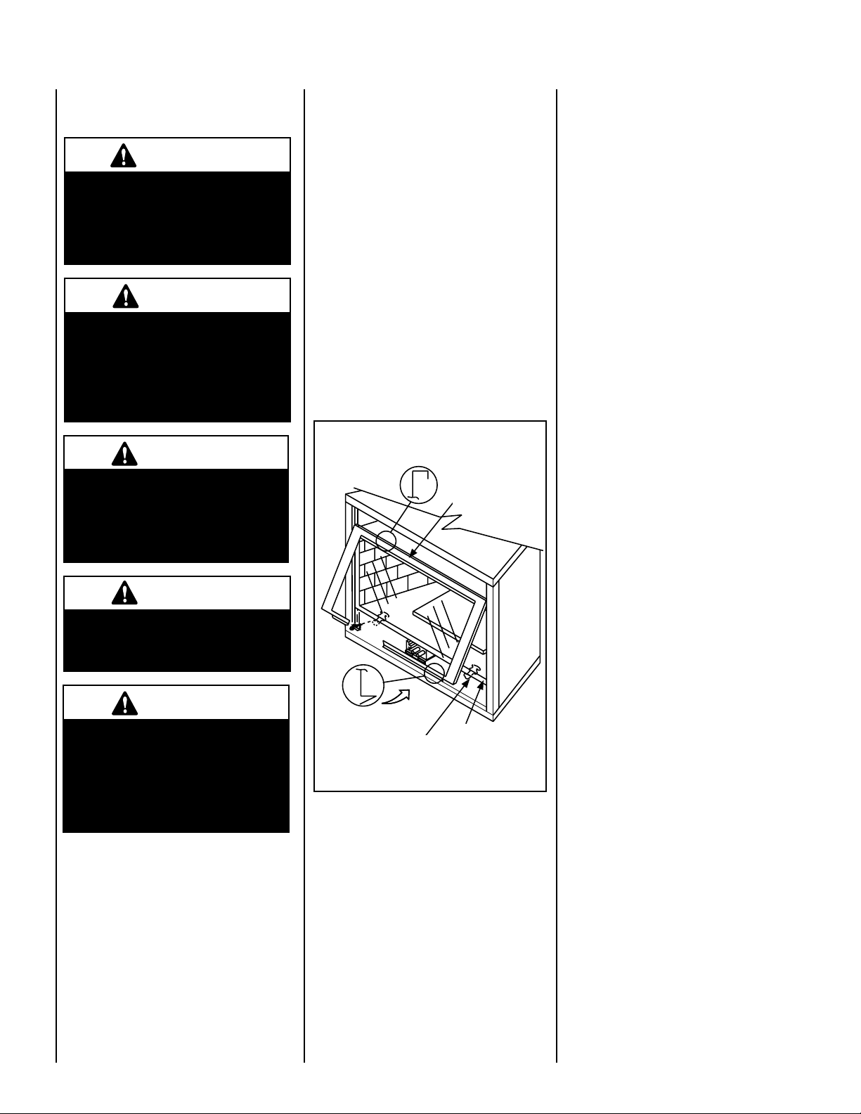
Removing Glass Enclosure Panels
(see Figure 6)
1. Remove the top louver assembly by pulling
it up and out.
-
2. Remove the control compartment access
door (see removal instructions on
- Removing Control Compartment Door).
3. Locate the two (2) latches at the top of the
control compartment. To disengage the two
-
latches from the bottom vee-flange of the
glass enclosure panel, reach for the handles
located towards the back of the latches and
pull the handles down toward the front of
the appliance.
4. Swing the bottom of the door out and raise
it slightly to lift the top flange of the door
frame away from the appliance.
Installing Glass Enclosure Panels
(see Figure 6)
Page 3
Handle this glass with extreme
care! Tempered glass is susceptible to damage – do not scratch
or handle roughly while reinstalling the glass door frame.
WARNING
Do not attempt to touch the front
enclosure glass with your hands
while the fireplace is in use.
WARNING
The glass door of this appliance must only be replaced as a
complete unit as provided by the
manufacturer. Do not attempt to
replace broken, cracked or chipped
glass separately.
Glass Door
Bottom Vee-flange
Glass Door
Glass Door Latch
Firebox Floor
Figure 6 - INSTALLING GLASS DOOR
1. Visually inspect the gasket on the backside
of the glass panel. The gasket surface must
be clean, free of irregularities and seated
firmly.
2. Position the glass enclosure panel in front of
the firebox opening at a 45 degree angle and
engage the top flange over the lip at the top
of the firebox opening.
3. Swing the glass enclosure panel down and
back. Ensure the gasket seats evenly as the
panel draws shut. Engage the Vee-flange at
the bottom of the panel with the latches and
close the latches to secure the panel.
4. Reinstall the control compartment door
see installation instructions on
Reinstalling Control Compartment Door).
See Figure 6.
Page 3,
6
NOTE: DIAGRAMS & ILLUSTRATIONS ARE NOT TO SCALE.
INSTALL VERMICULITE, VOLCANIC
STONE, GLOWING EMBERS AND LOGS
1. Remove the front glass enclosure panel
(see
Removing Glass Enclosure Panels on
this page).
2.
Carefully remove the old logs, embers
volcanic stone and vermiculite from the
firebox. Handle logs carefully to prevent
breakage.
3.
Install Vermiculite - Place some vermiculite
on the firebox floor around the burner (the
entire bag of vermiculite will NOT be used).
See
Figures 8 & 9. DO NOT PLACE ANY
VERMICULITE ON THE BURNER. Mound
up a portion of the vermiculite in front of the
burner.
4. Install decorative volcanic stone - Sprinkle
the decorative volcanic stone (dark colored)
on top of the vermiculite (light colored) in a
pleasing pattern (see
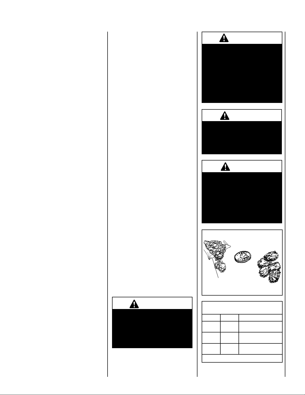
5. Placement of Glowing Embers -
Separate the Embers (rockwool) into pieces
about the size of a quarter (see
Keep the pieces fluffed up, not matted.
Distribute these pieces over the surface of
the burner, as shown in
not use more than is necessary. Ensure that
the main burner slots remain uncovered by
the ember material.
Note: This appliance is provided with enough
Glowing Embers for several applications, do
not use all that is in a new bag at one time. For
best glowing effect, replace the ember material
annually.
6. Placement of Logs and Twigs -
All logs that have locating notches or slots to
help ensure that they are properly positioned.
All top logs that rest on lower logs, do so
over notches, indents or pins. Proper twig
placement is critical to prevent sooting. Twigs
should be placed in the gaps between the flame
peaks and should be positioned so they do not
impinge the flames.
LMDV-3328 & LMDV-3530 - Install as Follows
Figures 8 & 9).
Figure 7).
Figures 8 & 9. Do
1. Place the rear log (A) as shown. Position the
2 notches on the bottom of the log over the
2 corresponding locating brackets against
the back wall of firebox.
2. Place the left log (B) as shown. The notch
on the bottom of the log should fit over the
corresponding locating bracket.
3. Place the right log (E) as shown. The hole
on the back of the log should fit over the
corresponding pin on the rear log (A). Make
sure that the log is positioned so it aligns
to the sides of the gas ports on the corner
of the burner.
4. Place the left center log (C) as shown.
The forked end of the log fits into the cor
responding notch on rear log (A). The slot
on the other end (bottom) of log fits over
the corresponding locating bracket on the
sub-floor.
5. Place the right center log (D) as shown. One
end of the log fits into the corresponding
indent on the right log (E). The slot on
the other end (bottom) of log fits over the
corresponding locating bracket on the subfloor.
LMDV-4035 - Install as Follows
Carefully position the ceramic fiber logs and twigs
over the burner as shown in
should be placed in the order shown and per the
following instructions.
1. Position the center log (C) onto the 2 cor
responding location pins on the burner.
2. Place the rear log (A) as shown. Position the
2 notches on the bottom of the log over the
2 corresponding locating brackets against
the back wall of firebox.
3. Place the left log (B) as shown. The notch
on the bottom of the log should fit over the
corresponding locating bracket.
4. Place the right log (E) as shown. The notch
on the bottom of the log should fit over the
corresponding locating bracket. Make sure
that the log is positioned so it aligns to the
sides of the gas ports on the corner of the
burner.
5. Place the center front log (D) as shown.
The slot in the bottom of the log fits over
the corresponding location bracket on the
sub-floor.
Figure 9. Logs
WARNING
The size and position of the log
set was engineered to give the
appliance a safe, reliable and
attractive flame pattern. Any
attempt to use a different log
set in the fireplace will void
the warranty and will result in
incomplete combustion, sooting, and poor flame quality.
-
WARNING
This appliance is not designed
to burn wood. Any attempt to
do so could cause irreparable
damage to appliance and prove
hazardous to your safety.
WARNING
If logs are not installed according
to the log installation instructions, flame impingement and
improper combustion could
-
occur and result in soot and/or
excessive production of carbon
monoxide (CO), a colorless,
odorless, toxic gas.
Glowing Embers
Separate into Quarter
Size (separate) Pieces
Bag of Glowing
Embers (rockwool)
Figure 7
Carefully position the ceramic fiber logs and twigs
over the burner as shown in
should be placed in the order shown and per the
following instructions.
Figure 8. Logs
WARNING
DO NOT attempt to install the logs
until the appliance installation
has been completed, the gas line
connected and tested for leaks
and the initial burner operation
has been checked out.
NOTE: DIAGRAMS & ILLUSTRATIONS ARE NOT TO SCALE.
REFERENCE
Firebox Accessories/Parts
Cat. No. Model No. Description
88L53 FGE Bag of Glowing Embers
H3696
80L42 FDVS
(1 oz. rockwool)
Vermiculite, Bag (2 liters)
Bag of Decorative
Volcanic Stone
Table 8
7
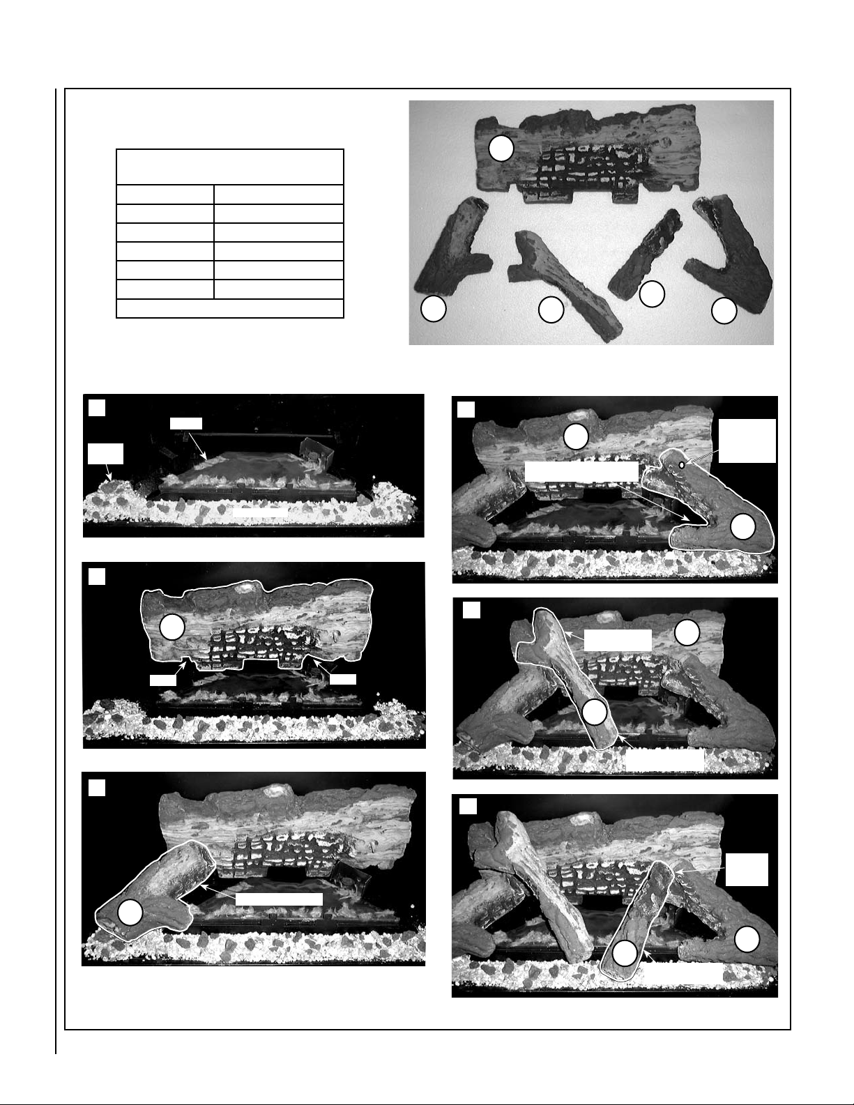
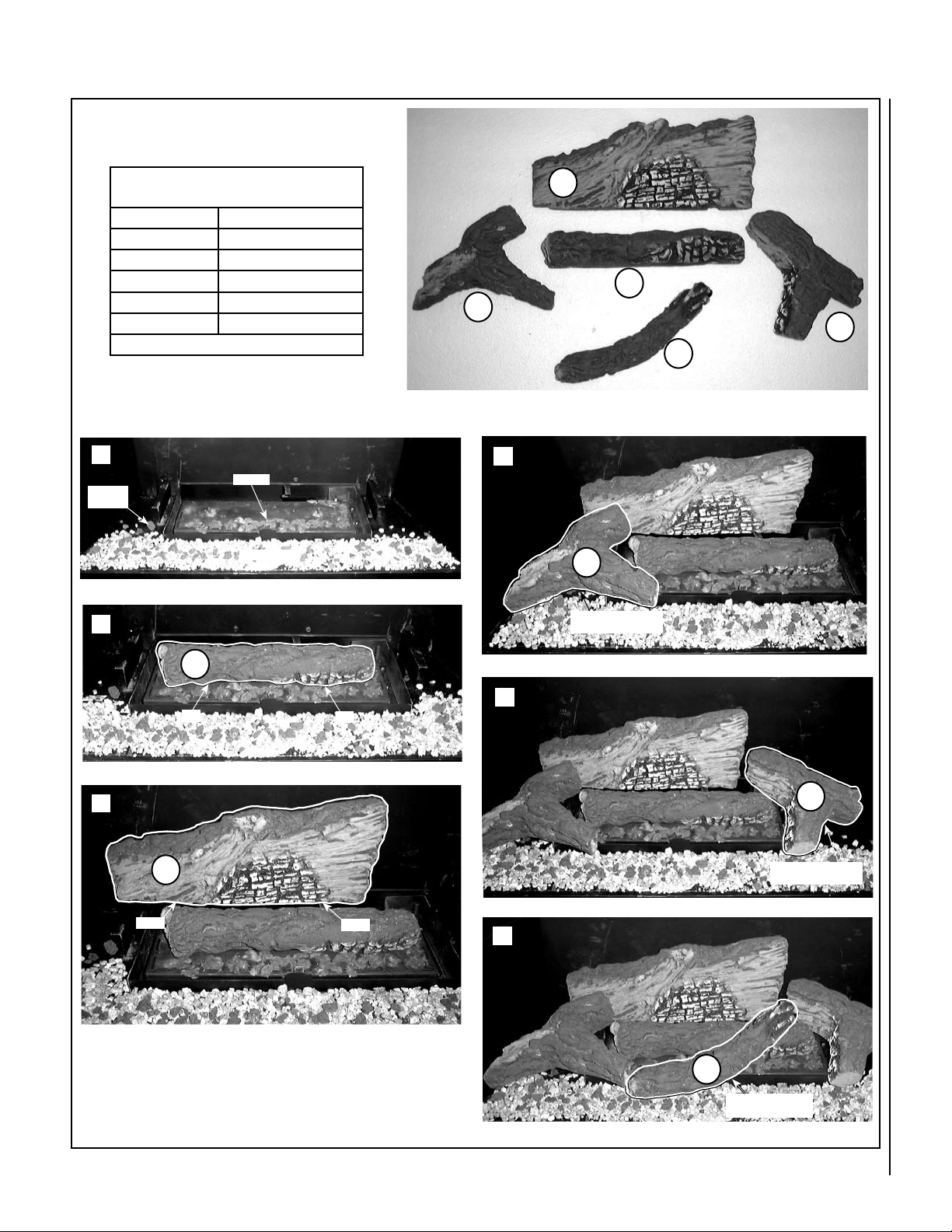
MODEL LMDV-3328 & LMDV-3530
Log Placement Instructions
LOG SET
Catalog Number
* Item
A
B
C
D
E
* Item "letters" above correspond to photos
Install the Embers, Vermiculite, Volcanic Stone and Logs in the order
shown here (1 through 6) and per the instructions on Page 7.
H3366
Description
Log, Rear
Log, Left
Log, Left Center
Log, Right Center
Log, Right
A
D
B
C
E
1
Volcanic
Stone
2
3
DO NOT PLACE EMBERS OVER GAS SLOTS
Embers
Vermiculite
The 2 notches on log bottom rest on locating brackets
A
Notch
Notch
4
Hole on bot-
A
V-Shape area of log (E) should
align to sides of burner ports
tom of log (E)
fits over pin
on log (A).
E
5
Log (C) fits into
indent in Log (A)
A
C
Slot on bottom of Log
(C) fits over bracket
6
Log (D) fits
into indent
on Log (E)
Slot fits over bracket.
B
E
D
Slot on bottom of Log
(D) fits over bracket
Figure 8
8
NOTE: DIAGRAMS & ILLUSTRATIONS ARE NOT TO SCALE.
MODEL LMDV-4035
Log Placement Instructions
LOG SET
Catalog Number
* Item
A
B
C
D
E
* Item "letters" above correspond to photos
Install the Embers, Vermiculite, Volcanic Stone and Logs in
the order shown here (1 through 6) and per the instructions
on Page 7.
1
Volcanic
Stone
2
DO NOT PLACE EMBERS OVER GAS SLOTS
Place log over pins
H3365
Description
Log, Rear
Log, Left
Log, Center
Log, Center Front
Log, Right
Embers
Vermiculite
A
C
B
E
D
4
B
Notch on log bottom
fits over bracket
3
Figure 9
Notch
C
5
Pin
Pin
E
The 2 notches
A
on log bottom
rest on locating
brackets
Notch
Notch on log bottom
fits over bracket
6
D
Slot on bottom of Log
(D) fits over bracket
NOTE: DIAGRAMS & ILLUSTRATIONS ARE NOT TO SCALE.
9
 Loading...