

Milwaukee Laser Temp-Gun 2265-20 Operator's Manual
OPERATOR'S MANUAL
MANUEL de L'UTILISATEUR
MANUAL del OPERADOR
Cat. No.
No de Cat.
2265-20
TO REDUCE THE RISK OF INJURY, USER MUST READ AND UNDERSTAND OPERATOR'S
MANUAL.
AFIN DE RÉDUIRE LE RISQUE DE BLESSURES, L'UTILISATEUR DOIT LIRE ET BIEN
COMPRENDRE LE MANUEL DE L'UTILISATEUR.
PARA REDUCIR EL RIESGO DE LESIONES, EL USUARIO DEBE LEER Y ENTENDER EL
MANUAL DEL OPERADOR.
Laser Temp-Gun™ Thermometer
Thermomètre laser Temp-Gun™
Termómetro láser Temp-Gun™
2
3
2265-20
Milwaukee Electric Tool Corp.
Brookfield, WI 53005 USA Made In China
LASER RADIATION - DO NOT STARE INTO BEAM
MAXIMUM POWER < 1mW WAVE LENGTH 630 - 670 nm
CLASS II LASER PRODUCT COMPLIES WITH 21 CFR 1040.10 AND 1040.11
AVOID EXPOSURE LASER RADIATION IS
EMITTED FROM THIS APERTURE
READ OPERATORS MANUAL
LASER TEMP GUN
THERMOMETER
TM
IMPORTANT SAFETY INSTRUCTIONS
FUNCTIONAL DESCRIPTION
PERSONAL SAFETY
LASER SAFETY
WORK AREA SAFETY
SYMBOLOGY
BATTER Y USE AND CARE
SERVICE
Federal Communications Commission
WARNING: Changes or modifi cations to this unit not
expressly approved by the party responsible for compliance could void the user’s authority to operate the
equipment.
This equipment has been tested and found to comply with
the limits for a Class B digital device, pursuant to Part 15
of the FCC Rules. These limits are designed to provide
reasonable protection against harmful interference in a
residential installation. This equipment generates, uses
and can radiate radio frequency energy and, if not installed and used in accordance with the instructions, may
cause harmful interference to radio communications.
However, there is no guarantee that interference will not
occur in a particular installation. If this equipment does
cause harmful interference to radio or television reception, which can be determined by turning the equipment
off and on, the user is encouraged to try to correct the
interference by one or more of the following measures:
• Reorient or relocate the receiving antenna.
• Increase the separation between the equipment and
receiver.
• Consult the dealer or an experienced radio/TV technician for help.
WARNING READ ALL SAFETY W ARNINGS AND INSTRUCTIONS. Failure to follow
the warnings and instructions may result in electric shock, fi re and/or serious injury. Save
these instructions - This operator’s manual contains important safety and operating instructions
for the MILWAUKEE Laser Temp-Gun™ Thermometer . Before using the T emp-Gun™, read this
operator’s manual and all labels on the Temp-Gun™.
• Laser light - Do not stare into beam or view
directly with optical instruments. Do not point
laser light at others. Laser light can cause eye
damage.
• Avoid exposure to laser radiation. Laser may
emit hazardous radiation.
• Do not point laser at refl ective surfaces. Un-
predictable results may occur.
• Keep children and bystanders away while operating Temp-Gun™. Store idle Temp-Guns™
out of the reach of children and do not allow
persons unfamiliar with the tool or these instructions to operate them.
• Avoid dangerous environments. Do not use in
rain, snow, damp or wet locations. Do not use in
the presence of explosive atmospheres (gaseous
fumes, dust or fl ammable materials) because
sparks may be generated when inserting or removing batteries, possibly causing fi re.
• Stay alert, watch what you are doing and use
common sense when operating Temp-Gun™.
Do not use while you are tired or under the
infl uence of drugs, alcohol or medication. A
moment of inattention may result in serious personal injury.
• Do not overreach. Keep proper footing and
balance at all times. This enables better control
in unexpected situations.
• This tool is designed to be powered by
3-AA batteries properly inserted into the
MILW AUKEE T emp-Gun™ Do not attempt to use
with any other voltage or power supply.
• Do not leave batteries within the reach of
children.
• Do not mix new and used batteries. Do not mix
brands (or types within brands) of batteries.
• Do not mix rechargeable and non-rechargeable batteries.
• Install batteries according to polarity (+ / –)
diagrams.
• Properly dispose of used batteries immediately.
• Do not incinerate or dismantle batteries.
• Under abusive conditions, liquid may be ejected from the battery, avoid contact. If contact
accidentally occurs, fl ush with water. If liquid
contacts eyes, additionally seek medical help.
Liquid ejected from the battery may cause irritation
or burns.
• Have your Temp-Gun™ serviced by a qualifi ed
repair person using only identical replacement
parts. This will ensure that the safety of the tool is
maintained.
• Do not disassemble. Incorrect reassembly may
result in the risk of electric shock or fi re. If it is dam-
aged, take it to a MILWAUKEE service facility.
• Store in a cool, dry place. Do not store where
temperatures may exceed 140°F (60°C) such as
in direct sunlight, a vehicle or metal building during
the summer.
• Do not remove or deface labels. Maintain
labels and nameplates. These carry important
information. If unreadable or missing, contact a
MILWAUKEE service facility for a free replace-
ment.
Specifi cations
Laser Type: Class II
Max Power: <1mW
Wavelength: 630-670 nm
IR Temperature range: -30°C to 350°C (-22°F to 662°F)
IR Accuracy:
-30°C to 10°C (-22°F to 50°F): ±1.5°C (3°F) + 0.1°C / 1°C
10°C to 120°C (50°F to 248°F): ±1.5°C (3°F) or ±1.5%
of reading, whichever is greater
120°C to 350°C (248°F to 662°F): ±2.0°C (4°F) or 2.0%
of reading, whichever is greater
*Assume ambient operating temperature of 23°C to 25°C
(73°F to 77°F)
Min. measuring distance: 2” < 50°C (122°F),
4” > 50°C (122°F)
Temperature display resolution:
0.1°C/°F in Primary, 1°C/°F in Secondary
Emissivity: 0.95
Response time:<500 msec
Spectral response: 5.5 to 14μm
Distance to spot: 10 to 1
Drop: 1.5 meter
Repeatability: ±0.5% OR ±1°C(±2°F)
(whichever is greater)
Operating temperature: 0°c to 50°C (32°F to 122°F)
Storage temperature: -20°C to 60°C (-4°F to 140°F)
without battery
Relative humidity: 10 to 90% RH non-condensing
at <30°C ambient
Voltage: 4.5 DC (three (3) AA batteries)
Battery life: Greater than 12 hrs with all functions
4
5
6
7
8
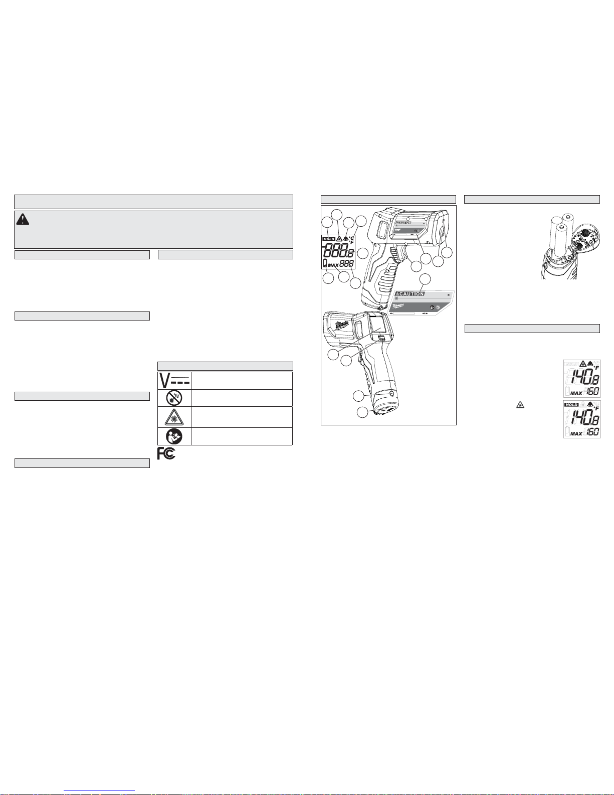
1. Laser window
2. Infrared sensor
3. Nameplate
4. Trigger
5. Display
6. Alarm Button
7. Battery door
8. Battery door lock
9. Hold indicator
10.Laser active indicator
11.Alarm indicator
12. C° or F° indicator
13.Primary
measurement
14.Secondary
measurement
15. Max reading indicator
16. Low battery indicator
3
Volts Direct Current
CAUTION Laser Light - Do Not
Stare Into Beam
Laser product
Avoid Exposure: Laser Radiation Is
Emitted From This Aperture
To reduce the risk of injury, user must
read operator’s manual.
3
ASSEMBLY
Loading/Changing the Batteries
1. Press in the battery door
lock and open the battery
door.
2. Before installing batteries
for the fi rst time, remove
the white, rectangular tag
in the battery compartment.
3. Insert three (3) AA batteries, as displayed.
4. Close the battery door
securely.
Selecting Celsius or Fahrenheit
Switch between Celsius and Fahrenheit temperature display anytime by using the switch inside the
battery compartment.
OPERATION
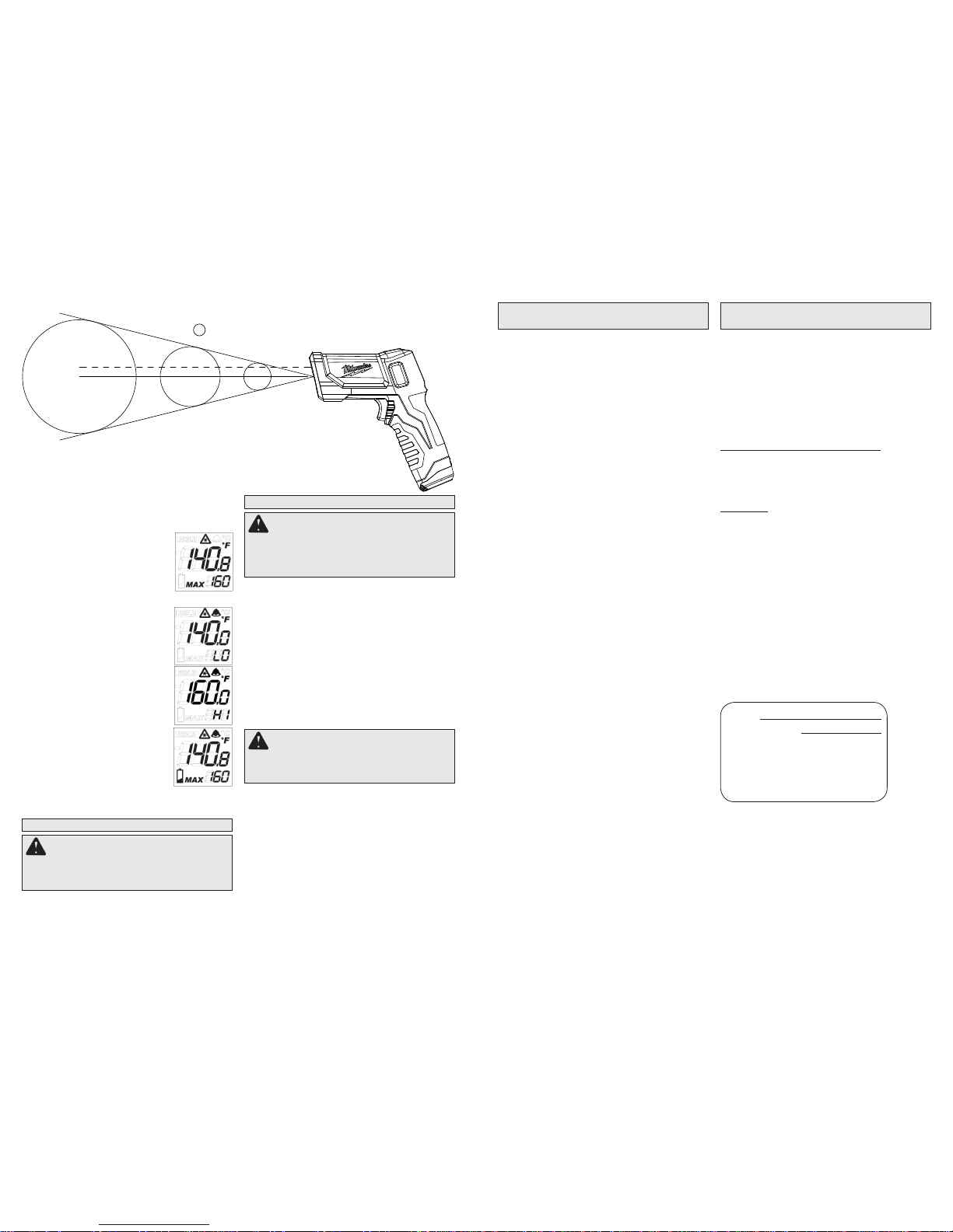
Scanning Object IR Temperature
1. Pull and hold the trigger for at least 2 seconds
and scan the surface temperature of an object.
A laser pointer is used for aiming on the area
being scanned.
NOTE: The object should be larg-
er than the spot being scanned. If
not, readings will be affected. See
Distance To Spot for necessary
object size.
2. As you continue to hold the
trigger, the icon is displayed
along with the surface temperature (primary measurement) and
maximum temperature (secondary measurement) readings.
3. Release the trigger. HOLD is
displayed until the screen shuts
off in about seven seconds.
NOTE: A quick change in temperature (>10°F) affects the meter’s readings. Allow the meter to reach
ambient temperature before use (5 to 30 minutes,
depending on temperature change).
9
10
11
13
14
16
15
2
1
2265-20
Milwaukee Electric Tool Corp.
Brookfield, WI 53005 USA Made In China
LASER RADIATION - DO NOT STARE INTO BEAM
MAXIMUM POWER < 1mW WAVE LENGTH 630 - 670 nm
CLASS II LASER PRODUCT COMPLIES WITH 21 CFR 1040.10 AND 1040.11
AVOID EXPOSURE LASER RADIATION IS
EMITTED FROM THIS APERTURE
READ OPERATORS MANUAL
LASER TEMP GUN
THERMOMETER
TM
12
4
5
At 5' away, spot is 6" in diameter
At 3' away, spot is 3.6" in diameter
At 1' away, spot is 1½" in diameter
ACCESSORIES
For a complete listing of accessories refer to your
MILWAUKEE Electric Tool catalog or go online to
www.milwaukeetool.com. To obtain a catalog, contact your local distributor or a service center.
WARNING Always remove batteries
before changing or removing accessories.
Only use accessories specifi cally recommend-
ed for this tool. Others may be hazardous.
MAINTENANCE
WARNING To reduce the risk of per-
sonal injury and damage, never immerse
your tool in liquid or allow a liquid to fl ow
inside it.
WARNING To reduce the risk of injury,
always remove the batteries from the tool
before performing any maintenance. Never
disassemble the tool. Contact a MILWAUKEE
service facility for ALL repairs.
Cleaning
Clean dust and debris from tool. Keep tool handles
clean, dry and free of oil or grease. Use only mild
soap and a damp cloth to clean the tool since certain
cleaning agents and solvents are harmful to plastics
and other insulated parts. Some of these include
gasoline, turpentine, lacquer thinner, paint thinner,
chlorinated cleaning solvents, ammonia and household detergents containing ammonia. Never use
fl ammable or combustible solvents around tools.
Repairs
For repairs, return the tool to the nearest service
center listed on the back cover of this operator's
manual.
Maintaining Tool
Keep your tool in good repair by adopting a regular
maintenance program. After six months to one year,
depending on use, return the tool to a MILWAUKEE
service facility for repairs.
If the tool does not start or operate at full power
with new batteries, clean the contacts on the battery door. If the tool still does not work properly,
return the tool to a MILWAUKEE service facility
for repairs.
Cleaning the Lens
Blow off loose particles with clean compressed
air. Carefully wipe the suface with a cotton swab
moistened with water.
Temperature Alarm
Press the Alarm button to turn on the alarm function. The bell icon is displayed. If the temperature
reading is outside the preset range, the temperature
reading will fl ash and an alarm will sound.
Muting Alarm
Mute the alarm by pressing the
Alarm button. The bell icon will go
off. The temperature reading will
continue to fl ash as long as it is
outside the preset range.
Setting Preset Range for the Alarm
1. To set the alarm range, pull and
hold the trigger and then press the
Alarm button. Repeat to toggle
between LO and HI settings.
2. Pull the trigger to increase the
values, press the Alarm button
to decrease the values. Wait 3
seconds for the ranges to save
and exit.
Low Battery
When the Low Battery icon is displayed, change the batteries.
MILWAUKEE Test & Measurement Products (including bare tool, li-ion battery pack(s) and battery charger but excluding alkaline batteries) are warranted
to the original purchaser only to be free from defects
in material and workmanship. Subject to certain
exceptions, MILWAUKEE will repair or replace any
part on this product which, after examination, is determined by MILWAUKEE to be defective in material or
workmanship for a period of fi ve (5) years* after the
date of purchase. Return the Test & Measurement
tool and a copy of proof of purchase to the nearest
Milwaukee Electric Tool Corporation - factory Service
Center. This warranty does not apply to damage that
MILWAUKEE determines to be from repairs made or
attempted by anyone other than MILWAUKEE authorized personnel, misuse, alterations, abuse, normal
wear and tear, lack of maintenance, or accidents.
*The warranty period for the LITHIUM-ION battery
pack that ships with the Test & Measurement tool is
two (2) years from the date of purchase. *Alkaline
battery that ships with Test & Measurement tool is
separately warranted by the battery manufacturer.
*The warranty period for a NON-CONTACT VOLTAGE DETECTOR – 2201 20 is one (1) year from the
date of purchase.
Warranty Registration is not necessary to obtain the
applicable warranty on MILWAUKEE product. The
manufacturing date of the product will be used to determine the warranty period if no proof of purchase is
provided at the time warranty service is requested.
ACCEPTANCE OF THE EXCLUSIVE REP AIR AND REPLACEMENT REMEDIES DESCRIBED HEREIN IS A CONDITION
OF THE CONTRACT FOR THE PURCHASE OF EVERY
MILW AUKEE PRODUCT. IF YOU DO NOT AGREE TO THIS
CONDITION, YOU SHOULD NOT PURCHASE THE PRODUCT. IN NO EVENT SHALL MILWAUKEE BE LIABLE FOR
ANY INCIDENTAL, SPECIAL, CONSEQUENTIAL OR PUNITIVE DAMAGES, OR FOR ANY COSTS, ATTORNEY FEES,
EXPENSES, LOSSES OR DELAYS ALLEGED TO BE AS A
CONSEQUENCE OF ANY DAMAGE TO, FAILURE OF, OR
DEFECT IN ANY PRODUCT INCLUDING, BUT NOT LIMITED
TO, ANY CLAIMS FOR LOSS OF PROFITS. SOME STATES
DO NOT ALLOW THE EXCLUSION OR LIMITATION OF
INCIDENTAL OR CONSEQUENTIAL DAMAGES, SO THE
ABOVE LIMITATION OR EXCLUSION MAY NOT APPLY TO
YOU. THIS WARRANTY IS EXCLUSIVE AND IN LIEU OF ALL
OTHER EXPRESS WARRANTIES, WRITTEN OR ORAL. TO
THE EXTENT PERMITTED BY LAW, MILWAUKEE DISCLAIMS
ANY IMPLIED WARRANTIES, INCLUDING WITHOUT LIMIT ATION ANY IMPLIED WARRANTY OF MERCHANTABILITY
OR FITNESS FOR A PARTICULAR USE OR PURPOSE; TO
THE EXTENT SUCH DISCLAIMER IS NOT PERMITTED BY
LAW, SUCH IMPLIED WARRANTIES ARE LIMITED TO THE
DURATION OF THE APPLICABLE EXPRESS WARRANTY AS
DESCRIBED ABOVE. SOME STATES DO NOT ALLOW LIMITATIONS ON HOW LONG AN IMPLIED WARRANTY LASTS,
SO THE ABOVE LIMITA TION MAY NOT APPL Y TO YOU, THIS
WARRANTY GIVES YOU SPECIFIC LEGAL RIGHTS, AND
YOU MAY ALSO HA VE OTHER RIGHTS WHICH V ARY FROM
STA TE TO STATE.
This warranty applies to product sold in the U.S.A. and Canada
only.
TECHTRONIC INDUSTRIES' warranty is for 5 year since the
original purchase date.
This warranty card covers any defect in material and workmanship on this Power Tool.
To make this warranty valid, present this warranty card,
sealed/stamped by the distributor or store where you purchased the product, to the Authorized Service Center (ASC).
Or, if this card has not been sealed/stamped, present the
original proof of purchase to the ASC.
Call toll-free 1 800 832 1949 to fi nd the nearest ASC, for ser-
vice, parts, accessories or components.
Procedure to make this warranty valid
Take the product to the ASC, along with the warranty card
sealed/stamped by the distributor or store where you purchased the product, and there any faulty piece or component
will be replaced without cost for you. We will cover all freight
costs relative with this warranty process.
Exceptions
This warranty is not valid in the following situations:
a) When the product is used in a different manners from the
end-user guide or instruction manual.
b) When the conditions of use are not normal.
c) When the product was modifi ed or repaired by people not
authorized by TECHTRONIC INDUSTRIES.
Note: If cord set is damaged, it should be replaced by an
Authorized Service Center to avoid electric risks.
SERVICE AND ATTENTION CENTER
Rafael Buelna No.1.
Col. Tezozomoc Mexico, Azcapotzalco D.F.
Ph. 01 800 832 1949
IMPORTED AND COMMERCIALIZED BY:
TECHTRONIC INDUSTRIES MEXICO, .S.A.
DE C.V.
Av. Santa Fe 481 piso 6, Col. Curz Manca.
CP 05349, Cuajimalpa, D.F.
LIMITED WARRANTY - MEXICO,
CENTRAL AMERICA AND CARIBBEAN
Model:
Date of Purchase:
Distributor or Store Stamp:
LIMITED WARRANTY -
USA AND CANADA
Distance to Spot 10:1
—— Center of Spot
– – – Laser pointer (approx. 3/4" above center of spot)
Spot size at distance indicated
 Loading...