

Milwaukee 2258-20 Operator's Manual
Cat. No. / No de cat.
2258-20
M12™ 102
x 77 INFRARED CAMERA
CAMÉRA À INFRAROUGE DE 102 x 77 M12™
CÁMARA INFRARROJA M12™ 102 x 77
OPERATOR'S MANUAL
MANUEL de L'UTILISATEUR
MANUAL del OPERADOR
WARNING To reduce the risk of injury, user must read and understand operator's manual.
AVERTISSEMENT An de réduire le risque de blessures, l'utilisateur doit lire et bien
comprendre le manuel.
ADVERTENCIA Para reducir el riesgo de lesiones, el usuario debe leer y entender el manual.
2
GENERAL POWER TOOL
SAFETY WARNINGS
WARNING
Read all safety warnings and in-
structions. Failure to follow the
warnings and instructions may result in electric
shock, re and/or serious injury. Save these instructions - This OPERATOR’S MANUAL contains
important safety and operating instructions for
this Infrared Camera. Before using the Infrared
Camera, read this OPERATOR’S MANUAL, the
M12TM Battery Charger and Battery OPERATOR’S
MANUAL, and all labels on the battery pack,
charger and Infrared Camera.
•
Avoid dangerous environments. Do not use in
rain, snow, damp or wet locations. Do not use in
the presence of explosive atmospheres (gaseous
fumes, dust or ammable materials) because sparks
may be generated when inserting or removing battery pack, possibly causing re or explosion.
BATTERY USE AND CARE
•Recharge only with the charger specied by the
manufacturer. A charger that is suitable for one type
of battery pack may create a risk of re when used
with another battery pack.
•Use power tools only with specically desig-
nated battery packs. Use of any other battery
packs may create a risk of injury and re.
•When battery pack is not in use, keep it away
from other metal objects like paper clips, coins,
keys, nails, screws, or other small metal objects
that can make a connection from one terminal
to another. Shorting the battery terminals together
may cause burns or a re.
SERVICE
•Have your Infrared Camera serviced by a qualied
repair person using only identical replacement
parts. This will ensure that the safety of the tool is
maintained.
•Do not disassemble. Incorrect reassembly may
result in the risk of electric shock or re. If it is dam
-
aged, take it to a MILWAUKEE service facility.
•Store in a cool, dry place. Do not store where
temperatures may exceed 120 °F (50 °C) such as
in direct sunlight, a vehicle or metal building during
the summer.
•Do not remove or deface labels. Maintain labels
and nameplates. These carry important information.
If unreadable or missing, contact a MILWAUKEE
service facility for a free replacement.
Federal Communications Commission
WARNING
Changes or modications to this unit
not expressly approved by the party
responsible for compliance could void the user’s
authority to operate the equipment. This equipment
has been tested and found to comply with the limits
for a Class B digital device, pursuant to Part 15 of
the FCC Rules. These limits are designed to provide
reasonable protection against harmful interference
in a residential installation. This equipment generates, uses and can radiate radio frequency energy
and, if not installed and used in accordance with the
instructions, may cause harmful interference to radio
communications. However, there is no guarantee
that interference will not occur in a particular installation. If this equipment does cause harmful interfer-
ence to radio or television reception, which can be
determined by turning the equipment off and on, the
user is encouraged to try to correct the interference
by one or more of the following measures:
•Reorient or relocate the receiving antenna.
•Increase the separation between the equipment
and receiver.
•Connect the equipment into an outlet on a circuit
different from that to which the receiver is connected.
•Consult the dealer or an experienced radio/TV
technician for help.
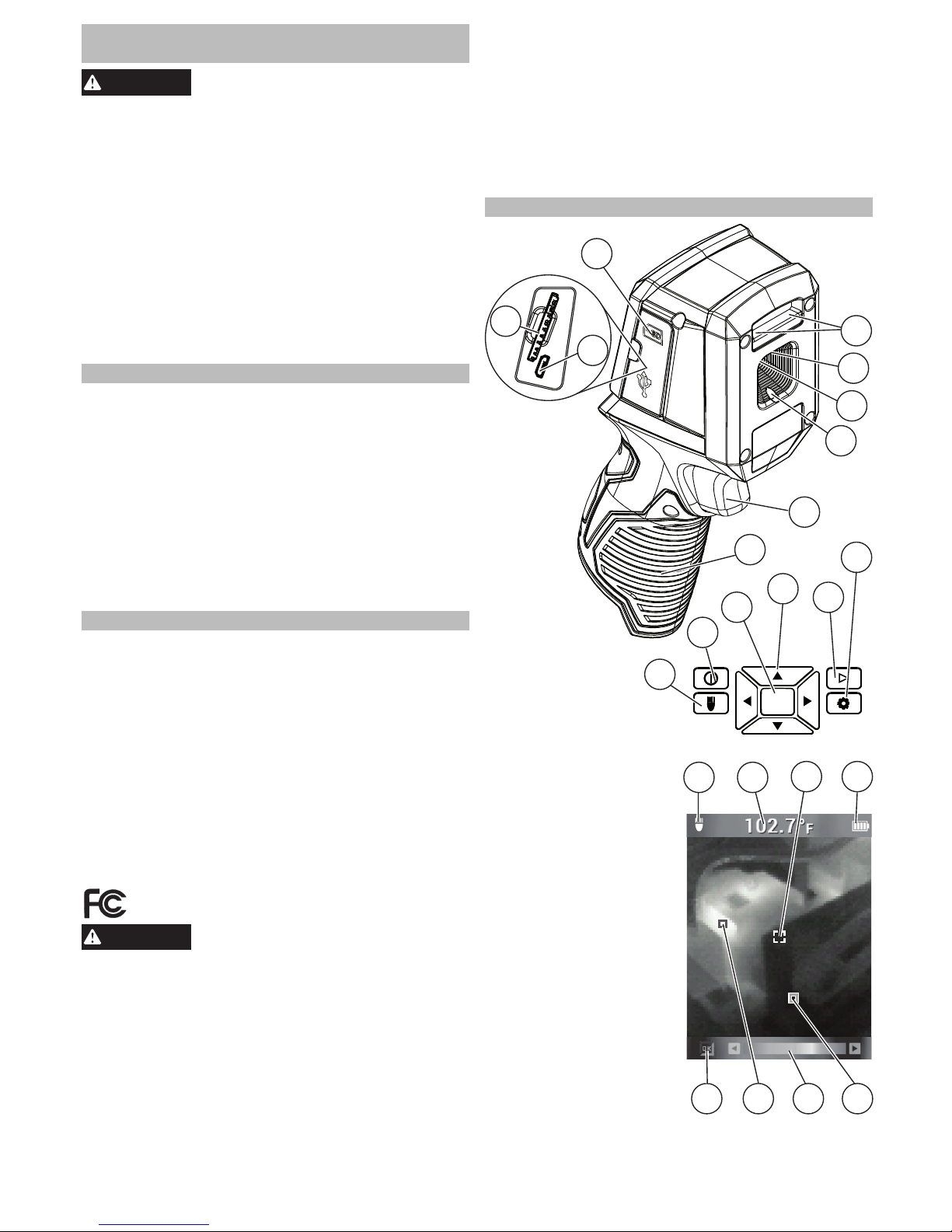
FUNCTIONAL DESCRIPTION
1. SDHC card slot
2. Micro USB port
3. Media door
4. LED worklight
5. Laser indicators
6. Infrared camera lens
7. Trigger
8. Handle
9. Settings button
10. Image review
button
11. Arrow buttons
12. OK button
13. Power button
14. LED worklight
button
15. LED worklight ON
16. Target temperature
17. Temperature
crosshair
18. Battery charge
indicator
19. COLD indicator
(blue)
20. Palette bar
21. HOT indicator (red)
22. HOT/COLD indicators ON/OFF
23. Protective cover (not shown)
OK
8
7
10
11
9
4
3
2
1
12
13
14
22 20
1817
1615
21 19
6
5
5
3
SYMBOLOGY
Read operator's manual
CAUTION
Laser Light -
Do Not Stare Into Beam
WARNING
Laser product
Avoid Exposure: Laser
Radiation Is Emitted From This Aperture
European Conformity Mark
SPECIFICATIONS
Cat. No. ..................................................... 2258-20
Volts .............................................................. 12 DC
Battery Type .................................................M12™
Charger Type ................................................M12™
Temperature Measurement
Infrared (IR) Resolution ...................102 x 77 pixels
(Picture Elements or Data Points)
Object Temperature Range 2 ............14°F to 626°F
(-10°C to 330°C)
Thermal Sensitivity ..................... 0.1°C/25°C NETD
(Noise Equivalent Temperature Difference)
Spatial Resolution............................3.0 mrad IFOV
(Instantaneous Field of View)
Accuracy ................................ ±5°C or 5% @ 25°C,
whichever is greater
On-board Adjustable Emissivity ......... Variable from
0.10 to 1.00, in increments of 0.01
Infrared (IR) Detector Type ....................... Uncooled
microbolometer focal-plane array (FPA)
Spectral Range ................................... 7.5 to 14 μm
Thermal Imaging
Field of View (FOV) ......26.8° (Horiz.) X 35.4°(Vert)
Focus Method ...................................... Fixed Focus
Minimum Distance in Focus .............36" (91.4 mm)
Screen Refresh................................................ 8 Hz
Physical and Environmental
Drop Test .........................6' (2 m) Drop to concrete
Operating Temperature Range ..........14°F to 122°F
(-10°C to 50°C)
Operating Storage Humidity Range......... 10%-90%
Non-condensing
Laser
Maximum Power ...........................................<1mW
Wave Length ........................................ 630-670nm
Class......................................................................II
Laser Complies with ..... 21CFR 1040.10 & 1040.11
General
Image Storage Included ....Removable 8GB SDHC
Tested to accept an SDHC card up to 32GB.
Data Communication Interface .............. Micro USB
Display ..........................Color TFT-LCD 2.4" (6 cm)
measured diagonally
NOTE: Displayed readings < -10°C and > 330°C
are not specified. The LED floodlight does not affect
thermal images.
INITIAL START-UP
The rst time the Infrared Camera is turned on, you
are required to select the Language, Time, and Date.
See Personal Settings for more information.
SET-UP
WARNING
Recharge only with the charger
specied for the battery. For specic charging instructions, read the operator’s
manual supplied with your charger and battery.
Inserting/Removing the Battery
To remove the battery, push in the release buttons
and pull the battery pack away from the tool.
To insert the battery, slide the pack into the body
of the tool. Make sure it latches securely into place.
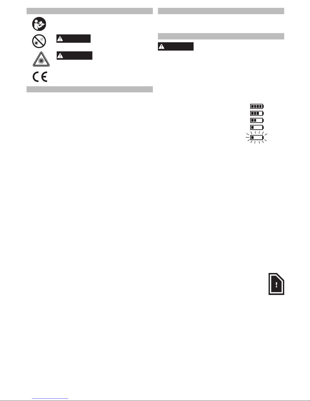
Battery life
A fuel gauge on the Infrared Camera
25%
50%
75%
100%
<10%
display shows the remaining battery
charge. At approximately 10% remaining charge, the fuel gauge will
begin to blink red. When no charge
remains, a Low-Battery Message
appears on the display for 3 sec-
onds before the Infrared Camera
shuts down.
Power-Saving Features
To preserve battery life, the Infrared Camera goes
into Sleep Mode after 5 minutes of no activity. Sleep
Mode maintains a ready-to-go, warmed-up condition,
but uses little battery power. To reactivate the tool,
pull the trigger or press any button. After another
15 minutes of no activity, the Infrared Camera turns
itself completely off. Press the power button to turn
the tool back on.
Removing/Installing the SDHC Memory Card
Install the SDHC card before use. The Infrared Camera does not store any images without one installed.
To install or remove:
1. Turn off the tool.
2. Open the rubber media door.
3. To remove, press in and release. The SDHC card
will pop out. Pull out the card.
4. To install, slide the SDHC card into the slot and
press in rmly. The label on the SDHC card should
face the display of the Infrared Camera.
5. Close the media door.
NOTE: A display notication will alert you
when the SDHC card is missing, almost full,
and again when it is full. Delete or transfer
images to another device to free up space on
the SDHC card, or use another SDHC card.
4
Selecting the Color Palette
Select one of three color palettes to suit your needs.
Turn the tool on, then use the arrow ◄► buttons to
step through the palettes.
RAINBOW Shows a very wide range of
temperatures
IRON-BOW Useful for revealing small
temperature differences
HIGH CONTRAST Shows the most detail
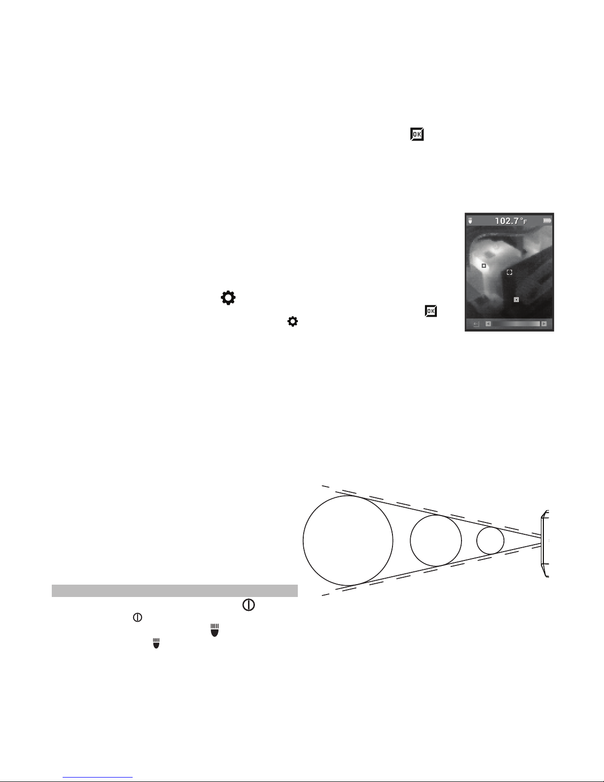
HOT/COLD Indicator marks
To turn the HOT/COLD Indicator marks on or off
while taking a temperature measurement, press
the OK button during live view. Red (hot) and blue
(cold) target marks locate the highest and lowest
temperatures in the display area.
Taking a Temperature Measurement
1. Insert a battery pack and turn
on the tool.
2. Point the tool at the target.
The Target Temperature is displayed at the top of the screen.
3. To activate the laser guides,
pull the trigger softly (less than
half-way). See "83:1 Distance
to Spot Ratio".
4. Turn the HOT/COLD
indi-
cator marks on or off, or toggle
through the different palettes
to get the desired image on the display.
5. The center temperature is affected by the material
of the target, and can be adjusted by changing the
Emissivity. See "Selecting the Emissivity".
Using the Laser Indicators
Use the lasers to frame up the target area. The
lasers correlate to the temperature crosshair on the
display. Lasers are accurate to 3" @ 50'. The target
temperature is taken in between the laser indicators,
and sized according to the following chart.
83:1 Distance to Spot Ratio
At 83' away,
spot is ~Ø 1'
At 25' away,
spot is ~Ø 4"
At 3' away,
spot is ~Ø 1/2"
NOTE: A quick change in temperature (>10°F) can
affect the meter’s readings. Always allow the meter to reach its stable operating temperature after
startup and before use (5 to 30 minutes, depending
on environment).
Viewing Images on Another Device
Saved images can be transferred to another device in
two ways - by removing the SDHC card and inserting
it into another device, or by connecting the Infrared
Camera directly to another device. This allows the
images to be available for things like email, inserting into documents, or for use in the MILWAUKEE
Thermal Imaging Software.
To transfer the SDHC card, follow the Removing/
Installing the SDHC Memory Card instructions. To
transfer pictures directly, connect the micro USB
cord to the Infrared Camera micro USB port. Connect the other end to your device. Turn the Infrared
Camera on.
Two types of les are created for each image. A
".PNG" le is created for general use. A ".DAT" le
is created for use in the MILWAUKEE Thermal Imag-
ing Software.
MILWAUKEE Thermal Imaging Report
Software
The MILWAUKEE Thermal Imaging Report Software
is available for download from the 2258-21 product
page at www.milwaukeetool.com.
Refer to the Thermal Imaging Report software
manual PDF for training.
Personal Settings
To set up the Infrared Camera to your personal preferences, turn on the tool and press the Settings
button. Use the arrow ▲▼◄► buttons and OK button to toggle and select the desired settings.
LASER Turn the laser guides ON/OFF
CROSSHAIR Turn the crosshair ON/OFF
EMISSIVITY Select the Emissivity of the
target (see "Selecting the
Emissivity")
UNITS Select Fahrenheit (F°) or
Celsius (C°)
TIME Set the time
DATE Set the date
FORMAT Select the Time and Date
formats
LANGUAGE Select the display language
DELETE ALL Delete all images on the
SDHC card
FACTORY RESET Return Infrared Camera to
original factory settings
SYSTEM INFO Display system information
OPERATION
Turning the Tool ON/OFF
Press the Power button to turn the tool on and off.
Turning the Worklight ON/OFF
Press the Worklight button to turn the worklight
on and off.
Optimizing Thermal Images
Use the emissivity settings, palette selection, and
HOT/COLD indicators to optimize your thermal images to your needs.
5
Taking a Thermal Image
An SDHC card must be installed for the Infra-
red Camera to save images and data. If no
SDHC card is installed, the error message
"NO SD CARD" is displayed.
1. Use the steps under "Taking a Temperature Mea-
surement" section to frame the desired image on
the display.
2. The Target Temperature, color palette, and any
displayed marks will be captured in the image.
3. Pull the trigger fully to take the picture.
4. To save the image, press the OK button or pull
the trigger again.
5. To cancel the image, use the arrow ◄► buttons to
select Cancel, then press the OK button.
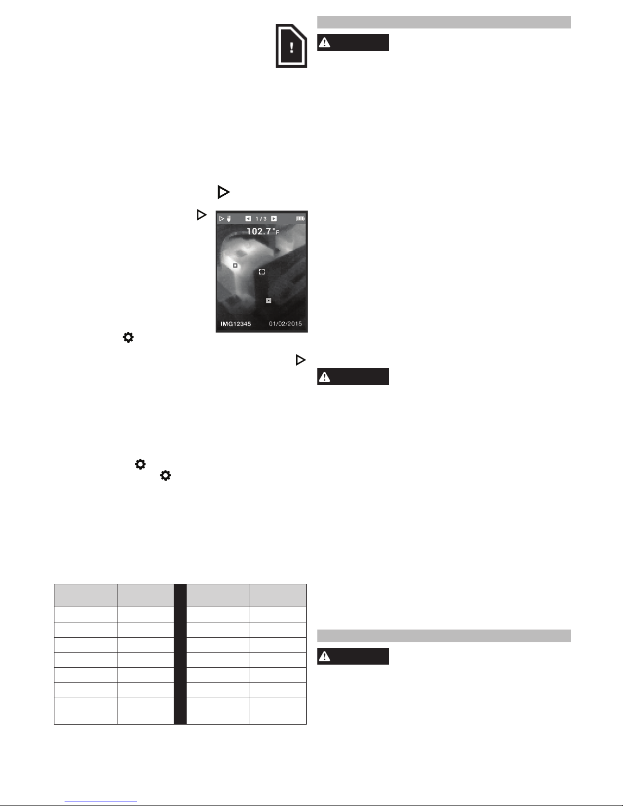
Image Review
To review the saved images on the display:
1. Press the Image Review
button.
2. Use the arrow ◄►buttons to
scroll through the images.
3. To delete an image, press
the OK button to select the
displayed image, then use the
arrow ◄► buttons to select
Delete. Press the OK button
again.
4. Use the DELETE ALL function
in Settings
to batch-delete
the images.
5. To return to live view, press the Image Review
button again.
Selecting the Emissivity
Emissivity is an internal setting that is used to adjust
the tool based on the type of material being mea-
sured. Different materials emit radiation differently
and changing the emissivity value will provide a
more accurate temperature based on the material
being measured. Select the material or emissivity
level in Settings
.
1. Press the Settings
button.
2. Use the arrow ▲▼ buttons to select EMISSIVITY.
3. Press OK.
4. Emissivity can be set by ratio or material.
Use the arrow ◄► buttons to select the ratio column or the material column. Then, use the arrow
▲▼ buttons to select the desired ratio or material.
5. Press OK.
Target Materials and Corresponding
Emissivity Ratios
Material
Emissivity
Ratio Material
Emissivity
Ratio
Aluminum * 0.30 Paint 0.93
Asphalt 0.95 Rubber 0.95
Brick 0.83 Sand 0.90
Concrete * 0.95 Soil 0.92
Copper 0.60 Steel * 0.80
Iron 0.70 Water * 0.93
Oil
(Petroleum)
0.94 Wood 0.94
*Available Material Setting in the EMISSIVITY menu.
MAINTENANCE
WARNING
To reduce the risk of injury, always
unplug the charger and remove the
battery pack from the charger or tool before
performing any maintenance. Never disassemble
the tool, battery pack or charger. Contact a
MILWAUKEE service facility for ALL repairs.
Obtaining Technical Support or Service
Your tool should not need calibration, however, to
obtain documentation that your tool meets specica-
tions, contact the nearest service center. The tool will
be sent out for testing, and you will receive it back
with proper documentation.
Maintaining Tool
Keep your tool, battery pack and charger in good repair by adopting a regular maintenance program. Af-
ter six months to one year, depending on use, return
the tool, battery pack and charger to a MILWAUKEE
service facility for:
• Lubrication
• Mechanical inspection and cleaning (gears, spin-
dles, bearings, housing, etc.)
• Electrical inspection (battery pack, charger, motor)
• Testing to assure proper mechanical and electrical
operation
If the tool does not start or operate at full power with
a fully charged battery pack, clean the contacts on
the battery pack. If the tool still does not work properly, return the tool, charger and battery pack, to a
MILWAUKEE service facility for repairs.
WARNING
To reduce the risk of personal in-
jury and damage, never immerse
your tool, battery pack or charger in liquid or
allow a liquid to ow inside them.
Cleaning
Clean dust and debris from vents. Keep handles
clean, dry and free of oil or grease. Use only mild
soap and a damp cloth to clean, since certain cleaning agents and solvents are harmful to plastics and
other insulated parts. Some of these include gasoline,
turpentine, lacquer thinner, paint thinner, chlorinated
cleaning solvents, ammonia and household deter-
gents containing ammonia. Never use ammable or
combustible solvents around tools.
Cleaning the Lens
Blow off loose particles with clean compressed
air. Carefully wipe the surface with a cotton swab
moistened with water. Using a second cotton swab,
dry completely.
Repairs
For repairs, return the tool, battery pack and charger
to the nearest service center.
ACCESSORIES
WARNING
Use only recommended accesso-
ries. Others may be hazardous.
For a complete listing of accessories, go online to
www.milwaukeetool.com or contact a distributor.
 Loading...