

OPERATOR'S MANUAL
MANUEL de L'UTILISATEUR
MANUAL del OPERADOR
Cat. No. / No de cat.
2236-20, 2237-20
CLAMP METERS
PINCE AFFICHEUR DE COURANT
MEDIDORES DE PINZA
WARNING To reduce the risk of injury, user must read and understand operator's manual.
AVERTISSEMENT An de réduire le risque de blessures, l'utilisateur doit lire et bien
comprendre le manuel.
ADVERTENCIA Para reducir el riesgo de lesiones, el usuario debe leer y entender el manual.

WARNING
WARNING
IMPORTANT
SAFETY
INSTRUCTIONS
READ ALL SAFETY WARNINGS AND INSTRUCTIONS.
Failure to follow the warnings and instructions
may result in electric shock, re and/or serious
injury, as well as instrument damage and/or dam-
age to the equipment being tested.
Save these instructions - This operator’s manual
contains important safety and operating instructions for the MILWAUKEE Clamp Meters. Before
using, read this operator’s manual and all labels
on the Clamp Meters.
DANGER
Never make measurement on a circuit in which
voltage over AC600V exists. Use only leads rated
600V or better.
Do not attempt to make measurement in the pres-
ence of ammable gasses. Otherwise, the use of
the instrument may cause sparking, which can
lead to an explosion.
Transformer jaw tips are designed not to short the cir-
cuit under test. If equipment under test has exposed
conductive parts, however, extra precaution should
be taken to minimize the possibility of shorting.
Never attempt to use the instrument if its surface
or your hand is wet.
Do not exceed the maximum allowable input of
any measuring range.
Only test on unenergized circuits unless abso-
lutely necessary.
Check tool functionality on a known circuit rst.
Never assume tool is working. Assume circuits are
live until they can be proven de-energized.
Do not ground yourself while measuring. Avoid
body contact with earthed or grounded surfaces
such as pipes, radiators, ranges and refrigerators.
Never open the Battery cover during a measurement.
The instrument is to be used only in its intended
applications or conditions. Otherwise, safety func-
tions equipped with the instrument doesn’t work,
and instrument damage or serious personal injury
may be caused.
To reduce the risk of injury from shock and arc
blasts, always wear personal protective equipment
where live conductors are exposed.
Never attempt to make measurement if any abnormal conditions, such as broken case and exposed
metal parts are found on the instrument.
Do not rotate the Rotary Dial while the test leads
are being connected.
Verify proper operation on a known source before
use or taking action as a result of the indication
of the instrument.
Do not install substitute parts or make any modication to the instrument. For repair or re-calibration, return the tool to a factory Service/Sales
Support Branch or authorized service station.
Do not try to replace the batteries if the surface of
the instrument is wet.
Disconnect all the cords and cables from the object
under test and power off the instrument before
opening the Battery Cover for Battery replacement.
This tool is designed to be powered by 2-AA batter-
ies properly inserted into the MILWAUKEE Clamp
Meters. Do not attempt to use with any other voltage or power supply.
Install battery according to polarity (+ and –) diagrams.
Do not leave batteries within the reach of children.
Do not mix new and used batteries. Do not mix
brands (or types within brands) of batteries.
Properly dispose of used batteries.
Do not incinerate or dismantle batteries.
Under abusive conditions, liquid may be ejected
from the battery, avoid contact. If contact accidentally occurs, ush with water. If liquid contacts
eyes, additionally seek medical help. Liquid ejected from the battery may cause irritation or burns.
CAUTION
Set the Rotary Dial to an appropriate position
before starting measurement.
Firmly insert the test leads.
Disconnect the test leads from the instrument for
current measurement.
Do not expose the instrument to the direct sun,
high temperature and humidity or dew fall.
Altitude 2000m or less. Appropriate operating
temperature is within -10ºC and 50ºC.
This instrument isn’t dust & water proofed. Keep
away from dust and water.
Be sure to power off the instrument after use. When
the instrument will not be in use for a long period,
place it in storage after removing the batteries.
Use a cloth dipped in water or neutral detergent
for cleaning the instrument. Do not use abrasives
or solvents.
GENERAL SPECIFICATIONS
Cat. No. ...................................... 2236-20, 2237-20
Accuracy is specied for 1 year after calibration, at
operating temperatures of 64°F to 82°F (18°C to
28°C), with relative humidity at 0 % to 85 %.
Maximum voltage between any
terminal and earth ground ...................... 600 V
Jaw Opening .......................approx. 1.3" (33 mm)
(maximum conductor size)
Temperature
Operating .............14°F to 122°F (-10°C to 50°C)
Storage .............. -40°F to 140°F (-40°C to 60°C)
Temperature Coefcient ...............................0.1 x
Operating Altitude ............................2,000 meters
Drop Test ................................................... 1 Meter
Battery ........................ 2 AA, NEDA 15 A,IEC LR6
Battery Life ..............Approx. 30 Hours all lights on
Safety Compliances .......UL/CSA 61010-1 3rd Ed
UL/CSA 61010-2-032 1st Edition (Clamp Assemblies)
Certications............................................... cULus
2
(specied accuracy)/°C (<18°C or >28°C)
UL/CSA/IEC/EN 61010-031 1st Ed + A1 (Probes)
UL/CSA 61010-2-033 1st Ed (Meters)
Measurement Category III, 600V
Pollution Degree 2, EMC EN61326-1
C
US
FUNCTIONS
Dial Position Range Resolution Accuracy
Voltage DC 60/600V 0.01V/0.1V ±1.0%rdg±3dgt
Voltage AC 0.0 to 600.0V 0.1V
0 to 600.0A
Current AC
Current DC
(2237-20)
Resistance 600Ω/6kΩ 0.1Ω/0.001kΩ ±1.0%rdg±5dgt
Capacitance
Continuity
uA Current
DC uA (2236-20)
Temperature
(2236-20)
Hertz (2237-20)
Hz
* These instruments are True-RMS sensing. All voltage and current readings are True-RMS values.
SYMBOLOGY
Peak 1500A
CF=2.5@600A
CF=3.0@500A
0.1A
0-600.0A 0.1A ±1.5%rdg±5dgt
0.01nF - 4000μF
Auto-ranging
Cont Buzzer
0-600.0Ω
0.01nF/0.1nF/
0.001μF/0.01μF/
0.1μF/1μF
0-600.0uA 0.1uA ±1.5%rdg±5dgt
-40C - 400C
-40F - 32.0F
32.1F - 752F
ACA: 40-400Hz,
ACV: 1Hz-10kHz
0.1C
0.1F
0.001/0.01/0.1Hz
0.001/0.01kHz
FUNCTIONAL DESCRIPTION
±1.5%rdg±4dgt (50/60Hz)
±3.5%rdg±5dgt (40~400Hz)
±2.0%rdg±5dgt(50/60Hz)
±3.5%rdg±5dgt(40 ~ 400Hz)
* Add 2% at CF>2
* < 5A, add 3dgt
0.01nF-39.99nF ±2.5%±2nF
40.00nF-1000uF ±2.5%±20dgt
1000uF> ±5%±20dgt
Buzzer sounds at 35Ω ±10Ω or 25Ω or
-40.0F to 20.0F; ±1.5%F ±4F
20.1F to 752F; ±1.5%F ±2F
ACA: 40-400Hz ±0.5%rdg±5dgt
ACV:1Hz-10kHz ±0.5%rdg±5dgt
* Minimum Measurable inputs are: 70
Vrms for VAC or 50 Arms for ACA
less
±1.0%C ±2.0C
Read Operator's Manual
Double insulation
Risk of electric shock
Indicates that this instrument can clamp
on bare conductors when measuring a
voltage corresponding to the applicable
measurement category, which is
marked next to this symbol.
Earth (Ground)
Danger, Warning, or Caution Consult the operator's manual for
additional safety information.
Battery compartment
Do not dispose of this product as
unsorted municipal waste.
UL Listing for Canada and U.S
Cat III
Classication of transient overvoltages,
based on nominal line voltage to earth.
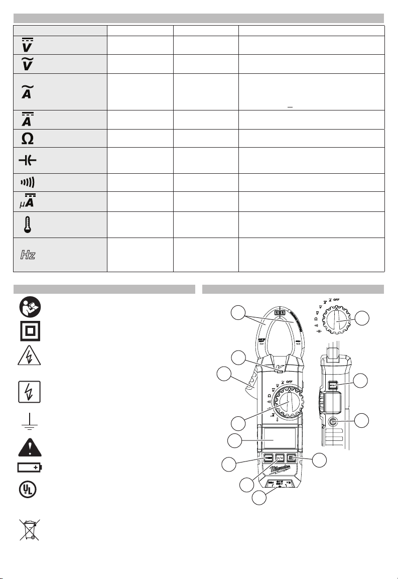
1
Cat. No.
2236-20
2
3
4
5
6
7
8
1. Current sensing jaws
2. NCVD indicator
3. Jaw opening trigger
4. Rotary Dial
5. Display
6. Zero button
3
4
Cat. No.
2237-20
11
10
9
7. °F/°C button (2236-20)
Hz button (2237-20)
8. Terminal inputs
9. Min/Max button
10. Worklight LED
11. Hold button

DANGER
DANGER
ASSEMBLY
WARNING
WARNING
DANGER
To avoid an electrical hazard, turn
nect the test leads before replacing batteries.
Loading/Changing the Batteries
Replace batteries when the Low Battery indicator
is displayed.
1. Turn Rotary Dial to OFF and
disconnect the test leads.
2. Unscrew and remove battery door.
3. Insert two (2) AA batteries,
according to the polarity
marked in the battery compartment
4. Close the battery door and
tighten screw securely.
the Rotary Dial to OFF and discon-
OPERATION
Only use MILWAUKEE test leads
Inspect test leads before each use. Use clamp
meter to run a continuity test.
Conrm the Rotary Dial is set to the correct position, the instrument is set to the correct measurement mode, and the Data hold function is disabled.
Otherwise, desired measurement cannot be made.
The LCD backlight will turn off after about 3 minutes
of inactivity. Push any button or turn the rotary dial
to turn the backlight on.
cuit in which voltage over AC600V exists. Clamp
tips are designed not to short the circuit under
test. If equipment under test has exposed conductive parts, however, extra precaution should
be taken to minimize the possibility of shorting.
Do not use with the Battery Cover removed.
Disconnect the test leads from the instrument for
current measurement.
1. Set the Rotary Dial to position.
AC mark is displayed.
2. Press the jaw opening trigger to
open the jaws and clamp them onto
the conductor under test. The reading is displayed.
Cat. No. 2237-20 only: Pressing
the “Hz” Key toggles the reading
between AC Current and Hz.
NOTE: Hz Function requires 50A or
more.
NOTE: Do not clamp over 2 or more
wires at the same time. Irregular
results will occur.
CAUTION
ment, keep the jaws fully closed to ensure accurate measurements.
with the MILWAUKEE Clamp Meters.
Before Use
LCD Backlight
Making a Measurement
AC Current
To avoid electrical shock:
Never make measurement on a cir-
Maximum conductor size is about
1.3" diameter. During measure-
DC Current
(Cat. No. 2237-20 only)
To avoid electrical shock:
circuit in which voltage over AC600V exists.
Do not use with the Battery Cover removed.
1. Set the Rotary Dial to position.
DC mark is displayed.
2. With the jaws closed and without
clamping them around a conductor,
press the ZERO key to zero adjust
the display.
3. Press the jaw opening trigger to
open the jaws and clamp them
around the conductor under test.
The reading is displayed.
NOTE: Do not clamp over 2 or more
wires at the same time. Irregular
results will occur.
4. Set the Rotary Dial to an appropriate position according to current under test.
5. Press the ZERO key again to release the ZERO
function.
CAUTION
meter, the polarity is positive; ow from underside to display side, the polarity is negative.
Never make measurement on a
When current ows from the display side to the underside of the
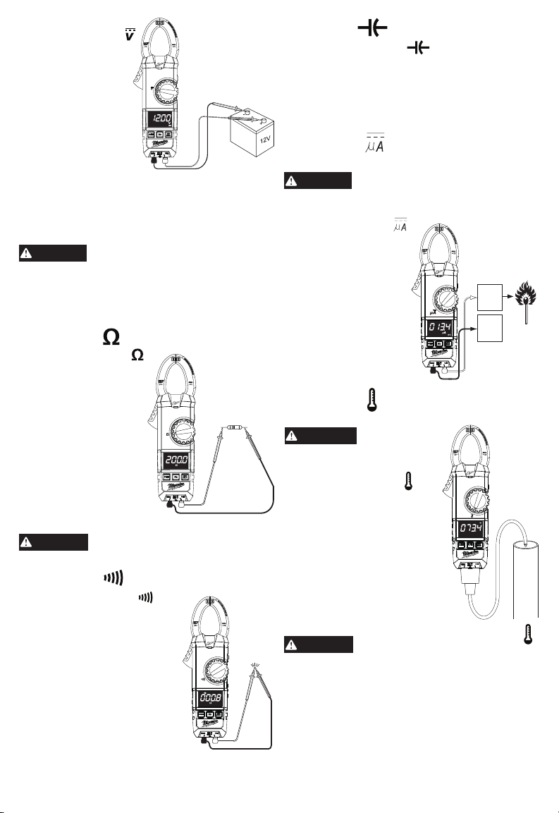
AC Voltage
To avoid electrical shock:
circuit in which voltage over AC600V exists.
Do not use with the Battery Cover removed.
Keep ngers away from jaws during measure-
ments.
1. Set the Rotary Dial to
tion.
2. Connect the red test lead to
the VΩ terminal and the black
test lead to the COM terminal.
3. Connect the test leads to the
circuit under test. The reading
is displayed.
Cat. No. 2237-20 only: Press-
ing the Hz Key toggles the
reading between AC Voltage
and Hz. NOTE: Hz Function
requires 70V or more.
CAUTION
ronments.
Never make measurement on a
posi-
AC
Readings of frequency may uctuate or be inuenced in noisy envi-
DC Voltage
DANGER
circuit in which voltage over DC600V exists.
Do not use with the Battery Cover removed.
Keep ngers away from jaws during measure-
ments.
To avoid electrical shock:
Never make measurement on a
4
1.
WARNING
Set the Rotary Dial to
position.
2. Connect the red test
lead to the VΩ terminal and the black
test lead to the COM
terminal.
3. Connect the red test
lead to the positive
(+) side and black
test leads to the
negative (-) side
of the circuit under
test. The reading is displayed. A reversed connection is indicated as a negative value.
Resistance/Continuity/Capacitance
Measurements
DANGER
Capacitance measurements, never use the meter
on an energized circuit. Make sure a capacitor is
fully discharged before touching or attempting
to make a measurement.
Do not use with the Battery Cover removed.
To reduce the risk of electric shock
for Resistance, Continuity, and
Resistance
1. Set the Rotary Dial to
position.
2. Connect the red test
lead to the VΩ terminal
and the black test lead
to the COM terminal.
Confirm “OL” is indi-
cated on the display,
and then short-circuit
the tips of test leads
to make the indication
zero.
3. Connect the test leads
to both ends of the
resistor under test.
4. The reading is displayed.
CAUTION
After shorting the test leads, the
displayed value may not be zero
due to the resistance of test leads themselves.
Continuity
1. Set the Rotary Dial to position.
2. Connect the red test lead to the
VΩ terminal and the black test
lead to the COM terminal.
Conrm “OL” is indicated on
the display, and then shortcircuit the tips of test leads to
make the indication zero. A
buzzer will sound.
3. Connect the test leads to both
ends of the conductor under
test. If the resistance under
test is 35 ±10Ω or 25Ω or less,
the buzzer will sound.
Capacitance
1. Set the Rotary Dial to position.
2. Connect the red test lead to the VΩ terminal and
the black test lead to the COM terminal.
3. Discharge capacitor.
4. Connect the test leads to both ends of the capacitor under test.
5. The reading is displayed.
DC Current
(Cat. No. 2236-20 only)
DANGER
circuit in which voltage over AC600V exists.
Do not use with the Battery Cover removed.
1. Set the Rotary Dial to
position. DC mark is
displayed.
2. Connect the red test
lead to the VΩ terminal
and the black test lead
to the COM terminal.
Contact the red test
lead to the ame sensor probe and the black
test lead to the control
module.
3. Turn on the heating
unit. The reading is
displayed.
ture Probe to an energized
circuit.
1. Set the Rotary Dial to
tion.
2. Connect the K-type Temperature Probe to the input
terminal. The positive (+) side
of Probe should be connected
to VΩ.
3. Place the probe sensor in the
desired location.
4. The reading is displayed.
CAUTION
displayed. If anything else is displayed, some-
thing may be wrong with the meter. Stop using
the meter immediately.
To avoid electrical shock:
Never make measurement on a
Flame
sensor
probe
Control
Module
Temperature
(Cat. No. 2236-20 only)
Never connect
the Tempera-
posi-
When the Rotary Dial is set to ,
the room temperature should be
5

Worklight LED ON/OFF
WARNING
WARNING
To turn the light on and off, press the button.
HOLD Key
Data Hold Function - Freezes the value on the display. Press the “HOLD” button to freeze the reading.
The reading will be held regardless of subsequent
variation in input. HOLD is displayed with the reading. To exit Data Hold mode, press the HOLD button
again.
CAUTION
Mode.
The clamp meter is automatically powered off in
about 20 min after the last Rotary Dial or button
operation. To reset, rotate the Rotary Dial to OFF.
If the display is still blank when a new Rotary Dial
setting is selected, replace the batteries.
The sleep mode is disabled when the MIN/MAX
function is selected.
The clamp meter does use battery power in sleep
mode. Be sure to switch the tool to OFF to conserve
battery power.
The Data Hold readings are re-
leased when the meter enters Sleep
Sleep Mode
Non-Contact Voltage Detection (NCVD)
DANGER
cal circuit or equipment. Never touch the circuit
under test to avoid possible danger even if the
LED for NCVD is not displayed.
Check the functionality of LED on a well-known
power supply prior to measurement. When the LED doesn’t
light up, do not make measurement.
NCVD indication is affected by
external voltage, and how the
meter is held or placed.
When the meter is on in any
function, the non-contact voltage detector will indicate with a
Red LED on the display when
an electric eld exceeding 90V is
detected. Place the edge of the
jaw labeled “Voltage Detector”
near the electric eld.
The LED may not be displayed due
to installation condition of electri-
Over-ow indication
Any time the input exceeds the measuring range “OL”
or “-OL” is displayed.
CAUTION
MAX button after an appropriate range is selected by Auto-ranging function. ZERO and Hz
keys are disabled while MIN/MAX Function is
active.
Clamp the jaws around the conductor under test and press the MIN/
The MIN/MAX function can be used
during measurements of AC or DC
current, AC or DC voltage, Temperature (2236-20 only), uA DC (2236-20
only), and Resistance. The MIN/MAX
function does not work in the Capacitance or Continuity measurements.
To measure the minimum or maximum
of the function, set the dial to the appropriate dial position and then press
the MIN/MAX button to capture the
maximum reading. Press the MIN/
MAX button again to capture the
minimum reading.
Press the MIN/MAX button to toggle
between minimum or maximum. The
minimum or maximum reading is
displayed and held until the MIN/MAX is turned off
by holding in the MIN/MAX button for 2 seconds or
changing the Rotary Dial position.
CAUTION
is in use. ZERO function operates only in AC
Current , DC Current and Capacitance .
AC Current / DC Current : When the LCD
doesn’t read ZERO while the
Jaws are closed, press the
ZERO Button to indicate
ZERO before starting a
measurement. In this case,
the “ZERO” mark appears
on the LCD to indicate the
ZERO Function is activated.
Capacitance : Effective
at 40nF Range only. Press
the ZERO Button with the
Test leads opened before
measuring capacitances to
indicate ZERO before starting a measurement.
MIN/MAX Function
Auto-Ranging and MIN/MAX button
are disabled when ZERO function
ZERO Function
MAINTENANCE
To reduce the risk of injury, always
before performing any maintenance. Never disassemble the tool. Contact a MILWAUKEE service
facility for ALL repairs.
Keep your tool in good repair by adopting a regular
maintenance program. After one year, it is recommended to return the tool to a MILWAUKEE service
facility for calibration.
If the tool does not start or operate at full power with
fully charged batteries, clean the contacts on the battery door. If the tool still does not work properly, return
the tool to a MILWAUKEE service facility for repair.
your tool, battery pack or charger in liquid or
allow a liquid to ow inside them.
remove the batteries from the tool
Maintaining Tool
To reduce the risk of personal injury and damage, never immerse
6
 Loading...