

Milwaukee Tool 2206-20 User Manual [en, es, fr]
Cat. No.
No de cat.
2205-20
2206-20
OPERATOR'S MANUAL
MANUEL de L'UTILISATEUR
MANUAL del OPERADOR
FORK METERS
TESTEUR ÉLECTRIQUE À MÂCHOIRES OUVERTES
COMPROBADORES DE CORRIENTE TIPO HORQUILLA
TO REDUCE THE RISK OF INJURY, USER MUST READ AND UNDERSTAND OPERATOR'S
MANUAL.
AFIN DE RÉDUIRE LE RISQUE DE BLESSURES, L'UTILISATEUR DOIT LIRE ET BIEN
COMPRENDRE LE MANUEL DE L'UTILISATEUR.
PARA REDUCIR EL RIESGO DE LESIONES, EL USUARIO DEBE LEER Y ENTENDER EL
MANUAL DEL OPERADOR.
IMPORTANT SAFETY INSTRUCTIONS
WARNING READ ALL SAFETY WARNINGS AND INSTRUCTIONS.
Failure to follow the warnings and instructions may result in electric shock, fi re and/or serious
injury, as well as instrument damage and/or damage to the equipment being tested.
Save these instructions - This operator’s manual contains important safety and operating
instructions for the MILWAUKEE Fork Meters. Before using, read this operator’s manual and
all labels on the Fork Meters.
DANGER
Never make measurement on a circuit in which voltage over AC1000V exists. Use only leads
rated 1000V or better.
Do not attempt to make measurement in the presence of fl ammable gases. Otherwise, the use
of the instrument may cause sparking, which can lead to an explosion.
Never attempt to use the instrument if its surface or your hand is wet.
Do not exceed the maximum allowable input of any measuring range.
Only test on unenergized circuits unless absolutely necessary.
Check tool functionality on a known circuit fi rst. Never assume tool is working. Assume circuits
are live until they can be proven de-energized.
Do not ground yourself while measuring. Avoid body contact with earthed or grounded sur-
faces such as pipes, radiators, ranges and refrigerators.
Never open the Battery cover during a measurement.
This instrument is to be used only in its intended applications or conditions. Otherwise, the
instrument's safety functions may not work, resulting in serious personal injury and instrument damage.
To reduce the risk of injury from shock and arc blasts, always wear personal protective
equipment where live conductors are exposed.
WARNING
Never attempt to make measurement if any abnormal conditions, such as broken case and
exposed metal parts are found on the instrument.
Do not rotate the Rotary Dial while the test leads are being connected.
Verify proper operation on a known source before use or taking action as a result of the indi-
cation of the instrument.
Do not install substitute parts or make any modifi cation to the instrument. For repair or re-
calibration, return the tool to a factory Service/Sales Support Branch or authorized service
station.
Do not try to replace the batteries if the surface of the instrument is wet.
Disconnect all the cords and cables from the object under test and power off the instrument
before opening the Battery Cover for Battery replacement.
This tool is designed to be powered by 2-AA batteries properly inserted into the MILWAUKEE
Fork Meters. Do not attempt to use with any other voltage or power supply.
Install battery according to polarity (+ and –) diagrams.
Do not leave batteries within the reach of children.
Do not mix new and used batteries. Do not mix brands (or types within brands) of batteries.
Properly dispose of used batteries.
Do not incinerate or dismantle batteries.
Under abusive conditions, liquid may be ejected from the battery, avoid contact. If contact
accidentally occurs, fl ush with water. If liquid contacts eyes, additionally seek medical help.
Liquid ejected from the battery may cause irritation or burns.
2
CAUTION
Set the Dial to an appropriate position before starting measurement.
Firmly insert the test leads.
Disconnect the test leads from the instrument for current measurement.
Do not expose the instrument to the direct sun, high temperature and humidity or dewfall.
Altitude 2000m or less. Appropriate operating temperature is within -10ºC and 50ºC.
Keep away from excess dust and water.
Be sure to power off the instrument after use. When the instrument will not be in use for a long
period, place it in storage after removing the batteries.
Use a cloth dipped in water or neutral detergent for cleaning the instrument. Do not use
abrasives or solvents.
General Specifi cations
earth ground.... 1000 V
approx. 5/8” (16 mm)
accuracy)/°C (<18°C or >28°C)
IEC 61010-2-32 (Clamp Assemblies),
Category IV 600V, Category III 1000V,
Cat III
Cat IV
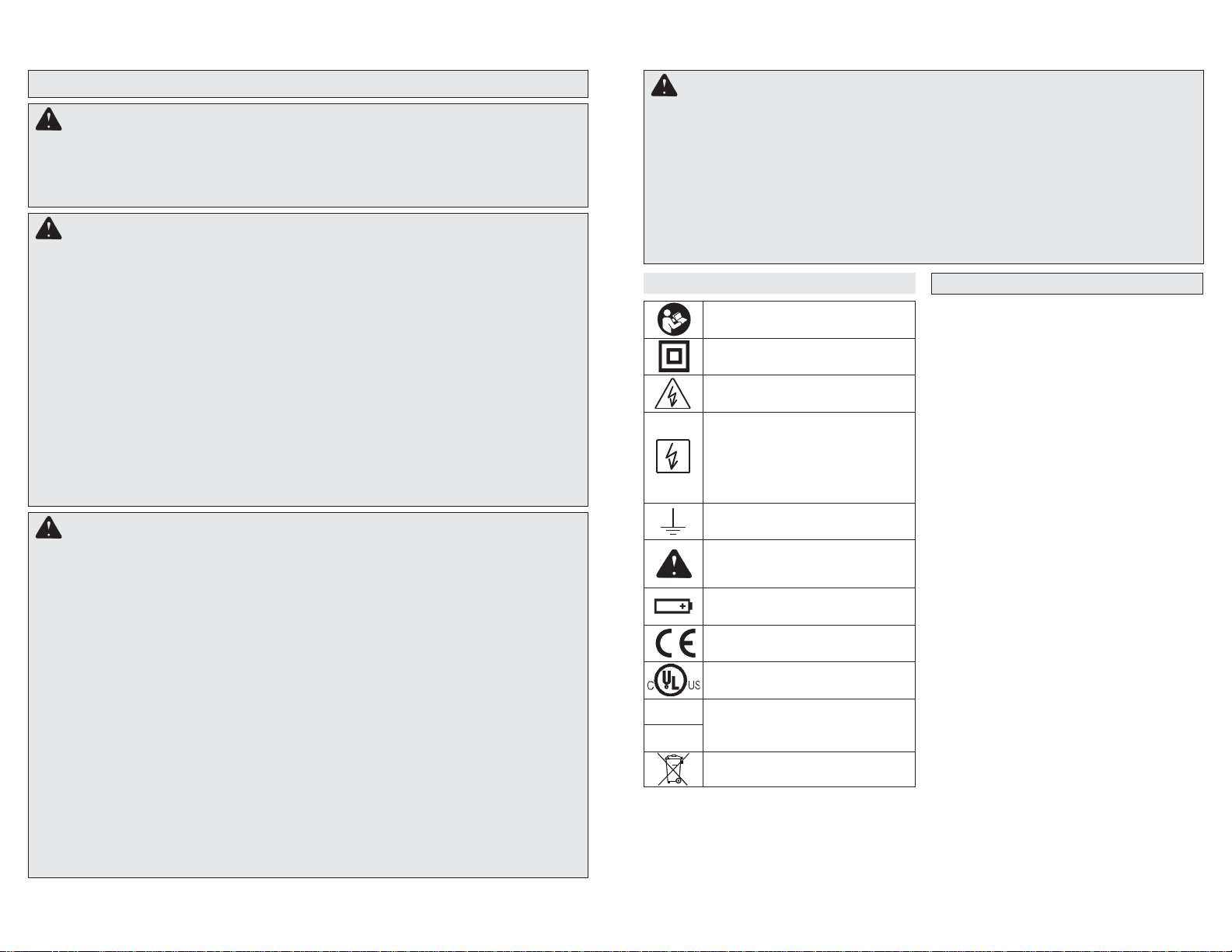
Symbology
Read Operator’s Manual
Double insulation
Risk of electric shock
Indicates that this instrument can
clamp on bare conductors when
measuring a voltage corresponding to the applicable measurement
category, which is marked next to
this symbol.
Earth
Danger, Warning, or Caution Consult the operators manual for
additional safety information.
Battery compartment
European Conformity Mark
Underwriters Laboratories, Inc.,
United States and Canada
Classifi cation of transient overvolt-
ages, based on nominal line voltage
to earth.
Do not dispose of this product as
unsorted municipal waste.
Accuracy is specifi ed for 1 year after calibration, at
operating temperatures of 18°C to 28°C (64°F to
82°F), with relative humidity at 0 % to 85 %.
Maximum voltage between any terminal and
Jaw Opening (maximum conductor size) ....
Temperature ....
Operating: -10°C to 50°C (14°F to 122°F)
Storage: -40°C to 60 °C (-40°F to 140°F)
Temperature Coeffi cient .... 0.1 x (specifi ed
Operating Altitude.... 2,000 meters
IP Rating
(International Dust and Water Protection).... IP54
Drop Test .... 1 Meter
Battery .... 2 AA, NEDA 15 A,IEC LR6
Battery Life .... Approx. 26 Hours all lights on.
Safety Compliances .... EN61010-1, UL 61010-1,
EN61010-031 (Probes),
IEC/EN 61010-1 2nd Edition for measurement
Pollution Degree 2, EMC EN61326-1
Certifi cations .... cULus, CE
3
Lo-Z
Functions
Dial Position Range Resolution Accuracy
Voltage AC/DC
Current AC 200A 0.1A ±(3.0% + 3 dgt) 45-60 Hz
Resistance
Continuity
Capacitance (2206-20)
Current DC (2206-20)
Temperature C° / F°
(2206-20)
Low Input Impedance
Lo-Z
(2205-20)
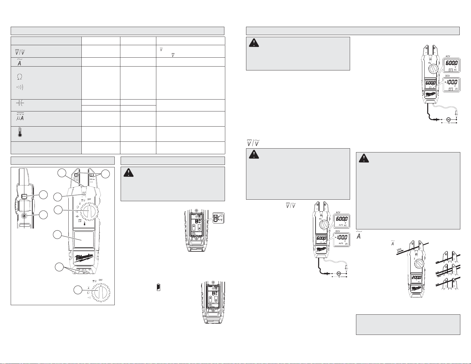
FUNCTIONAL DESCRIPTION
4
2
5
6
1
7
1. Light On/Off button
2. Hold button
3. Jaws
4. Light
5. NCV indicator
6. Dial
7. Display
8. Terminal inputs
8
6
Cat. No.
2205-20
400V
1000V
400.0
4.000k
40.00k
400.0k
4.000M
40.00M
1000F1F
100.0F 0.1F
400.0A
1000A
-40ºC ~ 400ºC
-40ºF ~ 752ºF
400.0V
1000V
3
Cat. No.
2206-20
Lo-Z
To avoid an electrical hazard, turn the Rotary
Dial to OFF and disconnect the test leads
before opening battery compartment or
replacing batteries.
Selecting C° or F°
1. Turn Rotary Dial to OFF and
disconnect the test leads.
2. Unscrew and remove battery door and remove any
installed batteries.
3. Set the C°/F° switch to the
desired position.
4. Replace batteries according
to “Loading/Changing the Batteries.
5. Close the battery door and tighten screw securely.
Loading/Changing the Batteries
Replace batteries when the Low
Battery indicator is displayed.
1. Turn Rotary Dial to OFF and disconnect the test leads.
2. Unscrew and remove battery door.
3. Insert two (2) AA batteries, according
to the polarity marked in the battery
compartment
4. Close the battery door and tighten screw
securely.
4
0.1V/1V
0.1
0.001k
0.01k
0.1k
0.001M
0.01M
0.1A ±(1.0% + 2 dgt)
0.1°C
0.2°F
0.1V/1V ±(2.0% + 3 dgt) AC:45~500Hz
WARNING
: ±(1.5% + 5 dgt) 45-500 Hz
: ±(1.0% + 2 dgt)
±(1.0% + 5 dgt)
±(1.0% + 2 dgt)
±(1.0% + 2 dgt)
±(1.0% + 2 dgt)
±(1.0% + 2 dgt)
±(2.0% + 5 dgt)
±(1.9% + 2 dgt)
C°:±(1% + 2C°)
F°:±(1% + 3 F°)
ASSEMBLY
OPERATION
WARNING
Only use MILWAUKEE test leads with the
MILWAUKEE Fork Meters.
Inspect test leads before each use. Use meter to run a continuity test.
Before Use
Confi rm the Rotary Dial is set to the correct position,
the instrument is set to the correct measurement
mode, and the Data hold function is disabled. Otherwise, desired measurement cannot be made.
LCD Backlight
The LCD backlight will turn off after about 3 minutes
of inactivity. Push any button or turn the rotary dial
to turn the backlight on.
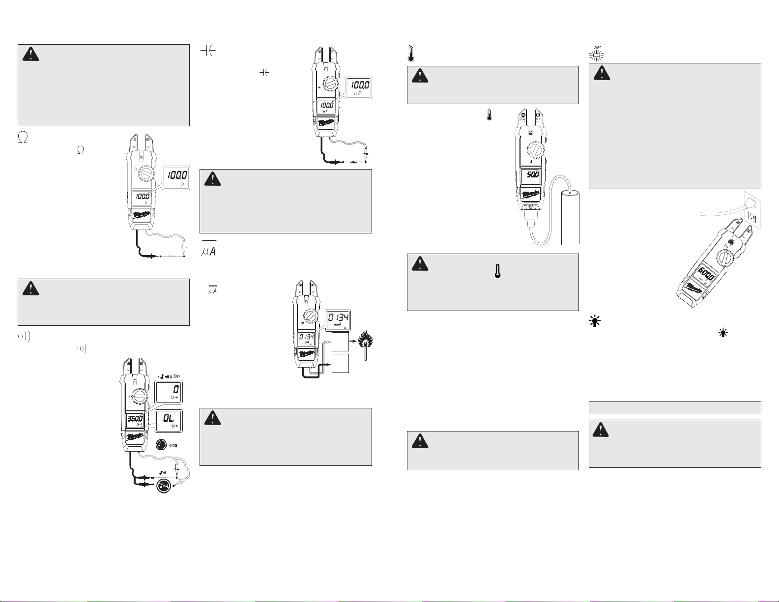
Making a Measurement
Voltage
DANGER
To avoid electrical shock:
Never make measurement on a circuit in
which voltage over AC 1000V or DC 1000V
exists.
Do not use with the Battery Cover removed.
Keep fi ngers behind the guards and away
from test lead tips during measurements.
1. Set the Dial to
tion.
2. Connect the red test lead
to the V terminal and the
black test lead to the COM
terminal.
3. AC: Connect the test leads
to the circuit under test. The
reading is displayed.
DC: Connect the red test
lead to the positive (+)
side and black test leads
to the negative (-) side of
the circuit under test. The
reading is displayed. A reversed connection is
indicated as a negative value.
posi-
Lo-Z Low Input Impedance
(Cat. No. 2205-20 only)
Automatic voltage detection
(AC or DC).
1. Set the Dial to Lo-Z posi-
tion.
2. Connect the red test lead
to the V terminal and the
black test lead to the COM
terminal.
3. AC: Connect the test leads
to the circuit under test. The
reading is displayed.
DC: Connect the red test
lead to the positive (+) side
and black test leads to the negative (-) side of
the circuit under test. The reading is displayed.
A reversed connection is indicated as a negative
value.
DANGER
To avoid electrical shock:
Never make measurement on a circuit in
which voltage over AC 1000V or DC 1000V
exists. Jaws are designed not to short the
circuit under test. If equipment under test has
exposed conductive parts, however, extra
precaution should be taken to minimize the
possibility of shorting.
Do not use with the Battery Cover removed.
Disconnect the test leads from the instrument
for current measurement.
Current
1. Set the Dial to
position.
2. Run the conductor through the
jaws. The reading is displayed.
NOTE: Do not
place 2 or more
wires between
jaws at the same
time. Place wire between arrows. Otherwise,
irregular results will occur.
CAUTION
Maximum conductor size is approx 5/8”
diameter.
5
Correct
Incorrect
Incorrect
DANGER
To reduce the risk of electric shock for
Resistance, Continuity, and Capacitance
measurements, never use the meter on an
energized circuit. Make sure a capacitor is
fully discharged before touching or attempting to make a measurement.
Do not use with the Battery Cover removed.
Resistance
1. Set the Dial to position.
2. Connect the red test lead
to the V terminal and the
black test lead to the COM
terminal.
Confirm “OL” is indicated
on the display, and then
short-circuit the tips of test
leads to make the indication
zero.
3. Connect the test leads to
the both ends of the resistor
under test.
4. The reading is displayed.
CAUTION
After shorting the test leads, the displayed
value may not be zero due to the resistance
of test leads themselves.
Continuity
1. Set the Dial to position.
2. Connect the red test lead
to the V terminal and the
black test lead to the COM
terminal.
Confi rm “OL” is indicated
on the display, and then
short-circuit the tips of
test leads to make the
indication zero. A buzzer
will sound.
3. Connect the test leads
to the both ends of the
conductor under test. If
the resistance under test
is 30 or less, the buzzer
will sound.
Capacitance
(Cat. No. 2206-20 only)
1. Set the Dial to position.
2. Connect the red test lead
to the V terminal and the
black test lead to the COM
terminal.
3. Discharge capacitor.
4. Connect the test leads to the
both ends of the capacitor
under test.
5. The reading is displayed.
DANGER
To avoid electrical shock:
Never make measurement on a circuit in
which voltage over AC 1000V or DC 1000V
exists.
Do not use with the Battery Cover removed.
Current
Flame Rectifi cation Circuit Test
(Cat. No. 2206-20 only)
1. Set the Rotary Dial to
position. DC mark
is displayed.
2. Connect the red test
lead to the V terminal
and the black test lead
to the COM terminal.
Contact the red test
lead to the fl ame sen-
sor probe and the black
test lead to the control
module.
3. Turn on the heating unit. The reading is displayed.
Flame
sensor
probe
Control
Module
CAUTION
When current fl ows from the display side to
the underside of the meter, the polarity is
positive; fl ow from underside to display side,
the polarity is negative.
6
Temperature (Cat. No. 2206-20 only)
WARNING
Never connect the Temperature Probe to an
energized circuit.
1. Set the Rotary Dial to
tion.
2. Connect the K-type Temperature Probe to the input
terminal. The positive (+)
side of Probe should be
connected to V.
3. Place the probe sensor in
the desired location.
4. The reading is displayed.
posi-
Non-Contact Voltage Detection (NCVD)
DANGER
The LED may not be displayed due to installation condition of electrical circuit or equipment. Never touch the circuit under test to
avoid possible danger even if the LED for
NCVD is not displayed.
Check the functionality of LED on a wellknown power supply prior to measurement.
When the LED doesn’t light up, do not make
measurement.
NCVD indication is affected by external voltage, and how the meter is held or placed.
When the meter is on in any
function, the non-contact voltage detector will indicate with a
Red LED on the display when
an electric fi eld exceeding 90V
is detected. Place the edge of
either the jaw near the electric
fi eld.
CAUTION
When the dial is set to , the room temperature should be displayed. If anything else is
displayed, something may wrong with the
meter. Stop using the meter immediately.
HOLD Key
Data Hold Function - Freezes the value on the
display. Press the “HOLD” button to freeze the
reading. The reading will be held regardless of
subsequent variation in input. HOLD is displayed
with the reading. To exit Data Hold mode, press the
HOLD button again.
SMART HOLD: The meter will beep continuously
and the display will fl ash if the measured signal is 50
counts larger than the display reading. (However,
it can not detect across the AC and DC Voltage/
Current)
Worklight LED ON/OFF
To turn the light on and off, press the button.
Over-fl ow indication
Any time the input exceeds the measuring range
“OL” or “-OL” is displayed.
ACCESSORIES
WARNING Always remove batteries
CAUTION
The Data Hold readings are released when the
meter enteres Sleep Mode.
Sleep Mode
The meter is automatically powered off in about 20
min after the last Rotary Dial or button operation.
To reset, turn the Rotary Dial to OFF. If the display
is still blank when a new Rotary Dial setting is
selected, replace the batteries.
The meter does use battery power in sleep mode.
Be sure to switch the tool to OFF to conserve battery power.
before changing or removing accessories. Only
use accessories specifi cally recommended for
this tool. Others may be hazardous.
For a complete listing of accessories refer to your
MILWAUKEE Electric Tool catalog or go online to
www.milwaukeetool.com. To obtain a catalog, contact your local distributor or a service center listed
on the back cover of this operator’s manual.
7
 Loading...