

Milwaukee 2205-20 Service Instructions

MILWAUKEE ELECTRIC TOOL CORPORATION – TEST & MEASUREMENT PRODUCT
REPAIR SERVICE INSTRUCTIONS — CALIBRATION
2205-20 Fork Meter
Environmental
Condition
Perform all calibration at an ambient temperature of 23°C ± 2°C / 73.4°F ± 3.6°F and relative
humidity of 80% - allow the fork meter to sit at this temperature for a minimum of 30
minutes before proceeding.
REPAIR SERVICE
INSTRUCTIONS
Calibration
MILWAUKEE ELECTRIC TOOL CORPORATION
13135 WEST LISBON ROAD ● BROOKFIELD, WISCONSIN 53005-2550 ● USA
58-92-2205d1 04/2010

i
STNETNOC FO ELBAT Page
Introduction 1
1 noitamrofnI ytefaS dna snoituacerP
Symbols 1
Safety 2
Specifications 3
3 noitacificepS lareneG
4 noitacificepS egatloV
5 noitacificepS )noitceteD CA & CD otuA( egatloV Z-oL
5 noitacificepS ecnatsiseR & tnerruC
6 noitacificepS ytiunitnoC
8 scitsiretcarahc tnemnorivne dna lacisyhP
8 ecnailpmoc dna noitacifitreC
9 tnempiuqE deriuqeR
Basic Maintenance 10
01 esaC reteM eht gninepO
01 yrettaB eht gnicalpeR
Performance
Tests 11
11 yalpsiD eht gnitseT
21 noitcnuF egatloV eht gnitseT
21 noitcnuF ecnatsiseR eht gnitseT
31 noitcnuF tnerruC eht gnitseT
Calibration 14
Cleaning 10
Calibation - Continued 15
1
Introduction
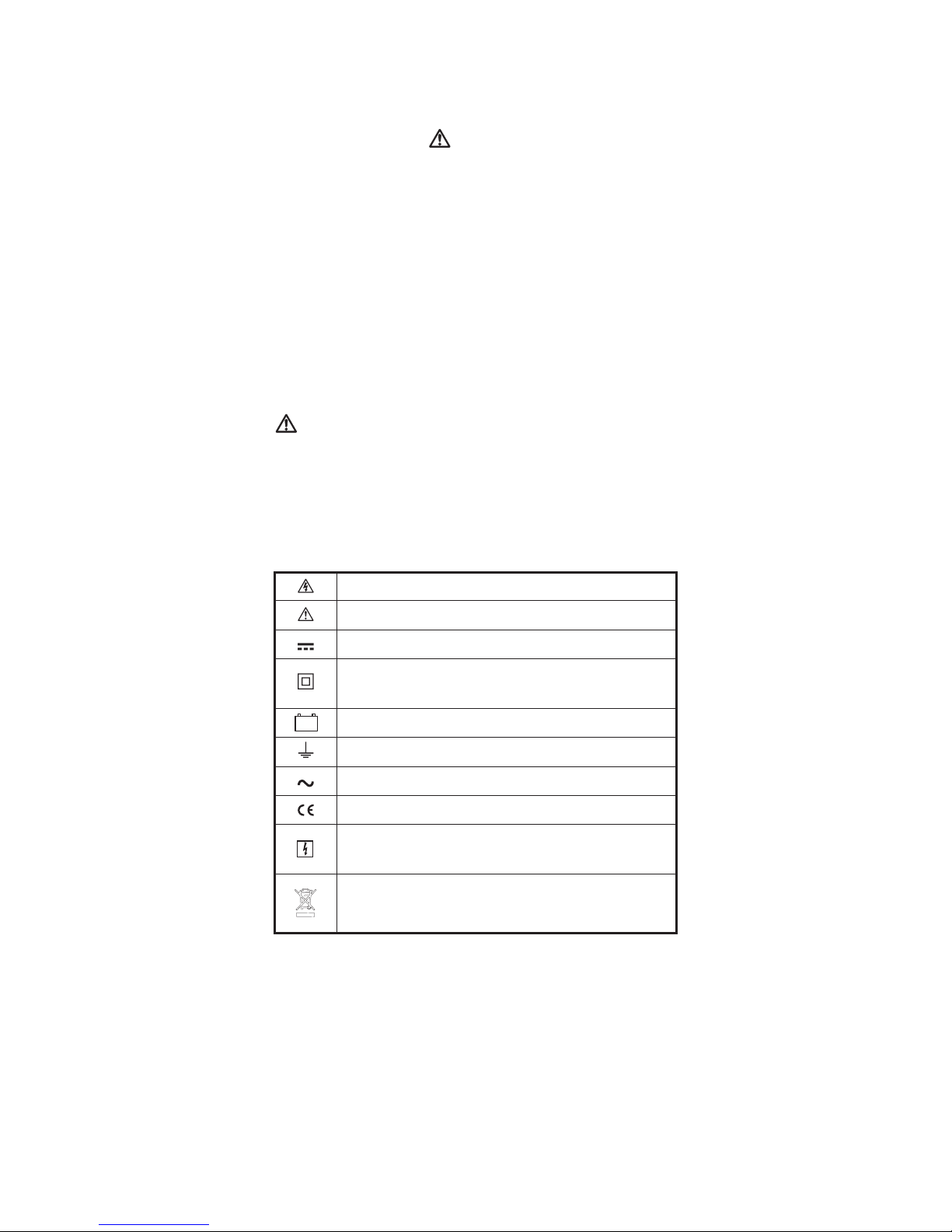
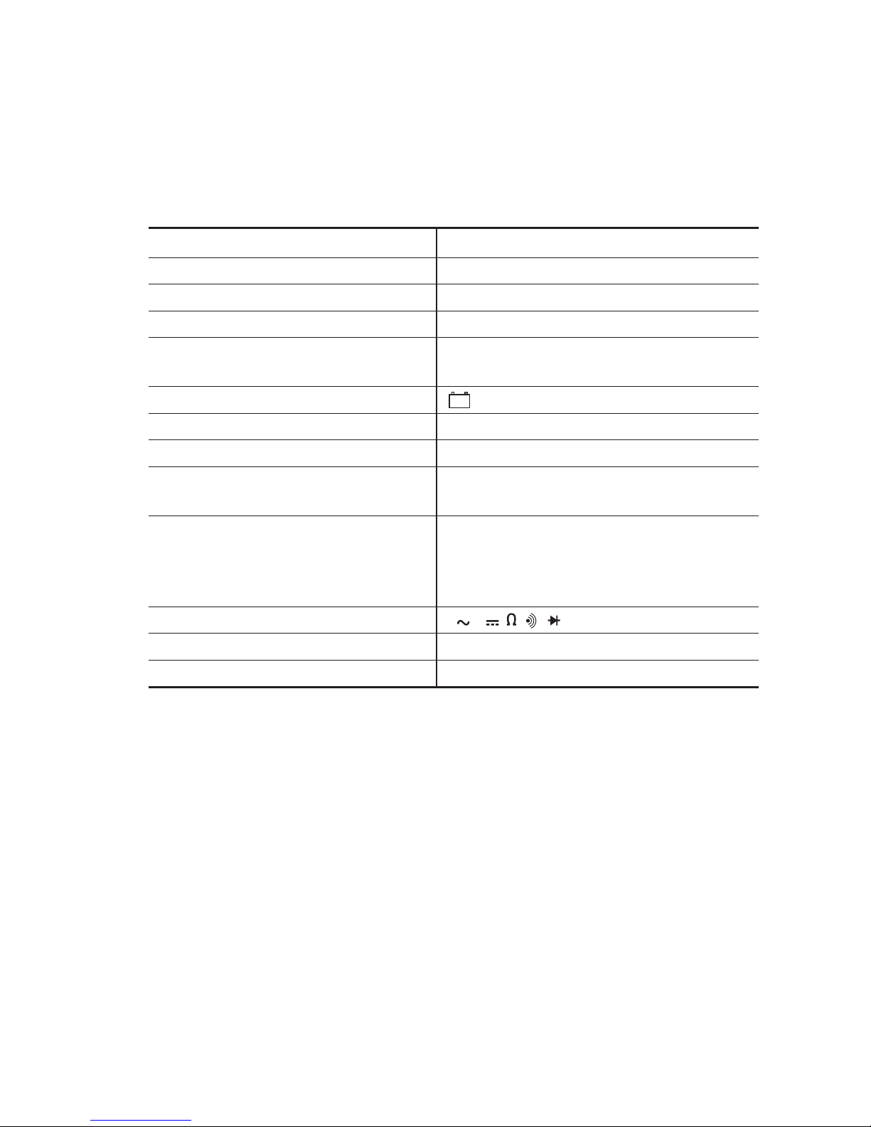
Table A. The Symbols
Risk of electric shock
See instruction card
DC measurement
Equipment protected by double or
reinforced insulation
Battery
Earth
AC measurement
Conforms to EU directives
Application around and removal from hazardous
live conductors is permitted.
Do not discard this product or throw away.
++
WARNING
To avoid shock or injury, do not perform the verification tests or calibration procedures
described in the manual unless you are qualified to do so.
The information provided in this document is for the use of qualified personnel only.
CAUTION
The 2205-20 contain parts that can be damaged by static discharge.
Follow the standard practices for handling static sensitive devices.
Precautions and Safety Information
Use the Meter only as described in the Operator’s Manual. If you do not do so, the protection provided
by the Meter may be impaired. Read the “Safety Information” page before servicing this product.
In this manual, a WARNING identifies conditions and actions that pose hazard (s) to the user; a
CAUTION identifies conditions and actions that may damage the Meter or the test instr
uments.
The Symbols
The symbols used on the Meter and in this manual are explained in Table 1.

2
SAFETY
Review the following safety precautions to avoid injury and prevent damage to this product or
products connected to it. To avoid potential hazards, use the product only as specified.
CAUTION: These statements identify conditions or practices that could result in damage to
the equipment or other property.
WARNING: These statements identify conditions or practices that could result in personal
injury or loss of life.
Specific precautions
Do not operate without covers. To avoid personal injury, do not apply any voltage or current to
the product without covers in place.
Electric overload. Never apply a voltage to a connector on the product that is outside the range
specified for that connector.
Avoid electric shock. To avoid injury o
r loss of life, do not connect or disconnect probes or test
leads from the meter while they are connected to a voltage source.
Do not operate in wet/damp conditions. To avoid electric shock, do not operate this product in
wet or damp conditions.
To reduce the risk of injury, user must read and understand operator’s manual.
3
SPECIFICATIONS
All specifications are warranted unless noted typical and apply to the 2205-20.
Stated accuracies are at 23°C±5°C at than 80% relative humidity and without the battery
indicator displayed.
General specifications
noitpircseD scitsiretcarahC
stnuoc 0004 tnuoc yalpsiD
ces / semit 3 etar etadpu ciremuN
citamotuA yalpsid ytiraloP
Overrange display
Display "OL" when the reading exceeds
range by 10%
Low voltage indicator is indicated
setunim 02 emit ffo-rewop citamotuA
ezis AA ro 6RL CEI 2 * V5.1 ecruos rewoP
Maximum input voltage
600V CAT IV between V and COM
1000V CAT III between V and COM
Maximum floating voltage
600V CAT IV between any terminal and earth
ground
1000V CAT III between any terminal and earth
ground
V connector V , V , , ,
C°82> ro C°81< ,C° / )ycaruccA .cepS(×1.0 tneiciffeoC erutarepmeT
)enilaklA( lacipyt sruoh 65 efiL yrettaB
++
4
Measurement Characteristics
Accuracy is ±(% reading + number of digits) at 23°C ± 5°C <80% R.H.
Temperature coefficient: 0.2×(specified accuracy)/°C, <18°C >28°C
(1) DC Voltage
Range Resolution Accuracy
400.0V 0.1V
1000V 1V
±(1% reading + 2 digits)
Input Impedance: 1MΩ
Response Time: < 1.5 sec.
Overload Protection: AC/DC 1200V for 10 second.
(2) AC Voltage
Range Resolution Accuracy (Sine Wave)
400.0V 0.1V
1000V 1V
±(1.5% reading + 5 digits)
Input Impedance: 1MΩ // less than 100pF
Frequency Response: 45 ~ 500Hz (Sine Wave)
AC Conversion Type: AC coupled average sensing, RMS indication
Additional Accuracy by Crest Factor (C.F.): Add 6.0% for C.F. 1.0 ~ 2.0.
Add 7.0% for C.F. 2.0 ~ 2.5.
Add 9.0% for C.F. 2.5 ~ 3.0.
Max. Crest Factor: 2.0 for 4000 ~ 3000 digits
3.0 for 3000 ~ 0 digits
Response Time: < 2 sec. when the LCD reading is bigger than 1000 digits in each range.
Overload Protection: AC/DC 1200V for 10 second.
 Loading...