

Page 1
military visualizations
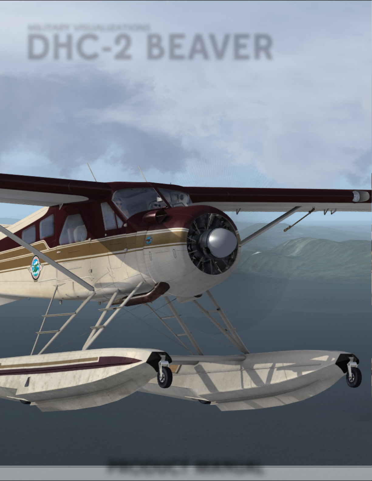
DHC-2 BEAVER
military visualizations
DHC-2 BEAVER
PRODUCT MANUAL
Page 2

This manual is for ight simulation use only.
Do not attempt to use any part for real ight operations.
military visualizations
DHC-2 BEAVER
Page 3

This software is an artistic representation of the subject matter.
Military Visualizations Inc. does not endorse, nor in turn, is endorsed by the
manufacturer(s) of the depicted subject matter.
This software, including any and all components and content, © 2017 Military
Visualizations Inc. All Rights Reserved.
No replication, reduction, reverse engineering or unauthorized addition to the
software, either in whole or in part, is permitted in any form without the express
written permission of Military Visualizations Inc.
by installing this software, you are hereby agreeing to the above terms and
conditions. Any breach of the above EULA will result in litigation, removal of
license and/or forfeiture of continued support.
Any inquiries regarding commercial, military or academic use of this program
should be directed via e-mail to [email protected]
military visualizations
DHC-2 BEAVER
Page 4

TABLE OF CONTENTS
Introduction 1
1. Features & Highlights 2
1.1. Introducing the MilViz DHC-2
1.2. Special Features
2. Installation & Conguration 5
2.1. System Requirements
2.2. Installation Instructions
2.3. Realism Settings
2.4. MVAMS Operation
2.5. In-Game Conguration
2.6. Product Support
3. Description Of Aircraft 14
3.1. General
3.2. Dimensions
3.3. Gross Weight
3.4. Engine
3.5. Engine Controls
3.6. Propeller
3.7. Oil System
3.8. Fuel System
3.9. Fuel System Controls
3.10. Electrical System
3.11. Flight Control System
3.12. Wing Flaps
3.13. Landing Gear System
3.14. Instruments
3.15. Emergency Equipment
3.16. Seating Arrangement
3.17. Heating System
3.18. Ventilation System
military visualizations table of
DHC-2 BEAVER
CONTENTS
Page 5

TABLE OF CONTENTS, CONTINUED
4. Normal Procedures 28
4.1. Before Entering Aircraft
4.2. On Entering Aircraft
4.3. Before Starting Engine
4.4. Starting Engine
4.5. Engine Warm-up
4.6. Engine Ground Tests
4.7. Taxiing
4.8. Take-o Check
4.9. Take-o
4.10. Climb
4.11. Cruise
4.12. Descent
4.13. Approach
4.14. Landing
4.15. Go-around and Baulked Landing
4.16. After the Landing
4.17. Post Flight Checks
4.18. Stopping the Engine
5. Emergency Procedures 36
5.1. Engine Failure
5.2. Dead Engine Landing
5.3. Propeller Failure
5.4. Ditching
6. Operating Limits, 41
Performance Data
and Flight Characteristics
6.1. General Remarks
6.2. Engine Limitations
6.3. Propeller Limitations
6.4. Residual Fuel Quantities
6.5. Airspeed Limits
6.6. Acceleration Limits
6.7. Weight Limitations
6.8. Minimum Flight Crew
6.9. Miscellaneous
military visualizations table of
DHC-2 BEAVER
CONTENTS
Page 6

TABLE OF CONTENTS, CONTINUED
6.10. Performance at Maximum
Gross Weight
6.11. Flight Characteristics
7. Special Installations 48
7.1. Combination Wheel-Ski
Installation
7.2. Amphibious Floats
8. Operating Data Charts 52
8.1. Take-o Distance - Landplane
8.2. Landing Distance - Landplane
8.3. Skiplane Take-o and Landing
Distances
8.4. Take-o Distance - Seaplane
8.5. Landing Distance - Seaplane
8.6. Cruise Power Chart
Credits 59
military visualizations table of
DHC-2 BEAVER
CONTENTS
Page 7
INTRODUCTION
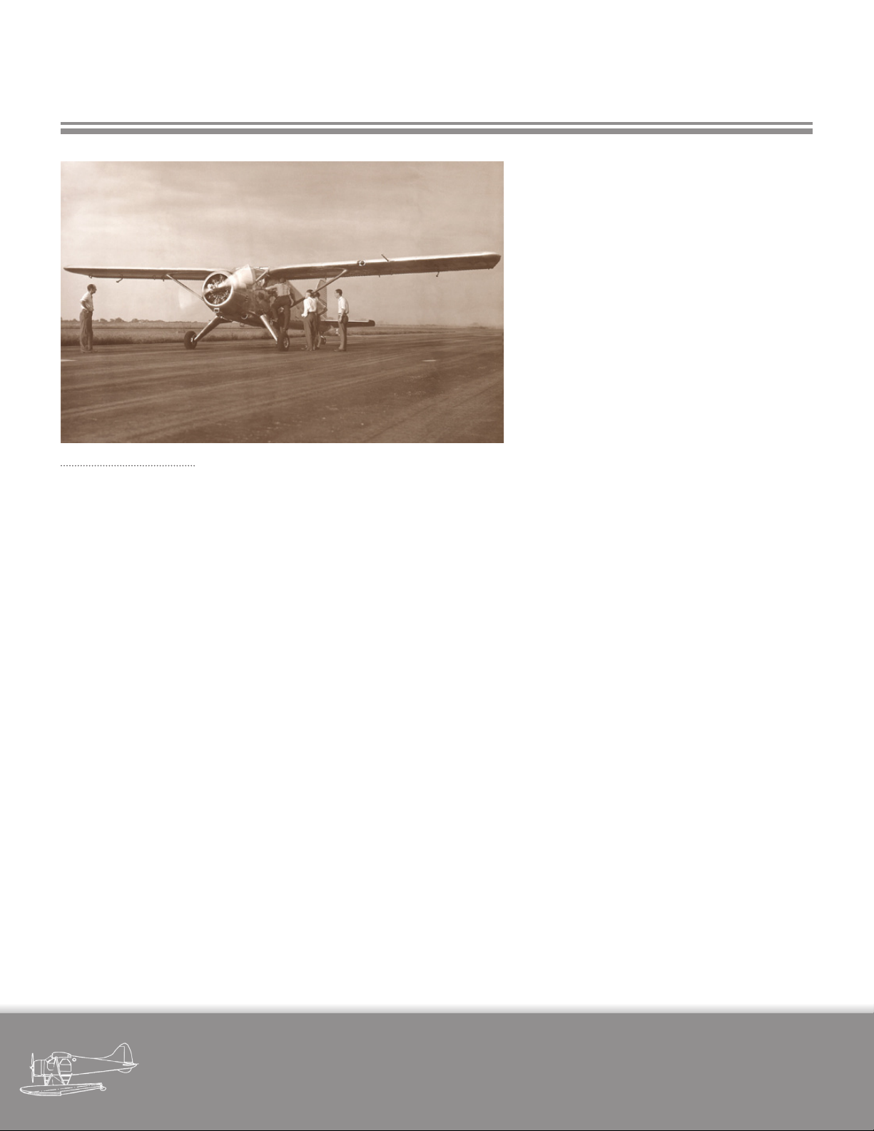
CF-FHB, tH e Fi rst
pr otot ype Be aver,
pi Ctur ed d uri ng e ar-
ly te sts in aug ust
1947
ne of the greatest achievements in Ca-
O
nadian aviation isn’t measured by military prowess, nor by how advanced it may
have been for its time, nor by even how fast
or how high it may have own.
Instead, it’s measured in usefulness and reliability, in year after year and mile after nautical mile of ying in poor weather and far
ung regions where other aircraft just don’t
dare.
It’s measured by the fact that almost 70 years
after it rst took to the air, not only is it still
ying in large numbers, but it’s still desired
and used for the exact same purpose for
which it was conceived.
The story of the deHavilland DHC-2 Beaver
isn’t just a tale of a successful aircraft, it’s a
story of people and determination, of wise
and considered engineering in an era when
getting the job done - and done right - was
what mattered most.
The Beaver is an aircraft to be truly proud of,
to admire and respect; not just from a perspective of national pride but also for all who
have an interest in aviation’s past, for anyone
who wishes to see where we’ve come from
and in turn, witness where we’re going.
Here at MilViz, we’re very proud to have this
opportunity to recreate this legendary aircraft for desktop simulation.
For many, desktop simulators often transcend the idea of ‘game’ or ‘entertainment’.
In addition to the simple enjoyment experienced from even the simulated act of ying,
our computers can also become windows to
a world which many of us may not have the
opportunity to experience rst-hand, or even
to chapters of history long since passed.
To this end, we sincerely hope that we have
succeeded in providing you, the user, with
an enjoyable and accurate simulation of
what we feel is a very remarkable aircraft.
No other aircraft so personies a ‘can-do’
attitude, the very same attitude that has
summed up those countless pilots and small
operators bringing distant frontiers that
much closer to civilization.
military visualizations page
DHC-2 BEAVER
1
Page 8
1. FEATURES & HIGHLIGHTS
1.1 Introducing the MilViz DHC-2
The MilViz DHC-2 has been designed from the start to
replicate and deliver an authentic Beaver experience.
Many aircraft developed for FSX and Prepar3D feature
limitations on ight modelling that prevent the full ight
envelope from being simulated. With our DHC-2, we are
actively incorporating carefully designed ight dynamics in order to realistically represent the unique characteristics of this iconic aircraft.
The DHC-2 Beaver was never designed to be a dicult
aircraft to y - not in real life, and not in the simulator.
However, just as in the real aircraft, the engine, pitch
trim, and aps will all need to be carefully managed in
order to stay within safe ying practices. Stalls can and
will develop if you approach the edge of the ight envelope without heeding proper operational limits.
We have also thoughtfully approached the day to day
operation of the actual aircraft and replicated what we
were able to within the limitations of a simulation platform.
The DHC-2 Beaver was engineered with certain features
that are uncommon in more recent aircraft. We’ve strived
to include some of these unique features in our model.
When you start the MilViz DHC-2, one of the rst things
you will be required to do is to pressure up the fuel system prior to engine start. Wobble pumps aren’t unique
to the Beaver, but we’ve included a fully operable pump
handle that you’ll need to become acquainted with.
As in the real aircraft, aps in the DHC-2 are operated by
means of a hydraulic pump located under the pilots seat.
A pump handle is used to provide pressure and with each
stroke, the aps are raised or lowered a small amount. A
military visualizations page
DHC-2 BEAVER
2
Page 9
SECTION 1 - PRODUCT FEATURES & HIGHLIGHTS
selector is used to determine whether the pilot is raising
or lowering the aps.
Functional circuit breakers are present for important
electrical systems, such as the adjustable lighting and
myriad of various avionics options available.
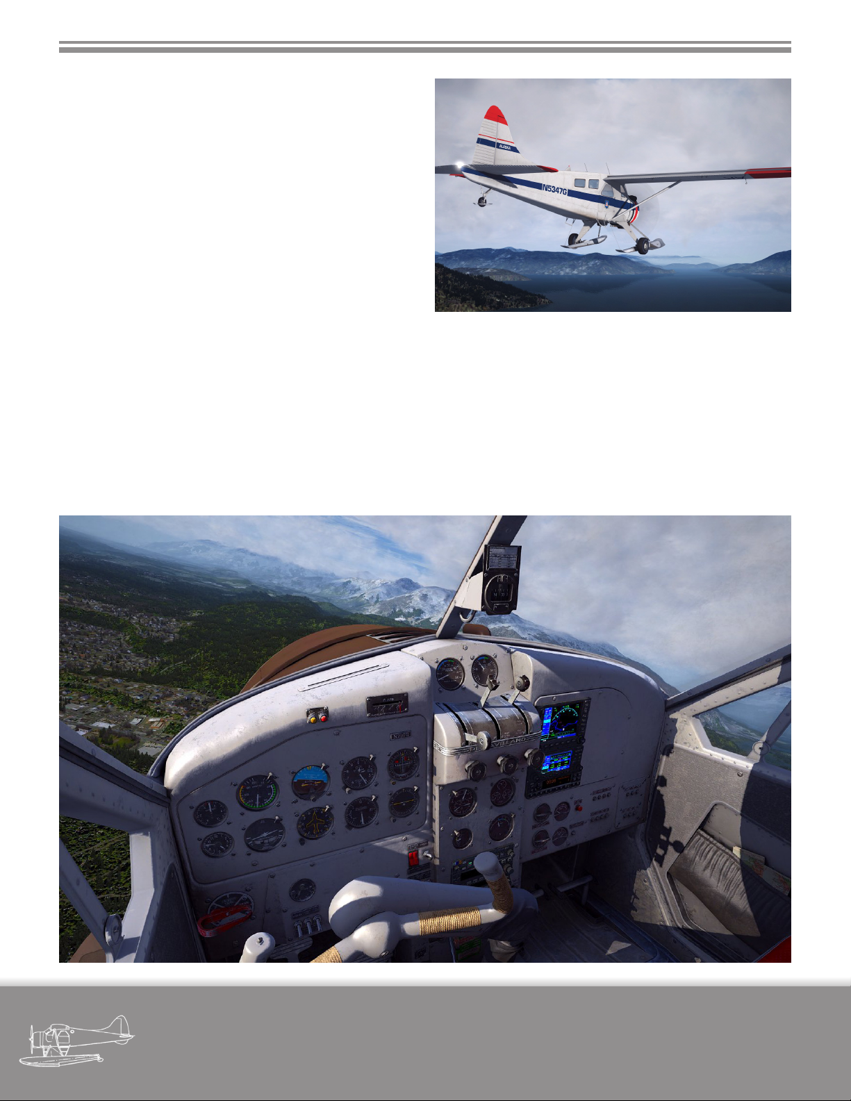
Does that yoke column prevent you from accessing or
seeing your switches, or would you simply like to see
what the view might be like from right hand seat? The
throwover ability of the yoke installed in the MilViz DHC2 is actually functional and animated - able to be positioned with the mouse anywhere along it’s travel.
conguration, inside or out. We’ve strived to hold true to
Our simulation doesn’t stop there, of course. There are
hundreds of smaller details that have been faithfully researched and recreated.
In truth, one of the more interesting aspects of recreating
an aircraft such as this is that because it’s been in service
as a workhorse for so long, that there’s really no standard
this aspect as well, with multiple models and a large se-
lection of conguration options available.
With so many stories that the MilViz DHC-2 is capable of
telling, where will your Beaver take you?
military visualizations page
DHC-2 BEAVER
3
Page 10

SECTION 1 - PRODUCT FEATURES & HIGHLIGHTS
1.2 MilViz DHC-2 Special Features
Professionally created & tuned, high delity ight model including accurate characteristics specic to
the DHC-2.
Four Body Congurations - Standard Wheels, Amphibious Floats, Skis, Tundra Tires, each with specically
tuned ight models.
Two Body Styles - Passenger version with enlarged rear windows, cargo version with original round rear
windows and cargo with selectable visibility.
Custom fuel system with primer pump and wobble pump emulation; engine start takes into account
current engine temperature and includes potential for over-priming & ooding.
Custom electrical system with display of electrical load and operable circuit breakers.
Unique ap operation which simulates the usage of the manually operated hydraulic pump and selector
on the DHC-2.
Icing eects on airframe and static instruments fully simulated.
Functional and animated throwover ability on control column; ability to completely hide yoke and col-
umn for ease of access to important switches and controls.
Hydraulic hand pump based on the original DHC design used in the Amphibious and Ski versions.
Highly accurate and beautifully recreated exterior and interior 3D models.
Richly detailed cabin with beautiful high resolution textures and smoothly operating gauges.
Realistic and fully adjustable cabin and instrument lighting.
Authentic sound environment, helping to enhance immersion and replicate the feel of a powerful 9 cyl-
inder radial thumping away mere feet from the rewall.
Milviz / REX WX Advantage Weather Radar included and available as a 3D panel option.
Highly congurable avionics with 3D panel installations for many GPS solutions, covering popular 3rd
party add-ons such as Flight1 GTN, RealityXP GNS, and Mindstar GNS.
Professionally created liveries based on or inspired by real world aircraft.
Available layer-based paintkit for creating your own liveries.
military visualizations page
DHC-2 BEAVER
4
Page 11

2. PRODUCT INSTALLATION
& CONFIGURATION
2.1 System Requirements
The following requirements apply as a minimum to successfully install and operate the MilViz DHC-2.
Please note that choice of scenery, location, simulator
settings and 3rd party utilities may place additional
demands on your simulation platform.
2.1.1 Supported Platforms:
Microsoft Flight Simulator X, Service Pack 2 (SP2)
Note: Service Pack 2 is required, aircraft may not function correctly with Service Pack 1 or earlier. The Acceleration expansion pack is fully supported but not
required.
Microsoft Flight Simulator X, Steam Edition
Lockheed Martin Prepar3D, version 2
2.1.3 Processor (CPU)
2.4 GHz single core processor required (3.0 GHz, mul-
tiple core processor or better recommended)
2.1.4 Video Card (GPU)
DirectX 9 compliant video card with 1024 MB video
ram
2.1.5 System Memory (RAM)
4 GB RAM
2.1.6 Hard Drive
2.5 GB or greater hard drive space
2.1.7 Gaming Controller
Joystick, yoke, or other gaming controller
Lockheed Martin Prepar3D, version 3
Note: Our product is tested with and designed for the
most recent update to Prepar3D version 3 (version
3.4 at the time of this publication); this includes all
hotxes available. For compatibility with any future
updates and hotxes to version 3, please register for
and visit our product forums. Compatibility with future versions of Prepar3D is not implied nor included.
2.1.2 Supported Operating Systems:
Windows Vista
Windows 7
Windows 10
military visualizations page
Note: All MilViz products require a functioning gaming device such as a joystick for proper operation.
DHC-2 BEAVER
5
Page 12
SECTION 2 - PRODUCT INSTALLATION & CONFIGURATION
2.2 Installation Instructions
Important: As with other ight simulator addons, pre-installation precautions should involve closing other open
applications, as well as temporarily disabling any active antivirus software. Please be sure to remember to re-enable
your antivirus software after installation!
After purchase, you will have been given a link or an option to download a zipped (.zip) le. This compressed le
contains an executable (.exe) le, which is the installer for the MilViz DHC-2.
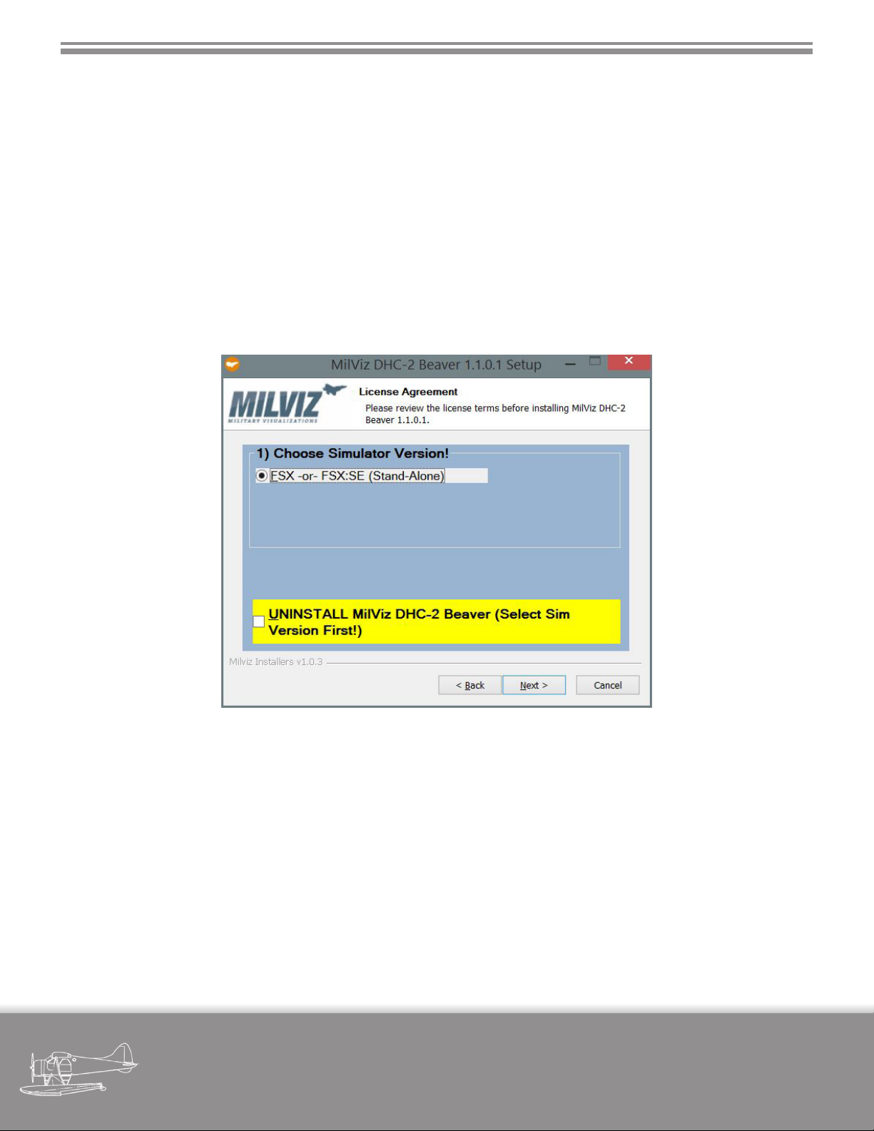
To begin installation, please right click on the executable le and select “Run as administrator”. After clicking through
on the initial setup screen and reviewing and agreeing to the license terms, you will come to the main installation
window (below).
2.2.1 Choosing your Simulator
For a new installation, you are able to select a single option from a list of possible simulators to install into. The installer will automatically detect which simulators you have installed, and present you with only those selections.
Please note that you may only install into one simulator at a time; if you have more than one simulator installed on
your computer, you are able to install to multiple simulators by re-running the installer and choosing a dierent
simulator version.
Click on the “Next” button to continue with the installation process.
military visualizations page
DHC-2 BEAVER
6
Page 13
SECTION 2 - PRODUCT INSTALLATION & CONFIGURATION
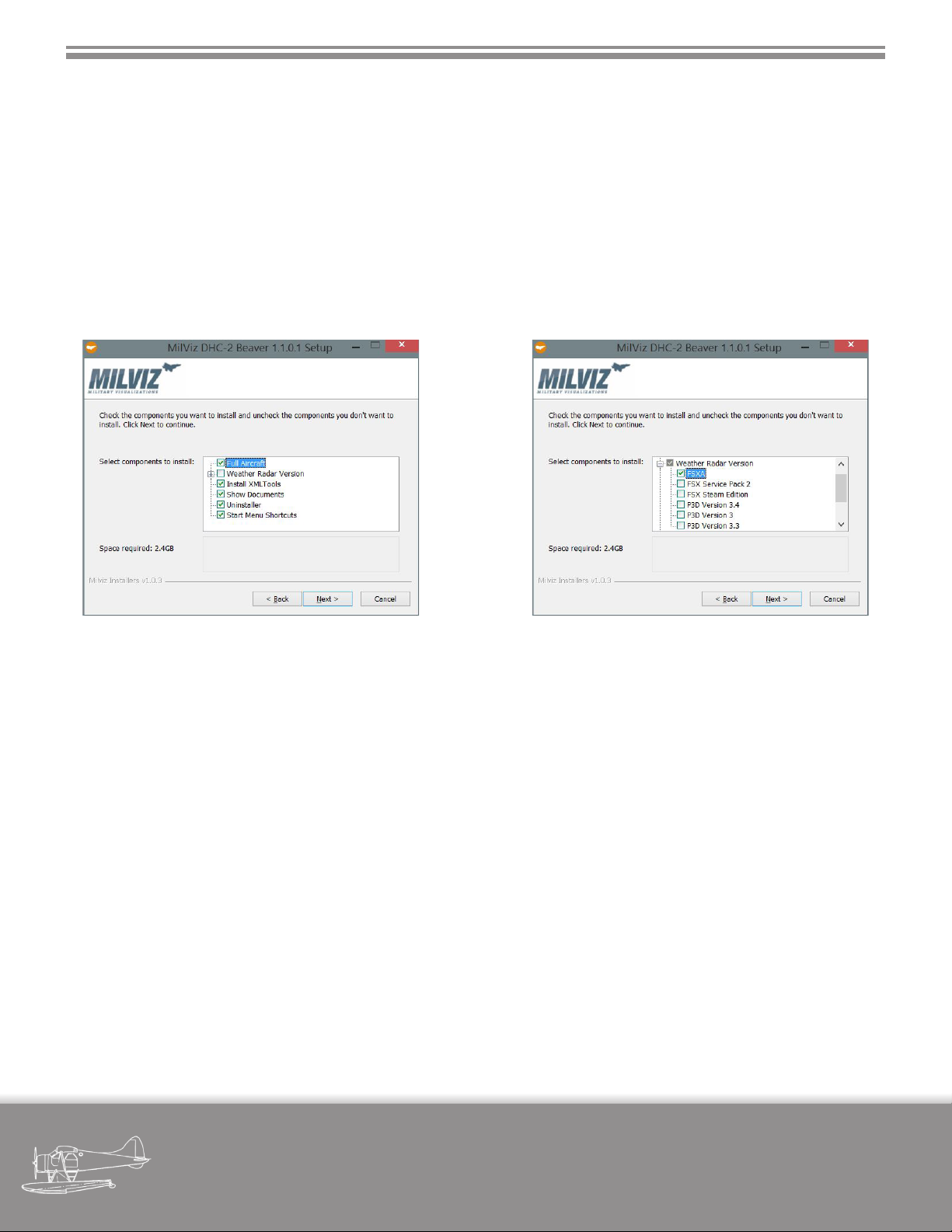
2.2.2 Component Selection
The next screen will allow you to select (or deselect) various components that make up this installation. Although it’s
possible to do so, we don’t really recommend deselecting any of the default options. In particular, XMLTools (a small
utility that extends programming capabilities) is installed by default alongside the DHC-2, and is required for correct
functionality of the aircraft.
The one area where you may freely make your own selections is within the ‘Weather Radar Version’ area. The MilViz
DHC-2 Beaver ships complete with a copy of the MilViz / REX WX Advantage Weather Radar; you may use the selections here to install this add-on into any applicable simulator(s). When ready, click on the ‘Next’ button to continue.
2.2.3 Conrming Install Location
The last window that comes up should be pre-completed with the location of your selected simulator. If this isn’t the
case, or you wish for some other reason to change the simulator location that is detected, you may do so here.
When you are ready, click on the ‘Install’ button to proceed with the installation. During the installation process, you
will see the progress of les being copied. Near the end, the installer for XMLTools will also display; please follow the
prompts on this installer to ensure that XMLTools is properly installed.
2.2.4 Uninstalling
To uninstall the MilViz DHC-2 Beaver, simply run the installer, select your simulator version that you wish to uninstall
from, then click on the checkbox option that reads “UNINSTALL...”, and nally click on the “Install” button to start the
uninstallation process.
Please note: This operation will only uninstall the MilViz DHC-2 Beaver from the selected simulator. To remove the
product from multiple simulators, please re-run the installer and choose dierent simulator versions. Please be sure
to back up any personalized les you may wish to keep prior to uninstallation.
military visualizations page
DHC-2 BEAVER
7
Page 14
SECTION 2 - INSTALLATION & CONFIGURATION
2.3 Realism Settings
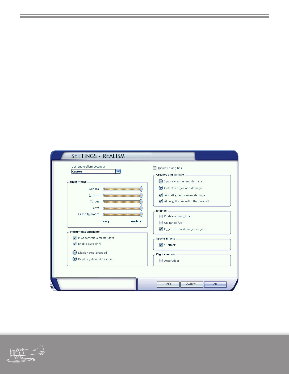
The MilViz DHC-2 Beaver has been carefully built with a very high level of accuracy in mind. Development and testing
have both been carried out using the highest realism settings available within the simulator.
In both FSX and P3D, the settings available within the Realism panel consist of changes designed to not only make
the aircraft easier to y, but to also lessen the workload of the pilot. The goal is to ensure that any settings that might
impact your full enjoyment of the MilViz DHC-2 Beaver are correctly set.
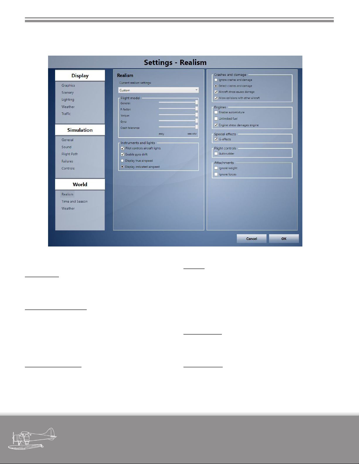
The following images of the settings for FSX and P3D are meant to oer the most realistic depiction of the both the
ight model as well as the general operation of the aircraft. Without these settings in place, particularly in regards to
the ight model section, the aircraft may not perform as intended.
2.3.1 Realism Settings - FSX
military visualizations page
DHC-2 BEAVER
8
Page 15
SECTION 2 - INSTALLATION & CONFIGURATION
2.3.2 Realism Settings - P3D
2.3.3 Description of Settings
Flight Model
For the highest degree of realism, all sliders in the ight
model section should be set fully to the right.
Instruments and Lights
The MilViz DHC-2 has a sophisticated lighting system
in place, so the “Pilot controls aircraft lights” should be
checked. “Enable gyro drift” and “Display indicated airspeed” are not essential, but they do add to the realistic
operation of any aircraft.
Crashes and Damage
These settings aren’t essential, but do add to the sense of
safe operation of the simulation.
military visualizations page
Engines
“Enable automixture” should be disabled to allow for
functionality of the mixture lever. “Unlimited fuel” is non-
essential, but disabling does allow for simulating fuel
management. “Engine stress damages engine” is not es-
sential, but being present does introduce risk for engine
mismanagement (Acceleration only).
Special eects
“G-eects” can be enabled to allow for screen eects to
occur in excessive high or low G situations.
Flight Controls
“Autorudder” should be o so long as you have means to
operate the aircraft rudder via rudder pedals or a twist
axis on your joystick.
DHC-2 BEAVER
9
Page 16
SECTION 2 - INSTALLATION & CONFIGURATION
2.4 MVAMS Operation
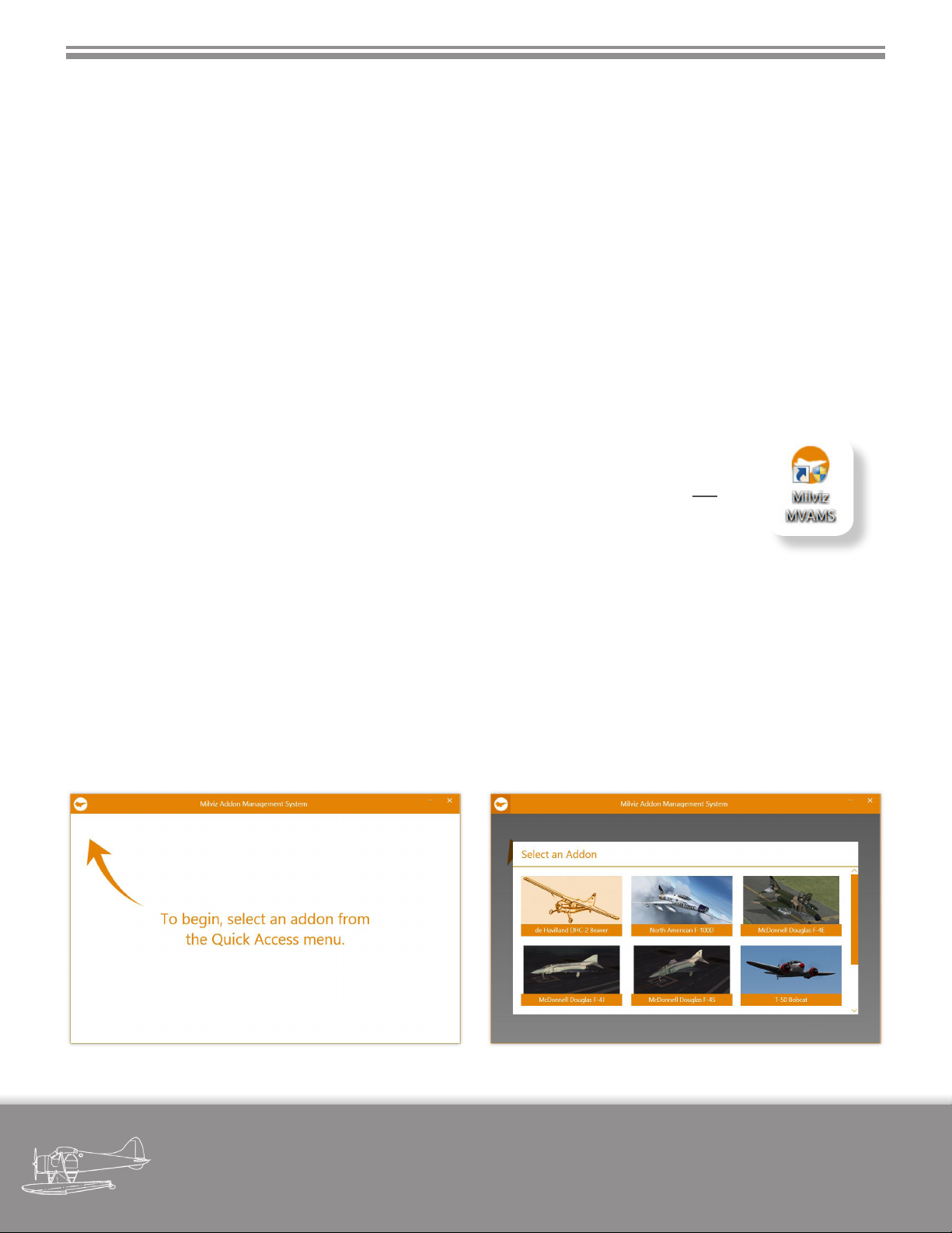
MVAMS stands for MilViz Addon Management System. It represents our easy-to-use solution to the growing complexity of congurable options and choices available in our aircraft.
MVAMS is a standalone application which is installed and utilized by many of our newer releases. It was our aim to
create a user-friendly environment in which our aircraft could be easily and quickly congured in terms of visual options, avionics, loadout, etc.
The MilViz DHC-2 Beaver installs (if not already present) and fully integrates with the MVAMS application, allowing
the user to choose between the diering body styles, passenger or cargo load and visibility, and avionics options.
2.4.1 Starting MVAMS
If this is your rst MilViz product that includes the MVAMS application, running the installer
will place a shortcut icon on your desktop. If this is not your rst MVAMS equipped MilViz
aircraft, the desktop shortcut icon may already exist.
You may use this icon to open the MVAMS application at any time while the simulator is not
running to congure your DHC-2 Beaver to your preferences.
After your installation is complete, the MVAMS application will open automatically. You are
not required to congure your aircraft at this time; you may choose to close it if you wish.
2.4.2 Selecting your Aircraft
When you open the MVAMS application, you are presented with the instruction to select an addon from the Quick
Access menu. Clicking on the top left icon will bring up visual icons of any installed MilViz addons which are integrated with the MVAMS application.
Your newly installed DHC-2 Beaver will now be available to select.
military visualizations page
DHC-2 BEAVER
10
Page 17
SECTION 2 - INSTALLATION & CONFIGURATION
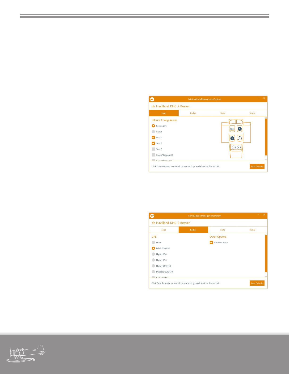
2.4.3 Conguring the DHC-2
One feature that we’ve designed into our MVAMS application is that only options that are particular to the aircraft
in question are available to browse and select, meaning that you won’t see military specic loadout options in your
general aviation aircraft, nor will you see GPS options in your Century Series ghter jet.
For the DHC-2, four conguration tabs are available, with the rst pertaining to the fuselage style and interior load,
the second pertaining to the various radio & avionics options, the third being where you set the initial start-up state
of the DHC-2, with the last tab pertaining to miscellaneous visual options.
2.4.4 Load
In the rst tab, you can switch the interior layout between a passenger conguration and a cargo layout by
clicking on the appropriate radio button. This change
also has a visual eect on the fuselage, with the cargo
layout retaining the original rearmost round windows.
Selecting between either option presents a dierent list
of checkboxes which, by selecting any or all, changes the
visual presence of passengers or cargo when the aircraft
is loaded.
The selection of passengers or cargo from this screen
also aects the weight of the aircraft in the simulator.
2.4.5 Radios
The second tab allows you to switch between various
avionics options. A range of third party GPS solutions is
allowed for, as well as support for the included Milviz /
REX WX Advantage Weather Radar.
The ‘None’ option allows you to congure your cabin
with analog radios only, while the Milviz 530/430 option
displays the provided Milviz GPS units that are included
with the aircraft.
All other GPS options require a functioning installation
of a third party add-on which is not included with the
Beaver.
military visualizations page
DHC-2 BEAVER
11
Page 18
SECTION 2 - INSTALLATION & CONFIGURATION
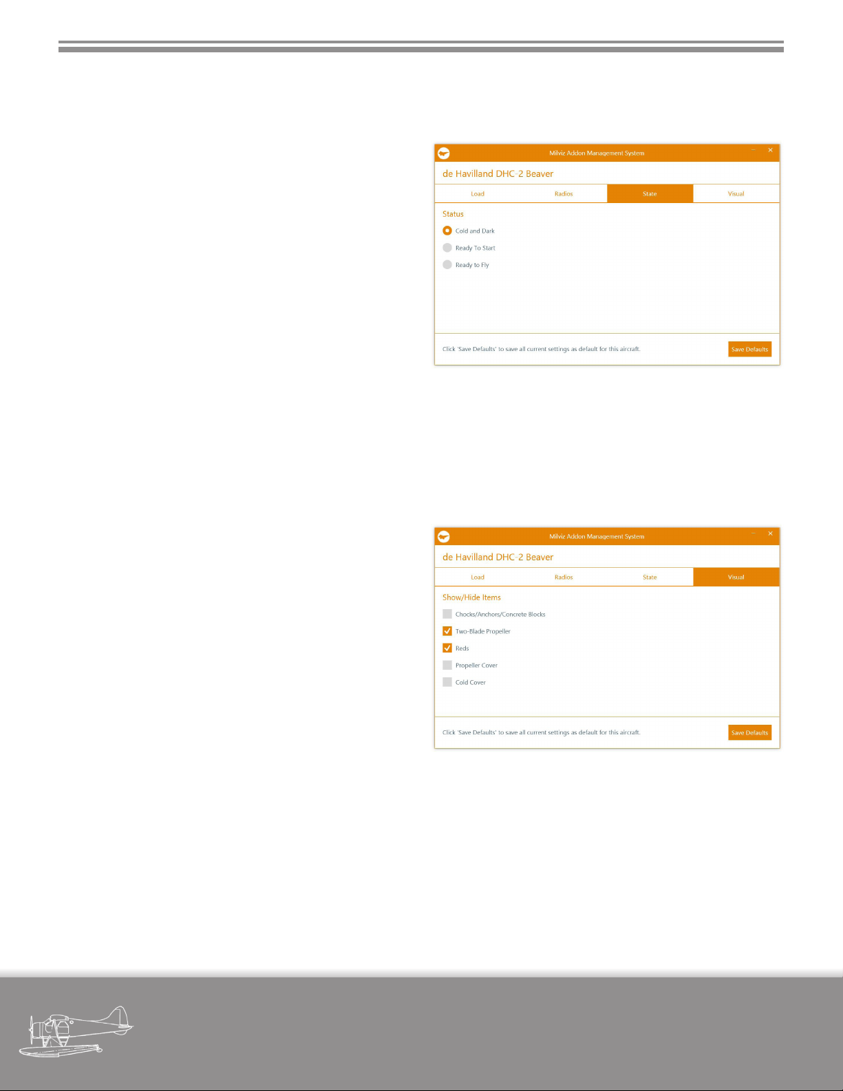
2.4.6 State
The State tab allows you to specify the start-up state of
the Beaver upon loading the aircraft in the simulator.
Cold and Dark allows for a completely cold and powered down aircraft, where you will have to run through a
proper start-up routine to begin your ight. The aircraft
is loaded as such regardless of saved ight status.
Ready to Start loads the aircraft with systems such as battery and lights being on, with the engine ready to start.
Again, it will be loaded in this state regardless of how a
ight was saved.
Ready To Fly loads the aircraft with preexisting aircraft
state when starting from Free Flight or a previous saved
ight. It is recommended to use the option if starting
from a saved ight, particular if the saved ight was in
progress.
2.4.7 Visual
The Visual tab allows the selection of a variety of visual
options.
The Chocks/Anchors/Concrete Blocks, Reds and Cold
Cover options display the said visual options when the
aircraft is rst loaded in the simulator, at which time you
have the ability to remove them before ight while in the
aircraft.
The Two-Blade Propeller allows the aircraft to show a two
blade prop instead of a three blade prop, while the Propeller Cover allows for a spinner cover to be displayed
over the propeller hub.
2.4.8 Saving & Exiting
To save your new default conguration, be sure to click on the “Save Defaults” button in the lower right corner. You
do not need to do this for each tab; clicking once prior to exiting the application is sucient to save all changes.
When you next start the simulator, the MilViz DHC-2 will now reect your selected options. Please note that these
conguration options persist across all liveries as well as across all types (wheels, amphib, skis, tundra).
To exit the MVAMS application, click on the close button located on the top right corner.
military visualizations page
DHC-2 BEAVER
12
Page 19

SECTION 2 - INSTALLATION & CONFIGURATION
2.5 In-Game Conguration
In addition to the MVAMS application, we’ve also provided for a variety of options to be congured while the aircraft
is loaded in the simulator. The congurable options accessible in-game pertain to the passenger and/or cargo load,
as well as a variety of visual options such as those relating to a cold and dark aircraft.
The in-game menu that allows access to these options is found in the menu bar, under the menu option “Add-ons”,
titled “DHC-2”.
2.5.1 Load
Depending on the style of cabin layout congured in MVAMS, the in-game menu allows you to hide or show the
passengers or cargo at each individual station.
2.5.2 Visual
The option is given to hide or show a few of the visual options previously set in MVAMS: Chocks/Anchors, Reds, Cold
Cover, Prop Cover.
The ‘Reds’ option, in addition to hiding or showing the pitot cover, also toggles the visibility of the strap used to secure the control column as well as the rudder pedal lock.
2.6 Product Support
We strive to produce the most accurate (and enjoyable!) simulations possible within the connes of the desktop
environment, yet we’re also very deeply committed to the satisfaction of our customers. If you encounter any issues
with any of our products, require installation assistance, or just have a general question, we encourage you to visit
our forums at http://milviz.com/forum/.
Support forums for our individual products are restricted to owners of that product. To register for a specic support
forum, please contact [email protected] for registration information and details. Please note that proof of
purchase will be required.
military visualizations page
DHC-2 BEAVER
13
Page 20
3. DESCRIPTION OF AIRCRAFT
The Aircraft
Due to the fact that our DHC-2 represents a ‘typical’ Beaver rather than an aircraft fresh from the factory oor
in Downsview, as well as there being some aspects of
the aircraft that aren’t reasonable nor possible to fully
simulate, we’ve chosen to present a streamlined and
abridged version of this same section from the original
DHC-2 Flight Manual.
Some text has been repeated from the original DHC-2
Flight Manual, but only where it makes sense to do so;
other sections are purely applicable only to the MilViz
DHC-2. References to non-simulated areas or functions
have occasionally been included where we felt it may be
of interest, with areas of functional dierence noted.
3.1 General
The DHC-2 Beaver is an all-metal high wing monoplane, designed to carry a pilot and seven passengers.
Additional roles include that of cargo transport, ambulance, rescue operations, supply dropping, aerial survey,
crop spraying and dusting.
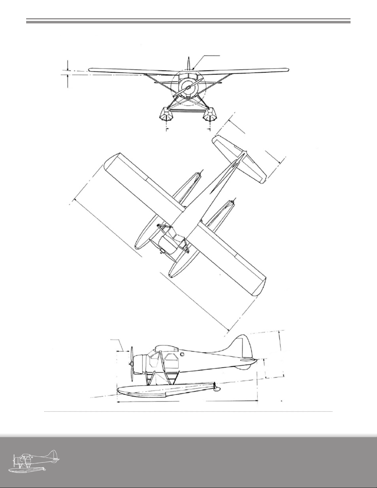
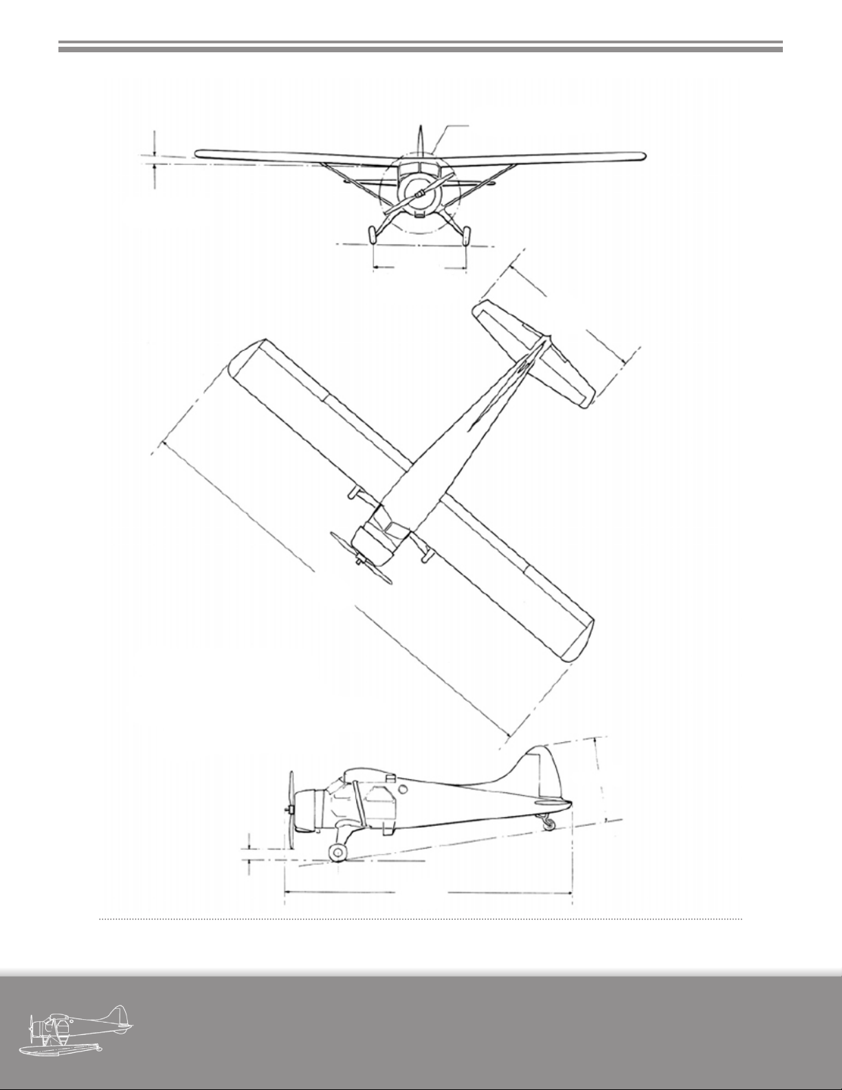
3.2 Dimensions
See Figure 3-3.
3.3 Gross Weight
See Figure 3-3.
military visualizations page
DHC-2 BEAVER
14
Page 21
SECTION 3 - DESCRIPTION OF AIRCRAFT
3.4 Engine
The aircraft is powered by a Pratt and Whitney
“Wasp Junior” R-985SB3 nine-cylinder single row radial
engine, rated at 400 BHP at 5000 ft altitude. The engine
drives a Hamilton-Standard constant-speed propeller;
crankshaft and propeller rotation being clockwise. The
supercharger is an engine-driven single-stage centrifugal type.
3.5 Engine Controls
The engine control quadrants are located on the
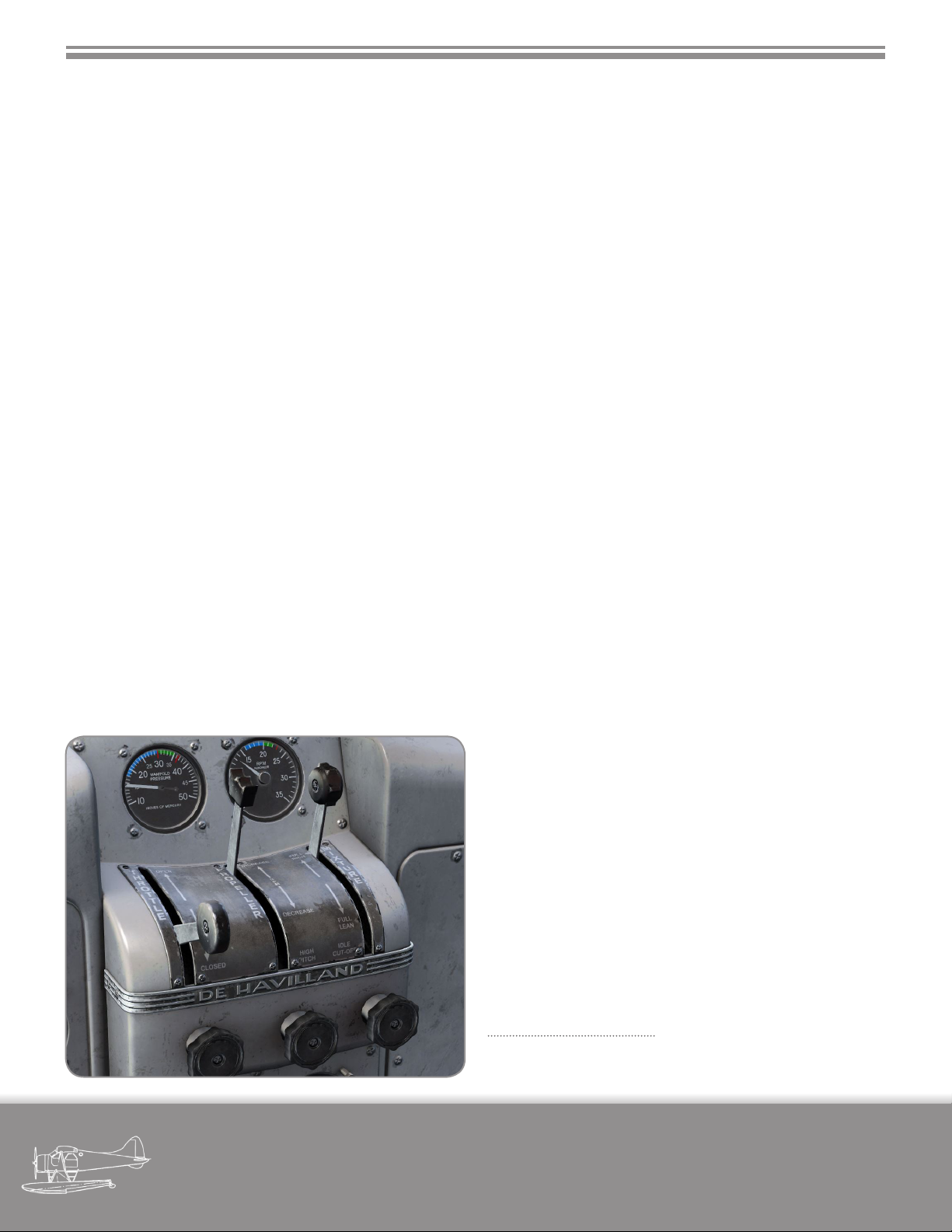
top of the pedestal. The order of controls being: THROTTLE - PROPELLER - MIXTURE as shown in Figure 3-1.
Friction control knobs, one below each control lever,
increase lever friction when rotated clockwise. (Friction
control knobs are non-functional.)
3.5.1 Throttle Lever
The throttle lever moves in a quadrant marked
OPEN and CLOSED. The lever is connected to the throttle
valve by means of push-rods and torque-tube linkage.
3.5.2 Mixture Lever
The mixture lever moves in a quadrant marked as
follows: FULL RICH - FULL LEAN - IDLE CUT OFF. The lever
is connected to the carburettor by means of push-rods
and torque-tube linkage.
3.5.3 Carburettor Heat Control Lever
The carburettor heat control lever is located below
the engine instrument panel and is cable-connected to a
gate valve in the carburettor air intake duct.
When the lever is selected up to the COLD position, cold ram air enters the carburettor through the air
intake duct.
With the lever down in the HOT position, the ram
air intake is fully closed and heated air only, from inside
a heat exchanger mu surrounding a section of the engine exhaust collector, is ducted to the carburettor.
3.5.4 Carburettor Air Induction System
The upper air induction system (Modication
2/1164) consists of an air scoop on the top right of the
engine rear cowling feeding air through a duct, at the
right side of the engine, and through a lter to the carburettor. In this installation the induction air is ltered at all
times and there is no pilot control, except during emergency operation when the lter is bypassed (Emergency
air handle for lter bypass not modelled).
3.5.5 Engine Ignition Switches
A rotary four position ignition switch, located below the ight instrument panel, is marked OFF, L, R, and
BOTH.
3.5.6 Boost Coil Switch
A boost coil switch, located on the starter panel, is
spring loaded to the OFF position.
Fi gur e 3-1 - engi ne
Co ntr ol Quad ran ts
military visualizations page
DHC-2 BEAVER
15
Page 22
SECTION 3 - DESCRIPTION OF AIRCRAFT
2 ° DIHEDRAL
PROPELLER DIA. 8 FT. 6 IN.
WING AREA 250 SQ. FT
WING LOADING 20.4 LB/SQ. FT
SPAN LOADING 2.2 LB/SQ. FT
POWER LOADING 11.3 LB/H.P.
GROSS WEIGHT SEAPLANE 5090 LBS
TRACK 9 FT 7 IN
15 FT 10 IN
48 FT 0 IN
2 FT 5 IN
10 FT 5 IN
4 FT 2 IN
32 FT 9 IN
Fi gur e 3 -2 - tH ree vi ew di men sio nal di agr am - sea plan e
military visualizations page
DHC-2 BEAVER
16
Page 23
SECTION 3 - DESCRIPTION OF AIRCRAFT
2 ° DIHEDRAL
10 FT 2 IN
TRACK UNDER
STATIC LOAD
PROPELLER DIA. 8 FT. 6 IN.
15 FT 10 IN
48 FT 0 IN
WING AREA 250 SQ. FT
WING LOADING 20.4 LB/SQ. FT
SPAN LOADING 2.2 LB/SQ. FT
POWER LOADING 11.3 LB/H.P.
GROSS WEIGHT LANDPLANE & SKIPLANE 5100 LBS
12 IN
30 FT 4 IN
Fi gur e 3 -3 - tH ree vi ew di men sio nal di agr am - lan dpla ne
9 FT 0 IN
military visualizations page
DHC-2 BEAVER
17
Page 24
SECTION 3 - DESCRIPTION OF AIRCRAFT
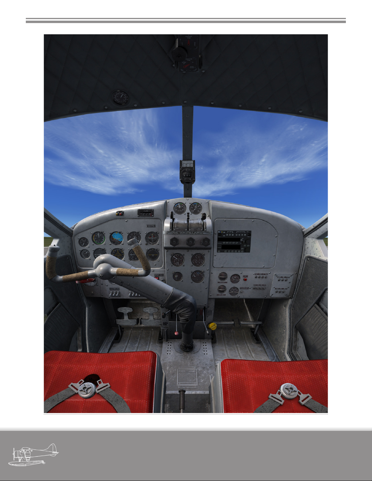
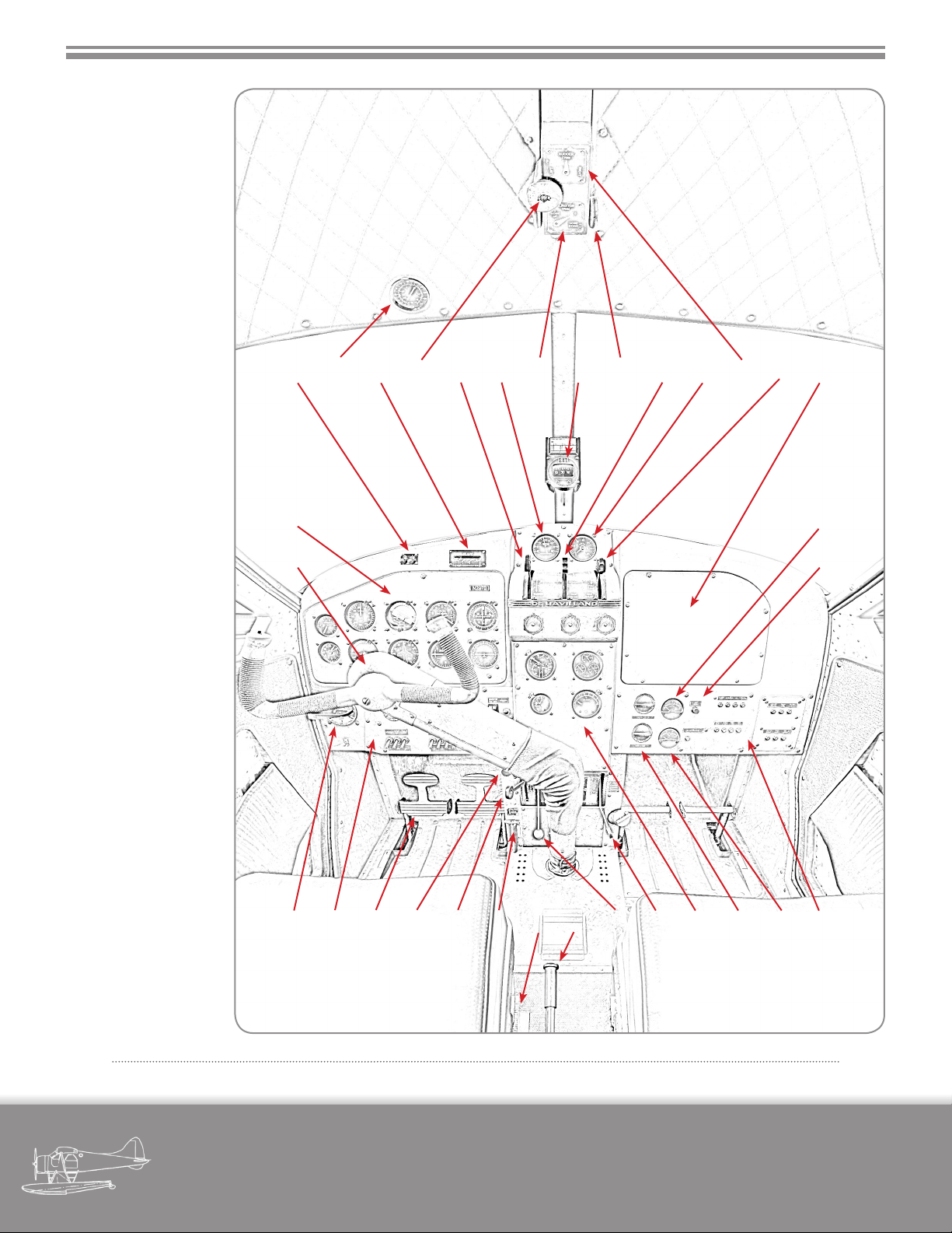
Fi gur e 3 -4 - Fl igH t Co mpar tmen t
military visualizations page
DHC-2 BEAVER
18
Page 25
SECTION 3 - DESCRIPTION OF AIRCRAFT
1. Control Column
2. Flight Instrument Panel
3. Fuel & Oil Warning Lamps
4. Outside Air Temp. Gauge
5. Flap Indicator
6. Rudder Trim Wheel
7. Throttle Lever
8. Manifold Pressure Gauge
9. Elevator Trim Indicator
10. Compass
11. Elevator Trim Wheel
12. Propeller Lever
13. Tachometer
14. Rudder Trim Indicator
15. Mixture Lever
16. Radio Panel
17. Ammeter
18. Alternator Warning Lamp
19. Circuit Breaker Panel
20. Voltmeter
21. Lighting Adjustment Dials
22. Engine Instrument Panel
23. Fuel Shutoff Lever
24. Wobble Pump
25. Flap Hydraulic Hand Pump
26. Flap Selector
27. Cabin Heat Control
28. Carburettor Air Lever
29. Parking Brake
30. Rudder Pedals
31. Electrical Switch Panel
32. Fuel Selector
3 987654 10 11 12 13 14 15 16
172
181
32 262728293031 25 24 23 22 21 20 19
Fi gur e 3 -5 - Fl igH t Co mpar tmen t, in dex ed
military visualizations page
DHC-2 BEAVER
19
Page 26

SECTION 3 - DESCRIPTION OF AIRCRAFT
When the switch is held to the BOOST COIL position, high tension electrical current is supplied to the
engine spark plugs to initiate starting. (The boost coil
switch, not always found in currently ying DHC-2’s, has
been made INOP.)
3.5.7 Primer Pump
The hand operated cylinder primer pump is on the
oor to the left of the pilot’s seat. The pump handle is
pushed down and rotated anti-clockwise to unlock and,
after use, relocked by pushing it down and rotating it
clockwise.
3.5.8 Starter
The engine in the MilViz DHC-2 is started by an
electrical direct cranking starter motor.
3.5.9 Starter Switch
The starter switch for the electrical direct cranking
start motor is located on the electrical switch panel below the ight instrument panel.
3.6.1 Propeller Lever
The propeller lever is located to the right of the
throttle lever in the engine controls quadrant on the
top of the pedestal and slides in a gate marked RPM, DECREASE, and INCREASE. It is connected by a push/pull
rod linkage to the propeller governor.
The governor retains the selected rpm constantly,
within the operating range of the propeller, regardless of
variations in air loads or ight attitudes.
When INCREASE RPM is selected the governor directs oil from its own engine driven pump to the propeller, at pressure, which hydraulically moves the propeller
blades, in opposition to the counterweight, to lower angles.
When DECREASE RPM is selected the governor allows oil from the propeller to return to the engine sump
and the counterweights move the blades to higher angles.
3.7 Oil System
3.5.10 Engine Instruments
Conventional engine instruments are mounted
on panels above and below the engine controls quadrant on the pedestal. The engine instruments consist of
Tachometer (above pedestal), Manifold Pressure Gauge
(above pedestal), Cylinder Head Temperature Gauge,
Carburettor Mixture Temperature Gauge, combined Oil
and Fuel Pressure and Oil Temperature Gauge (all below
pedestal).
3.6 Propeller
The engine drives a Hamilton-Standard two-bladed 8 ft 6 ins. diameter constant speed, counterweight
type propeller having a pitch range from 11.5° to 24°.
(The MilViz DHC-2 may be optionally congured and
own with a three-bladed Hartzell propeller through the
MVAMS utility.)
The oil tank is located aft of the rewall and is serviced from inside the cockpit through a ller at the base
of the pedestal. the capacity is 5 1/4 IMPERIAL GAL. (1
gal. air space), the air space may be reduced during oil
dilution. Oil returned from the engine passes through a
line to a combined oil temperature valve and cooler.
3.7.1 Oil Dilution
When a start in cold weather is anticipated, the oil
may be diluted with gasoline before stopping the engine. (Dilution ability is not available in this release and the
corresponding dilution switch is not present.)
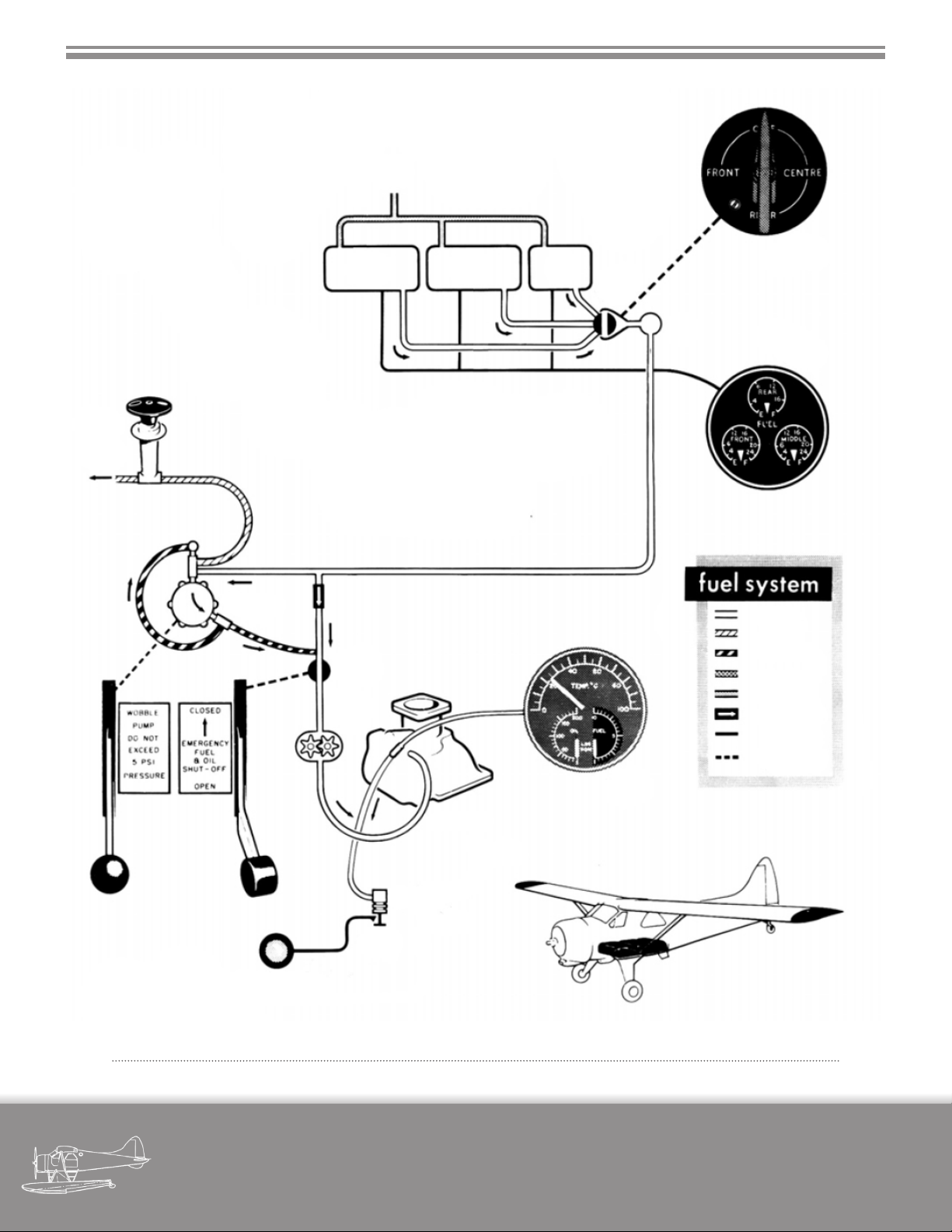
3.8 Fuel System
Fuel is contained in three tanks under the cabin oor which are used separately. They are serviced
through three ller necks in a ller compartment pro-
military visualizations page
DHC-2 BEAVER
20
Page 27
SECTION 3 - DESCRIPTION OF AIRCRAFT
VENT
FRONT
TANK
ENGINE
PRIMER
TO
ENGINE
CENTER
TANK
REAR
TANK
FUEL
SELECTOR
SELECTOR
VALVE
FUEL
QUANTITY
GAGE
WOBBLE
PUMP
ENGINE
DRIVEN
FUEL
PUMP
FUEL PRESSURE
WARNING LIGHT
EMERG
SHUTOFF
VALVE
FUEL
PRESSURE
SWITCH
CARBURETOR
FUEL
PRESSURE
GAGE
SUPPLY
PRIME
EMERGENCY
AIR PRESSURE
VENT
CHECK VALVE
ELECTRICAL
ACTUATION
MECHANICAL
ACTUATION
Fi gur e 3 -6 - Fu el sys tem dia gram
military visualizations page
DHC-2 BEAVER
21
Page 28

SECTION 3 - DESCRIPTION OF AIRCRAFT
tected by a hinged door on the forward left-hand side of
the fuselage, adjacent to the cockpit door.
3.8.1 Fuel Capacities
Front Tank 29 Imp. (35 U.S.) gal.
Centre Tank 29 Imp. (35 U.S.) gal.
Rear Tank 21 Imp. (25 U.S.) gal.
Total without 79 Imp.(95 U.S.) gal.
wing tip tanks
3.9 Fuel System Controls
3.9.1 Fuel Selector
Fuel is supplied from any one of the three fuel
tanks by selecting FRONT TANK, CENTRE TANK or REAR
TANK on the fuel selector, located to the left of the electrical switch panel, under the ight instrument panel.
3.9.4 Fuel and Oil Emergency Shut-O Lever
The emergency shut-o lever, on the right side
of the pedestal, below the engine instrument panel, is
normally wirelocked in the down position. When pulled
sharply up to break the wire lock, and moved to the
closed position, it cuts o the supply of both fuel and
oil to the engine. After use it can be returned to its down
position for normal operation but should be wirelocked
as soon as possible to prevent inadvertent operation.
3.9.5 Fuel Contents Gauge
A triple indicator fuel contents gauge, located on
the right side of the engine instrument panel, is graduated in Imperial gallons.
3.9.6 Fuel Pressure Gauge
A combined fuel pressure, oil pressure and oil temperature gauge is located on the left side of the engine
instrument panel.
3.9.2 Fuel Booster Pump
To assist the engine driven fuel pump, a booster
pump may be incorporated into the fuel system.
The use of the booster pump should normally be
conned to engine starting and ight at high altitude,
when its operation would help to prevent fuel vapour
locks.
3.9.3 Fuel Wobble Pump
A fuel wobble pump lever, below the engine instrument panel on the pedestal, is used to build up the
fuel pressure to 5 psi, for starting the engine.
In an emergency the fuel pressure can be maintained by the wobble pump should the engine driven
pump fail.
3.9.7 Fuel Pressure Warning Light
A red warning light, which lights up when the fuel
pressure drops to 3 psi, is positioned above the ight instrument panel.
3.10 Electrical System
Electrical DC energy is supplied by a 50 amp 28-30
volt alternator rectied for direct current use in conjunction with a 24 volt 17 amp/hr. battery. The alternator is
regulated by a voltage regulator. A reverse-current relay
is used to protect the alternator when it is not charging.
The alternator is selected by a alternator switch on
the electrical switch panel to the left of the pedestal.
The battery is stowed in a compartment on the left
side of the fuselage, aft of the cabin door, and is accessible through a hinged panel on the outside of the aircraft.
military visualizations page
DHC-2 BEAVER
22
Page 29
SECTION 3 - DESCRIPTION OF AIRCRAFT
3.10.1 Electrically Operated Equipment
The following equipment and controls are oper-
ated by the electrical system:
Starter
Oil dilution system
Booster pump
Engine indicators
Fuel contents gauge
Interior lights
Navigation lights
Landing light
Fuel pressure warning light
Electronic equipment
Pitot head heater
3.10.2 Alternator Switch
The alternator switch, located on the electrical
switch panel, is of the single pole, single throw type.
3.10.3 Battery Master Switch
The battery master switch is located in the right-
hand upper corner of the electrical switch panel. It is of
the double pole, single throw type and interrupts the
battery output to the electrical system.
The circuit controlling the cabin lights are independent of the master switch.
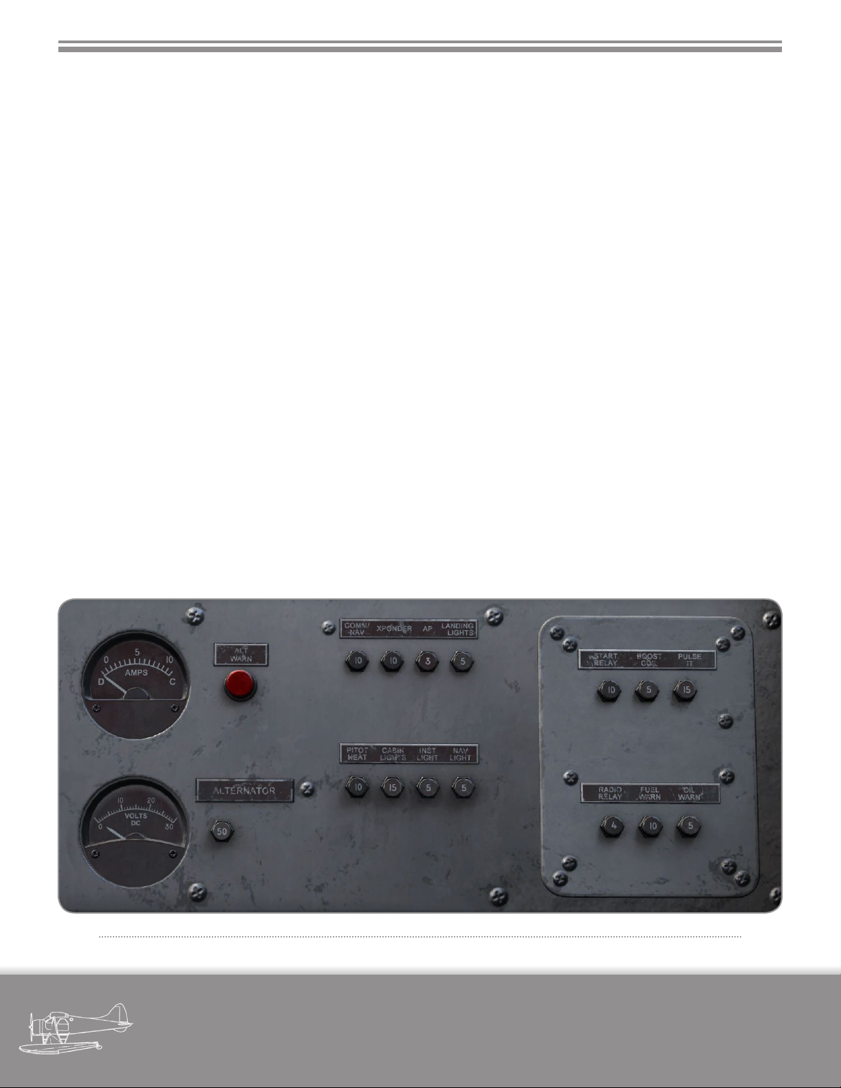
3.10.4 Electrical System Indicators
A left-zero ammeter, located to the left of the circuit breaker panel, indicates the load on the alternator
supply. A warning lamp is located to the right of the ammeter to indicate a load greater than the alternator supply.
A voltmeter is located below the ammeter. The
voltage of the alternator supply is indicated. When the
alternator is not operating, the battery voltage only will
be indicated.
3.10.5 Circuit Breakers
A circuit breaker panel is located below the radio
panel, to the right of the pedestal. Circuit breakers are
provided for the isolation and protection of the installed
electrical equipment.
Fi gur e 3 -7 - el eCt riC al s y ste m i n diC ator s & Cir Cui t Br eak er pa nel
military visualizations page
DHC-2 BEAVER
23
Page 30
SECTION 3 - DESCRIPTION OF AIRCRAFT
3.11 Flight Control System
The control surfaces are conventionally operated
by a control column and rudder pedals. The upper portion of the control column carrying the handwheel, may
be “thrown-over” for use by a copilot in conjunction with
the rudder pedals on the right side of the cockpit. The
ailerons are dierentially rigged to give a larger upward
then downward displacement and are drooped when
the wing aps are lowered through the rst 15°.
Trim tabs, adjustable in ight, are tted to the elevator and rudder.
3.11.1 Control Column Throwover and Lock
The control column can be thrown over during
level cruising ight without disturbing the balance of
the aircraft by grasping the upper portion of the column
and allowing the handwheel free movement as the upper portion is “thrown-over” for use by the copilot. (The
control column may be manipulated with the mouse scroll
wheel while the mouse is positioned over the handwheel.)
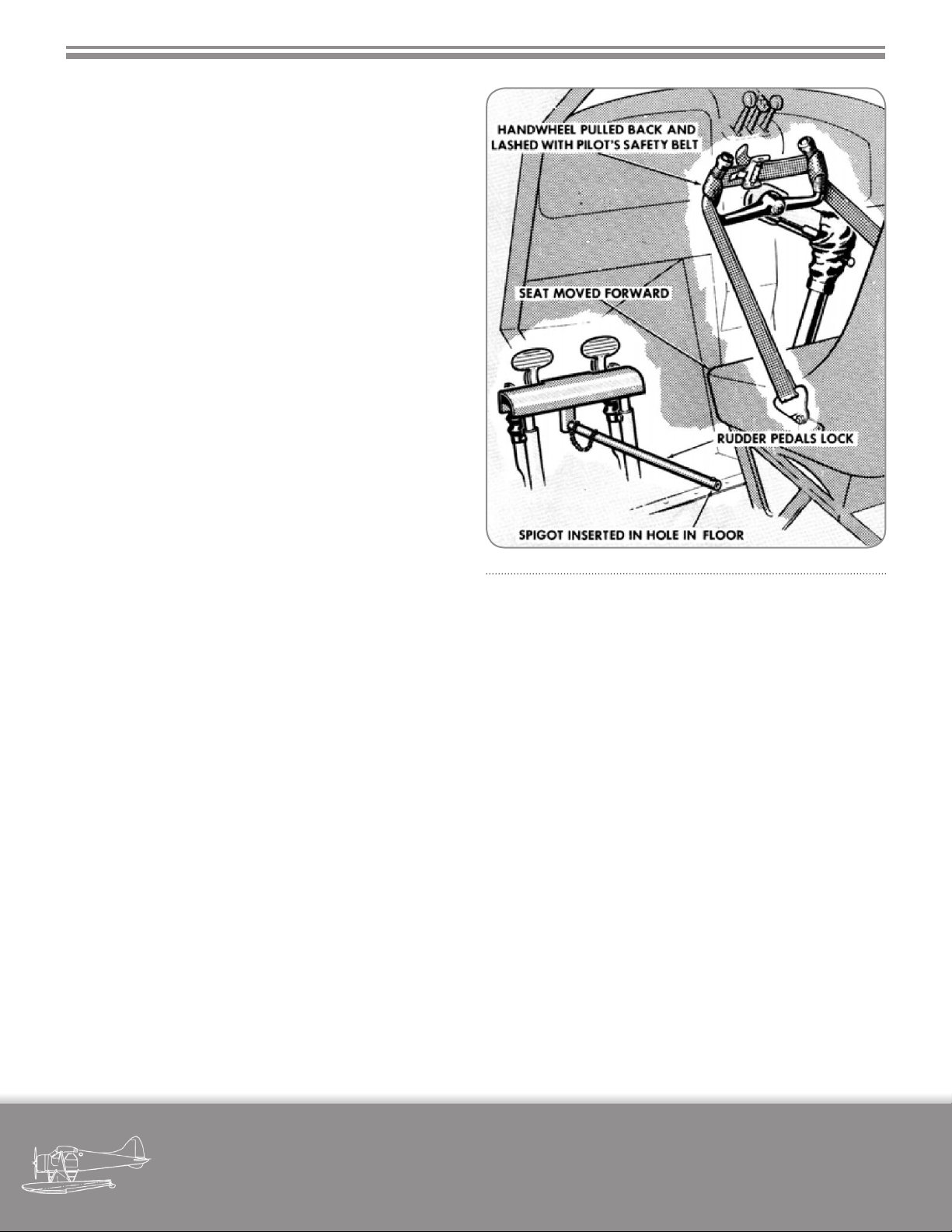
Fi gur e 3 -8 - Fl igH t Co ntr ol lo Cks
A lock plunger at the hinge point of the control
column locks the hinged upper portion of the column in
position. (The lock plunger is modelled but has no applica-
ble function in this release.)
3.11.2 Elevator Trim
The elevator trim is adjusted by twin handwheels
on the cockpit roof, operating in the natural sense. A
pointer and scale, between the handwheels, marked
NOSE UP, NOSE DOWN, indicate the the direction and
degree of trim applied.
3.11.3 Rudder Trim
The rudder trim is adjusted by a handwheel on the
cockpit roof, just aft of the elevator trim handwheels. A
pointer and scale, marked LEFT and RIGHT indicate the
direction and degree of trim applied.
3.11.4 Control Locks
The control column and handwheel are locked by
strapping them to the pilot’s seat with the safety belt.
The rudder pedals are locked by a pedal lock which,
when not in use, is stowed in the baggage compartment
behind the cabin rear partition.
To lock the pedals, the channel portion of the lock
must be tted over the pedals and the spigots at the end
of the lock-rod, which is attached to the channel portion
by a chain, must be inserted into a hole in the channel
and in a corresponding hole in the cockpit oor, forward
of the pilot’s seat. (The control locks are automatically set
in place when the reds are shown or removed.)
3.12 Wing Flaps
The wing aps are of the slotted type and extend
from the wing roots to the inboard ends of the ailerons
which also droop in conjunction with the ap move-
military visualizations page
DHC-2 BEAVER
24
Page 31

SECTION 3 - DESCRIPTION OF AIRCRAFT
ment. The aps are operated by an actuating cylinder
located in the fuselage at the left-hand wing root. Hydraulic uid is supplied to the actuating cylinder by a
handpump, under the pilot’s seat. This handpump has
an integral reservoir, a selector valve, and a relief valve.
The relief valve is set at 1000 psi.
3.12.1 Wing Flaps Hand Pump Lever
The wing ap hand pump lever is at the right-hand
side of the pilot’s seat and is operated in a fore-and-aft
direction.
3.12.2 Wing Flaps Selector Lever
The wing aps selector lever is located on the right
hand side of the pilot’s seat. It has two marked positions,
UP and DOWN. Intermediate positions of the wing aps
are selected by moving the selector lever to UP or DOWN
then pumping the wing aps with the hand pump lever
to the desired position, as shown on the wing aps indicator.
WARNING
If the aps are in any lowered position, it is
essential that the selector lever is retained in
the DOWN position. When the aps are retracted, the selector lever must be retained
in the UP position. Once the selector lever is
set to DOWN and the aps are pumped to
the desired position, the selector lever must
not be moved until it is desired to change
the ap position.
3.12.3 Wing Flaps Indicator
A wing aps position indicator is situated above
the ight instrument panel. It is marked FULL FLAP,
LANDING, TAKEOFF, CLIMB and CRUISE. FULL FLAP is
only required for emergency landing in very restricted
areas.
units are replaced by two oats which are attached to
the fuselage by struts.
For winter operations, the main wheels and tail-
wheel may be replaced by skis.
3.13.1 Tailwheel Steering
The tailwheel is steerable by operation of the rudder pedals, for 25° each side of the longitudinal centre
line of the aircraft.
3.13.2 Brake System
The main landing gear wheels are each tted with
a hydraulic brake unit which is individually actuated
through an independent hydraulic line and brake master cylinder. Each brake master cylinder has an integral
uid reservoir and is connected by an adjustable linkage
to its relative toe pedal. Depression of the toe pedal operates the piston in the relevant master cylinder which
causes pressure to be applied, through exible and rigid
brake lines and a brake valve, to the wheel brake unit
concerned. A parking brake is incorporated in the brake
system.
Operation of the parking brake handle in the cockpit locks the brake units on the “on” position.
3.13.3 Toe Pedals
Pressure on the toe pedals, which are the upper
portions of the rudder pedals, actuates the pistons in
the master cylinders and displaces hydraulic uid into
the brake units where the shoes are applied to the brake
discs. The toe pedals are adjustable relative to the rudder
pedals by adjusting the lengths of the master cylinder
connecting rods.
The removable rudder pedals for the copilot are
not connected to the brake system.
3.13 Landing Gear System
The main wheel units and the tailwheel unit are
not retractable. For water based operations the wheel
military visualizations page
DHC-2 BEAVER
25
Page 32

SECTION 3 - DESCRIPTION OF AIRCRAFT
3.13.4 Parking Brake
When the parking brake handle is pulled, pressurized uid is trapped in the lower part of the brake system
and locks the brake units.
If the brake toe pedals are operated are operated
while the parking brake is set, hydraulic pressure greater
than that existing in the system below the parking valves
is created in the master cylinder and this additional pressure will push back the locking plunger of the parking
valve and disengage the parking brake.
3.14 Instruments
A shock-mounted ight instrument panel is provided for the pilot and incorporates an altimeter, turnand-bank indicator, rate-of-climb indicator, airspeed
indicator, directional gyro, articial horizon, course deviation indicator and ADF bearing indicator.
3.14.1 Pitot Static Operated Instruments
The airspeed indicator, altimeter, and the rate-ofclimb indicator, are operated by the pitot static system.
The static opening is incorporated in the left-hand side
of the rear fuselage.
3.14.4 Articial Horizon
The articial horizon is powered by the vacuum
system. Its horizon bar gives a dive, climb and angle of
bank indication. A knob at the bottom of the instrument
dial permits adjustment of the instrument to any foreand-aft attitude of the airplane within limits of plus or
minus 7°.
A caging knob on the instrument erects the gyro
and locks the horizon bar in the horizontal position. This
knob must be in the uncaged position before take-o to
insure proper indications from the instrument.
The operating limits are set to permit 70° climbs
and glides, and 100° right or left banks before the limit
stops are reached. If exceeded, the caging knob provides
a rapid means for resetting the articial horizon.
3.14.5 Magnetic Compass
The magnetic compass is mounted on a bracket
attached to the windshield center post. A compass deviation card is mounted above the compass.
3.15 Emergency Equipment
3.14.2 Vacuum Operated Instruments
The directional gyro, articial horizon and turnand-bank indicator, are operated by the vacuum system.
A vacuum gauge located on the far left of the ight instrument panel indicates the vacuum in In.Hg. being applied to the instruments.
3.14.3 Outside Air Temperature Gauge
The outside air temperature gauge is located in
the cockpit roof. It is of the direct-reading bulb type and
the dial is graduated in both Fahrenheit and Centigrade
scales.
military visualizations page
3.15.1 Hand Operated Fire Extinguisher
Hand operated re extinguishers are stowed in
quick release clips on the oor, in front of the pilot’s and
copilot’s seats.
3.16 Seating Arrangement
The seating arrangement, with the exception of
the pilot’s seat, varies with the internal loading requirements of the ight.
3.16.1 Pilot’s Seat
The pilot’s seat is tted with a lap type safety belt.
The seat cushion has grab-lines and may be used as a
DHC-2 BEAVER
26
Page 33
SECTION 3 - DESCRIPTION OF AIRCRAFT
life-preserver when abandoning the aircraft in or over
water.
3.16.2 Passenger Seats
All passenger seats, including the copilot’s seat,
are tted with lap type safety belts. All seats are removable. (The passenger seats aft of the pilot’s and copilot’s
seats are automatically removed in the cargo version of the
MilViz DHC-2.)
3.17 Heating System
Hot air for heating the interior of the cabin is supplied by ram air passing through a heat exchanger tube
in the engine exhaust system. From a four-way outlet at
the centre of the cockpit oor, the heated air is ducted
to the pilot’s seat and front passengers feet and to two
outlet grills in the cabin oor.
A heated air outlet at the top of the instrument
panel permits defrosting of the pilot’s windshield. A second outlet can be installed for the copilot’s windshield.
All hot air outlets are controlled simultaneously by
a push-pull control, on the base of the pedestal which
alternates between fully ON in it’s up position and fully
OFF.
3.18 Ventilation System
Two ventilation louvers, one of each side of the
cockpit roof, to the left and right of the pilot and copilot,
supply ram air to the cabin from screened openings in
the leading edge of each wing root.
An exhaust type circular grill and shutter ventilator
in the cabin roof exhausts air from the cabin. Necessary
suction is provided by a rearward facing air scoop on top
of the fuselage.
HYDRAULIC RESERVOIR FLUID
DO NOT FILL ABOVE 3/4 IN.
FROM TOP, OR OVERSPILLING
WILL OCCUR THROUGH VENT
HOLE IN DIPSTICK
OIL TANK FILLER
IN COCKPIT
LONG RANGE FUEL TANK
FILLER NOT INSTALLED
FILLERS FOR FRONT CENTER
AND REAR FUEL TANKS
CENTER FUEL TANK
FRONT FUEL TANK
EXTERNAL LONG RANGE
FUEL TANK NOT INSTALLED
GROUND SOCKET
STATIC PORT
REAR FUEL TANK
TIRE PRESSURES:
MAIN WHEELS 25 PSI
TAILWHEEL 35 PSI
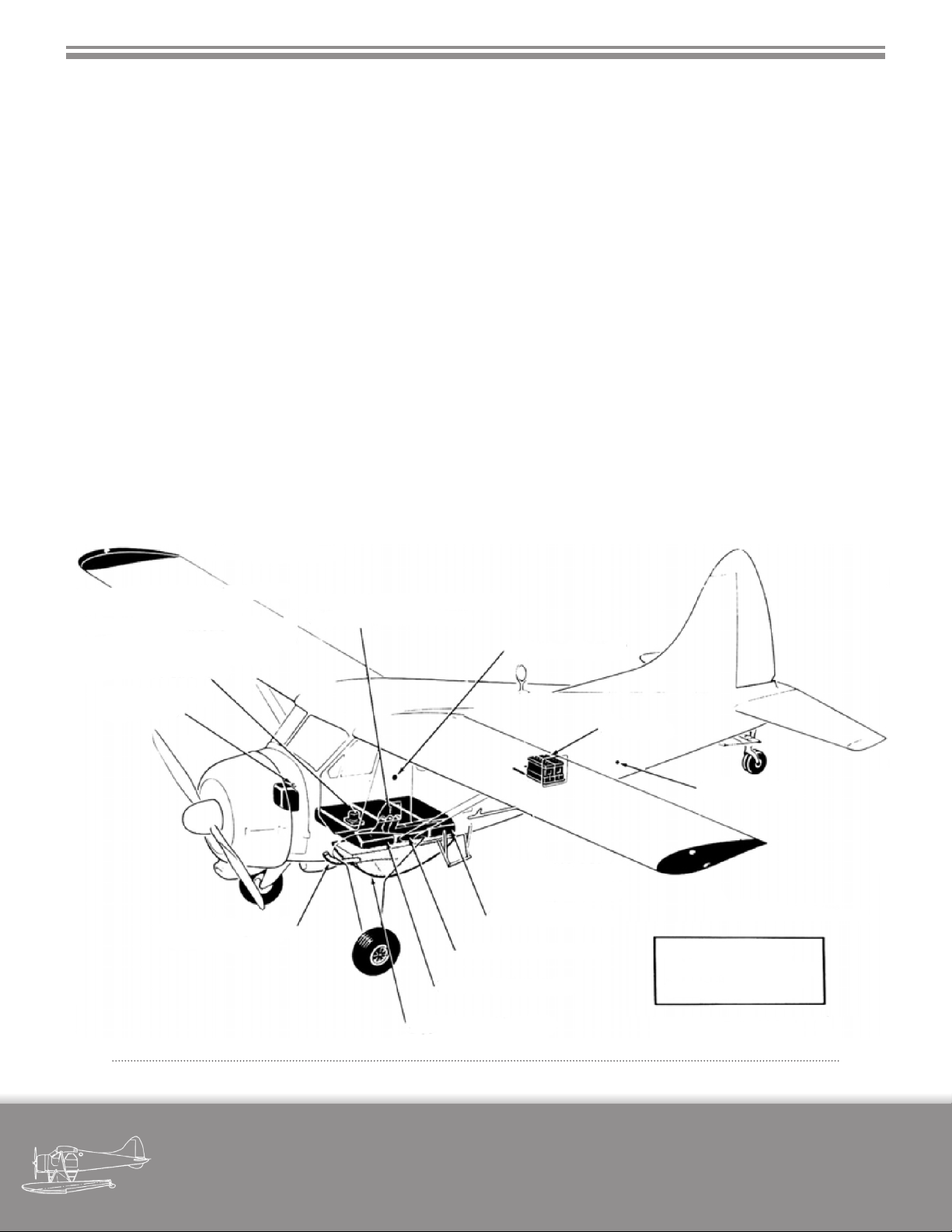
Fi gur e 3 -9 - ro uti ne servi Cin g p o int s
military visualizations page
DHC-2 BEAVER
27
Page 34
4. NORMAL PROCEDURES
In keeping with the previous section, we’ve chosen to include here some of the text from the portion of the original ight manual that covers normal procedures.
However, the original text has only been kept where it
does not conict with the actual or intended behaviour
of the MilViz DHC-2. In this manner, although this section
reads closely like the original ight manual, it fully represents the simulated aircraft, rather than the real DHC-2.
With that said, we may have included references to nonsimulated actions or aircraft behaviour where we felt it
might be of interest, with notations made where it might
not be obvious that such references would not apply to
the aircraft within the simulator.
Our overall goal is to let the section give an overview on
how to operate the MilViz DHC-2, while also giving a bit
of insight on the day-to-day operation of the real aircraft.
Starting at the pilot’s cockpit,
make the following checks:
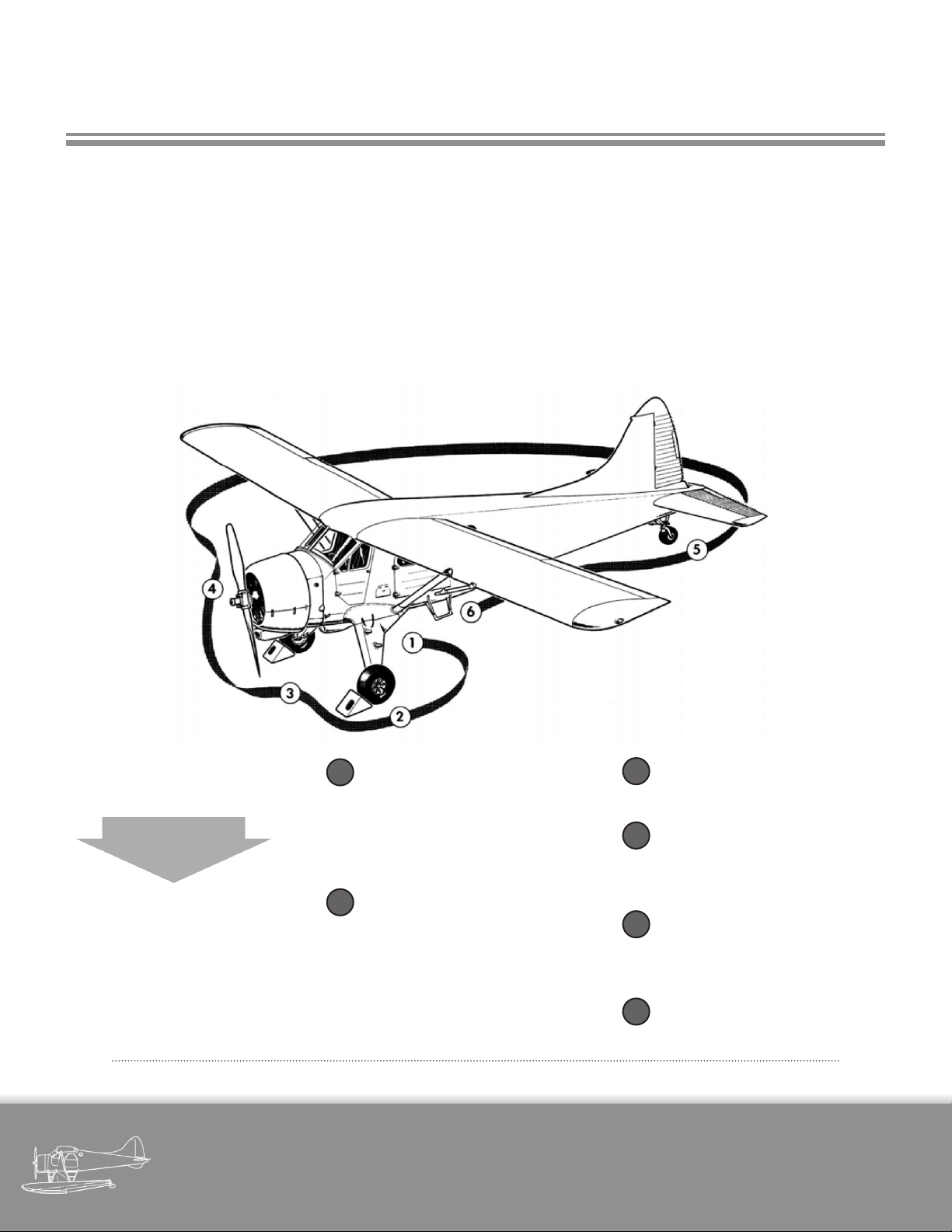
While making exterior inspection, check all surfaces for cracks,
distortion, loose rivets and indication of damage. Check all access doors for security. Check
surfaces and hinges of all ight
control surfaces.
Fi gur e 4 -1 - ex ter ior in spe Ct ion di agr am
military visualizations page
DHC-2 BEAVER
Check security of fuel ller caps
1
and access panel. Check that the
aircraft has been serviced with
required quantities of fuel, oil
and hydraulic uid.
Check that wheels are chocked.
2
Check security of landing gear,
fairings, tires for cuts, bruises
and slippage. Check tire pressures and wheel brakes hose
and pipes for oil leaks.
Check that carburettor and oil
3
cooler intakes are clear.
4
Check propeller for nicks and oil
leaks. Check cowl and panels for
dents, scratches and security.
Check tailwheel tire for cuts,
5
bruises and slippage. Check tire
pressure.
Check that pitot head cover is
6
removed.
28
Page 35

SECTION 4 - NORMAL PROCEDURES
4.1 BEFORE ENTERING AIRCRAFT
(d) Flashlight - on board. (Not applicable.)
Carry out an EXTERNAL INSPECTION of the air-
plane as detailed in Figure 4-1.
Also check storage of cargo and baggage and de-
termine load distribution and CG position.
4.2 ON ENTERING AIRCRAFT
Check the following:
(a) Ignition - OFF.
(b) Parking Brake - set.
(c) Controls - unlocked.
(d) Controls for - free, correct and full movement.
(e) Adjust pilots seat. (Not applicable.)
4.3 BEFORE STARTING ENGINE
Make the following checks:
(a) Propeller area - clear.
(b) All switches - OFF.
(c) Throttle lever - 1/4 to 1/2 in. OPEN.
(d) Propeller lever fully DECREASE RPM.
(e) Mixture lever IDLE CUT-OFF.
(f) Carburettor hot air lever - COLD.
(g) Use starter to turn propeller to make sure that an
excessive amount of oil is not trapped in the lower cylinders, forming a hydraulic lock. (Possibility of hydraulic lock
is not available in this release.)
(f) Trims - as required.
(g) All switches - OFF.
(h) Battery master switch ON.
(j) Circuit breakers - check.
(j) Fuel quantities - check.
(k) Altimeter - set.
When night ying is anticipated, make the following
checks, possibly with the help of an outside observer:
(a) Landing light.
(b) Navigation lights.
(c) Check panel lights, interior lights.
4.4 STARTING ENGINE
4.4.1 NORMAL ENGINE START
(a) Propeller area - clear.
(b) Battery master switch - ON.
(c) Fuel and oil emergency cut-o lever - OPEN.
(d) Fuel selector to fullest tank.
(e) Mixture lever - FULL RICH.
(f) Throttle lever - 1/4 to 1/2 in. OPEN.
(g) Buildup fuel pressure with wobble pump to maximum 5 psi.
military visualizations page
DHC-2 BEAVER
29
Page 36

SECTION 4 - NORMAL PROCEDURES
(h) Prime 4 strokes.
(Note: Priming 4 strokes is recommended if the engine is
at ISA or lower. A warm engine will only require 3 strokes,
while very cold temperatures will require 6 priming strokes.
It is also possible to try and start a poorly primed engine by
‘throttle pumping’ twice; that is, to move the throttle fully
forward and back two times. )
(j) Ignition switch - BOTH.
(k) Starter switch to STARTER position.
As soon as the engine res:
(l) Ensure starter switch in OFF position.
CAUTION
1. As soon as engine res, throttle back to
about 500 to 800 rpm.
2. Do not pump throttle to catch a “dying”
engine.
3. If oil pressure does not register on gauge
within 30 seconds, stop engine and investigate.
(m) As soon as oil pressure reaches 50 psi steady indication, select propeller lever to full INCREASE RPM position.
(a) Ignition - OFF.
(b) Mixture lever - IDLE CUT OFF.
(c) Throttle lever fully open.
(d) Clear excess fuel from induction system by using
the starter to turn the propeller through 3 to 5 revolutions.
(e) Repeat normal starting procedure.
4.5 ENGINE WARMUP
(a) Throttle to give 1000 rpm.
(b) Move propeller lever fully forward to INCREASE
RPM, as soon as oil pressure reaches 50 psi.
(c) After oil temperature has reached 100°F (40°C), adjust to smoothest engine speed between 1000 to 1400
rpm. Mixture lever FULL RICH.
(d) Select propeller lever to coarser pitch at 1000 rpm,
to circulate the oil in the constant speed unit and propeller cylinder, then return to INCREASE RPM.
(e) Check oil pressure, fuel pressure and temperature.
(n) Alternator switch - ON.
(o) Check that the alternator warning light is extinguished.
4.4.2 FAILURE IN STARTING
Flooded Engine
Indication of engine being ooded is given by an increase in propeller rotation speed with an engine close
to catching but failing, followed by the short production
of white smoke.
military visualizations page
DHC-2 BEAVER
(f) Tank feeds - check by rotating fuel selector to each
tank.
4.6 ENGINE GROUND TESTS
The engine oil inlet temperature should be above
100°F (40°C) yet never rise above 200°F (90°C). Cylinder
head temperature must not exceed 450°F (230°C).
Head aircraft into wind
(a) Parking brake ON, control column fully back.
(b) Fuel selector to fullest tank.
30
Page 37

SECTION 4 - NORMAL PROCEDURES
(c) Propeller lever full INCREASE RPM
(d) Set throttle lever to give 1750 rpm.
(e) Select magneto switch to “L”. Return switch to
“BOTH” to allow engine speed to stabilize itself before
switching to “R”. Return to “BOTH”.
(c) Watch oil and cylinder temperatures. If necessary,
run engine at higher rpm to provide additional cooling
during taxiing.
(d) Make brake test as soon as aircraft starts moving.
(e) Operate rudder pedals to steer aeroplane by
means of steerable tailwheel (25° to each side).
The drop in rpm should not exceed 100 rpm; it is
normally in the region of 50 to 75 rpm. (In cold weather
keep the carburettor mixture temperature at 40°F (4°C)
for this check).
(f) If magneto drop is more than 100 rpm recheck at
aerodrome pressure.
(g) Set throttle lever to give 600 rpm.
(h) Momentarily turn ignition switch OFF. The engine
should stop ring completely.
(j) Open throttle until manifold pressure is equal to
aerodrome pressure.
(k) Check rpm 2100 plus or minus 20 approximately.
(l) Check oil, fuel and vacuum pressures, cylinder
head and oil temperature within ranges.
(f) Run engine at 1200 - 1400 rpm when aircraft is
stopped during taxiing, to prevent spark plug fouling
and to create a propeller blast for engine cooling.
WARNING
While on the ground, avoid prolonged engine running above 1400 rpm, particularly
in hot weather, to prevent overheating of
the installation.
4.8 TAKEOFF CHECK
(a) All doors and windows closed.
(b) Elevator to meet CG requirements.
(c) Mixture lever - FULL RICH.
(d) Propeller lever - INCREASE RPM.
(m) Retard throttle to give 1600 rpm.
(n) Move propeller lever to HIGH PITCH then return to
full INCREASE RPM position. Note recover of rpm to 1600
rpm.
4.7 TAXIING
(a) Flaps at CRUISE POSITION.
(b) Propeller lever - full INCREASE RPM.
military visualizations page
DHC-2 BEAVER
(e) Fuel selector to desired tank position.
(f) Flaps - TAKE-OFF position.
(g) Articial horizon - set.
(h) Pitot heat ON if necessary in cold weather or when
icing conditions are anticipated.
(j) Carburettor heat - COLD.
31
Page 38

SECTION 4 - NORMAL PROCEDURES
4.9 TAKEOFF
(a) Make sure cylinder head temperature is below
450°F (230°C).
(b) Adjust throttle lever friction knob. (Not applicable)
(c) Line up on take-o runway.
(d) Open the throttle smoothly to maximum permissible take-o power. See Figure 6-1.
(e) Anticipate tendency of aircraft to swing to the left.
(f) Allow aircraft to y itself o at 55 to 65 mph, in a
tail down attitude and climb at 65 mph.
(g) As soon as safe height has been attained, reduce
power to 33.5 In.Hg. and 2200 rpm if the aircraft is fully
loaded, or 30 In.Hg. and 2000 rpm for normal weight.
Keep cylinder head temperature within limits
shown on gauge. Low rpm at High Manifold Pressure
helps to maintain climbing mixture strength and materially assists engine and oil cooling.
4.11 CRUISE
For continuous cruise, use Maximum Weak Mix-
ture Power or less, taking the following steps:
(a) Flaps to “Cruise”.
(b) Throttle back to 29.7 In.Hg. or less Manifold Pressure.
(c) Propeller lever to give 2000 rpm or less.
(d) Mixture lever set to rich of peak. Carburettor mixture temperature 40°F (4°C).
(h) Slowly increase airspeed to 80 mph and retrim.
(j) At altitude of 500 ft. - aps to CLIMB and retrim.
4.10 CLIMB
Best rate of climb is obtained using Maximum
Continuous Power (2200 rpm, 33.5 In.Hg.). Speed for best
rate of climb is 95 mph IAS; speed for best angle of climb
is 80 mph IAS.
Where circumstances warrant, Maximum Continuous Power may be used giving rates of climb as stated in
paragraph 6.10.1.
However, the engine manufacturer recommends,
for reduced engine wear, that 2000 rpm and 30 In.Hg.
be used. The rates of climb will then be 540 fpm for the
landplane, 460 fpm for the seaplane.
(e) Keep cylinder head temperature and oil inlet temperature within limits shown on gauge.
For Cruising power reduced below that obtained at maximum weak mixture use settings in Cruise Power Chart
in Appendix.
4.11.1 FUEL MANAGEMENT
For favourable CG travel, without long range tanks:
(a) Empty rear tank rst, if aircraft is fully loaded, in order to move CG progressively forward.
4.11.2 AIRSPEED CORRECTION
To correct indicated airspeed to calibrated air-
speed:
Refer to the Cruise Power Chart in Appendix for
recommended settings.
military visualizations page
DHC-2 BEAVER
Subtract 5 mph from all indicated cruising speeds.
32
Page 39

SECTION 4 - NORMAL PROCEDURES
Subtract 5 mph from the indicted airspeed when
aps in DOWN position.
4.11.3 WEAK MIXTURE OPERATION
Refer to Section 4.11.
4.12 DESCENT
(a) Reduce airspeed and power as required.
(b) Fuel selector to fullest tank.
4.14 LANDING
(a) Trim as required.
(b) Increase power to decrease rate of descent.
NOTE
With aps at landing, the “Power-O” approach produces a marked nose down attitude.
(c) Pull back gently on the control column for threepoint touch-down.
(c) Instruments in correct ranges.
4.13 APPROACH
(a) Reduce airspeed to 90 mph IAS.
(b) Propeller lever to INCREASE rpm.
(c) Mixture lever - FULL RICH.
(d) Flaps to LANDING or as desired.
(e) Maintain a normal approach airspeed of 80 mph
IAS. (Rate of descent will be approximately 1000 ft. per
min.).
NOTE
Open throttle several times during approach to clear engine and to prevent too
rapid engine cooling.
NOTE
When carburettor heat is used during approach, select “COLD” late on the nal approach. This is to insure that full power will
be available in case of a baulked landing.
(d) There is no tendency to swing after touchdown except in crosswinds.
NOTE
In normal stalled landing the tailwheel will
touch rst, when landing without ap.
(e) After touch-down hold control column fully back.
(f) Use rudder and steerable tailwheel to maintain
straight path.
(g) Apply wheel brakes, as necessary, to control landing run.
4.14.1 MINIMUM RUN LANDING
Minimum run landings may be necessary under
extraordinary circumstances.
Pilots familiar with the aircraft and experienced
in short landing technique may perform minimum run
landings by using full ap and reducing the airspeed on
the nal approach to 65 - 68 mph and maintaining that
speed to the point of are-out.
military visualizations page
DHC-2 BEAVER
33
Page 40

SECTION 4 - NORMAL PROCEDURES
4.14.2 CROSSWIND LANDING
The lateral component of wind velocity at and below which it is safe to land is not more than 10 mph at 90°
for landplane, skiplane and seaplane.
4.14.3 NIGHT LANDING
At night a “Power On” landing is recommended so
that a go-around is facilitated.
4.14.4 SEAPLANE LANDING
(a) Use the same procedures as for landplane.
(b) Do not lower water rudders until aircraft has
stopped planing.
4.15 GOAROUND AND BAULKED LANDING
Decide early in approach to go around, using pro-
cedure as follows:
(a) Open throttle lever slowly to full take-o power.
(b) Keep nose down, re-trimming if necessary, to
maintain normal ap down airspeeds - 65 mps for TAKEOFF ap, 75 - 90 mph for CLIMB or CRUISE ap settings.
(c) Retract aps slowly when safe altitude is reached.
(d) Retrim as required.
4.16 AFTER THE LANDING
(a) Flaps to CRUISE when the landing run is completed.
4.14.5 SKIPLANE LANDING
Prior to landing skiplane make sure:
(a) Snow does not deceptively cover uneven ground.
(b) Ice is thick enough to support the aircraft.
NOTE
Blue ice is generally quite thick. White ice is
nearly always thin, especially on fast owing
rivers.
(c) Use power approach for landing on unmarked
snow.
(d) Do not make turns when close to snow-covered
ground.
(b) Elevator trim to neutral.
4.17 POST FLIGHT CHECKS
(Last ight of day only)
(a) Set parking brakes.
(b) Carburettor heat - COLD.
Ignition safety check
(a) Engine at idling speed.
(b) Switch OFF ignition switch momentarily - engine
must stop ring completely.
(c) Ignition ON as soon as possible to prevent backring. Ignition system and power check.
(d) Control Column fully back.
military visualizations page
DHC-2 BEAVER
34
Page 41

SECTION 4 - NORMAL PROCEDURES
(e) Advance throttle lever to aerodrome barometric
pressure.
(f) RPM should be 2100 plus or minus 20.
(d) The RPM will drop o as the propeller changes
pitch but should be maintained at 800 rpm with the
throttle.
(g) Check magnetos by selecting “L” momentarily and
return to “BOTH” before selecting “R” momentarily.
NOTE
When running on one magneto, the drop in
rpm should not exceed 100 rpm.
Idle Speed Check
(a) Retard throttle position to idling position.
(b) Engine rpm should be 450 - 550.
(c) Oil pressure and fuel pressure should remain within limits.
4.18 STOPPING THE ENGINE
(a) Allow engine to idle for a short period to assist it in
gradually cooling down.
(e) Mixture lever - IDLE CUT-OFF.
(f ) Switch ignition OFF after the propeller has stopped
turning.
(g) Main fuel tank selector OFF.
(h) All switches OFF.
If engine failes to stop proceed as follows:
(a) Check magnetos again.
(b) Close throttle to idling.
(c) Turn fuel selector OFF.
(d) Maintain 800 rpm.
(e) Wait until engine has stopped through fuel starvation.
(b) Open throttle to give 1000 - 1200 RPM.
(c) Propeller lever to full DECREASE RPM.
(f) Switch ignition OFF.
(g) Throttle lever fully closed.
military visualizations page
DHC-2 BEAVER
35
Page 42
5. EMERGENCY PROCEDURES
In simulating aircraft operations on a desktop computer,
we have the luxury to render emergencies nonexistent if
we wish. If only everyone were that lucky in real life!
We’ve included this section largely intact from the original ight manual, for those who wish to practice such
procedures in the simulator.
Some of the original emergency procedures listed also
add historical avour, dating back to an era when it was
simply assumed that men would be wearing a tie, for example.
ALTITUDE
10,000
We have removed or edited the original text in a few areas where it completely has no relevance to the MilViz
DHC-2 as represented in the simulator.
It’s worth noting that although the following procedures
refer to various in-ight failures, the MilViz DHC-2 does
not include any custom failure capabilities; these procedures are for emulation only.
We do have to stress that while it may be interesting to
practice varying scenarios in the simulator, the text we’ve
included is for simulation use only and should never be
used in place of real aircraft procedures or instructions.
9,000
8,000
7,000
6,000
5,000
4,000
3,000
2,000
1,000
0
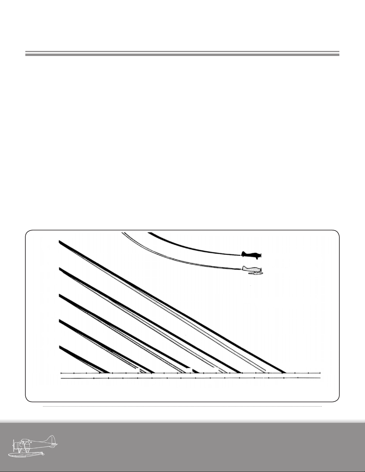
For every 2,000 feet, Landplane will glide approximately 3-1/2 statute miles and Seaplane will glide 3-1/4 statute miles in still air.
2 4 6 8 10 12 14 16 18
2 4 6 8 10 12 14 16
FOR MAXIMUM GLIDE DISTANCE
KEEP FLAPS UP
Fi gur e 5 -1 - gl idi ng dista nCes
LANDPLANE
SEAPLANE
STATUTE MILES
NAUTICAL MILES
95 mph
(82 knots)
92 mph
(80 knots)
military visualizations page
DHC-2 BEAVER
36
Page 43

SECTION 5 - EMERGENCY PROCEDURES
5.1 ENGINE FAILURE
(e) Ignition - OFF.
(f) Battery master switch - OFF.
5.1.1 ENGINE FAILURE DURING
TAKEOFF RUN
Remaining length of runway is sucient for stop-
ping safely.
(a) Apply brakes - control column fully back all the
time.
(b) Mixture lever - IDLE CUT-OFF.
(c) Pump aps fully DOWN.
(d) Ignition - OFF.
(e) Fuel Selector - OFF.
(f) Battery master switch - OFF.
Space ahead is insucient.
(a) Take steps as above.
(g) Fuel Selector - OFF.
(h) Warn passengers to brace feet against supports
and protect their heads by placing an arm across forehead, gripping fuselage structure with the same hand.
(j) KEEP STRAIGHT AHEAD AND CHANGE DIRECTION
ONLY ENOUGH TO MISS OBSTACLES. USE RUDDER ONLY.
CAUTION
Always maintain enough airspeed to assure
full control of aircraft to point of touchdown.
Coarse use of ailerons near the stall airspeed
precipitates wing dropping.
CAUTION
It is better to ride an aircraft with a dead engine safely to a crash landing straight ahead,
than to turn back to the eld. Attempts to
turn back have, in many cases, ended with
an uncontrolled roll or spin into the ground.
(b) Turn the aircraft by momentarily applying dierential braking in the desired direction, rudder pedals in
neutral, then apply dierential braking in the reverse direction to counteract ground looping tendency.
5.1.2 ENGINE FAILURE AFTER TAKEOFF
(a) Lower nose immediately, to maintain airspeed at
65 mph.
(b) Mixture lever - IDLE CUT-OFF.
(c) Propeller lever to DECREASE RPM position.
(d) Fuel and oil emergency shut-o - pull sharply
CLOSED.
5.1.3 ENGINE FAILURE ABOVE 800 FT. AFTER
TAKEOFF
(a) Depress nose to gliding attitude.
(b) Flaps to CRUISE.
(c) Propeller lever to full DECREASE RPM position.
(d) Maintain airspeed of 95 mph IAS (glide gradient is
11% rate of descent 890 ft. per minute.)
(e) Decide whether to crash land straight ahead or
complete the circuit and attempt to land on the aireld.
(f) Proceed as described in DEAD ENGINE LANDING.
military visualizations page
DHC-2 BEAVER
37
Page 44

SECTION 5 - EMERGENCY PROCEDURES
5.1.4 ENGINE FAILURE DURING FLIGHT
If sucient altitude is available:
Attempt to re-start the engine as follows:
(a) Lower nose and maintain airspeed at 95 mph.
(b) Fuel selector at fullest tank.
(c) Check fuel pressure within normal range.
(d) Check that some oil pressure is indicated. Do not
attempt to re-start if there is no oil pressure.
(e) Throttle - 1/3 open.
(f) Check ignition switches - BOTH.
(g) If no fuel pressure is indicated.
(h) Booster pump - ON (if installed) or:
Use wobble pump to build up fuel pressure and prime
for a maximum of 4 strokes. If still no fuel pressure do not
attempt a re-start.
5.2 DEAD ENGINE LANDING
(a) Maintain air speed of 95 mph IAS, aps at CRUISE
for maximum glide distance.
(b) Propeller lever - HIGH PITCH.
(c) Mixture lever - IDLE CUT-OFF.
(d) Throttle lever - CLOSED.
Close to ground:
(e) Ignition switch - OFF.
(f) Order occupants to brace themselves.
(g) Flaps to LANDING and maintain nal approach
speed of 65 - 68 mph.
(h) Touch down slightly tail rst, as nearly into the
wind as circumstances permit.
(j) Leave aircraft immediately when it has stopped
moving.
If re-start fails:
(a) Ignition switch - OFF.
(b) Propeller lever full DECREASE RPM position.
(c) Fuel selector - OFF.
(d) Maintain air speed of 95 mph IAS with aps at
CRUISE for maximum glide distance.
(e) Throttle lever - CLOSED.
(f) Make a dead engine landing.
5.3 PROPELLER FAILURE
Failure of the constant speed unit will result in the
propeller going into coarse pitch and remaining there.
No attempt should be made to clear the failure by increasing engine power as this will overload the engine
and lead to possible engine failure.
It is recommended that a landing be made at the
nearest aireld, using limited power with propeller lever
in HIGH PITCH position, to have the trouble rectied.
5.3.1 PROPELLER FAILURE DURING TAKEOFF
RUN
Abandon take-o as follows:
military visualizations page
DHC-2 BEAVER
38
Page 45

SECTION 5 - EMERGENCY PROCEDURES
(a) Close the throttle.
(b) Mixture lever - IDLE CUT-OFF.
(c) Pump aps fully down.
(d) Apply brakes.
(e) When speed is low and remaining space insucient, turn the aircraft by dierential braking.
(f) Fuel selector - OFF.
(g) Ignition switch - OFF.
(h) Master switch - OFF.
5.3.2 PROPELLER FAILURE AFTER TAKEOFF
1. (a) If RPM too high manipulate propeller lever in
attempt to bring propeller within limits.
(b) If no response, throttle back to keep the RPM
below 2350 rpm. Leave aps at TAKEOFF and maintain
airspeed at 65 mph minimum.
(c) If unsuccessful, return to eld maintaining nose
up attitude and regulate the rate of descent by gentle
throttle lever manipulation. Resume normal attitude on
the approach to land and make a power o landing.
2. (a) If RPM too low (propeller in full coarse pitch.)
(b) Increase air speed without losing altitude.
(c) If possible reduce throttle to 30 In.Hg.
5.3.3 PROPELLER FAILURE DURING FLIGHT
Overspeeding Propeller (Sticking in low pitch)
(a) Reduce throttle setting and pull the aircraft into a
climbing altitude to decrease engine speed and increase
load on the propeller.
(b) Manipulate propeller lever in attempt to bring
propeller within operating limitations.
(c) Maintain constant check on oil pressure.
Oil supply breakdown
(a) Check oil pressure; if none is indicated, pull propeller lever to HIGH PITCH.
(b) Keep RPM to a minimum and make an emergency
landing with limited power on.
(c) If oil pressure is indicated after selecting HIGH
PITCH it can be assumed that the propeller oil line has
fractured so proceed as in 5.3.2.
5.4 DITCHING
Any high-wing monoplane should be ditched only
as a last resort because even in the exceptional case
where the pilot succeeds in ditching his airplane under
favourable conditions, there is the almost certain possibility that the aircraft will submerge to the cabin roof in
a very short time.
If, however, the aircraft has to be ditched, proceed
as follows:
(d) Raise aps to CLIMB in stages, maintaining
maximum air speed and climb at the slowest rate to gain
sucient altitude to complete a safe circuit and landing.
military visualizations page
DHC-2 BEAVER
(a) Keep approach speed sucient for control down
to the impact with the water.
(b) Instruct other occupants of the aircraft.
39
Page 46

SECTION 5 - EMERGENCY PROCEDURES
(c) Make approach into the wind, at right angles to
the swell.
(a) Unfasten collar and tie.
(d) Unlock cabin and cockpit doors.
(e) Ditch on the falling side of a wave crest or swell
top.
(f) Touch down tail rst to prevent the nose from
striking a wave crest or swell top which might cause the
aircraft to nose in, or dive under.
Other occupants of the aircraft should be instructed as
follows:
(b) Hold on to life preserver cushions.
(c) Be prepared for a double impact when rst the tail,
and then the engine strike water.
(d) Not to move until the aircraft has come to rest.
(e) Help each other through the doors as quickly as
possible.
military visualizations page
DHC-2 BEAVER
40
Page 47
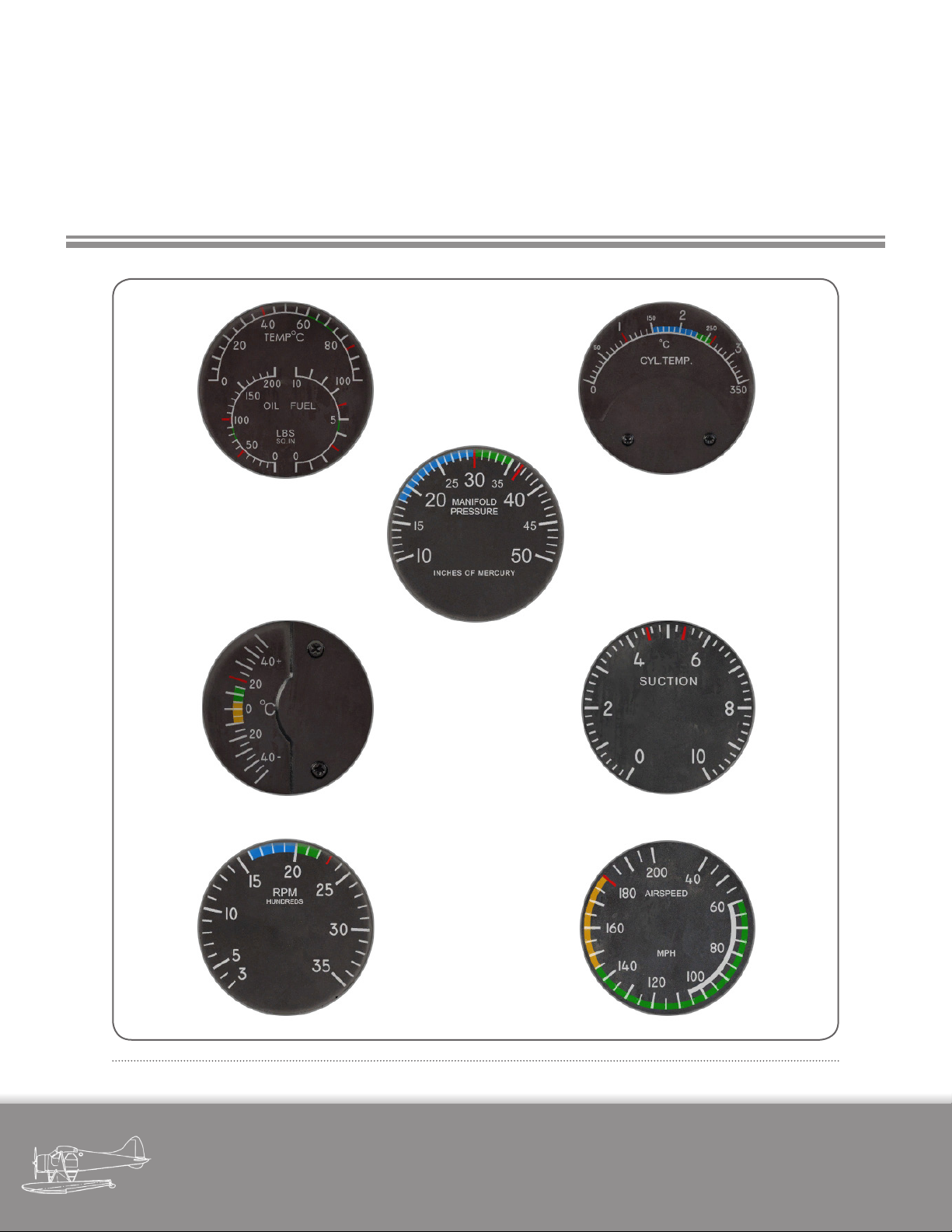
6. OPERATING LIMITS,
PERFORMANCE DATA AND
FLIGHT CHARACTERISTICS
FUEL AND OIL PRESS, OIL TEMP. CYLINDER HEAD TEMP.
CARB. MIXTURE TEMP. SUCTION
TACHOMETER AIRSPEED
Fi gur e 6 -1 - in str ume nt li mi t ma rki ngs
MANIFOLD PRESS.
TAKEOFF POWER TIME LIMIT:
1 MIN. AT 2300 RPM
36.5 IN. HG.
CAUTION
AT AMBIENT TEMPERATURES BELOW
STANDARD ALTITUDE TEMPERATURE
15°C 59°F AT S. L. WITH CARBURE
TOR AIR AT COLD, OVERBOOSTING
AND DETONATION ARE POSSIBLE AT
MAP SETTINGS BELOW THE NORMAL
MAXIMUM PERMISSIBLE. THEREFORE,
TAKEOFF MAP MUST BE REDUCED
BY 2% PER 11°C 20°F BELOW STAND
ARD, IF ENGINE LIFE IS TO BE PRE
SERVED.
MAX. CONTINUOUS POWER
2200 RPM 33.5 IN. HG.
FULL RICH
military visualizations page
DHC-2 BEAVER
41
Page 48

SECTION 6 - OPERATING LIMITS, PERF. DATA AND FLIGHT CHARACTERISTICS
6.1 GENERAL REMARKS
The aircraft must be operated according to the fol-
lowing limitations and instructions.
Instrument readings, illustrating the operating
limitations, are shown on Figure 6-1. The instrument
markings shown should be given close attention since
they contain operational limits information which is not
necessarily repeated in the following text.
7.1.1 The aircraft has been classied in the normal cat-
egory of BCAR Airworthiness standards in accordance
with the Type Approval.
ALL AEROBATIC MANOEUVRES, INCLUDING SPINS ARE
PROHIBITED.
Stalls are permitted for demonstration purposes only.
6.2 ENGINE LIMITATIONS
Refer to: Instrument Markings (Figure 6-1).
6.5 AIRSPEED LIMITS
For AIRSPEED LIMITATIONS as marked on Air-
speed Indicator refer to Figure 6-1.
6.5.1 MAXIMUM PERMISSIBLE DIVING SPEED
Landplane )
Skiplane ) 180 mph IAS
Seaplane )
The maximum permissible speed is the never-exceed speed of ight. A higher speed may result in structural failure, utter or loss of control.
6.5.2 NORMAL OPERATING LIMIT SPEED
Landplane )
Skiplane ) 145 mph IAS
Seaplane )
CAUTION
If engine overspeeding occurs, land at nearest aireld and have engine and propeller
inspected before further ight. If engine has
exceeded 2,750 rpm for more than 30 seconds, an engine change is indicated.
6.3 PROPELLER LIMITATIONS
Provided that the engine is operated within en-
gine limitations, the propeller will be within its safe limits. Excessive run-up on the ground is to be avoided.
6.4 RESIDUAL FUEL QUANTITIES
Fuel remaining in tanks when the fuel contents
gauge indicates zero, cannot be safely used in ight.
Normal cruising ight operations should be con-
ned to speeds below this value.
The range of speed between normal operating
limit speed and the maximum permissible diving speed
should be intentionally entered only with due regard to
the prevailing ight and atmospheric conditions, in particular turbulence.
6.5.3 MANOEUVRING SPEED
125 mph IAS. Manoeuvres which involve an approach to stall conditions, or full application of rudder
or aileron control, should be conned to speeds below
this value.
military visualizations page
DHC-2 BEAVER
42
Page 49
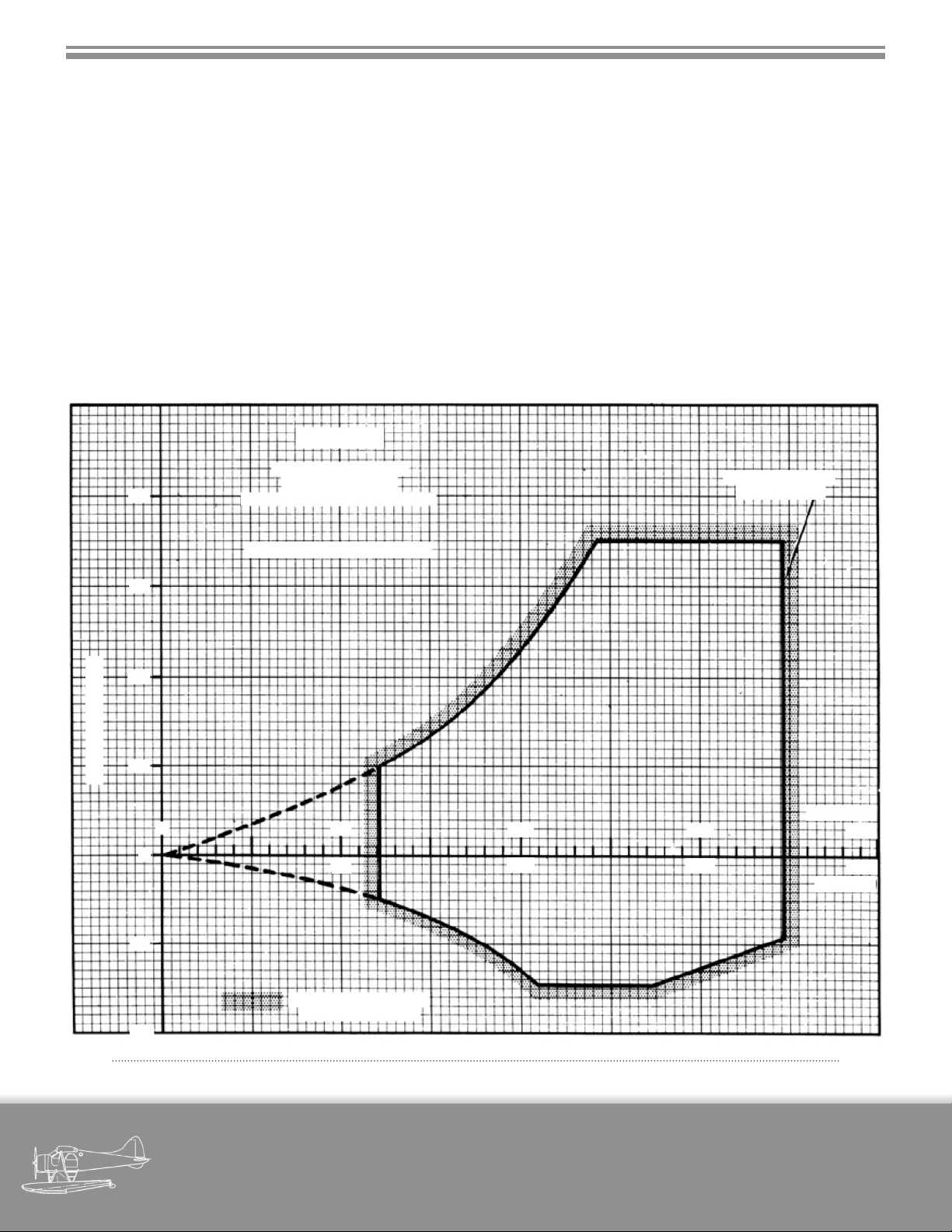
SECTION 6 - OPERATING LIMITS, PERF. DATA AND FLIGHT CHARACTERISTICS
When ying in very rough air, or if it is necessary to
6.5.4 MAXIMUM SPEED FOR
LOWERING FLAPS
105 mph IAS.
6.6 ACCELERATION LIMITS
Limit load factors are the maximum values which
the airframe may be safely subjected to in ight.
BEAVER
perform forcible manoeuvres including full application
of aileron and rudder, the airspeed should not be permitted to exceed 145 mph IAS.
6.6.1 LOAD FACTORS
In tight turns, ight load factors may reach the
limit loads, and may also increase the danger of an unintentional stall.
g -LOAD FACTOR
+4
+3
+2
+1
FLIGHT ENVELOPE
(V-g) DIAGRAM
LANDPLANE & SEAPLANE
GROSS WEIGHT 5100 LB.
0
0
58
50
115
100
173
150
MAX 200 MPH
(173 KNOTS)
IAS - MPH
230
200
(KNOTS)
-1
PROHIBITED AREA
OF OPERATION
-2
Fi gur e 6 -2 - op erat ing Fl igH t s t ren gtH dia gra m
military visualizations page
DHC-2 BEAVER
43
Page 50
SECTION 6 - OPERATING LIMITS, PERF. DATA AND FLIGHT CHARACTERISTICS
The variation of aps-up stalling speed and load
factors with angle of bank are given below:
6.8 MINIMUM FLIGHT CREW
Angle of Bank
mph IAS
0
50
60
65
70
6.7 WEIGHT LIMITATIONS
The Design Gross Weight of the aircraft is 5,100 lb.
At this weight it complies with the general performance
and strength criteria.
60
85
105
115
130
Load FactorStalling Speed
1.0
1.5
2.0
2.5
3.0
One Pilot.
6.9 MISCELLANEOUS
Smoking is authorized for cockpit and cabin.
military visualizations page
DHC-2 BEAVER
44
Page 51

SECTION 6 - OPERATING LIMITS, PERF. DATA AND FLIGHT CHARACTERISTICS
6.10 PERFORMANCE AT MAXIMUM
GROSS WEIGHT
STANDARD CONDITIONS
6.10.1 GENERAL
Max. True Level Speed
Sea Level mph (kmh)
5,000 ft. mph (kmh)
True Cruising Speed (300 BHP)
Sea Level mph (kmh)
5,000 ft. mph (kmh)
Economic True Cruising Speed (240 BHP)
Sea Level mph (kmh)
Landplane
(5,100 lb)
156 (251)
163 (262)
136 (219)
143 (230)
125 (201)
Skiplane
(5,100 lb)
Seaplane
(5,090 lb)
144 (232)
151 (243)
123 (198)
127 (204)
110 (177)
5,000 ft. mph (kmh)
Stalling Speed (I.A.S.)
Flaps Up mph (kmh)
Flaps “Landing” mph (kmh)
Take-o distance to clear 50 ft. obstacle
(Flaps “Take-o”, still air
ICAO technique) ft. (m)
military visualizations page
DHC-2 BEAVER
130 (209)
60 (96)
45 (72)
1,250 (381)
114 (183)
60 (96)
45 (72)
1,610 (491)
45
Page 52

SECTION 6 - OPERATING LIMITS, PERF. DATA AND FLIGHT CHARACTERISTICS
Landing distance over 50 ft. obstacle
(Flaps “Landing”, still air
ICAO technique) ft. (m)
Initial Rate of Climb (Take-o Power)
Flaps up fpm (m/sec)
Flaps “Take-o” fpm (m/sec)
Service Ceiling ft. (m)
Rate of Climb at Max. Cont. Power
Sea Level fpm (m/sec)
5,000 ft. fpm (m/sec)
10,000 ft. fpm (m/sec)
Landplane
(5,100 lb)
1,250 (381)
1,020 (5.2)
730 (3.7)
18,000 (5490)
840 (4.3)
795 (4.0)
530 (2.7)
Skiplane
(5,100 lb)
Seaplane
(5,090 lb)
1,510 (460)
920 (m/sec)
650 (3.3)
15,750 (4800)
740 (3.8)
685 (3.5)
410 (2.1)
Cruising Range at 5,000 ft. (240 BHP)
With normal fuel capacity mi (km)
(79 Imp. Gal.) (95 U.S. Gal.)
Cruising Endurance at 5,000 ft. (240 BHP)
With normal fuel capacity
(79 Imp. Gal.) (95 U.S. Gal.)
Note: Range and endurance results make allowance for:
i) 10 min. warm up and take-o
ii) Climb to 5,000 ft.
iii) Fuel for 45 min. ight at cruise power (240 BHP)
455 (732)
3.54 hrs.
405 (652)
3.52 hrs.
military visualizations page
DHC-2 BEAVER
46
Page 53

SECTION 6 - OPERATING LIMITS, PERF. DATA AND FLIGHT CHARACTERISTICS
6.10.2 MAX. INDICATED SPEEDS
Flaps mph (kmh)
Diving 5,100 A.U.W. mph (kmh)
Structural
Cruising mph (kmh)
6.11 FLIGHT CHARACTERISTICS
6.11.1 GENERAL
Stability is good about all axes. The aircraft is easy
to y and is docile down to the stall. Controls are normally eective throughout the airspeed range. The aircraft
can be trimmed to y hands-o from climb to maximum
speeds.
6.11.2 TAKEOFF
105 (169)
180 (290)
145 (233)
6.11.4 SPINS
Intentional spinning of the aircraft is prohibited.
6.11.5 STALL
The stall is gentle at all normal conditions of load
and ap and may be anticipated by a slight vibration,
which increases as ap is lowered. The aircraft will pitch
if no yaw is present. If yaw is permitted, the aircraft has a
tendency to roll. Prompt corrective action must be initiated to prevent the roll from developing.
105 (169)
180 (290)
145 (233)
When trimmed appropriately, stick forces are
moderate. The aircraft will y itself o at airspeeds of 50
to 60 mph IAS in a tail low attitude.
6.11.3 SLOW FLYING
It is possible to retain full control of the aircraft at: -
75 mph IAS with aps at CRUISE
65 mph IAS with aps at LANDING
military visualizations page
DHC-2 BEAVER
47
Page 54

7. SPECIAL INSTALLATIONS
7.1 Combination Wheel-Ski
Installation
The de Havilland combination wheel-ski installation permits normal operation on wheels or skis at the
discretion of the pilot. It is possible to taxi immediately
from snow covered ground onto cleared runways or dispersal areas and vice versa since the skis can be raised or
lowered while the aircraft is being taxied.
7.1.1 GENERAL
The skis are raised or lowered in relation to the
wheels by means of a hydraulic control unit located on
the cockpit oor to the right of the pilot’s seat.
The skis are raised by selecting UP on the selector lever then operating the hydraulic handpump which
supplies hydraulic pressure to extend an actuator and
cause the ski linkage to swivel on the axle attachments.
The hydraulic pressure works in opposition to a compressed air charge, in the upper portion of the actuator
housing, which is used as a pneumatic spring to cushion
the landing.
To lower the skis, select DOWN on the ski selector
lever which will release the hydraulic pressure and allow
the pneumatic pressure in the upper portion of the actuator housing, to return the skis to the DOWN position
as shown on the indicator in the selector unit.
7.1.2 OPERATION
To lower skis select DOWN on the ski selector lever.
After a few seconds the indicator will show that the skis
are in the down position.
To raise the skis select UP on the ski selector lever. Operate the hand pump until the skis are fully UP
as shown by the needle on the indicator. Approximately
100 strokes of the handpump are required to raise the
skis fully. (No worries - in the interest of sanity, the hand-
pump we’ve installed in the MilViz DHC-2 only requires one
click to activate!)
NOTE
The skis trim safely in ight at any degree of
retraction. Therefore, the pumping may be
completed at the pilot’s convenience.
7.1.3 AFTER TAKEOFF
The ski position has no signicant eect on air-
speed, CG position or ight characteristics. The skis,
therefore, may be left in either UP or DOWN position as
dictated by conditions at the arrival landing eld.
7.1.4 BEFORE LANDING
Prior to the approach to land the pilot should de-
cide whether to raise or lower the skis, depending on
forecast conditions of the landing eld. Select skis as
desired and when the action is complete check the ski
position visually and on the indicator.
7.1.5 LANDING
Make a normal approach at the speeds recom-
mended in Section 4. 13.
A tail-down or three point landing attitude should
be attained on the nal stage of the approach to reduce
the landing run, and, when skis are extended, to ensure
that lumps of snow or ice do not foul the ski tips on
touchdown.
military visualizations page
DHC-2 BEAVER
48
Page 55

SECTION 7 - SPECIAL INSTALLATIONS
7.1.6 CROSSWIND LANDINGS
When landing with the skis extended the crosswind component should be carefully considered against
the pilot’s experience and the condition of the landing
area at that time. Landings with crosswind components
equal to 12 mph at 90° are not recommended.
7.1.7 AFTER LANDING
As soon as possible, after touchdown, ease the
control column fully back to ensure directional control
via the rudder pedals and tail ski and proceed as in Section 4. 16.
7.2 Amphibious Floats
The de Havilland amphibious oats installation enables routine ights to be made, from aireld to aireld,
water to water, aireld to water and water to aireld conveniently and simply without delays in re-equipping the
aircraft.
7.2.1 GENERAL
The oats installation replaces the complete landplane landing gear system. The oats are equipped with
retractable water rudders, main and nose wheels. The retraction and extension of the wheels is accomplished by
means of hydraulic pressure emanating from a hydraulic
control unit, located on the oor to the right of the pilot’s
seat. The main wheel braking system is also operated hydraulically through actuation of the rudder toe pedals.
the water rudders are actuated through a cable and pulley system for retraction, extension and steering.
7.2.2 TAXIING
Seaplane
Ensure that the wheels are retracted (UP). Extend
the water rudders and proceed to take-o point. Allow
the seaplane to weathercock into the wind and complete
engine checks, if not already done. Retract water rudders
and take-o into the wind. The water rudders may be left
extended to assist in cross-wind take-os.
Landplane
In addition to the checks in Section 4. 7, make sure
the wheels are selected DOWN. Before commencing
taxiing, check that the water rudders retraction handle
is in the retracted position. Test the brakes as soon as the
aircraft starts moving.
NOTE
Although the aircraft is in a tricycle undercarriage attitude giving better taxiing visibility more care should be taken to avoid
rough or uneven ground in order to avoid
damage to the oats. Furthermore, when
manoeuvring, the pilot must keep in mind
the additional area required for the length
of the oats.
7.2.3 TAKEOFF
Landplane
In addition to the checks in Section 4. 9 check the
following:
(a) Wheels DOWN.
(b) Water rudders - Retracted.
(c) Brakes - OFF.
military visualizations page
DHC-2 BEAVER
49
Page 56

SECTION 7 - SPECIAL INSTALLATIONS
(d) Open throttle slowly to take-o power and note that
the aircraft accelerates more rapidly, because of the tricycle attitude. Maintain directional control by coarse use
of the rudder initially.
(e) Allow the speed to increase to 60 or 65 mph before
applying a slight backward pressure to the control column to assist the aircraft in unsticking.
(f) As the nose wheels lift clear of the ground a slight forward pressure should be applied to the control column
to maintain the take-o attitude.
Seaplane
Complete the normal checks in Section 4. 9 with
the addition of the following:
(a) Wheels UP.
(b) Water rudders - Retracted.
If the landing is to be made:
(a) On water, the wheels and the water rudders much be
retracted (UP).
(b) On land, the wheels must be selected DOWN and
locked and the water rudders retracted.
The water rudders retraction is simply a matter of
checking that the retraction handle is in the retracted
position where it should of been before take-o and during the ight.
The wheels, however, require that :
(a) The selector lever on the amphibious oats hydraulic
control unit be selected as desired.
(b) The handpump is operated until the desired position
is shown on the hydraulic control indicator.
(c) Open throttle smoothly and maintain direction with
the airplane rudder. Allow the seaplane to y itself o at
approximately 65 mph.
7.2.4 CLIMBING, CRUISING AND
DESCENDING
In ight whether climbing, cruising or descending, the eects of the amphibious oats are the same
as those encountered with normal oats. However, to
improve the ight characteristics, the wheels should be
retracted during ight. The water rudders should be retracted during take-o and remain retracted until after a
water landing has been completed.
7.2.5 LANDING
Before approaching to land at the termination of
the ight, the pilot must consider his intended landing
area and take action accordingly.
7.2.6 OPERATING LIMITS
The All-Up Weight of the amphibian when operating on water must not exceed 5000 lb, the reduction in
A.U.W. from the standard seaplane version is necessary
due to the decreased buoyancy of the amphibious oats.
NOTE
Handling and performance are unchanged,
except as stated below.
Handling
On wheels, if take-o is attempted at the minimum
speed of 58-60 mph IAS, the nose, once lifted will tend
to rise and must be checked. This is a normal nose wheel
airplane characteristic and is easily controlled by the elevator. If the nose is left down until 80 mph IAS, this characteristic is absent.
Performance
military visualizations page
DHC-2 BEAVER
50
Page 57

SECTION 7 - SPECIAL INSTALLATIONS
There is negligible dierence between the wheels up
and down performance.
Runway take-o - Add 50 ft to landplane gure (Chart I).
Runway landing - Add 95 ft to landplane gure (Chart II).
Rate of climb - Subtract 50 fpm from seaplane values.
Speed at maximum weak mixture power (300 BHP) Subtract 2-1/2 mph from seaplane values.
Speed at standard cruise (240 BHP) - Subtract 5 mph
from seaplane values.
military visualizations page
DHC-2 BEAVER
51
Page 58

8. OPERATING DATA CHARTS
NOTE
The take-o and landing distances on the following
charts assume ICAO technique during take-o and landing, namely, holding the aircraft down until the airspeed
builds up to 1.2 times the stalling speed before climbing
on take-o, and holding 1.3 times the stalling speed during the approach to land.
military visualizations page
DHC-2 BEAVER
52
Page 59
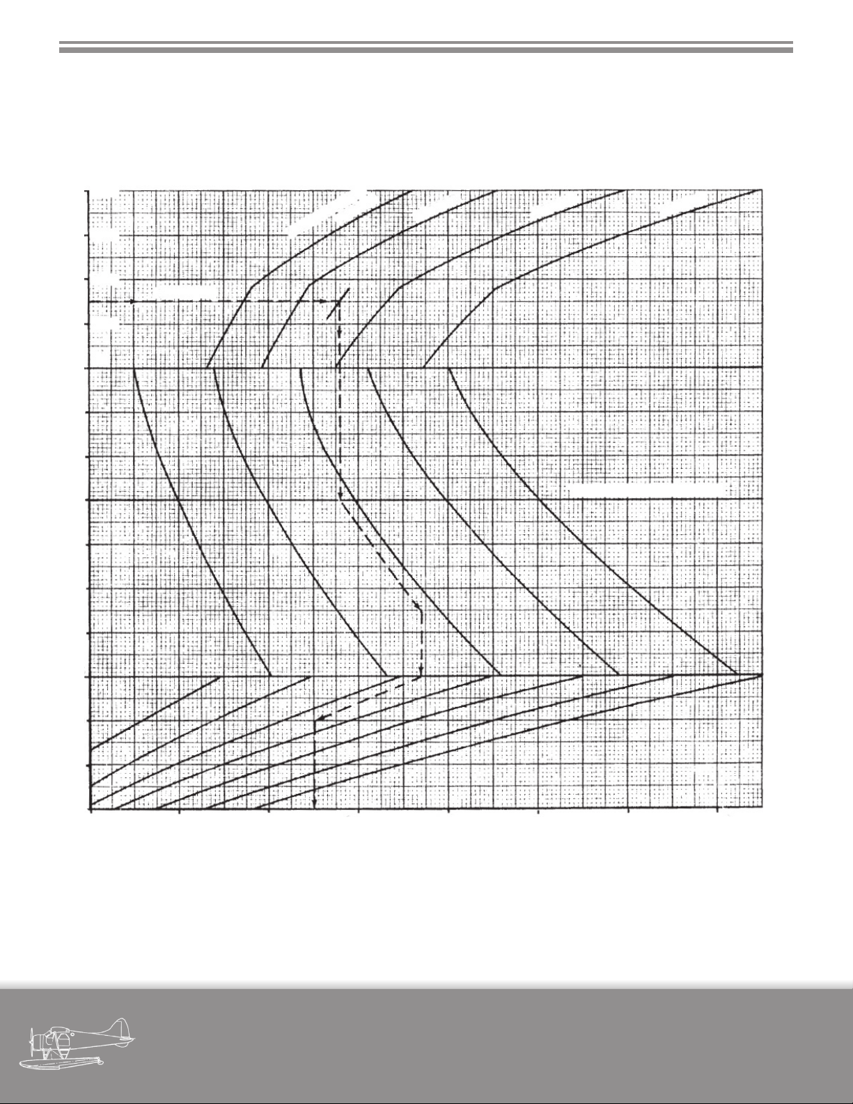
SECTION 8 - OPERATING DATA CHARTS
8.1 TAKEOFF DISTANCE LANDPLANE
REMARKS:
1. Runway: Hard Surface
2. Flaps: “Take-o”
8000
4000 LB
-15
-5
6000
4000
2000
SL
GROSS WEIGHT
EXAMPLE
3. Ground run is approximately 55% of total distance.
4. Data: Estimated (ICAO technique)
4400 LB
4820 LB
5100 LB
+5
+15
+25
+35
+45
+55
0
10
20
HEADWIND - MPH TEMPERATURE - °C PRESSURE ALTITUDE - FT
30
500 700 900 1100 1300 1500 1700 1900
TOTAL TAKE-OFF DISTANCE TO CLEAR 50 FT OBSTACLE - FT
TEMPERATURE BASE LINE
EXAMPLE:
1. Follow Pressure Altitude line (3000 ft) horizontally to
Gross Weight contour (4600 lb)
2. Drop vertical line to Temperature Base Line
3. Follow closest Temperature contour to existing
temperature line
military visualizations page
DHC-2 BEAVER
4. Drop vertical line to zero wind line
5. Follow closest Headwind contour to existing
headwind line (10 mph)
6. Drop vertical line to Distance axis and read:
Total take-o distance to clear 50 ft = 1000 ft
53
Page 60
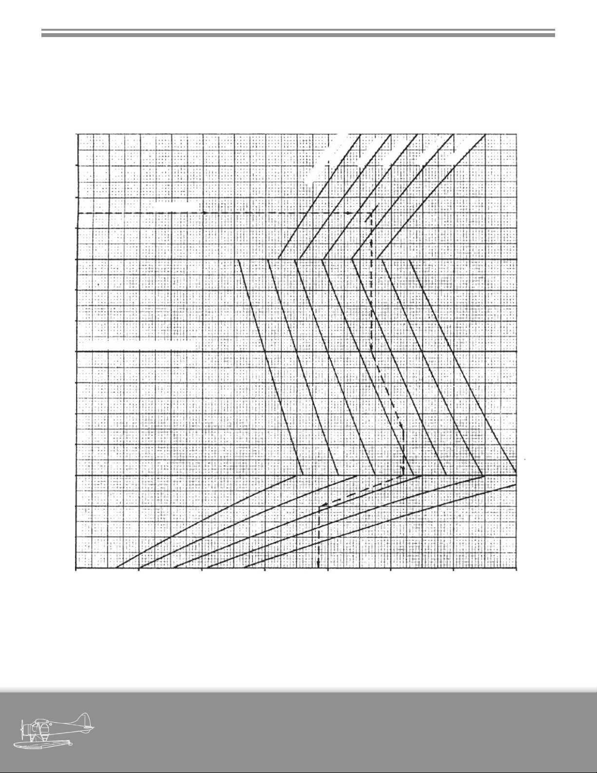
SECTION 8 - OPERATING DATA CHARTS
8.2 LANDING DISTANCE LANDPLANE
REMARKS:
1. Runway: Hard Surface
2. Flaps: “Landing”
8000
3. Ground run is approximately 50% of total distance.
4. Data: Estimated (ICAO technique)
6000
4000
2000
SL
-15
-5
+5
+15
+25
+35
EXAMPLE
TEMPERATURE BASE LINE
3600 LB
GROSS WEIGHT
4000 LB
4400 LB
4820 LB
5100 LB
+45
+55
0
10
20
HEADWIND - MPH TEMPERATURE - °C PRESSURE ALTITUDE - FT
30
300 500 700 900 1100 1300 1500 1700
TOTAL LANDING DISTANCE FROM 50 FT OBSTACLE - FT
EXAMPLE:
Follow example line using procedure given for landplane take-o and read:
Total landing distance from 50 ft obstacle = 1070 ft
military visualizations page
DHC-2 BEAVER
54
Page 61

SECTION 8 - OPERATING DATA CHARTS
8.3 SKIPLANE TAKEOFF AND LANDING DISTANCES
Snow conditions being extremely variable, the sliding coecient of friction
which has an important eect on Take-o and landing ground distances,
may vary between wide limits.
( μ = 0.02 to μ = 1.2 ).
Take-O
(1) Under doubtful snow conditions:
(a) Expect “sticky snow” ground run ( μ > 0.3 ).
(2) If the pilot is suciently familiar with the snow conditions to know
that the sliding friction is normal ( μ < 0.3 ):
(a) Add 1000 feet to the landplane gures to obtain length of ground
run.
(3) On very “slippery” snow or ice ( μ < 0.1 ):
(a) Add 100 feet to the landplane gures.
(4) In very “sticky” snow ( μ > 0.3 ):
(a) Expect a take-o ground run in excess of 2000 to 3000 feet.
Landing
Since weather conditions may change rapidly, there is a possibility that
snow which was “sticky” on take-o may prove very “slippery” on landing.
(1) Under doubtful conditions:
(a) Allow for a ground run in excess of 2000 feet ( μ < 0.1 ).
(2) If conditions are known to be favourable:
(a) Add 400 feet to ground run values for the landplane ( μ > 0.1 ).
military visualizations page
DHC-2 BEAVER
55
Page 62
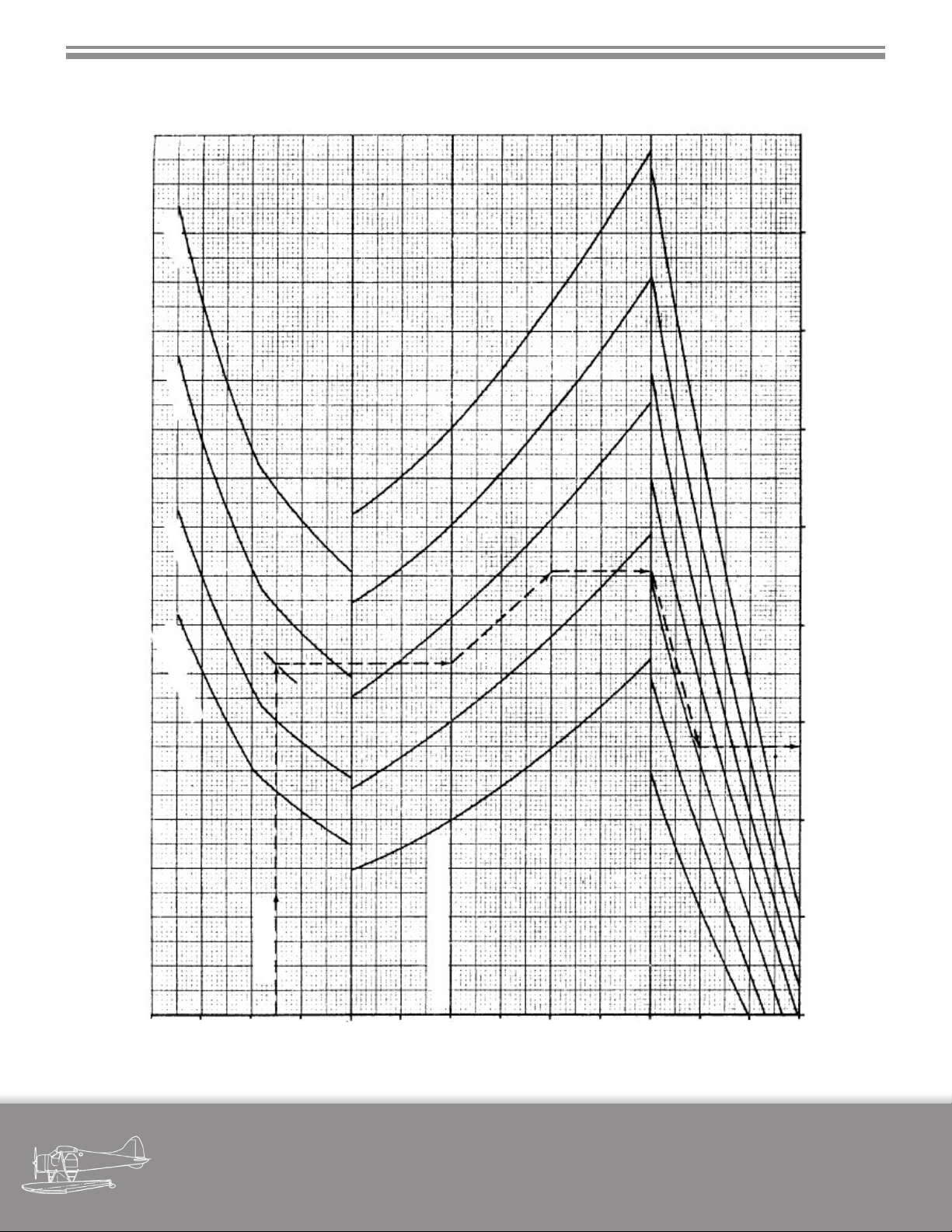
SECTION 9 - OPERATING DATA CHARTS
8.4 TAKEOFF DISTANCE SEAPLANE
5090 LB
4820 LB
4400 LB
4000 LB
2300
GROSS WEIGHT
TOTAL TAKE-OFF DISTANCE TO CLEAR 50 FT OBSTACLE - FT
1100 2100700 900 19001300 1500 1700
EXAMPLE
8000
6000
4000
2000
SL
-5
+5
TEMPERATURE BASE LINE
+15
+25
+35
+45
+55
0
10
20
30
HEADWIND - MPH TEMPERATURE - °C PRESSURE ALTITUDE - FT
EXAMPLE:
Follow example line using procedure given for landplane take-o and read:
military visualizations page
Total take-o distance to clear 50 ft obstacle = 1250 ft
DHC-2 BEAVER
56
Page 63
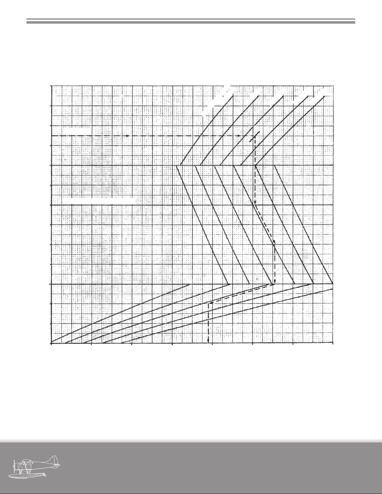
SECTION 9 - OPERATING DATA CHARTS
8.5 LANDING DISTANCE SEAPLANE
REMARKS:
1. Water: Calm
2. Flaps: “Landing”
8000
3. Water run is approximately 58% of total distance.
4. Data: Estimated (ICAO technique)
6000
4000
2000
SL
-5
+5
+15
+25
+35
+45
+55
3600 LB
GROSS WEIGHT
EXAMPLE
TEMPERATURE BASE LINE
0
4000 LB
4400 LB
4820 LB
5090 LB
10
20
HEADWIND - MPH TEMPERATURE - °C PRESSURE ALTITUDE - FT
30
500 700 900 1100 1300 1500 1700 1900
TOTAL LANDING DISTANCE FROM 50 FT OBSTACLE - FT
EXAMPLE:
Follow example line using procedure given for landplane take-o and read:
Total landing distance from 50 ft obstacle = 1280 ft
military visualizations page
DHC-2 BEAVER
57
Page 64
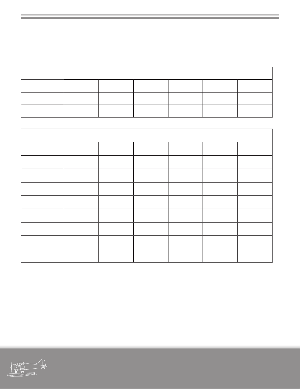
SECTION 9 - OPERATING DATA CHARTS
8.6 CRUISE POWER CHART
ENGINE: Pratt & Whitney WASP JUNIOR R985 ALL MODELS
FUEL CONSUMPTION
Imp. Gal/hr 14.1 15.2 16.5 18.4 20.8 23.1
U.S. Gal/hr 16.9 18.2 19.8 22 25 28.5
B.H.P. 200 220 240 260 280 300
Altitude R.P.M. and MAINFOLD PRESSURE
S.L. 1600 - 26.7 1600 - 28.5 1650 - 29.5 1750 - 29.7 1900 - 29.2 2000 - 29.7
1000 1600 - 26.5 1600 - 28.5 1650 - 29.2 1750 - 29.7 1900 - 29.2 2000 - 29.5
2000 1600 - 26 1600 - 27.7 1650 - 29 1750 - 29.2 1900 - 28.7 2000 - 29.2
3000 1600 - 25.7 1600 - 27.5 1650 - 28.7 1750 - 29 1900 - 28.5 2000 - 29
4000 1600 - 25.5 1600 - 27 1650 - 28.2 1750 - 28.7 1900 - 28.2 2000 - 28.5
5000 1600 - 25.2 1600 - 26.7 1650 - 28 1750 - 28.2 1900 - 28 2000 - 28.2
6000 1600 - 25.2 1600 - 26.5 1700 - 27.5 1750 - 27.7 1900 - 27.7 2000 - 28
7000 1600 - 25 1600 - 26.2 1700 - 27 1750 - 27.2 1900 - 27.5 2000 - 27.7
8000 1600 - 24.7 1600 - 26 1700 - 26.5 1800 - 26.7 1900 - 27.2 2000 - 27.5
Note: Above R.P.M. and Manifold Pressure chart provided for power setting reference only,
simulator usage may not match above stated Fuel Consumption.
military visualizations page
DHC-2 BEAVER
58
Page 65

CREDITS
Development
Colin Pearson - Creative Director
Tom Falley - Flight Dynamics
Chuck Jodry - Lead Code
Tom Aguilo - Systems Code
Mike Maarse - Sound Engineer
Brandon Filer - AMS Code
Collin Biedenkapp - AMS Updater
Gunnar van der Meeren - Livery Artist
Jim Stewart - Manual
Ville Keranen - Videographer
Yoyo - Imagery
Peter Krause (SoulMade Simulations) - Initial Model & Textures
3DR - Model & Textures
Testers
Mike Cameron, Vassilios (Dimus) Dimoulas, Ryan Butterworth, Robbie Nauts
WX Advantage Radar included courtesy of MilViz & REX Simulations
XMLTools included courtesy of Tom Aguilo
military visualizations page
DHC-2 BEAVER
59
 Loading...