

Page 1

Milesight IoT
Smart Button
Featuring LoRaWAN
®
WS101
User Guide
Page 2
2
Safety Precautions
Date
Doc Version
Description
July 12, 2021
V 1.0
Initial version
Milesight will not shoulder responsibility for any loss or damage resulting from not following the
instructions of this operating guide.
The device must not be modified in any way.
Do not place the device close to objects with naked flames.
Do not place the device where the temperature is below/above the operating range.
When installing the battery, please install it accurately, and do not install the reverse or
wrong model.
Remove the battery if the device will not be used for a period of time. Otherwise, the battery
will leak and damage the device.
The device must never be subjected to shocks or impacts.
Declaration of Conformity
WS101 is in conformity with the essential requirements and other relevant provisions of the CE,
FCC, and RoHS.
Copyright © 2011-2021 Milesight. All rights reserved.
All information in this guide is protected by copyright law. Whereby, no organization or individual
shall copy or reproduce the whole or part of this user guide by any means without written
authorization from Xiamen Milesight IoT Co., Ltd.
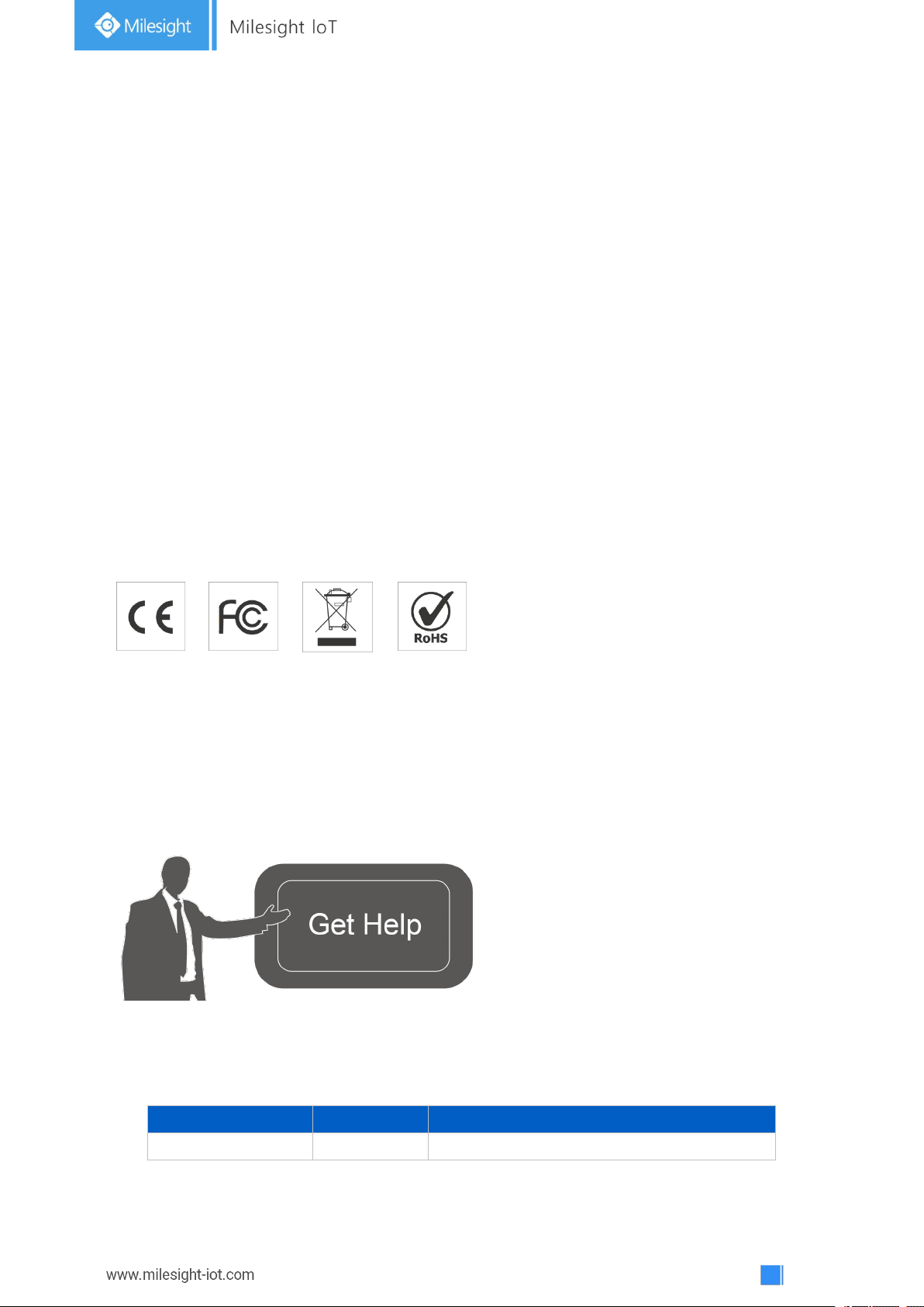
For assistance, please contact
Milesight technical support:
Email: [email protected]
Tel: 86-592-5085280
Fax: 86-592-5023065
Address: 4/F, No.63-2 Wanghai Road,
2ndSoftware Park, Xiamen, China
Revision History
Page 3
3
Contents
1. Product Introduction
1.1 Overview
1.2 Features
2. Hardware Introduction
2.1 Packing List
2.2 Hardware Overview
2.3 Dimensions (mm)
2.4 LED Patterns
3. Operation Guide
3.1 Button Mode
3.2 NFC Configuration
3.3 LoRaWAN Settings
3.4 General Settings
3.5 Maintenance
3.5.1 Upgrade
3.5.2 Backup
3.5.3 Reset to Factory Default
4. Installation
5. Device Payload
5.1 Basic Information
5.2 Button Message
5.3 Downlink Commands
................................................................................................................................................
.................................................................................................................................
...........................................................................................................................................
............................................................................................................................................
......................................................................................................................................
....................................................................................................................................
.........................................................................................................................................
....................................................................................................................................
..................................................................................................................................
...............................................................................................................................
.................................................................................................................................
........................................................................................................................................
..............................................................................................................................
.........................................................................................................................
...........................................................................................................................
..........................................................................................................................
..........................................................................................................................
..............................................................................................................................
...................................................................................................
..........................................................................................................................
............................................................................................................................
...................................................................................................................
4
4
4
4
4
5
5
5
6
6
6
7
9
10
10
10
11
12
12
12
13
14
Page 4
4
1. Product Introduction
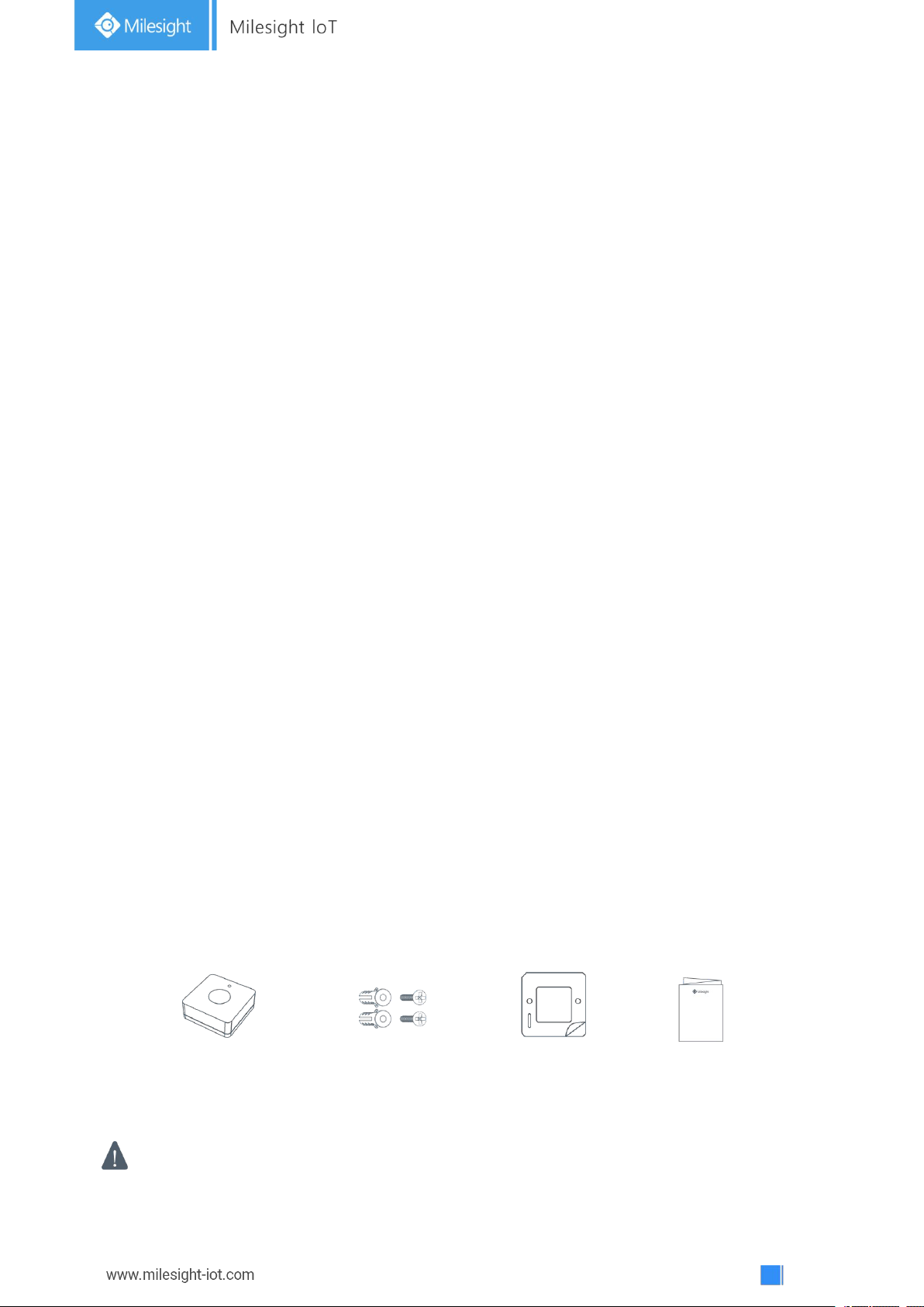
1 ×
WS101 Sensor
2 ×
Wall Mounting Kits
1 ×
3M Tape
1 ×
Quick Guide
If any of the above items is missing or damaged, please contact your sales representative.
1.1 Overview
WS101 is a LoRaWAN®based smart button for wireless controls, triggers and alarms. WS101
supports multiple press actions, all of which can be defined by the user to control devices or
trigger scenes. Besides, Milesight also provides a red button version that is primarily used for
emergency situation. Compact and battery-powered, WS101 is easy to install and carry
everywhere. WS101 can be widely used in smart homes, smart offices, hotels, schools, etc.
Sensor data are transmitted in real-time using the standard LoRaWAN®protocol. LoRaWAN
enables encrypted radio transmissions over long distances while consuming very little power.
The user can get alarm through Milesight IoT Cloud or through the user's own
Application Server.
1.2 Features
Up to 15 km communication range
Easy configuration via NFC
Standard LoRaWAN®support
Milesight IoT Cloud compliant
Support multiple press actions to control devices, trigger a scene or send emergency
alarms
Compact design, easy to install or carry
Built-in LED indicator and buzzer for press actions, network status, and low battery
indication
®
2. Hardware Introduction
2.1 Packing List
Page 5
5
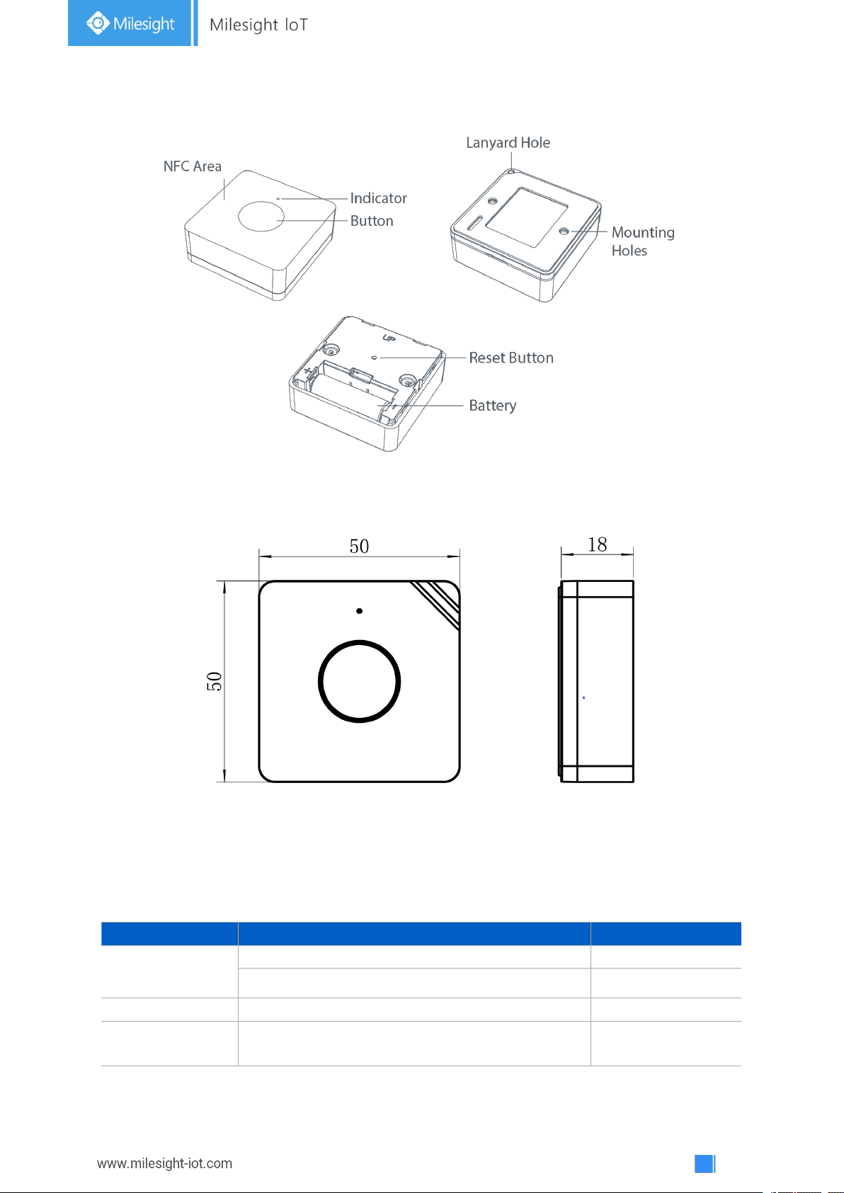
2.2 Hardware Overview
Function
Action
LED Indicator
Network Status
Send join network requests
Red, blinks once
Joined the network successfully
Green, blinks twice
Reboot
Press and hold the reset button for more than 3s
Slowly blinks
Reset to Factory
Default
Press and hold the reset button for more than 10s
Quickly blinks
2.3 Dimensions (mm)
2.4 LED Patterns
WS101 equips with a LED indicator to indicate the network status and reset button features.
Besides, when button is pressed, the indicator will light up at the same time. Red indicator
means network is unregistered, while green indicator means device has registered on network.
Page 6
6
3. Operation Guide
Mode
Action
Mode 1
Short press the button (≤3 seconds).
Mode 2
Long press the button (>3 seconds).
Mode 3
Double press the button.
3.1 Button Mode
WS101 provides 3 kinds of pressing actions allowing users to define different alarms. Please refer to
chapter 5.1 for detailed message of every action.
3.2 NFC Configuration
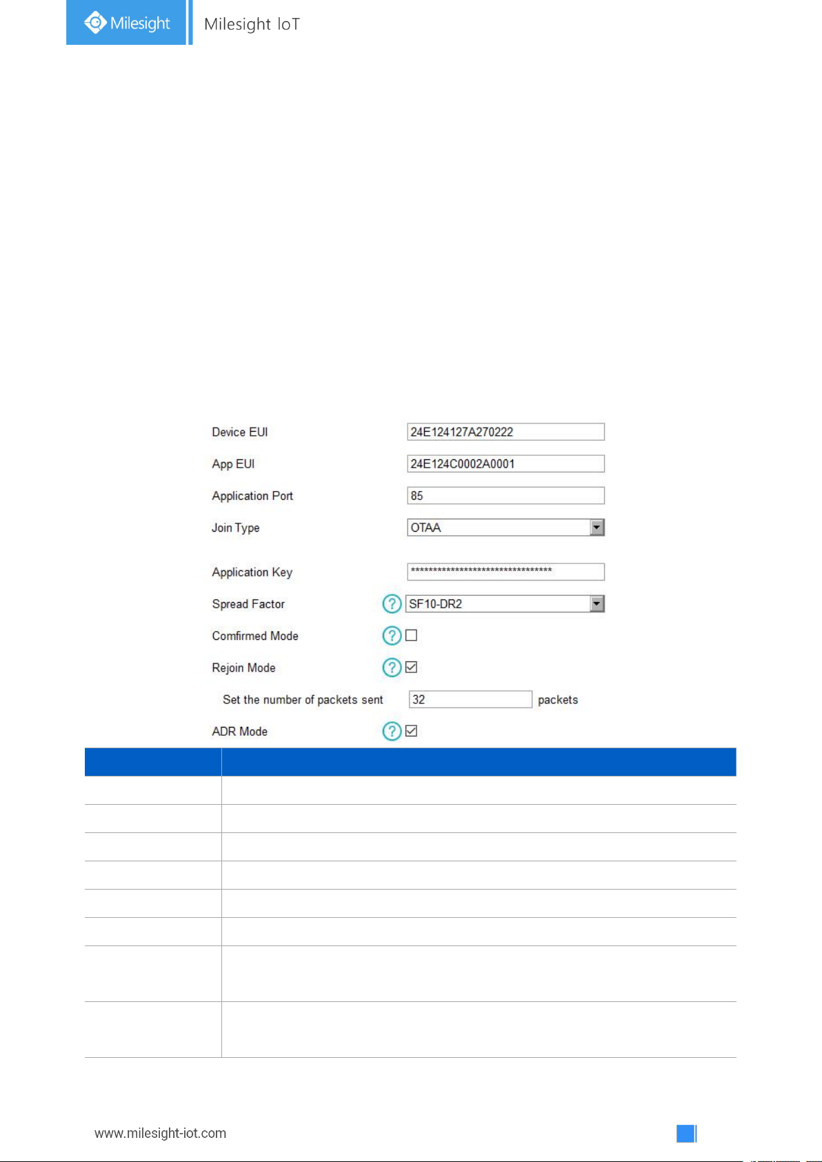
WS101 can be configured via NFC-enabled smartphone.
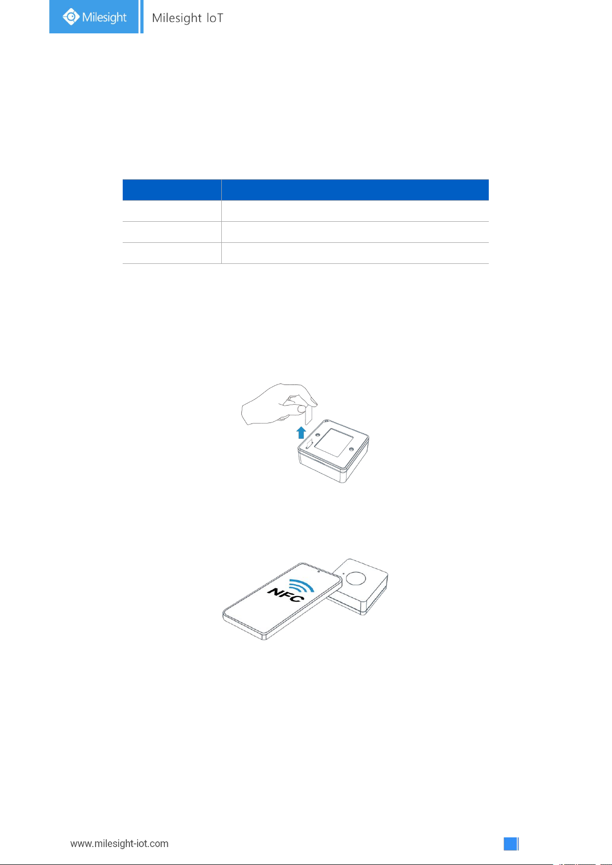
1. Pull out the battery insulating sheet to power on the device. The indicator will light up in green for 3
seconds when device turns on.
2. Download and install “Milesight ToolBox” App from Google Play or App Store.
3. Enable NFC on the smartphone and open Milesight ToolBox.
4. Attach the smartphone with NFC area to the device to read device information.
5. Basic information and settings of devices will be shown on ToolBox if it’s recognized
successfully. You can read and configure the device by tapping the Read/Write button on the
App. In order to protect the security of devices, password validation is required when configuring
via a new smartphone. Default password is 123456.
Note:
1) Ensure the location of smartphone NFC area and it’s recommended to take off phone case.
Page 7
7
2) If the smartphone fails to read/write configurations via NFC, move the phone away and back
Parameters
Description
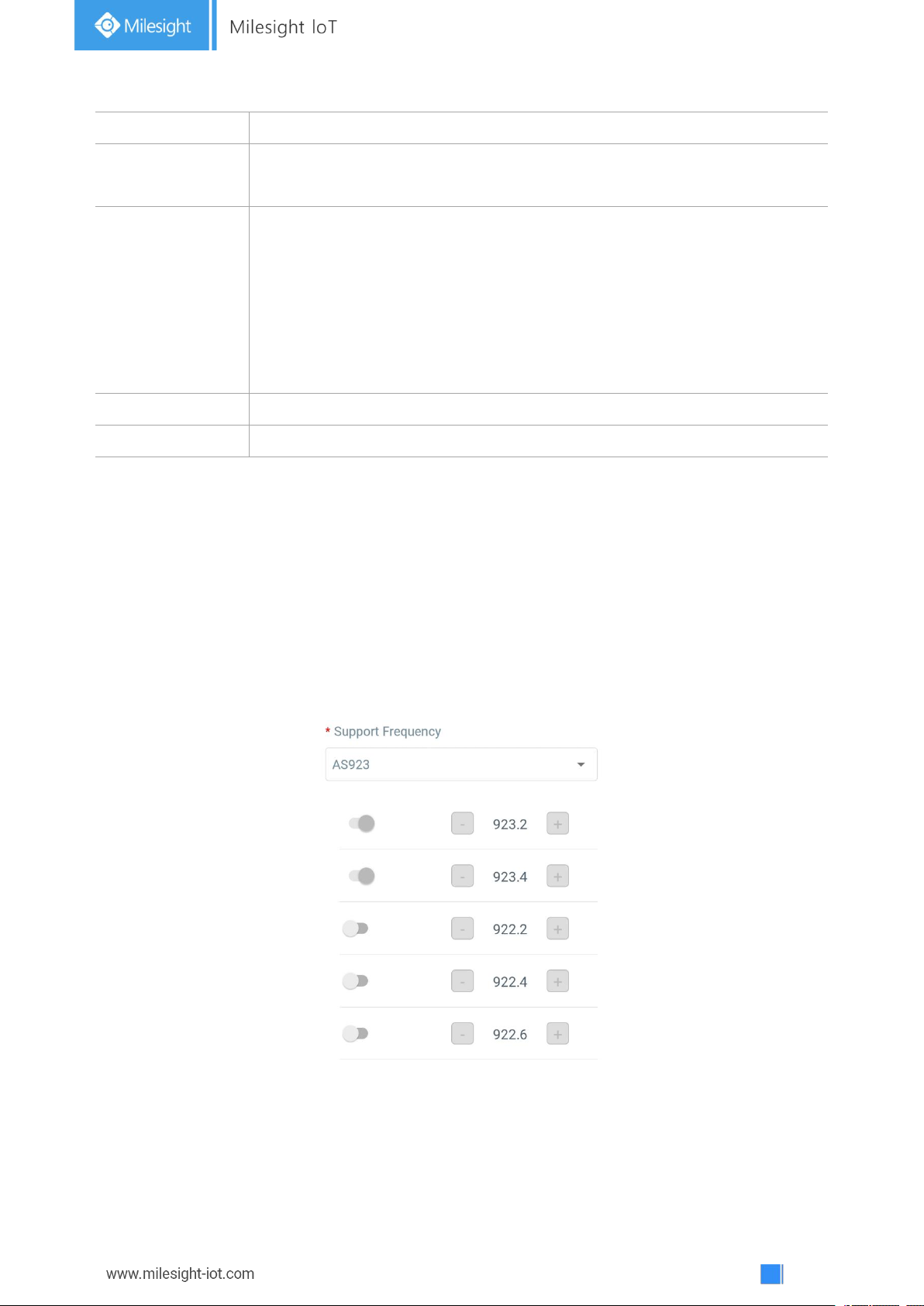
Device EUI
Unique ID of the device which can also be found on the label.
App EUI
Default App EUI is 24E124C0002A0001.
Application Port
The port used for sending and receiving data, default port is 85.
Join Type
OTAA and ABP modes are available.
Application Key
Appkey for OTAA mode, default is 5572404C696E6B4C6F52613230313823.
Device Address
DevAddr for ABP mode, default is the 5thto 12thdigits of SN.
Network Session
Key
Nwkskey for ABP mode, default is 5572404C696E6B4C6F52613230313823.
Application
Session Key
Appskey for ABP mode, default is 5572404C696E6B4C6F52613230313823.
to try again.
3) WS101 can also be configured by ToolBox software via dedicated NFC reader provided by
Milesight IoT, you can also configure it via TTL interface inside the device.
3.3 LoRaWAN Settings
LoRaWAN settings are used for configuring the transmission parameters in LoRaWAN®network.
Basic LoRaWAN Settings:
Go to Device -> Setting -> LoRaWAN Settings of ToolBox App to configure join type, App EUI,
App Key and other information. You can also keep all settings by default.
Page 8
8
Spread Factor
If ADR is disabled, the device will send data via this spread factor.
Confirmed Mode
If the device does not receive ACK packet from network server, it will resend
data 3 times at most.
Rejoin Mode
Reporting interval ≤ 30 mins: device will send specific mounts of LoRaMAC
packets to check connection status every 30 mins; If no reply after specific
packets are being sent, the device will re-join.
Reporting interval > 30 mins: device will send specific mounts of LoRaMAC
packets to check connection status at every reporting interval; If no reply after
specific packets are being sent, the device will re-join.
ADR Mode
Allow network server to adjust datarate of the device.
Tx Power
Transmit power of device.
Note:
1) Please contact sales representative for device EUI list if there are many units.
2) Please contact sales representative if you need random App keys before purchase.
3) Select OTAA mode if you use Milesight IoT Cloud to manage devices.
4) Only OTAA mode supports rejoin mode.
LoRaWAN Frequency Settings:
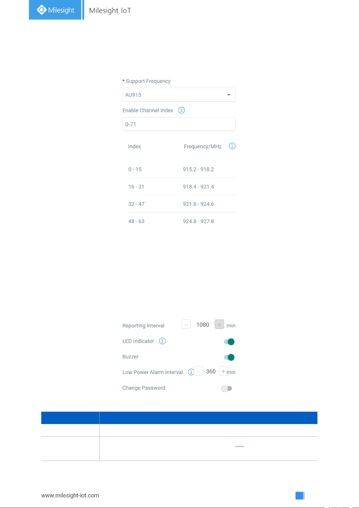
Go to Setting->LoRaWAN Settings of ToolBox App to select supported frequency and select
channels to send uplinks. Make sure the channels match the LoRaWAN®gateway.
If device frequency is one of CN470/AU915/US915, you can enter the index of the channel that
you want to enable in the input box, making them separated by commas.
Examples:
1, 40: Enabling Channel 1 and Channel 40
1-40: Enabling Channel 1 to Channel 40
Page 9
9
1-40, 60: Enabling Channel 1 to Channel 40 and Channel 60
Parameters
Description
Reporting Interval
Reporting interval of battery level to network server. Default: 1080min
LED Indicator
Enable or disable the light indicating in chapter 2.4.
Note: The indicator of reset button is not allowed to disable.
All: Enabling all channels
Null: Indicates that all channels are disabled
Note:
For -868M model, default frequency is EU868;
For -915M model, default frequency is AU915.
3.4 General Settings
Go to Device->Setting->General Settings of ToolBox App to change the reporting interval, etc.
Page 10
10
Buzzer
The buzzer will be triggering together with indicator if the device is
registered to network.
Low Power Alarm
Interval
The button will report low power alarms according to this interval when the
battery is lower than 10%.
Change Password
Change the password for ToolBox App to write this device.
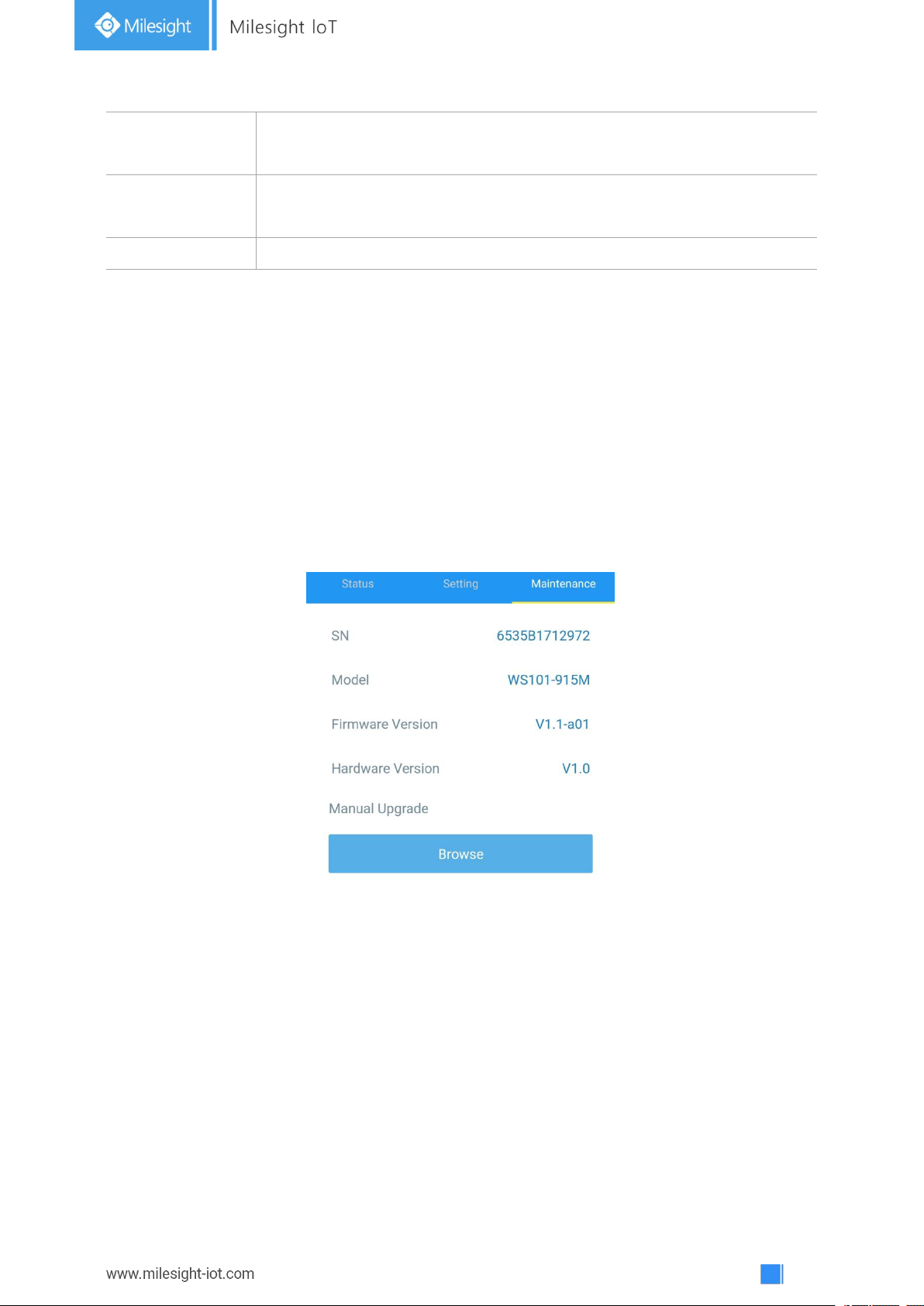
3.5 Maintenance
3.5.1 Upgrade
1. Download firmware from Milesight website to your smartphone.
2. Open ToolBox App and click “Browse” to import firmware and upgrade the device.
Note:
1) Operation on ToolBox is not supported during upgrade.
2) Only Android version ToolBox supports the upgrade feature.
3.5.2 Backup
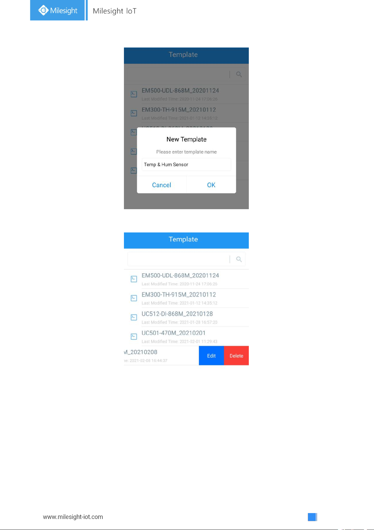
WS101 supports configuration backup for easy and quick device configuration in bulk. Backup is
allowed only for devices with the same model and LoRa frequency band.
1. Go to “Template” page on the App and save current settings as a template. You can also edit
the template file.
2. Select one template file that saved in the smartphone and click “Write”, then attach it to
another device to write configuration.
Page 11
11
Note: Slide the template item to the left to edit or delete the template. Click the template to edit
the configurations.
3.5.3 Reset to Factory Default
Please select one of the following methods to reset device:
Via Hardware: Hold on the reset button for more than 10s. After reset complete, the indicator
will blink in green twice and device will reboot.
Via ToolBox App: Go to Device -> Maintenance to tap “Reset”, then attach smartphone with NFC
area to device to complete reset.
Page 12
12
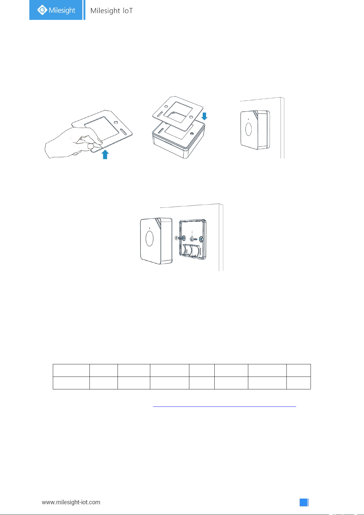
4. Installation
Channel1
Type1
Data1
Channel2
Type2
Data2
Channel 3
...
1 Byte
1 Byte
N Bytes
1 Byte
1 Byte
M Bytes
1 Byte
...
3M Tapes Fix:
Paste 3M tape to the back of the button, then tear the other side and place it on a flat surface.
Screw Fix:
Remove the back cover of the button, screw the wall plugs into the wall and fix the cover with
screws on it, then install back the device.
Lanyard:
Pass the lanyard through the aperture near the edge of the button, then you can hang the button
onto keychains and the like.
5. Device Payload
All data are based on the following format(HEX):
For decoder examples you can find at https://github.com/Milesight-IoT/SensorDecoders.
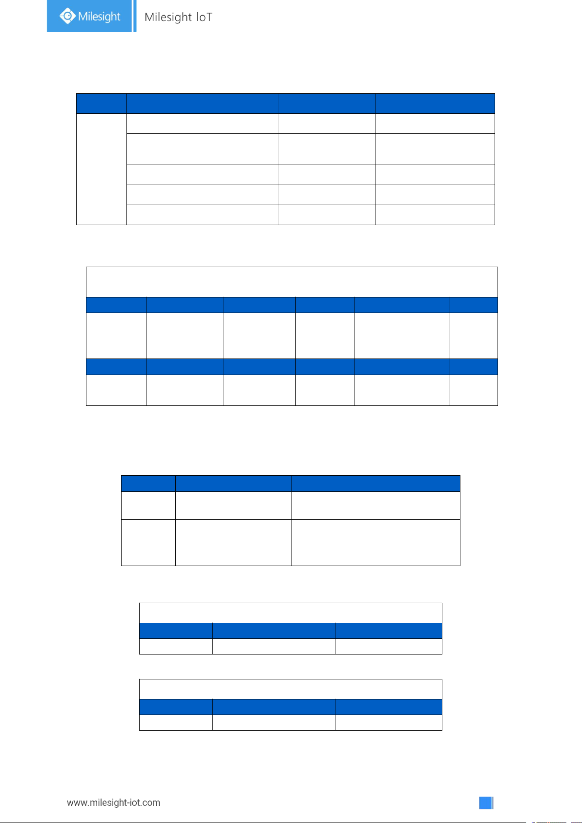
5.1 Basic Information
WS101 reports basic information of button every time joining the network.
Page 13
13
Example:
Channel
Type
Data Example
Description
ff
01(Protocol Version)
01
V1
08(Device SN
)
61 27 a2 17 41 32
Device SN is
6127a2174132
09 (Hardware Version)
01 40
V1.4
0a (Software Version)
01 14
V1.14
0f(Device Type)
00
Class A
ff 09 01 00 ff 0a 01 02 ff 0f 00
Channel
Type
Value
Channel
Type
Value
ff09(Hardware
version)
0100 (V1.0)
ff
0a
(Software version)
0102
(V1.2)
Channel
Type
Value
ff
0f
(Device Type)
00
(Class A)
Channel
Type
Description
01
75(Battery Level)
UINT8, Unit: %
ff
2e(Button Message)
01: Mode 1(short press)
02: Mode 2 (long press)
03: Mode 3 (double press)
01 75 64
Channel
Type
Value
01
75 (Battery)
64 => 100%
ff 2e 01
Channel
Type
Value
ff
2e(Button Message)
01 => short press
5.2 Button Message
WS101 reports battery level according to reporting interval (1080 mins by default) and button
message when button is pressed.
Example:
Page 14
14
5.3 Downlink Commands
Channel
Type
Data Example
Description
ff
03(Set Reporting Interval)
b0 04
b0 04 => 04 b0 = 1200s
WS101 supports downlink commands to configure the device. Application port is 85 by default.
-END-
 Loading...