

Page 1
Page 2

2
Contents
1. Preface
2. Introduction
3. Installation
4. Configuration
5. Application Examples
.............................................................................................................................................
....................................................................................................................................
2.1 Features
2.2 Parameters
2.3 LED Indicator Description
3.1 Environment
3.2 Power Supply
3.3 Micro USB Port
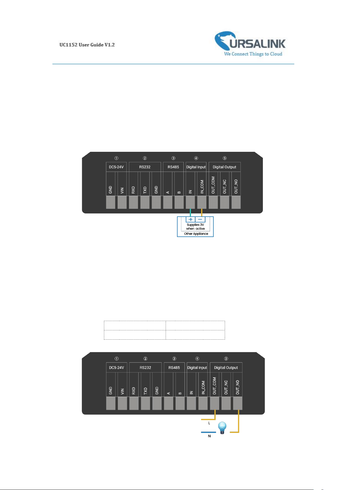
3.4 Terminal Description
3.5 Digital Input
3.6 Relay Output
4.1 Configuration via PC
4.1.1 Serial Port Settings
4.2 Status
4.3 General
4.3.1 Basic
4.3.2 RS485
4.2.3 RS232
4.4 LoRaWAN
4.4.1 Basic
4.4.2 Channel
4.4.3 Advanced
4.5 Channel
4.6 Command
4.6.1 Read Command from Device
4.6.2 Open a Command File
4.6.3 Save the Command to Device
4.6.4 Save the Command as File
4.7 IF-THEN Behaviour Command
4.7.1 Supported IF Condition
4.7.2 Supported THEN Actions
4.8 Upgrade
5.1 Send an Alert When Channel Value Exceeds a Certain Threshold
.................................................................................................................................
............................................................................................................................
......................................................................................................
......................................................................................................................................
..........................................................................................................................
.........................................................................................................................
......................................................................................................................
.............................................................................................................
...........................................................................................................................
..........................................................................................................................
..................................................................................................................................
..............................................................................................................
...................................................................................................
...................................................................................................................................
................................................................................................................................
..........................................................................................................................
........................................................................................................................
........................................................................................................................
.............................................................................................................................
..........................................................................................................................
.....................................................................................................................
..................................................................................................................
................................................................................................................................
............................................................................................................................
...................................................................................
..............................................................................................
..................................................................................
.......................................................................................
.............................................................................................
............................................................................................
..........................................................................................
...............................................................................................................................
...................................................................................................................
.....................................
3
3
3
4
4
5
5
5
6
6
7
7
9
9
10
11
12
12
13
14
15
15
17
19
21
22
23
23
23
23
23
24
27
28
29
29
Page 3

3
1. Preface
Thank you for choosing Ursalink UC1152 LoRa Remote I/O. This user guide will present in detail
all the functions and features of the product. Ursalink UC1152 is designed for both industrial and
commercial applications. The product should be used under the guidance of this user guide,
referring to parameters and technical specifications. The UC1152 is a compact, high-performance
device that offers LoRaWAN connectivity for data transmission.
We bear no liability for property loss or physically injury arising from abnormal or incorrect usage
of this product.
2. Introduction
Ursalink UC1152 is designed as a cost-effective industrial machine monitoring device that
monitors and controls up to 1 RS485, 1 RS232, 1 DC signal and 1 drivable relay output.
With the aid of Ursalink UC1152, the alarm condition brings attention to engineering personnel
immediately. The output can be connected with an alarm indication device, such as a light or
horn.
The module can give immediate response to the status of both the input and output conditions.
A LoRa module is embedded in the Ursalink UC1152 .
This user guide is intended to provide detailed technical specifications and explanations to the
basic user as well as the technically-minded groups. It is a live document, and will be updated
from time to time. Please ensure that you have the latest version, by checking our website at:
https://www.ursalink.com/en/documents-download/
2.1 Features
1 relay drivable output
1 digital input connected with 1 DC signal
Offer serial interface with 1 RS232 and 1 RS485
Collects data from Modbus slave device
Integrate legacy serial and I/O devices into cloud
Customizable conditions & programmable actions
Send uplink alert messages according to user-defined conditions
Automatic switching of field devices at set times
Comply with the LoRaWAN Class C protocol
Support star network and mesh network
High Rx sensitivity and adjustable Tx power
Page 4
4
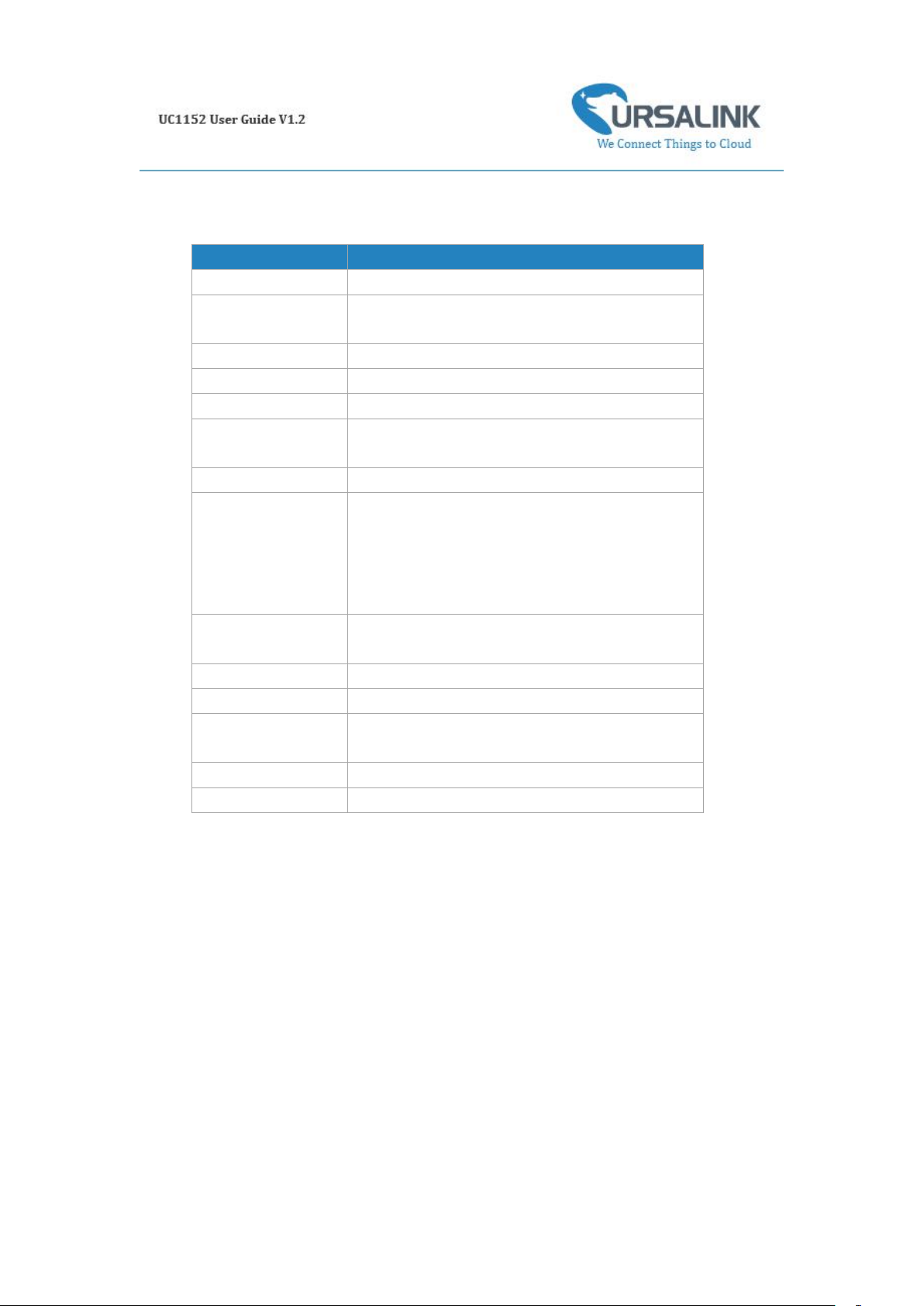
2.2 Parameters
Parameter Item
Reference Scope
Antenna
50 Ω SMA Antenna Interface
Frequency Band
EU 433, CN 470-510, EU 863-870, IN865, US
902-928, AU 915-928, KR 920-923
Sensitivity
-147 dBm @300bps
Output Power
20dBm
Protocol
LoRaWAN Class C
RS485
Baud rate: 2400-115200bps
Protocol: Modbus RTU
RS232
Baud rate: 4800-115200bps
Digital Input
Opto-isolated depending on voltage
Can accept any DC signals of any type,including:
➢ Dry Contacts ➢ DC Voltage (3 - 20V)
High Voltage: +3V ~ +24V
Low Voltage: +1V max
Digital Output
1 x SPDT Relay Contact Rating:
Maximum Load Current: 250VAC/30VDC@3A
Connector type
Screw Terminals
DC Power Supply
5-24 VDC
Operating
Temperature
-40°C to +70°C (-40°F to +158°F)
Relative Humidity
0% to 95% (non- condensing)
Dimensions
79 x 60 x 24 mm
2.3 LED Indicator Description
System:
Solid On: System booting
On for 500ms, off for 500ms: Working properly
On for 100ms, off for 100ms: Failed to send data
ACT:
Off: Failed to join network
On for 75ms, off for 3000ms: Joined the network successfully
On for 500ms, off for 500ms: Sending/Receiving data
Page 5
5
3. Installation
3.1 Environment
Due to the product properties of UC1152, we STRONGLY advise that it should not be installed in
proximity to a variable speed drive or with any other electrically noisy equipment. DO NOT install
UC1152 into a metal enclosure unless an antenna is mounted on the outside of the enclosure.
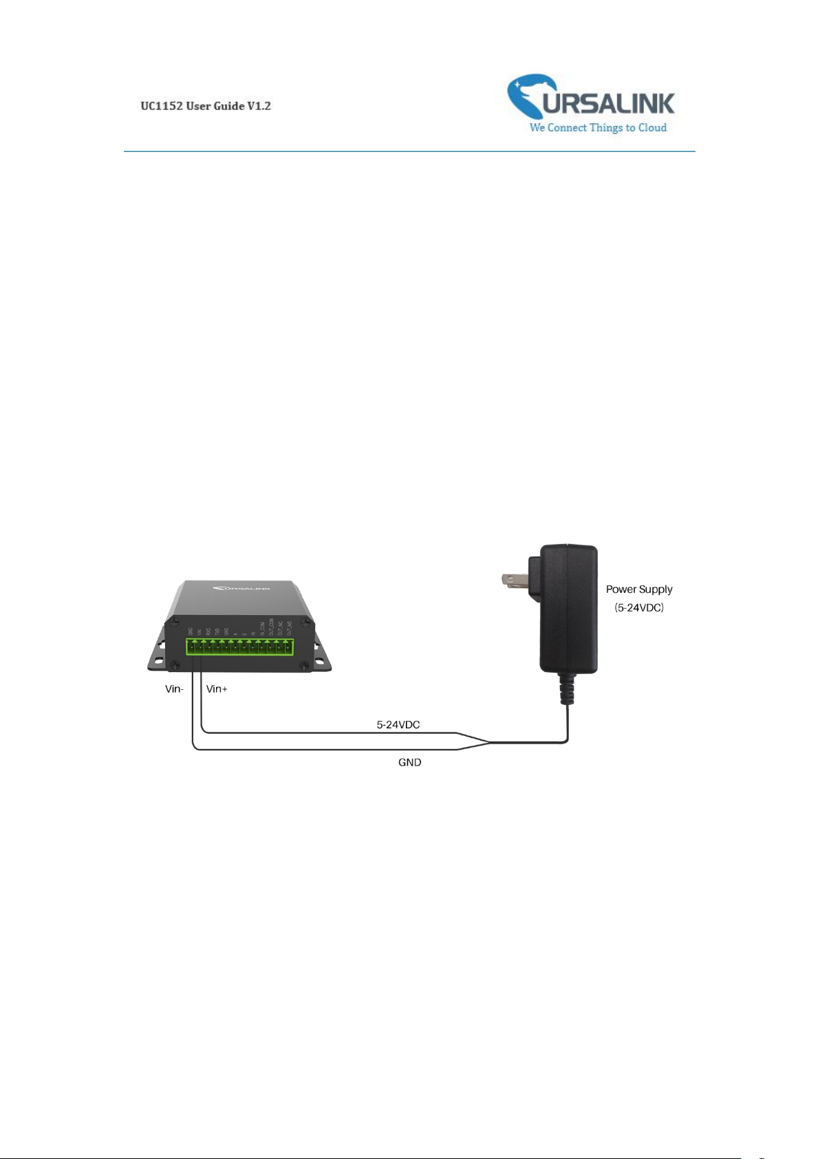
3.2 Power Supply
UC1152 features a 2 pin 3.5mm terminal block where a power supply can be connected. The
power supply should have the following specifications:
Output Voltage: 12V nominal
Output Current: 0.5A
Installation:
For industrial applications, it is advised that UC1152 should be installed into its own metal
housing and be powered from a separate power supply (as opposed to sharing one with other
equipment).
Please Note: While UC1152 has fairly rugged internal power supply circuitry, no special provision
for lightning protection is well in place. If UC1152 is used in an area where thunderstorm is about
to occur, it is advisable to use a commercially available lightning suppressor (the same applies to
inputs or outputs that are connected to wires longer than 2 or 3 meters). The guarantee does not
cover damage resulting from lightning strikes! UC1152 can operate reliably from voltages in the
range of 5 to 24 VDC.
Page 6
6
3.3 Micro USB Port
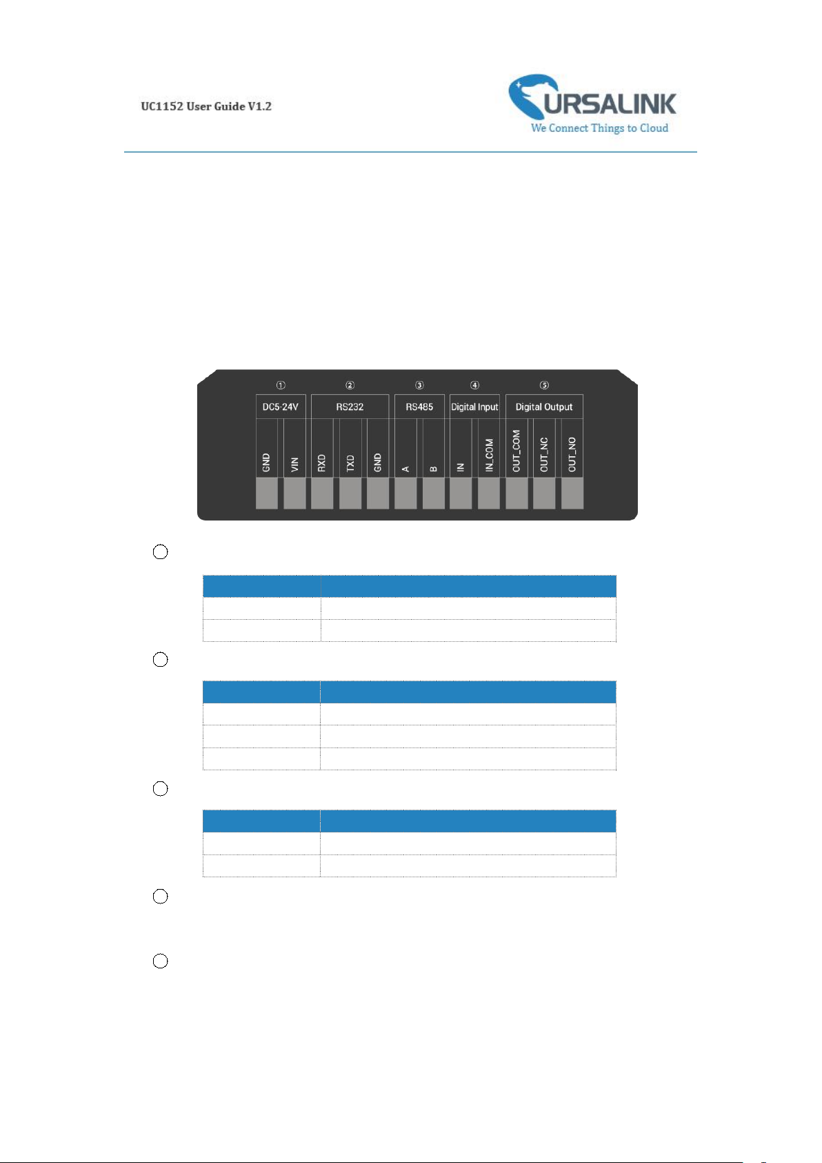
Terminal
Description
VIN
Positive terminal of the DC power supply (+)
GND
Negative terminal of the DC power supply (-)
Terminal
Description
RXD
Receive Data
TXD
Transmit Data
GND
Ground
Terminal
Description
A
Data +
B
Data -
UC1152 provides a micro USB port to connect to a PC via USB cable, which allows the PC to
configure the unit.
3.4 Terminal Description
1
[DC 5-24V]
2
[RS232]
3
[RS485]
4
[Digital Input]
Opto-isolated depending on voltage DC Voltage (3-24V)
5
[Digital Output]
Driving relay to connect NC or NO
Page 7
7
3.5 Digital Input
Maximum Current
3 Amp
Maximum Voltage
250VAC, 30VDC
When the input is triggered either as high or low, UC1152 will take action if you have
pre-configured related command.
Terminal "IN" is internally pulled high. Leaving the connection open or connecting it to "0 -1
V"will indicate an "Input-De-activate" state.
When terminal "IN" is connected to "3-24 V", it will indicate an "Input-Activate" state.
Trigger voltage: Minimum = 3 VDC, Maximum = 24 VDC.
3.6 Relay Output
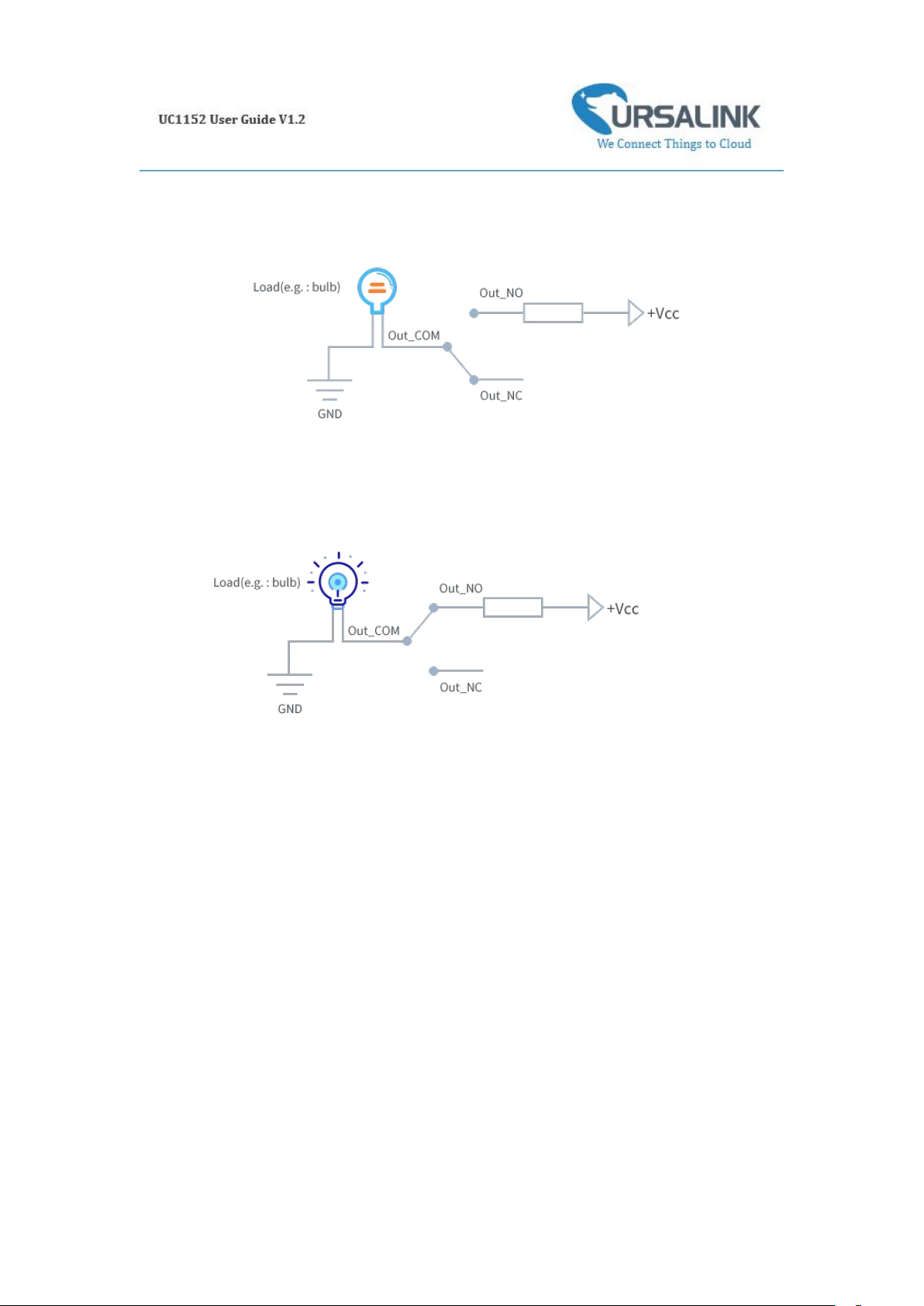
The output is used for switch circuits ON & OFF and can be controlled by command message
The output terminals are internally connected to a 3 Amp SPDT relay
OUT_NC = Normally Closed
OUT_COM = Common
OUT_NO = Normally Open
Page 8
8
When the output is off, the COM and N/C terminals will be internally connected to each
other. Here is a schematic of the output circuit:
When the output is on, the COM and N/O terminals will be internally connected to each
other. Here is a schematic of the output circuit:
Page 9
9
4. Configuration
4.1 Configuration via PC
Follow these steps:
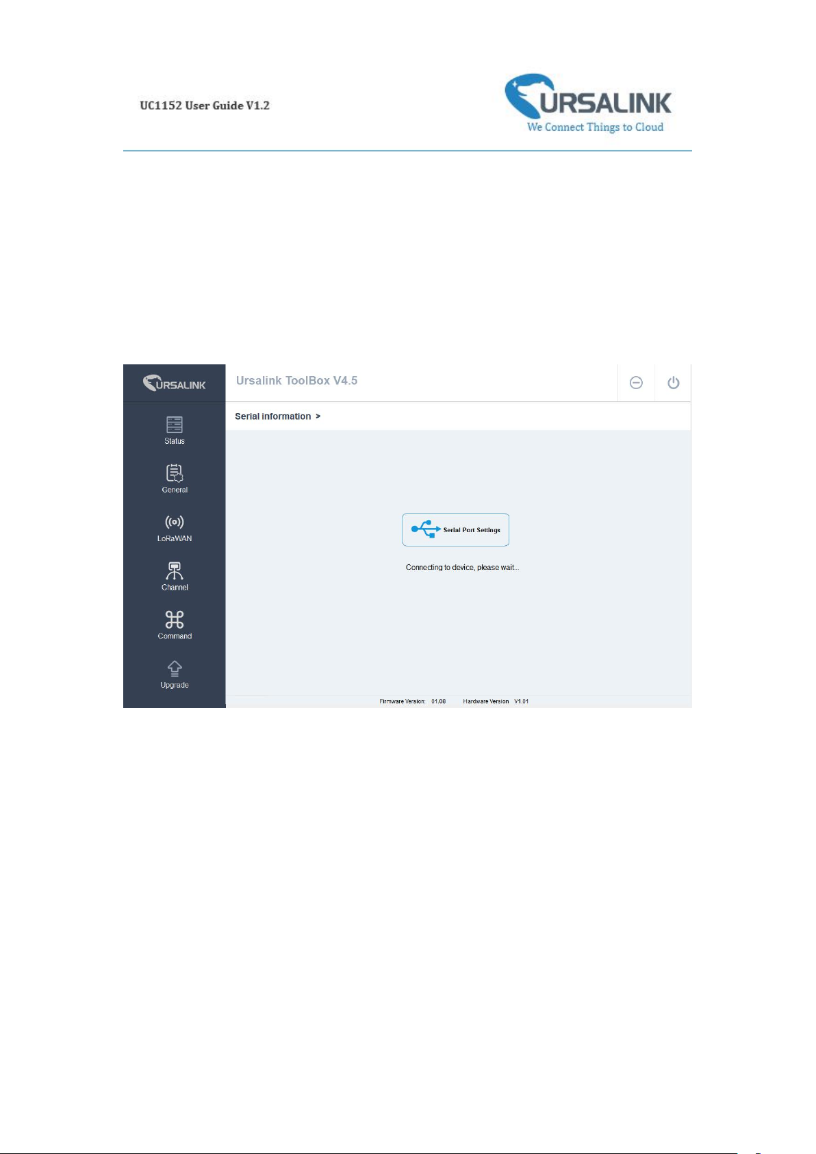
Step 1: Connect UC1152 to PC via micro USB port.
Step 2: Power on UC1152.
Step 3: Run the Ursalink ToolBox.
The software will display this interface when getting started. Here you can create a new setup,
import an existing setup from your PC, or retrieve the current setup from UC1152.
Page 10
10
4.1.1 Serial Port Settings
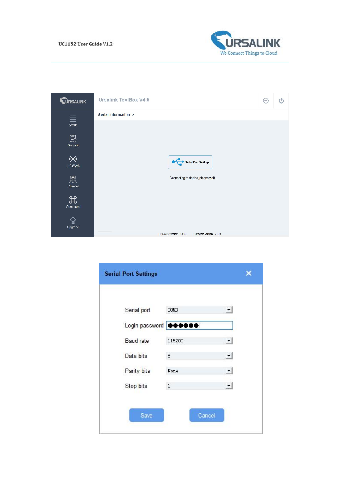
When the Ursalink ToolBox displays: Connecting to device, please wait...
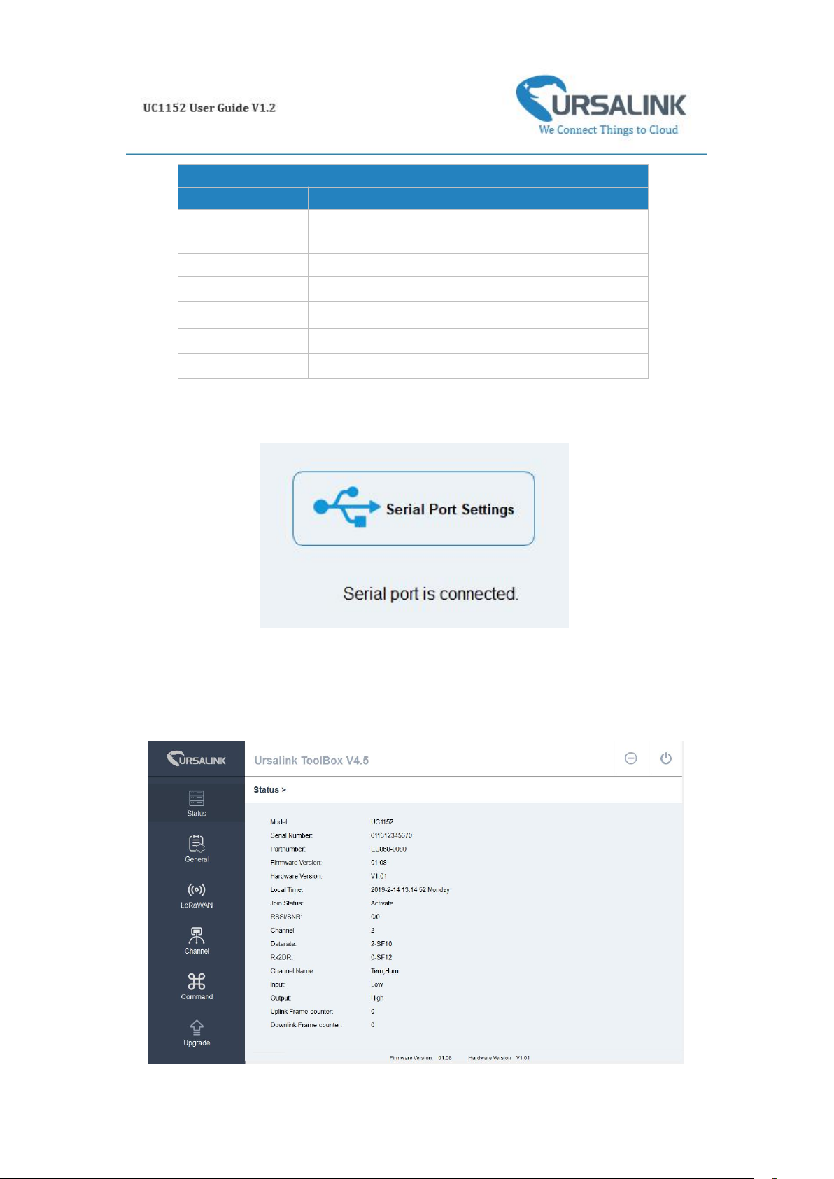
You can click Serial Port Settings to set the correct serial port parameters.
Page 11
11
If both the serial port parameters and the login password are correct, it will display: Serial port is
Serial Port Settings
Item
Description
Default
Serial Port
Select the serial port for data
transmission.
Null
Login Password
Enter the login password.
123456
Baud Rate
Select from "9600", "57600", "115200".
115200
Data Bits
Select from "5", "7", "8".
8
Parity Bits
Select from "Even", "Odd", "None".
None
Stop Bits
Select from "1", "2".
1
connected.
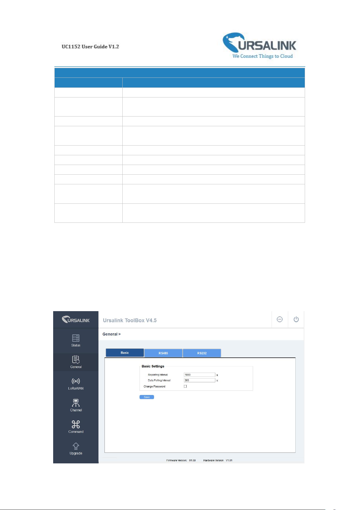
4.2 Status
Click "Status" to see the basic status information of this device:
Page 12
12
Status
Item
Description
Local Time
Show the time of the device.
Join Status
Show if the device joined the network successfully.
The "Activate" means the device has joined the network.
RSSI/SNR
Show the RSSI/SNR of received packet.
Channel
Show the the channel currently used by the device to send
packets.
Rx2DR
Show the RX2 datarate which used for the RX2 receive-window.
Channel
Show the name of the channel that users have created.
Input
Show the status of Digital Input.
Output
Show the status of Digital Output.
Uplink Frame-counter
The number of data frames sent uplink from UC1152 to the
network server.
Downlink
Frame-counter
The number of data frames sent downlink from the network
server to UC1152.
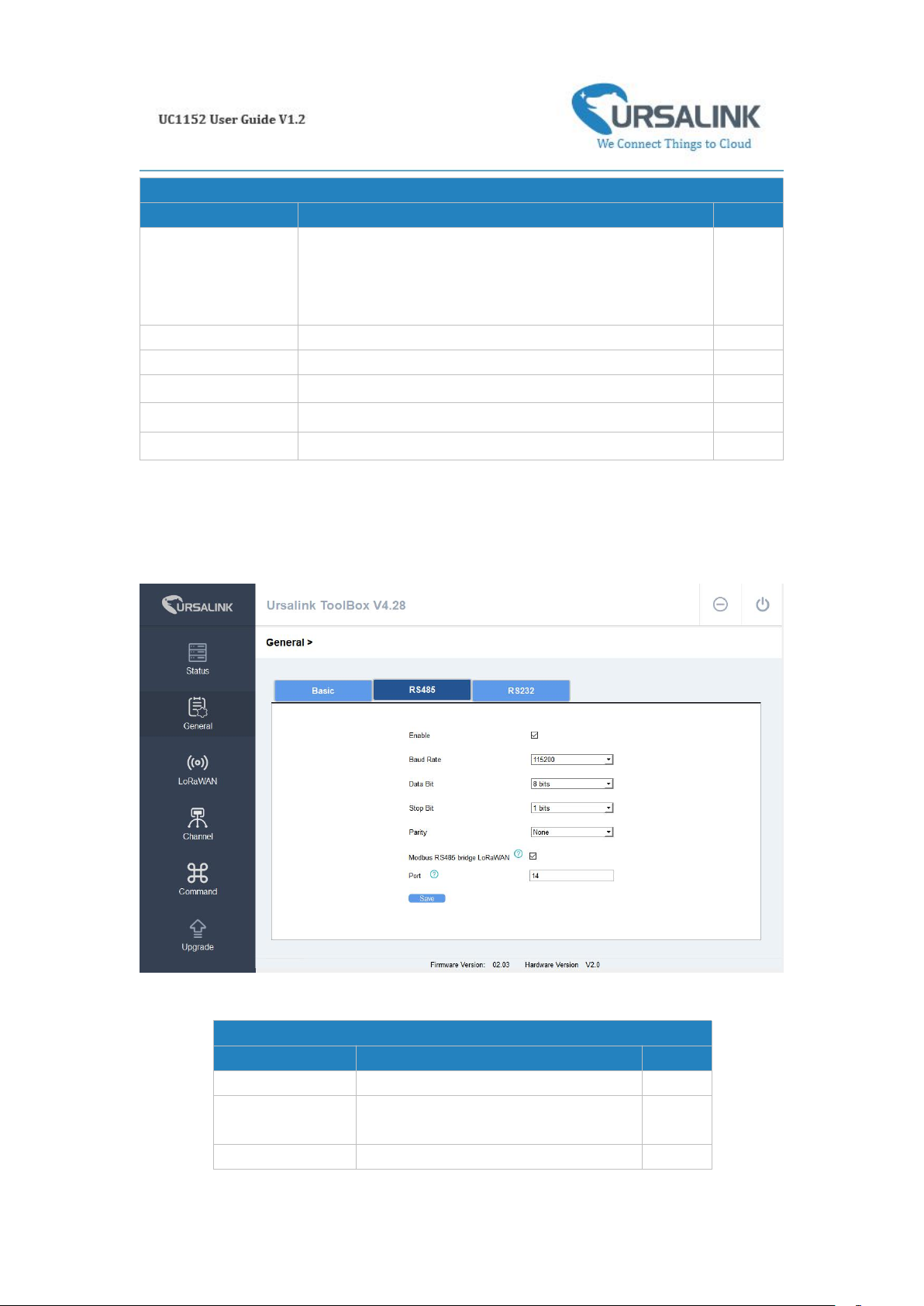
4.3 General
Click "General" to set the general settings of the device
4.3.1 Basic
Page 13
13
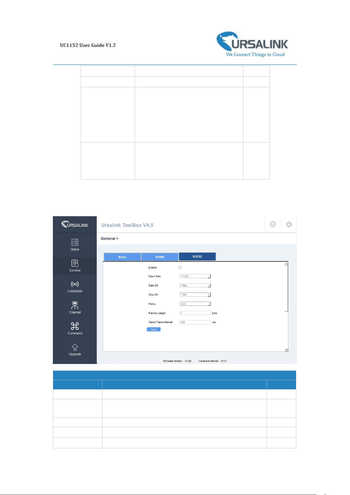
4.3.2 RS485
Basic Setting
Item
Description
Default
Reporting Interval
Set the regular report interval.
The device will send the I/O status/value and signal
strength to the user-built server regularly.
The interval range is 1-3600 seconds.
1800
Data Polling Interval
The interval of reading data from analog input.
360
Change Password
Click to change password.
Null
Old Password
Enter the old password.
Null
New Password
Enter the new password.
Null
Confirm Password
Enter the new password again.
Null
485 Settings
Item
Description
Default
Enable
Enable/disable RS485.
Enable
Baud Rate
Select from "2400", "4800", "9600",
"19200", "38400", "57600", "115200".
9600
Data Bits
Select from "5", "7", "8".
8
Page 14
14
4.2.3 RS232
Stop Bits
Select from "1", "2".
1
Parity Bits
Select from "Even", "Odd", "None".
None
Modbus RS485
bridge LoRaWAN
Enable this mode to collect data from
slave devices and then send it to
Network Server via LoRaWAN.
This mode also has the capability to
change the behaviour of the ModBus
device by writing into its registers.
Disable
Port
Eenter the LoRaWAN frame port for
transparent transmission between
UC11-N1 and Network Server.
Range: 2-84,86-223.
Null
232 Settings
Item
Description
Default
Enable
Enable/disable RS232.
Disabled
Baud Rate
Select from "4800", "9600", "19200", "38400", "57600",
"115200".
115200
Data Bits
Select from "7", "8".
8
Stop Bits
Select from "1", "2".
1
Parity Bits
Select from "Even", "Odd", "None".
None
Page 15
15
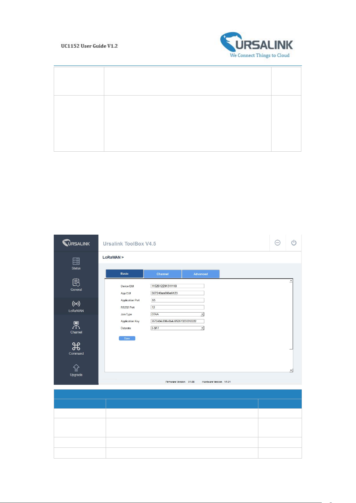
4.4 LoRaWAN
Basic Settings
Item
Description
Default
Device EUI
Enter the identifier of the gateway.
Model + SN
App EUI
An AppEUI that will be attached to received packets
and a Join EUI.
24e124c0002
a0002
Application Port
The port used by the device to send and receive data.
85
RS232 Port
The port is used for RS232 transparent transmission.
86
Packet
Length(Bytes)
Set the length of the serial data frame. Packet will be sent out
when preset frame length is reached. The range is 1-1024, the
unit is byte.
256
Serial Frame
Interval(ms)
The interval that the device sends out real serial data stored in
the buffer area to public network. The range is 10-65535
milliseconds.
Note: data will be sent out to public network when real serial
data size reaches the preset packet size, even though it's
within the serial frame interval.
100
4.4.1 Basic
Page 16
16
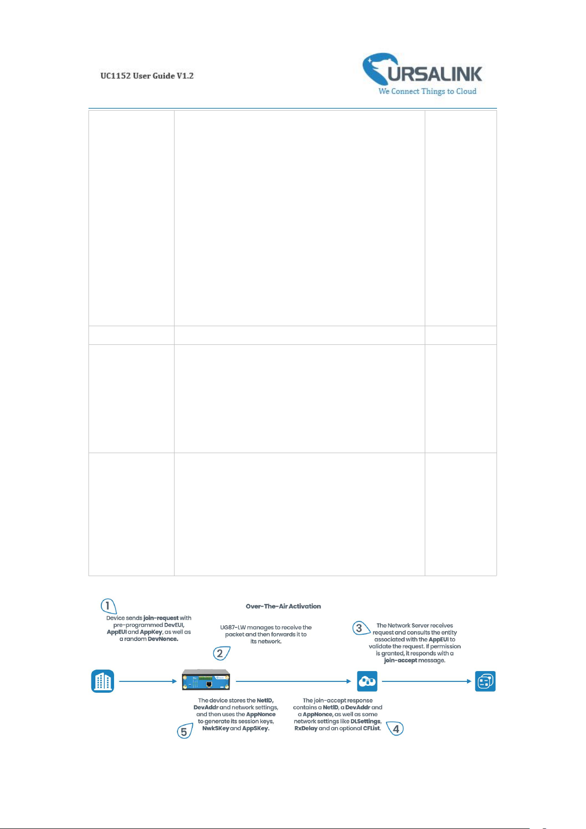
Join Type
Select from: "OTAA" and "ABP".
OTAA: Over-the-Air Activation.
For over-the-air activation, end-devices must follow a
join procedure prior to participating in data
exchanges with the network server.
An end-device has to go through a new join
procedure every time it has lost the session context
information.
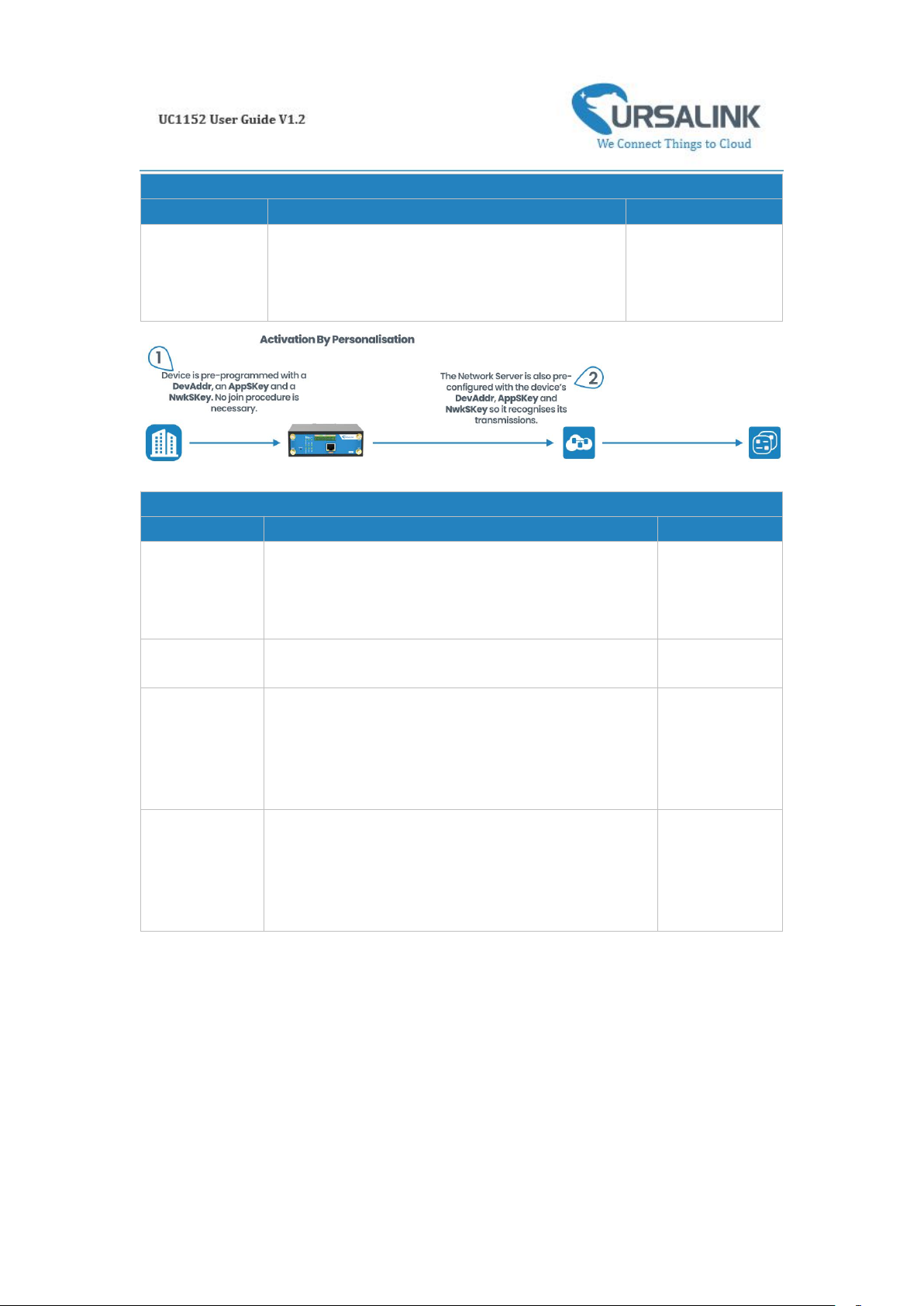
ABP: Activation by Personalization.
Under certain circumstances, end-devices can be
activated by personalization. Activation by
personalization directly ties an end-device to a specific
network by-passing the join request - join accept
procedure.
OTAA
Datarate
The datarate is used to transmit packet.
0-SF12
Regular Report
Confirmed
After sending the regular report packet to the
network server, if the device does not receive ACK bit
from the network server, then the device will resend
the packet.
Note: If the device doesn't receive ACK for a long
time, the device will resend regular report confirmed
packets 3 times at most.
Disabled
Alarm Report
Confirmed
After sending the attribute package or alarm packet to
the network server, if the device does not receive ACK
bit from the Network Server, then the device will
resend the packet.
Note: If the device doesn't receive ACK for a long
time, the device will resend regular report confirmed
packets 3 times at most. However, the device will
resend attribute package all the time.
Disabled
Page 17
17
OTAA Settings
Item
Description
Default
Application Key
Enter the application key. Whenever an
end-device joins a network via over-the-air
activation, the application key is used for derive
the Application Session key.
5572404c696e6b4c
6f52613230313823
ABP Settings
Item
Description
Default
Network ID
Network identifier (NwkID) is used to separate
addresses of territorially overlapping networks of
different network operators and to remedy roaming
issues.
010203
Device Address
Enter the device address. The device address
identifies the end-device within the current network.
The last 8 digits
number of SN
Network
Session Key
Enter the network session key of the device. The
network session key specific for the end-device. It is
used by the end-device to calculate the MIC or part of
the MIC (message integrity code) of all uplink data
messages to ensure data integrity.
5572404c696e
6b4c6f5261323
0313823
Application
Session Key
Enter the application session key of the device. The
AppSKey is an application session key specific for the
end-device. It is used by both the application server
and the end-device to encrypt and decrypt the
payload field of application-specific data messages.
5572404c696e
6b4c6f5261323
0313823
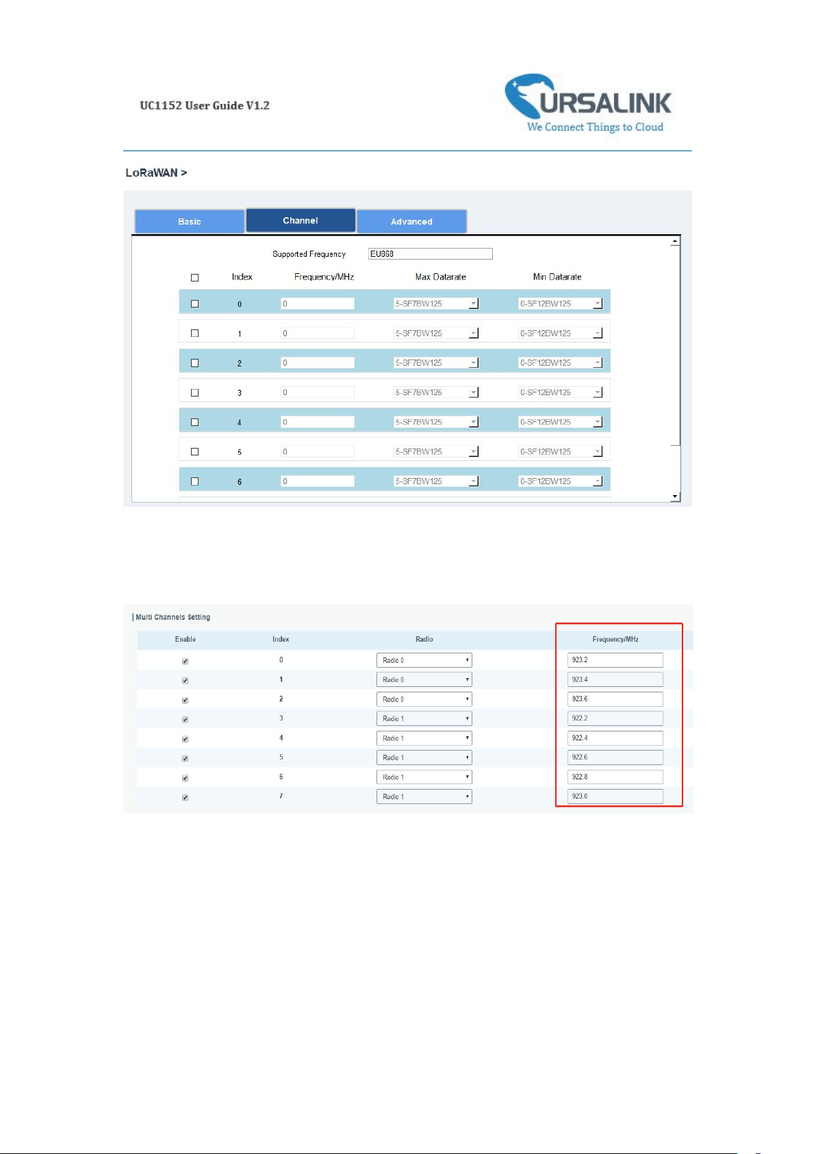
4.4.2 Channel
On this page, you can view all the supported LoRa frequencies and setup the channel frequency
used for receiving and sending data.
Page 18
18
Note: Make sure that you have configured the corresponding channel on the gateway.
E.g. If you have configured a 923.2 MHz channel on UC1152, then you have to configure a 923.2
MHz channel on gateway as well.
Page 19
19
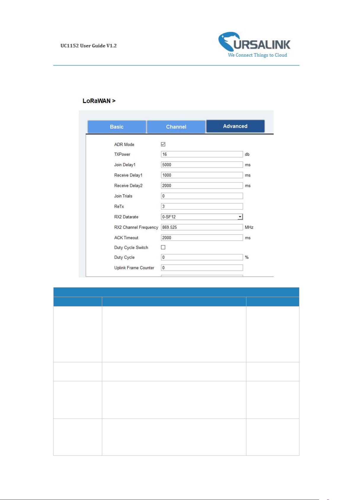
4.4.3 Advanced
Advanced Settings
Item
Description
Default
ADR Mode
ADR Mode: Adaptive Data Rate.
Enabled: The Network Server will adjust the
datarate by MAC command.
Disabled: Whatever how the signal quality is, the
Network Server will not adjust the datarate of
UC1152.
Enabled
TXPower
The TX (transmit power) setting is used to control
the transmission power of the device.
16
Join Delay1
Number of seconds before receive windows are
opened for join.
Specified in the
LoRaWAN
™
Regional
Parameters
Receive Delay1
The Join Accept Delay between the end of the Tx
and the Join Rx Window 1.
Specified in the
LoRaWAN
™
Regional
Parameters
Page 20
20
Receive Delay2
The Join Accept Delay between the end of the Tx
and the Join Rx Window 2.
Specified in the
LoRaWAN
™
Regional
Parameters
Join Trials
The maximum number of the device to resend the
join request when the device failed to join the
network.
0
ReTx
The maximum number of the device to resend the
data packet if no ACK is received after the specified
time.
(Must check Confirmed Mode)
3
RX2
Datarate
Datarate for second receive window, which must be
the same with Tx Datarate of gateway.
0-SF12
RX2 Channel
Frequency
The frequency for second receive window.
Specified in the
LoRaWAN
™
Regional
Parameters
ACK
Timeout
Time in milliseconds to wait for ACK before retry of
confirmed downlink.
2000
Duty Cycle
Switch
Check to enable Duty Cycle.
Disabled
Duty Cycle
Number of minutes in sliding windows for duty
cycle restrictions.
0.
The 0 means
using the
standard Duty
Cycle which is
specified in the
LoRaWAN
™
Regional
Parameters
Uplink Frame
Counter
The number of data frames which sent uplink to the
network server .It will be incremented by the end-d
evice and received by the end-device.
Users can reset the a personalized end-device manu
ally, then the frame counters on the end-device and
the frame counters on the network server for that
end-device will be reset to 0.
0
Downlink
Frame Counter
The number of data frames which received by the e
nd-device downlink from the network server. It will
be incremented by the network server.
Users cloud reset the a personalized end-device ma
0
Page 21
21
nually, then the frame counters on the end-device a
nd the frame counters on the network server for th
at end-device will be reset to 0.
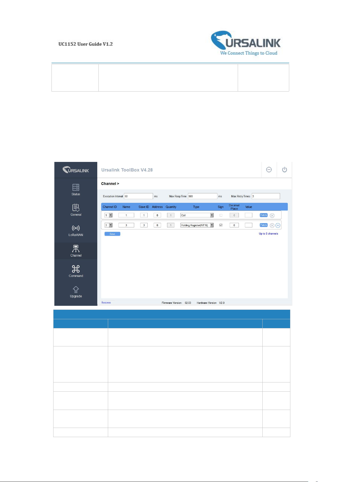
4.5 Channel
Channel Settings
Item
Description
Default
Execution
Interval(ms)
The execution interval between each command. Range:
10-1000. The default value is 50.
50
Max Resp Time(ms)
Set the maximum response time that UC1152 waits for the
response to the command. If the device does not get a
response after the maximum response time, it's determined
that the command has timed out. Range: 10-1000.
500
Max Retry Times
Set the maximum retry times after it fails to read, range: 0-5.
3
Channel ID
Assign the channel for the slave device, 8 channels
selectable.
Null
Name
Set the name to identify the remote channel. It cannot be
blank.
Null
Slave ID
Set Modbus slave ID.
Null
On this page, you can add the channels to poll the remote Modbus Slave.
Page 22
22
You can click to add a channel or click to delete a channel.
Address
The starting address for reading.
Null
Quantity
The device will read 1 digit from starting address.
1
Type
Read command, options are "Coil", "Discrete", "Holding
Register (INT16)", "Input Register (INT16)", "Holding Register
(INT32)", "Input Register (INT32)", "Holding Register (Float)",
"Input Register (Float)", "Input Register (INT32 with upper
16 bits)", "Input Register (INT32 with lower 16bits)","Holding
Register (INT32 with upper 16bits)" and "Holding Register
(INT32 with lower 16bits)" .
Holding
Register
(INT16)
Sign
To identify whether this channel is signed. Default:
Unsigned.
Null
Decimal Place
Used to indicate the decimal place of the channel reading.
For example: the channel value is 1234, and a Decimal Place
is equal to 2, then the actual value is 12.34.
Null
Value
Show the data which read from this slave device.
Null
Fetch
Click to read the data from this slave device.
Null
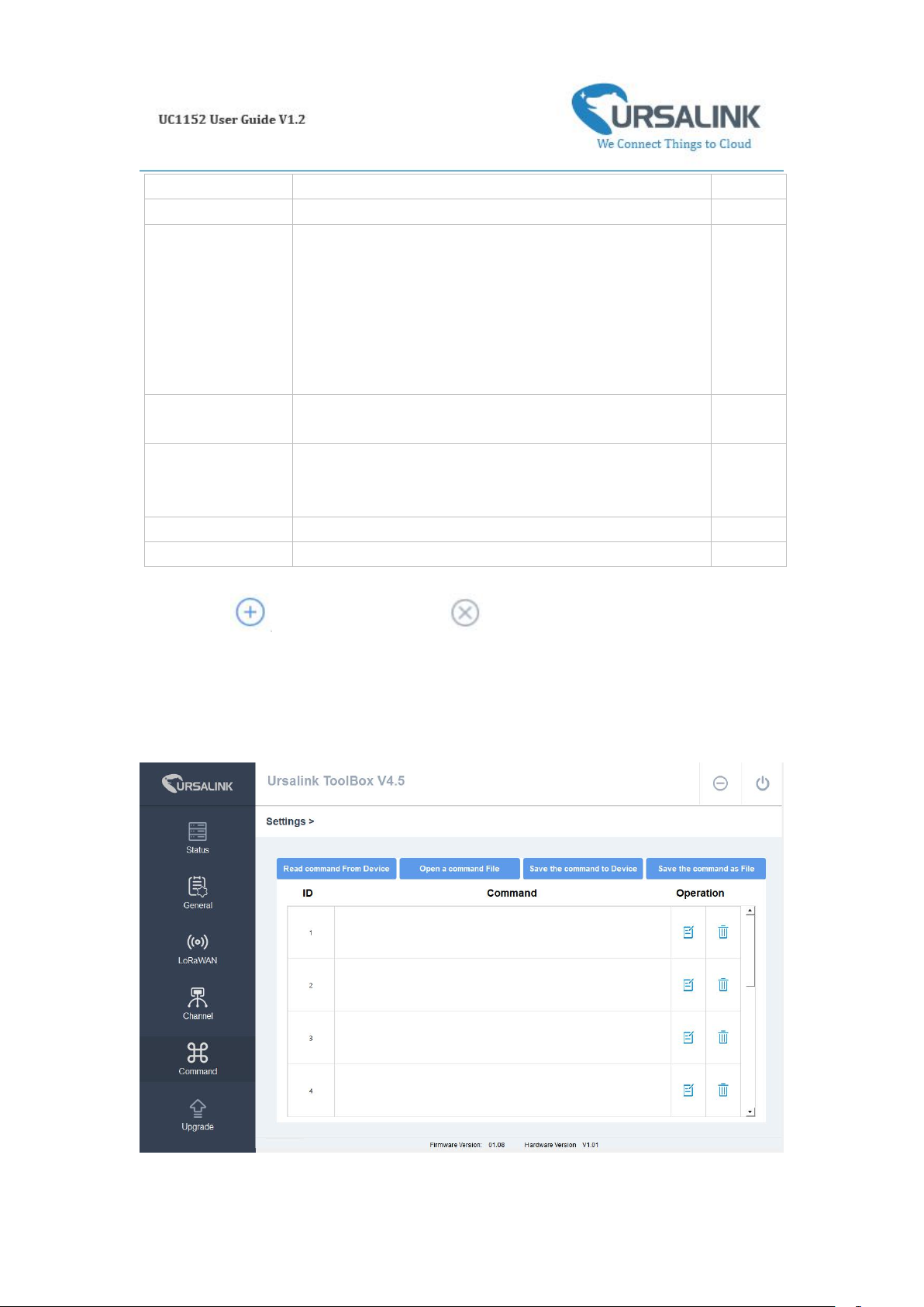
4.6 Command
Page 23
23
4.6.1 Read Command from Device
Click "Command" to go to the configuration page. Ursalink ToolBox will read command from the
connected device automatically. The whole process takes about 5 seconds.
4.6.2 Open a Command File
You can import the existing command file from your PC with following steps.
Step 1: Click "Open a Command File".
Step 2: Select the command file.
4.6.3 Save the Command to Device
You can click "Save the Command to Device" to save the command having been configured on
the Ursalink ToolBox.
4.6.4 Save the Command as File
You can click "Save the Command as File" to save the command having been configured on the
Ursalink ToolBox as a file and save it on your computer.
4.7 IF-THEN Behaviour Command
UC1152 is running with a number of defined behaviour commands. Each command takes the
form of an IF-THEN statement pair. You are thus able to select certain trigger conditions to cause
desired actions. The Ursalink UC1152 allows up to 8 separate behaviour commands with some
models.
Users can select time or input constraints for any IF-THEN statement pairs, so that an action will
only be triggered during certain period within a day, or only if certain input/output conditions are
met.
The user can enter the edit page by clicking , or delete the command by clicking .
Page 24
24
4.7.1 Supported IF Condition
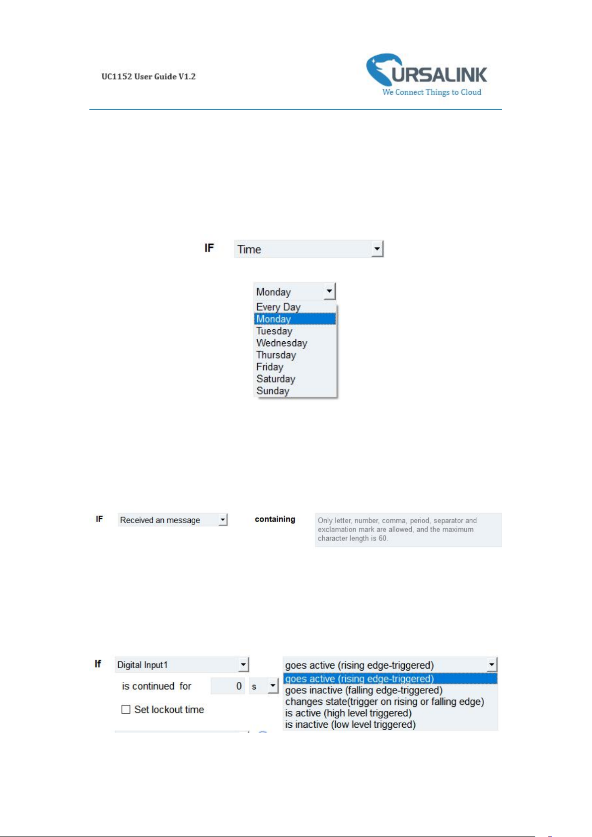
4.7.1.1 IF the Time Is ...
A command containing this IF condition will be triggered at a specific time every day within a
specified range of dates, or on every selected day of the week.
The user can choose the day of the week from:
The user can also set the time from 00:00 to 23:59 on a certain day.
4.7.1.2 IF Received a Specific Message
A command containing this IF condition will be triggered by certain message defined by users.
4.7.1.3 IF Digital Input
A command containing this IF condition will be triggered if the selected digital input changed
according to the specified option.
Page 25
25
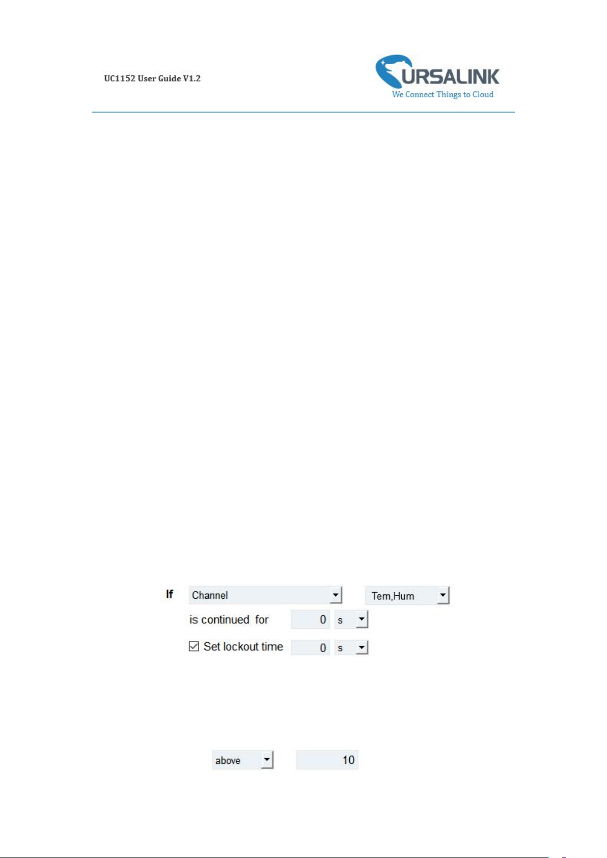
The user can setup multiple combinations; however, digital input 1 be activated before action is
taken.
Then the user can choose from the following options.
• Goes active (rising edge-triggered)
• Goes inactive (falling edge-triggered)
• Changes state (triggered on rising or falling edge)
• Is active (high level triggered)
• Is inactive (low level triggered)
Thus, if the user chooses "Goes Active", then as soon as the specified input changes from inactive
to active, the command will be triggered. Also, it applies to the remaining options when the
preset conditions are met.
The user is also able to specify a "Continued time" for this command, which will not be triggered
until it remains Active or Inactive longer than the time specified. Moreover, the user can specify a
"Lockout time" for this command. After the command has been triggered, it will not be allowed
to be triggered again until the time specified has elapsed.
When you set the time, you can choose the time unit:
Msec: 0-86400000
sec: 0-86400
min: 0-1440
Only integers are allowed. You can't use the decimal point.
Note: There are 3 single actions at most to be executed for a single trigger condition.
4.7.1.4 IF Channel Input
A statement containing this IF condition will be triggered if the value of the channel meets the
specified requirements.
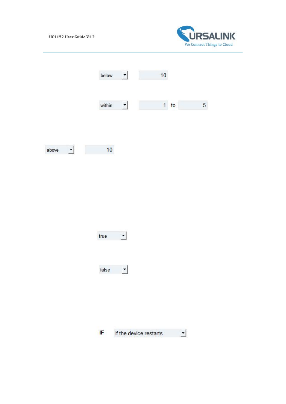
Then the user can choose from the following options (Type: Holding Register, Input Register):
• above
• below
• within
Thus, if the user chooses , then as soon as the value of this
Page 26
26
channel input goes above the specified threshold, the statement will be triggered.
Thus, if the user chooses , then as soon as the value of this
channel input goes below the specified threshold, the statement will be triggered.
Thus, if the user chooses , then as soon
as the value of this channel input goes within the specified threshold, the statement will be
triggered.
If you select a "Lockout Time" of 10s, a "Continue Time" of 5s, and choose
, the statement will be triggered as soon as the value of the
selected channel input goes above 10, and remains above 10 for 5s. It will then start checking the
value of the selected channel input again after 10s and be triggered once more if the value of the
selected analog input is above 10 for 5s.
If the "Lockout Time" is 0, the statement will only be triggered once (will be triggered again when
the trigger condition has changed and becomes true again).
Then the user can choose from the following options (Type: Coil, Discrete).
• True
• False
Thus, if the user chooses , then as soon as the value of this channel input is 1, the
statement will be triggered.
Thus, if the user chooses , then as soon as the value of this channel input is 0,
the statement will be triggered.
4.7.1.5 IF the Device Restarts
A command containing this IF condition will be triggered once the device has finished restarting.
Page 27
27
4.7.2 Supported THEN Actions
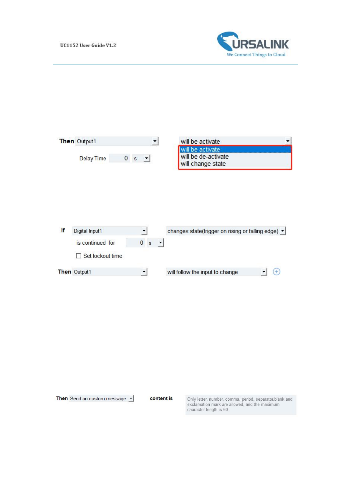
4.7.2.1 THEN Change Output
A command containing this Action will change the selected output according to specified actions.
The user can choose from the following actions:
• Will be activated
• Will be deactivated
• Will follow the input: When the triggering condition is the Input changes state, you can then
select change state as the action.
If the user has configured:
➢ "Delay Time", the selected output will be activated after the specified time.
➢ "Duration", the output will remain current status for a certain period of time.
4.7.2.2 THEN Send A Custom Message
A command containing this action will send a custom text message via LoRaWAN if the condition
is met. Only letter, number, comma, period, separator, space and exclamation mark are allowed
in the message, and the maximum character length is 60.
Page 28
28
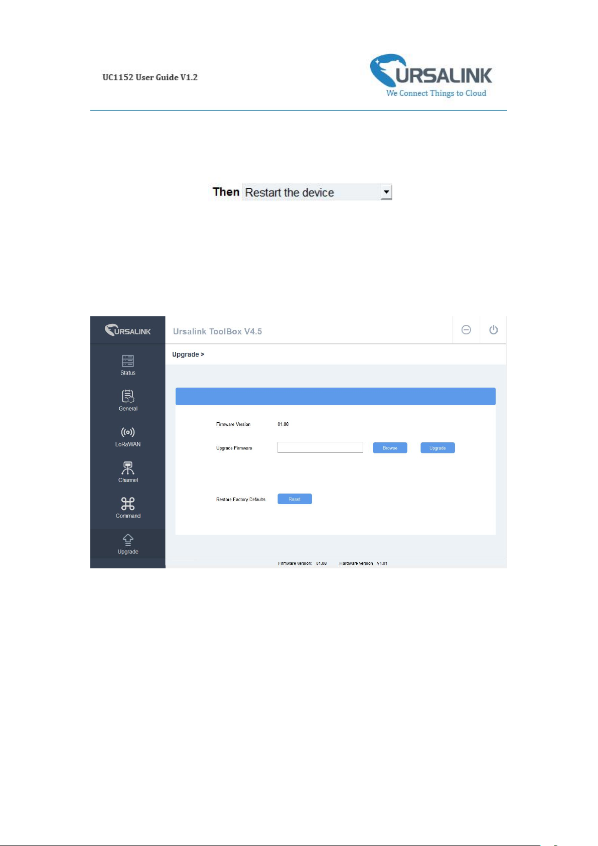
4.7.2.3 THEN Restart the Device
A command containing this Action will restart the Ursalink UC1152 if the condition is met.
4.8 Upgrade
Step 1: Connect UC1152 to PC via USB port.
Step 2: Power on UC1152.
Step 3: Run the Ursalink ToolBox and go to "Upgrade".
Step 4: Click "Browse" and select the correct firmware file from the PC.
Step 5: Click "Upgrade" and the device will check if the firmware file is correct. If it's correct, the
firmware will be imported to the device, and the device will restart after upgrading is completed.
Note: Any operation on Ursalink ToolBox is not allowed during upgrading, otherwise the
upgrading will be interrupted, or even the device will break down.
Click "Reset", and the device will restore to the factory default settings.
Page 29
29
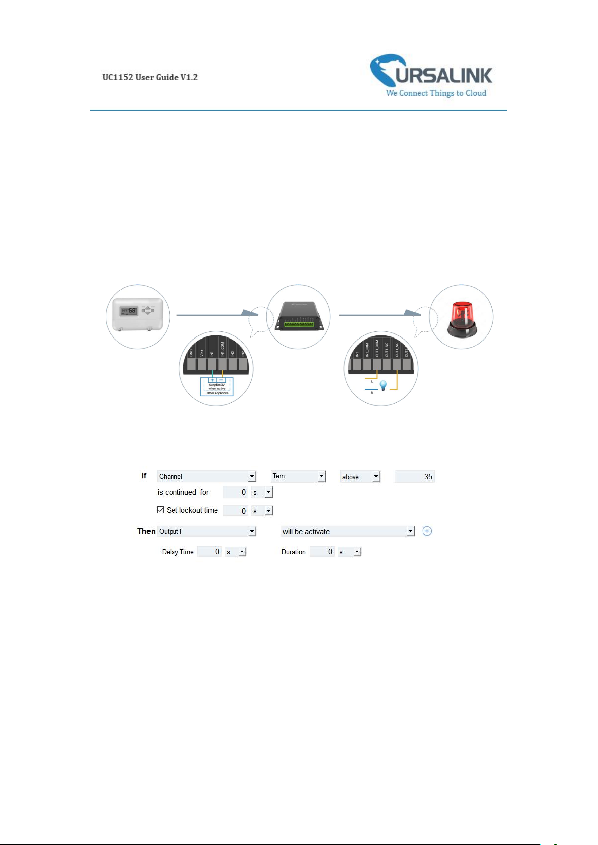
5. Application Examples
5.1 Send an Alert When Channel Value Exceeds a
Certain Threshold
Configuration:
Hardware:
Software:
-END-
 Loading...