

Page 1

UG67 Gateway
User Guide
Milesight IoT
Page 2
2
Preface
Document
Description
UG67 Datasheet
Datasheet for UG67 LoRaWAN®gateway.
UG67 Quick Start Guide
Quick Installation Guide for UG67 LoRaWAN®gateway.
Thanks for choosing Milesight UG67 LoRaWAN®gateway. UG67 delivers tenacious
connection over network with full-featured design such as automated failover/failback,
extended operating temperature, dual SIM cards, hardware watchdog, VPN, Gigabit
Ethernet and beyond.
This guide shows you how to configure and operate the UG67 LoRaWAN®gateway. You
can refer to it for detailed functionality and gateway configuration.
Readers
This guide is mainly intended for the following users:
- Network Planners
- On-site technical support and maintenance personnel
- Network administrators responsible for network configuration and maintenance
© Xiamen Milesight IoT Co., Ltd.
All rights reserved.
All information in this user guide is protected by copyright law. Whereby, no organization or
individual shall copy or reproduce the whole or part of this user guide by any means
without written authorization from Xiamen Milesight Iot Co., Ltd.
Related Documents
Declaration of Conformity
UG67 is in conformity with the essential requirements and other relevant provisions of the
CE, FCC, and RoHS.
Page 3

3
Revision History
Date
Doc Version
Description
Dec. 31, 2020
V1.0
Initial version
For assistance, please contact
Milesight technical support:
Email: [email protected]
Tel: 86-592-5085280
Fax: 86-592-5023065
Page 4

4
Contents
Chapter 1 Product Introduction
1.1 Overview
1.2 Advantages
1.3 Specifications
1.4 Dimensions (mm)
Chapter 2 Access to Web GUI
2.1 Wireless Access
2.2 Wired Access
Chapter 3 Web Configuration
3.1 Status
3.1.1 Overview
3.1.2 Packet Forwarder
3.1.3 Cellular
3.1.4 Network
3.1.5 WLAN
3.1.6 VPN
3.1.7 Host List
3.2 LoRaWAN
3.2.1 Packet Forwarder
3.2.2 Network Server
3.3 Network
3.3.1 Interface
3.3.2 Firewall
.................................................................................................................................
............................................................................................................................
.......................................................................................................................
...............................................................................................................
.................................................................................................................
......................................................................................................................
.........................................................................................................
...................................................................................................................................
...................................................................................................................
.....................................................................................................................
....................................................................................................................
........................................................................................................................
...........................................................................................................................
...................................................................................................................
.............................................................................................................................
3.2.1.1 General
3.2.1.2 Radios
3.2.1.3 Advanced
3.2.1.4 Custom
3.2.1.5 Traffic
3.2.2.1 General
3.2.2.2 Application
3.2.2.3 Profiles
3.2.2.4 Device
3.2.2.5 Gateway
3.2.2.6 Packets
................................................................................................................................
3.3.1.1 Port
3.3.1.2 WLAN
3.3.1.3 Cellular
3.3.1.4 Loopback
.....................................................................................................................
3.3.2.1 Security
3.3.2.2 ACL
3.3.2.3 DMZ
..........................................................................................................
...........................................................................................................
..........................................................................................................
............................................................................................................
..........................................................................................................
..........................................................................................................
............................................................................................................
.........................................................................................................
...................................................................................................................
................................................................................................................
.............................................................................................................
..........................................................................................................
................................................................................................................
...............................................................................................................
........................................................................................................
.........................................................................................................
...................................................................................................
...................................................................................................
......................................................................................................
.......................................................................................................
...................................................................................................
........................................................................................................
......................................................................................................
.........................................................................................................
7
7
7
8
10
11
11
12
15
15
15
16
17
19
19
20
21
22
23
23
24
26
27
27
29
29
31
34
37
40
41
44
44
44
47
50
53
53
54
54
56
Page 5

5
3.3.2.4 Port Mapping
3.3.2.5 MAC Binding
3.3.3 DHCP
3.3.4 DDNS
.........................................................................................................................
.........................................................................................................................
3.3.5 Link Failover
3.3.5.1 SLA
3.3.5.2 Track
3.3.5.3 WAN Failover
3.3.6 VPN
...........................................................................................................................
3.3.6.1 DMVPN
3.3.6.2 IPSec
3.3.6.3 GRE
3.3.6.4 L2TP
3.3.6.5 PPTP
3.3.6.6 OpenVPN Client
3.3.6.7 OpenVPN Server
3.3.6.8 Certifications
3.4 System
.................................................................................................................................
3.4.1 General Settings
3.4.1.1 General
3.4.1.2 System Time
3.4.1.3 SMTP
3.4.1.4 Phone
3.4.1.5 Email
3.4.2 User Management
3.4.2.1 Account
3.4.2.2 User Management
3.4.3 SNMP
........................................................................................................................
3.4.3.1 SNMP
3.4.3.2 MIB View
3.4.3.3 VACM
3.4.3.4 Trap
3.4.3.5 MIB
3.4.5 Device Management
3.4.6 Events
.......................................................................................................................
3.4.6.1 Events
3.4.6.2 Events Settings
3.5 Maintenance
3.5.1 Tools
.......................................................................................................................
.........................................................................................................................
3.5.1.1 Ping
3.5.1.2 Traceroute
3.5.2 Schedule
3.5.3 Log
...................................................................................................................
.............................................................................................................................
3.5.3.1 System Log
...............................................................................................
................................................................................................
............................................................................................................
................................................................................................................
.............................................................................................................
...............................................................................................
..........................................................................................................
.............................................................................................................
................................................................................................................
..............................................................................................................
.............................................................................................................
...........................................................................................
.........................................................................................
...............................................................................................
.....................................................................................................
..........................................................................................................
................................................................................................
.............................................................................................................
............................................................................................................
..............................................................................................................
..................................................................................................
.........................................................................................................
......................................................................................
............................................................................................................
.......................................................................................................
............................................................................................................
...............................................................................................................
.................................................................................................................
..............................................................................................
............................................................................................................
...........................................................................................
................................................................................................................
....................................................................................................
..................................................................................................
56
57
58
59
60
60
61
62
63
63
64
67
68
70
72
73
75
77
77
77
78
80
80
81
82
82
83
83
84
84
85
86
86
87
88
88
89
90
90
90
90
91
91
91
Page 6

6
3.5.3.2 Log Settings
3.5.4 Upgrade
....................................................................................................................
3.5.5 Backup and Restore
3.5.6 Reboot
3.6 APP
3.6.1 Python
.......................................................................................................................................
3.6.1.1 Python
......................................................................................................................
.......................................................................................................................
...........................................................................................................
3.6.1.2 App Manager Configuration
3.6.1.3 Python App
Chapter 4 Application Examples
4.1 Packet Forwarder Configuration
4.2 Application Configuration
4.3 Device Configuration
4.4 Send Data to Device
.......................................................................................................
........................................................................................................
4.5 Restore Factory Defaults
4.5.1 Via Web Interface
4.5.2 Via Hardware
4.6 Firmware Upgrade
4.7 Cellular Connection
.........................................................................................................
...........................................................................................................
.........................................................................................................
4.8 Wi-Fi Application Example
4.8.1 AP Mode
4.8.2 Client Mode
................................................................................................................
...........................................................................................................
.................................................................................................
...............................................................................................
......................................................................
...................................................................................................
....................................................................................................
.....................................................................................
................................................................................................
................................................................................................
.................................................................................................
.............................................................................................
92
93
94
94
95
95
96
96
97
98
98
99
101
102
105
105
107
107
108
109
109
110
Page 7
7
Chapter 1 Product Introduction
1.1 Overview
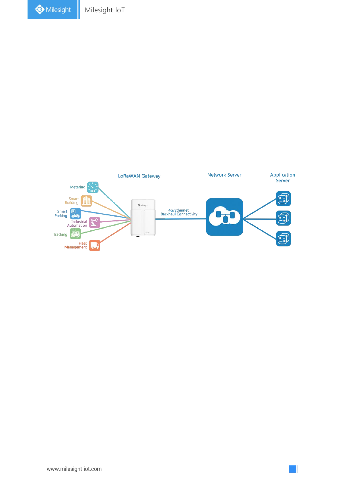
UG67 is a robust 8-channel indoor LoRaWAN®gateway. Adopting SX1302 LoRa chip and
high-performance quad-core CPU, UG67 supports connection with more than 2000 nodes.
UG67 has line of sight up to 10km and can cover about 2km in urbanized environment,
which is ideally suited to smart office, smart building and many other indoor applications.
UG67 supports not only multiple back-haul backups with Ethernet, Wi-Fi and cellular, but
also has integrated mainstream network servers (such as TTN, ChirpStack, etc.) and
built-in network server and Milesight IoT Cloud for easy deployment.
Figure 1-1
1.2 Advantages
Benefits
- Built-in industrial CPU and big memory;
- Ethernet, 2.4GHz Wi-Fi and global 2G/3G/LTE options make it easy to get connected
Embedded network server and compliant with several third party network servers
-
- MQTT, HTTP or HTTPS protocol for data transmission to application server
Rugged enclosure, optimized for wall or pole mounting
-
- 3-year warranty included
Security & Reliability
- Automated failover/failback between Ethernet and Cellular (dual SIM)
Enable unit with security frameworks like IPsec/OpenVPN/GRE/L2TP/PPTP/ DMVPN
-
- Embedded hardware watchdog to automatically recover from various failure and
ensure highest level of availability
Page 8

8
Easy Maintenance
Hardware System
CPU
Quad-core 1.5GHz, 64-bit ARM Cortex-A53
Memory
8 GB eMMC Flash, 512 MB DDR4 RAM
LoRaWAN
Antenna
2 × Internal Antennas +
2 × 50 Ω N-Female External Connectors
Channel
8
Frequency Band
CN470/IN865/EU868/RU864/US915/AU915/KR920/AS923
Sensitivity
-140dBm Sensitivity @292bps
Output Power
27dBm Max
Protocol
V1.0 Class A/Class C and V1.0.2 Class A/Class C
Ethernet
Ports
1 × RJ-45 (PoE PD supported)
Physical Layer
10/100/1000 Base-T (IEEE 802.3)
Data Rate
10/100/1000 Mbps (auto-sensing)
- Milesight DeviceHub provides easy setup, mass configuration, and centralized
management of remote devices
- The user-friendly web interface design and various upgrading options help
administrator to manage the device as easy as pie
- WEB GUI and CLI enable the admin to achieve quick configuration and simple
management among a large quantity of devices
- Users can efficiently manage the remote devices on the existing platform through the
industrial standard SNMP
Capabilities
- Link remote devices in an environment where communication technologies are
constantly changing
- Industrial quad core 64-bit ARM Cortex-A53 processor, high-performance operating up
to 1.5GHz with low power consumption, and 8GB eMMC available to support more
applications
- Support wide operating temperature ranging from -40°C to 70°C/-40°F to 158°F
1.3 Specifications
Page 9

9
Physical Characteristics
Ingress Protection
IP67
Dimensions
250 x 172 x 92 mm
Interface
Auto MDI/MDIX
Mode
Full or half duplex (auto-sensing)
Wi-Fi Interfaces
Antenna
Fully Integrated and Internal Antenna
Standards
IEEE 802.11 b/g/n
Tx Power
802.11b: 18 dBm +/-2.0 dBm (11 Mbps)
802.11g: 15 dBm +/-2.0 dBm (6 Mbps)
802.11g: 15 dBm +/-2.0 dBm (54 Mbps)
[email protected] GHz: 14 dBm +/-2.0 dBm (MCS0_HT20)
[email protected] GHz: 14 dBm +/-2.0 dBm (MCS7_HT20)
[email protected] GHz: 13 dBm +/-2.0 dBm (MCS0_HT40)
[email protected] GHz: 13 dBm +/-2.0 dBm (MCS7_HT40)
Cellular Interfaces (Optional)
Antenna
Internal Antenna
SIM Slots
1
GPS
Antenna
Internal Antenna
Sensitivity
-167dBm@Tracking, -149dBm@Acquisition,
-161dBm@Re-acquisition
Position Accuracy
<2.5m CEP
Software
Network Protocols
PPPoE, SNMP v1/v2c/v3, TCP, UDP, DHCP, DDNS, HTTP,
HTTPS, DNS, SNTP, Telnet, SSH, MQTT, etc.
VPN Tunnel
DMVPN/IPsec/OpenVPN/PPTP/L2TP/GRE
Access Authentication
CHAP/PAP/MS-CHAP/MS-CHAPV2
Firewall
ACL/DMZ/Port Mapping/MAC Binding
Management
Web, CLI, SMS, On-demand dial up
Power Supply and Consumption
Power Supply
1. 1 × 802.3 af PoE Input
2. 12 VDC with M12 Connector
Consumption
Typical 3.6W, Max 4.8W
Page 10
10
Mounting
Wall or Pole Mounting
Others
Reset Button
1 × RST
LED Indicators
1 × SYS, 1 × LoRa, 1 × LTE
Built-in
Watchdog, RTC, Timer
Environmental
Operating
Temperature
-40°C to +70°C (-40°F to +158°F)
Reduced cellular performance above 60°C
Storage Temperature
-40°C to +85°C (-40°F to +185°F)
Ethernet Isolation
1.5 kV RMS
Relative Humidity
0% to 95% (non-condensing) at 25°C/77°F
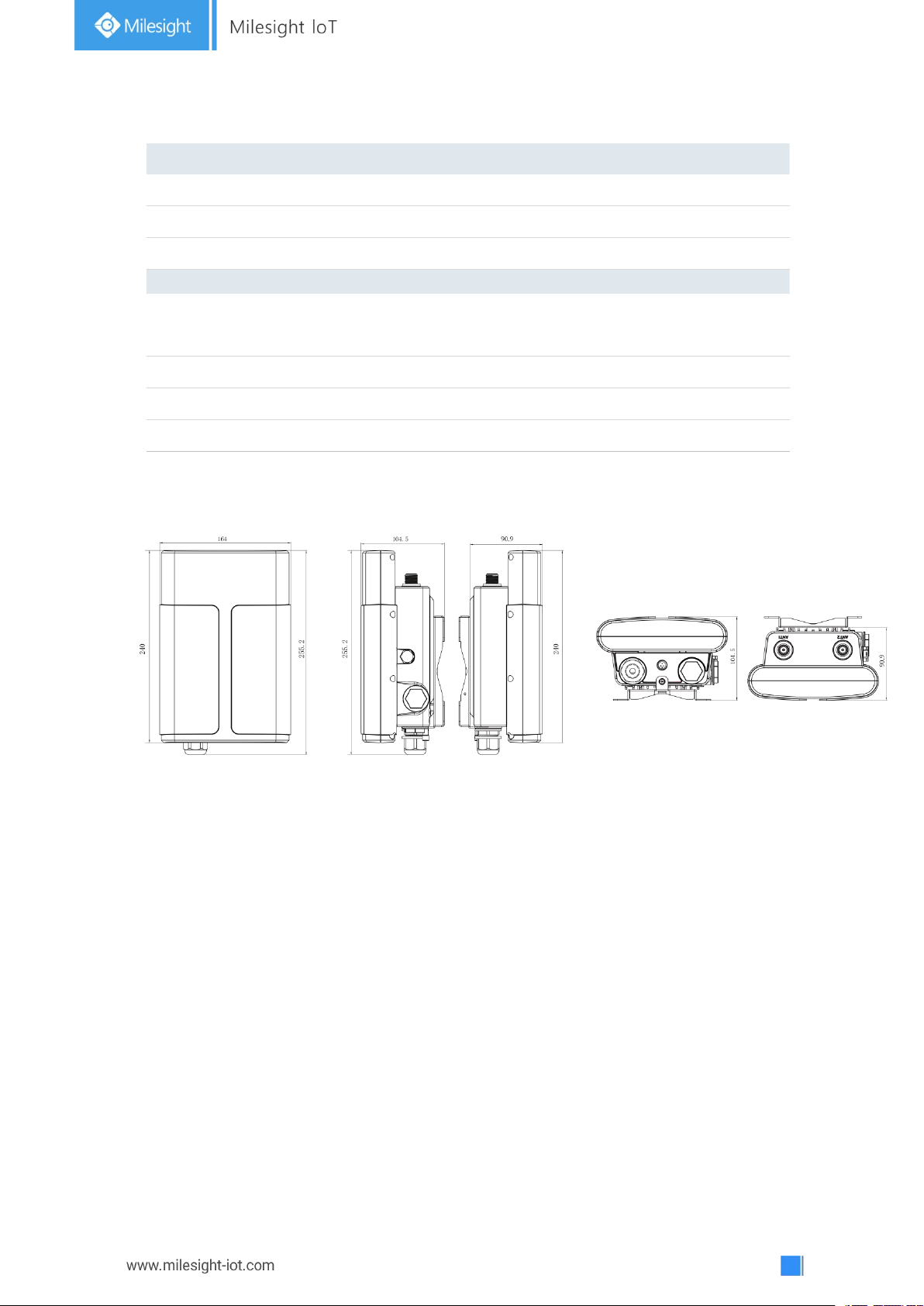
1.4 Dimensions (mm)
Page 11
11
Chapter 2 Access to Web GUI
If you enter the username or password incorrectly more than 5 times, the login page
will be locked for 10 minutes.
This chapter explains how to access to Web GUI of the UG67.
2.1 Wireless Access
1. Enable Wireless Network Connection on your computer and search for access point
“Gateway_******” to connect it.
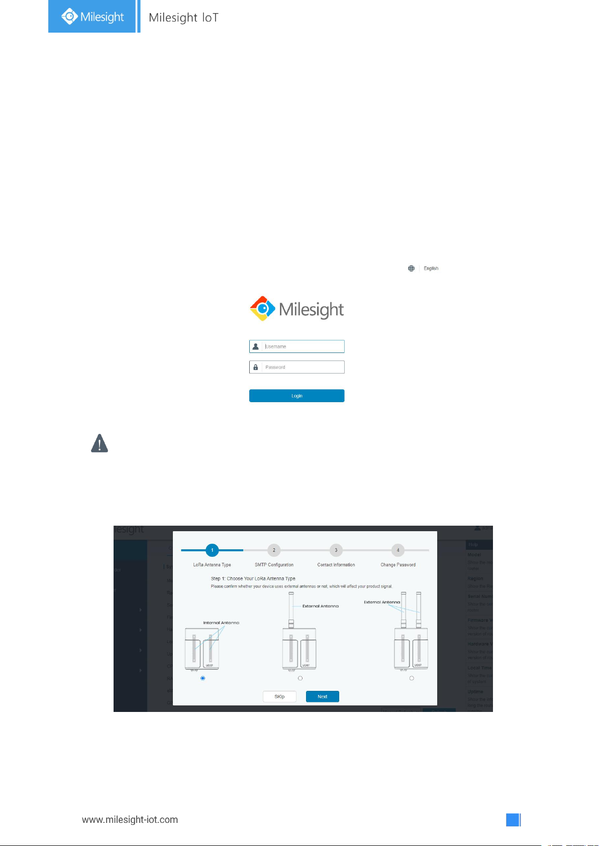
2. Open a Web browser on your PC (Chrome is recommended) and type in the IP address
192.168.1.1 to access the web GUI.
3. Enter the username and password, click “Login”.
4. After logging the web GUI, follow the guide to complete the basic configurations. You
can also skip the instructions. It’s suggested that you change the password for the sake of
security.
5. You can view system information and perform configuration of the gateway.
Page 12
12
2.2 Wired Access
Connect PC to UG67 ETH port directly or through PoE injector to access the web GUI of
gateway. The following steps are based on Windows 10 system for your reference.
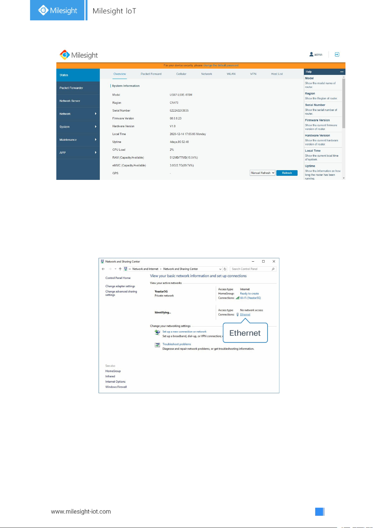
1. Go to “Control Panel” → “Network and Internet” → “Network and Sharing Center”, then
click “Ethernet” (May have different names).
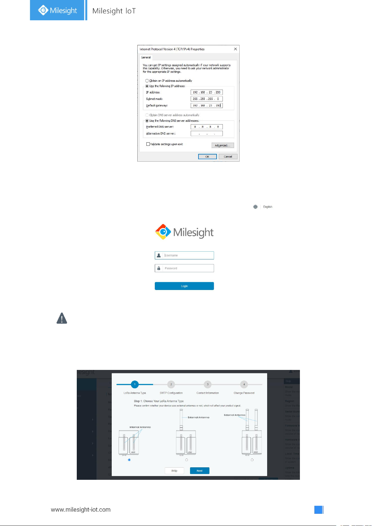
2. Go to “Properties” → “Internet Protocol Version 4(TCP/IPv4) ”and select “Use the
following IP address”, then assign a static IP manually within the same subnet of the
gateway.
Page 13
13
3. Open a Web browser on your PC (Chrome is recommended) and type in the IP address
If you enter the username or password incorrectly more than 5 times, the login page
will be locked for 10 minutes.
192.168.23.150 to access the web GUI.
4. Enter the username and password, click “Login”.
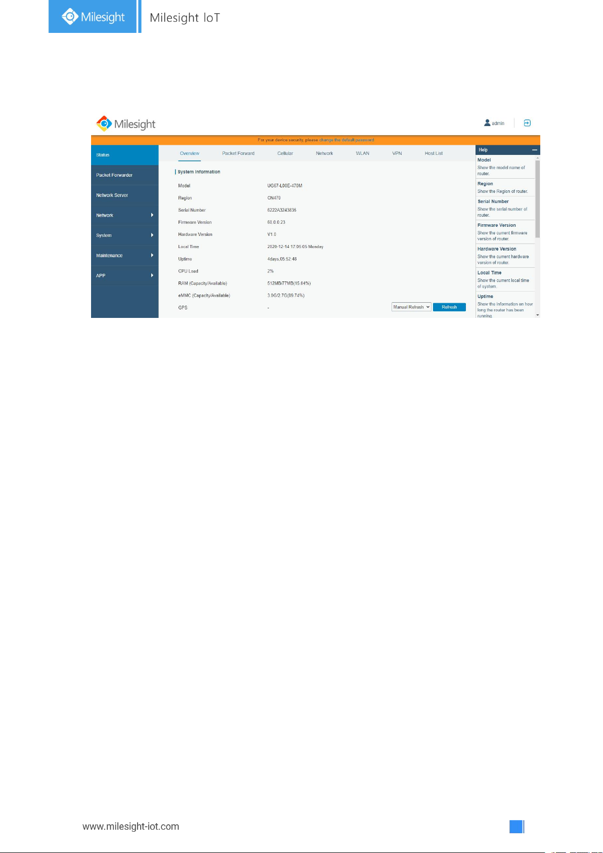
5. After logging the web GUI, follow the guide to complete the basic configurations. You
can also skip the instructions. It’s suggested that you change the password for the sake of
security.
Page 14
14
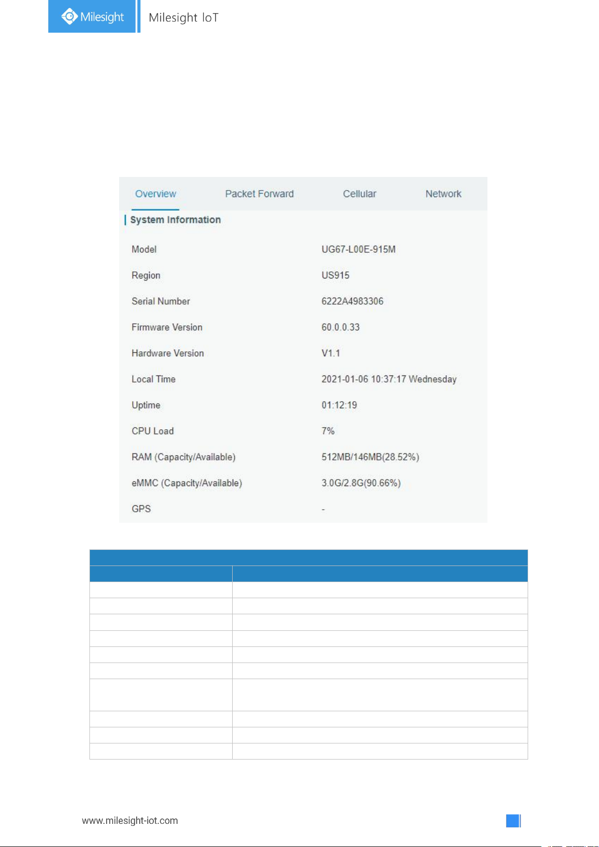
6. After guide complete, you can view system information and perform configuration of
the gateway.
Page 15
15
Chapter 3 Web Configuration
System Information
Item
Description
Model
Show the model name of gateway.
Region
Show the LoRaWAN®frequency region of gateway.
Serial Number
Show the serial number of gateway.
Firmware Version
Show the currently firmware version of gateway.
Hardware Version
Show the currently hardware version of gateway.
Local Time
Show the currently local time of system.
Uptime
Show the information on how long the gateway has been
running.
CPU Load
Show the current CPU utilization of the gateway.
RAM (Capacity/Available)
Show the RAM capacity and the available RAM memory.
eMMC (Capacity/Available)
Show the eMMC capacity and the available eMMC memory.
3.1 Status
3.1.1 Overview
You can view the system information of the gateway on this page.
Figure 3-1-1-1
Page 16
16
GPS
Show GPS data of the gateway.
Table 3-1-1-1 System Information
Packet Forwarder Status
Item
Description
Basic
Version
Show the version of packet forwarder software.
Status
Show the status of packet forwarder.
Gateway ID
Show the ID of the gateway.
Region Code
Show the LoRa region code which is based on the
gateway’s variant.
Uplink
Packet Received
Show the count of data packet from node to gateway.
Packets received State
Show the RF packets receiving state:
CRC_OK: Percentage of CRC verification
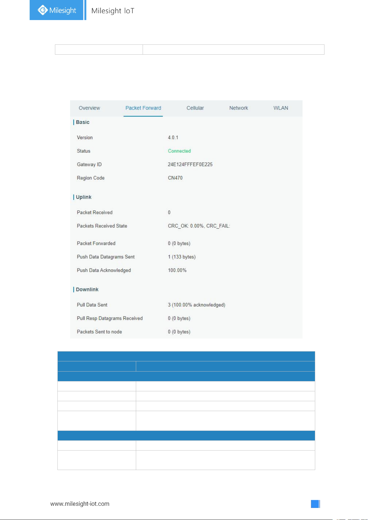
3.1.2 Packet Forwarder
You can view the packet forward status of gateway on this page.
Figure 3-1-2-1
Page 17
17
CRC_Fail: Percentage of CRC verification failure
NO_CRC: Percentage of abnormal packets without CRC
Packets Forwarded
Packets that CRC verified are sent from gateway to server.
Push Data Datagrams
Sent
The total quantity of packets sent from gateway to server,
including the RF packets forwarded and statistics packets.
Push Data
Acknowledged
Percentage of acknowledged packets among Push Data
Datagrams Sent.
Downlink
Pull Data Sent
Show the number of keepalive packets sent to the server,
and percentage of acknowledged packet regarding the
keepalive packet from the server.
Pull Resp Datagrams
Received
Show the packet counts and size that will be sent from
server to gateway.
Packets Sent to node
Show the RF packet counts and size that will be sent from
gateway to node.
Packets Sent Errors
Show the RF packet counts that fail to be sent from server
to node.
Table 3-1-2-1 LoRaWAN Status
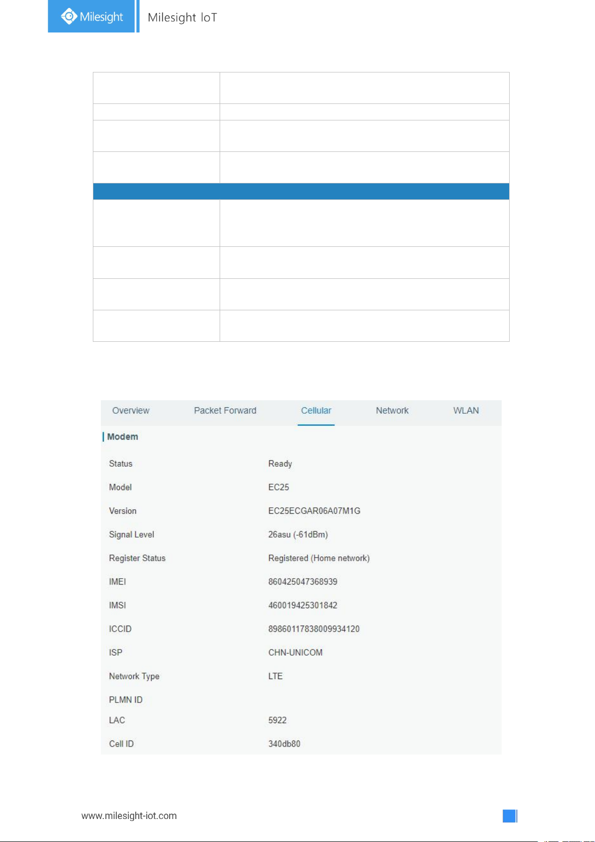
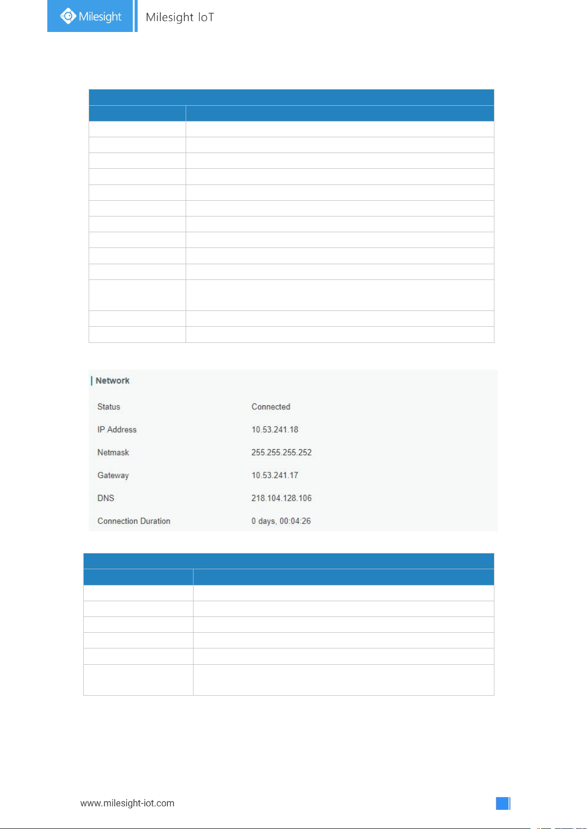
3.1.3 Cellular
You can view the cellular network status of gateway on this page.
Page 18
18
Figure 3-1-3-1
Modem Information
Item
Description
Status
Show corresponding detection status of module and SIM card.
Model
Show the model name of cellular module.
Version
Show the version of cellular module.
Signal Level
Show the cellular signal level.
Register Status
Show the registration status of SIM card.
IMEI
Show the IMEI of the module.
IMSI
Show IMSI of the SIM card.
ICCID
Show ICCID of the SIM card.
ISP
Show the network provider which the SIM card registers on.
Network Type
Show the connected network type, such as LTE, 3G, etc.
PLMN ID
Show the current PLMN ID, including MCC, MNC, LAC and Cell
ID.
LAC
Show the location area code of the SIM card.
Cell ID
Show the Cell ID of the SIM card location.
Network Status
Item
Description
Status
Show the connection status of cellular network.
IP Address
Show the IP address of cellular network.
Netmask
Show the netmask of cellular network.
Gateway
Show the gateway of cellular network.
DNS
Show the DNS of cellular network.
Connection Duration
Show information on how long the cellular network has been
connected.
Table 3-1-3-1 Modem Information
Figure 3-1-3-2
Table 3-1-3-2 Network Status
Page 19
19
3.1.4 Network
Network
Item
Description
Port
Show the name of the Ethernet port.
Status
Show the status of the Ethernet port. "Up" refers to a status that WAN
is enabled and Ethernet cable is connected. "Down" means Ethernet
cable is disconnected or WAN function is disabled.
Type
Show the dial-up type of the Ethernet port.
IP Address
Show the IP address of the Ethernet port.
Netmask
Show the netmask of the Ethernet port.
Gateway
Show the gateway of the Ethernet port.
DNS
Show the DNS of the Ethernet port.
Duration
Show the information about how long the Ethernet cable has been
connected to the Ethernet port when the port is enabled. Once the port
is disabled or Ethernet cable is disconnected, the duration will stop.
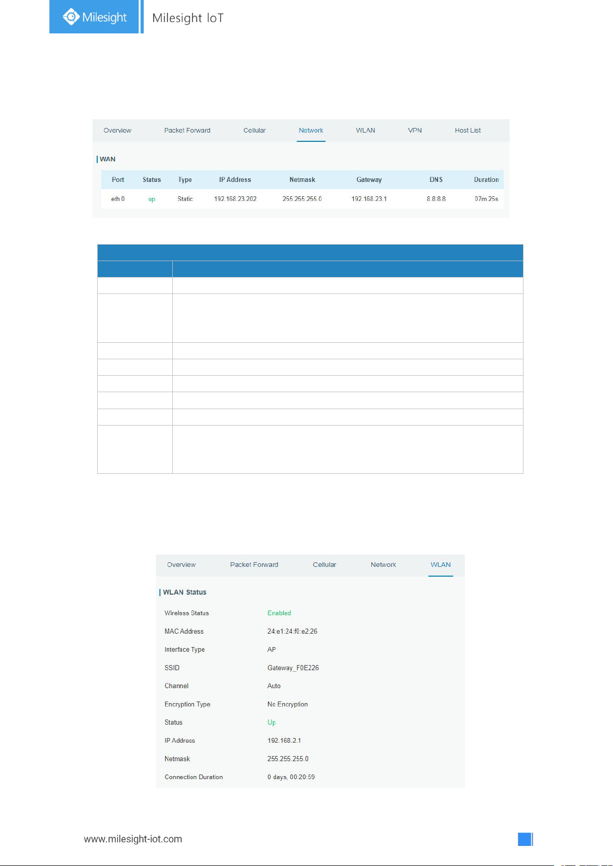
On this page you can check the Ethernet port status of the gateway.
Figure 3-1-4-1
Table 3-1-4-1 WAN Status
3.1.5 WLAN
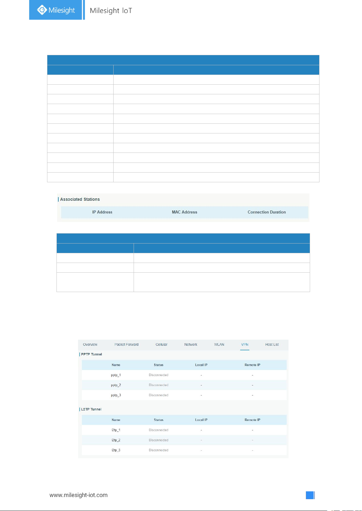
You can check Wi-Fi status on this page, including the information of access point and
client.
Page 20
20
Figure 3-1-5-1
WLAN Status
Item
Description
Wireless Status
Show the wireless status.
MAC Address
Show the MAC address.
Interface Type
Show the interface type, such as "AP" or “Client".
SSID
Show the SSID.
Channel
Show the wireless channel.
Encryption Type
Show the encryption type.
Status
Show the connection status.
IP Address
Show the IP address of the gateway.
Netmask
Show the wireless MAC address of the gateway.
Gateway
Show the gateway address in wireless network.
Connection Duration
Show information on how long the Wi-Fi network has been connected.
Associated Stations
Item
Description
IP Address
Show the IP address of access point or client.
MAC Address
Show the MAC address of the access point or client.
Connection Duration
Show information on how long the Wi-Fi network has been
connected.
Table 3-1-5-1 WLAN Status
Figure 3-1-5-2
Table 3-1-5-2 WLAN Status
3.1.6 VPN
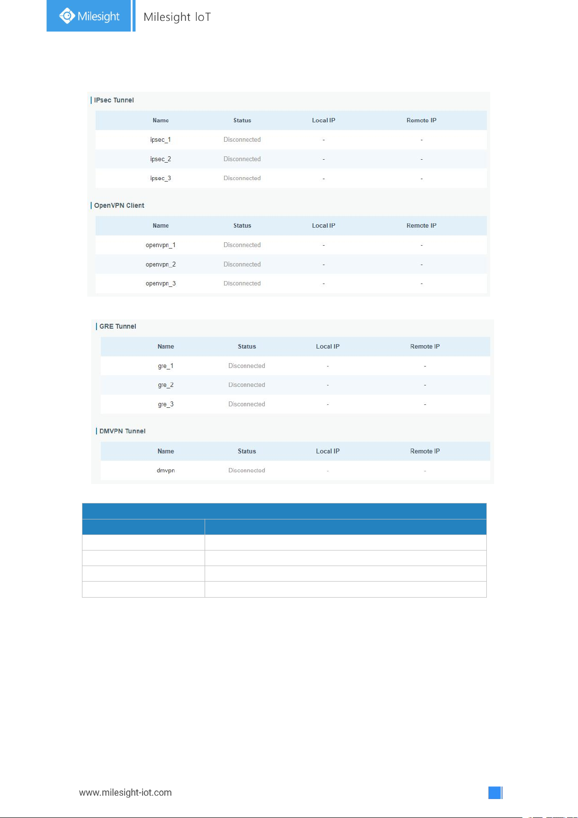
You can check VPN status on this page, including PPTP, L2TP, IPsec, OpenVPN and
DMVPN.
Page 21
21
Figure 3-1-6-1
VPN Status
Item
Description
Name
Show the name of the VPN tunnel.
Status
Show the status of the VPN tunnel.
Local IP
Show the local tunnel IP of VPN tunnel.
Remote IP
Show the remote tunnel IP of VPN tunnel.
Figure 3-1-6-2
Figure 3-1-6-3
Table 3-1-6-1 VPN Status
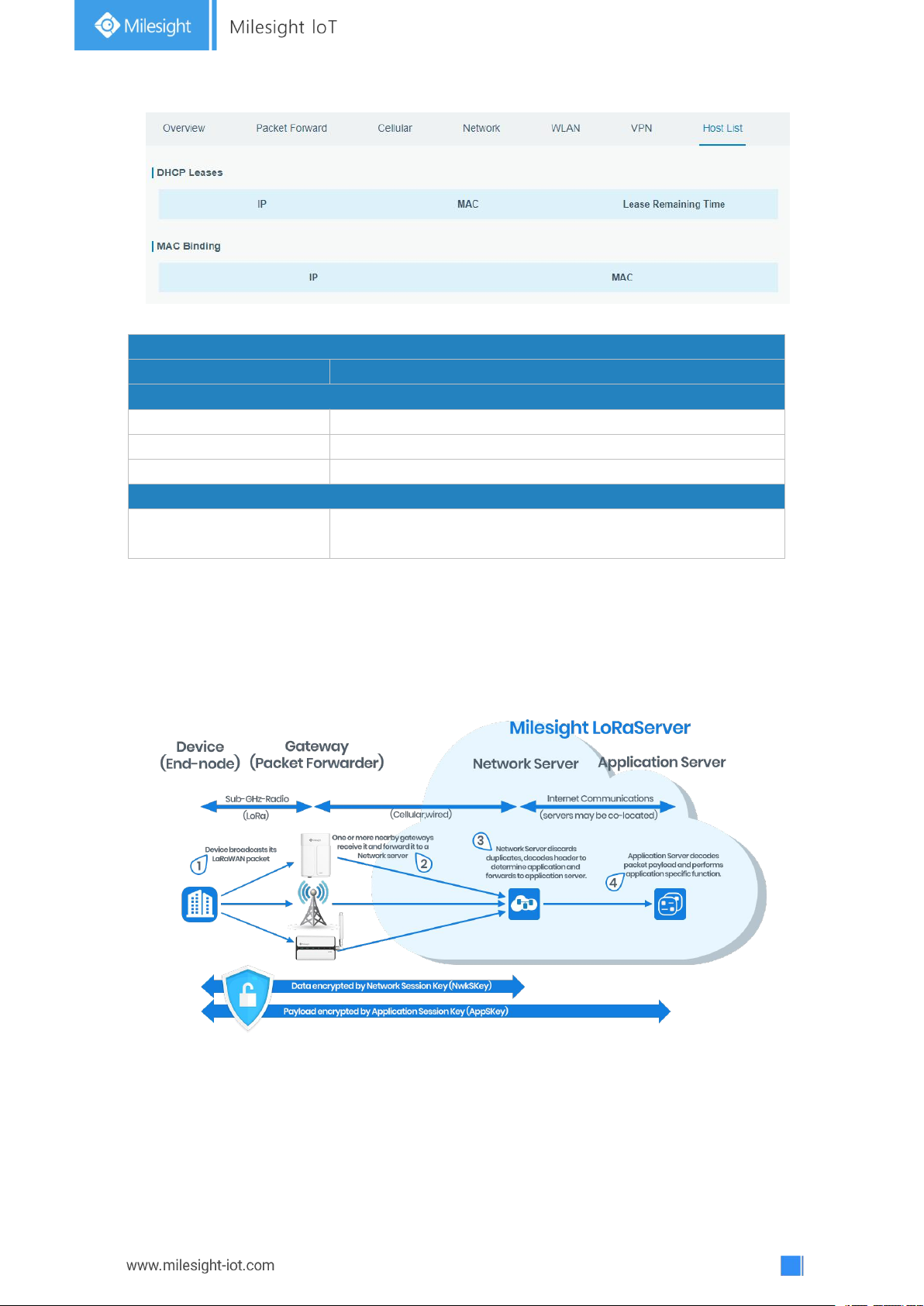
3.1.7 Host List
You can view the host information on this page.
Page 22
22
Host List
Item
Description
DHCP Leases
IP Address
Show IP address of DHCP client
MAC Address
Show MAC address of DHCP client
Lease Time Remaining
Show the remaining lease time of DHCP client.
MAC Binding
IP & MAC
Show the IP address and MAC address set in the Static IP
list of DHCP service.
3.2 LoRaWAN
Figure 3-1-7-1
Table 3-1-7-1 Host List Description
Page 23
23
3.2.1 Packet Forwarder
General Settings
Item
Description
Default
Gateway EUI
Show the identifier of the gateway.
Generated from MAC
address of the
gateway and cannot
be changed.
Gateway ID
Fill in the corresponding ID which you’ve used
for register gateway on the remote network
server, such as TTN. It is usually the same as
gateway EUI and can be changed.
The same as
gateway EUI.
Frequency-Sync
Sync frequency configurations from network
server by selecting the corresponding ID.
Disabled
Multi-Destination
The gateway will forward the data to the
network server address that was created and
enabled in the list.
Local host
3.2.1.1 General
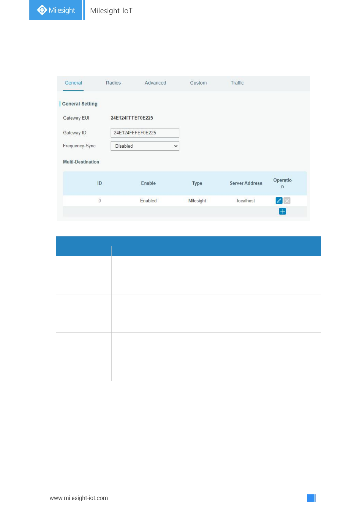
Figure 3-2-1-1
Table 3-2-1-1 General Setting Parameters
Related Configuration Example
Packet fowarder configuration
Page 24
24
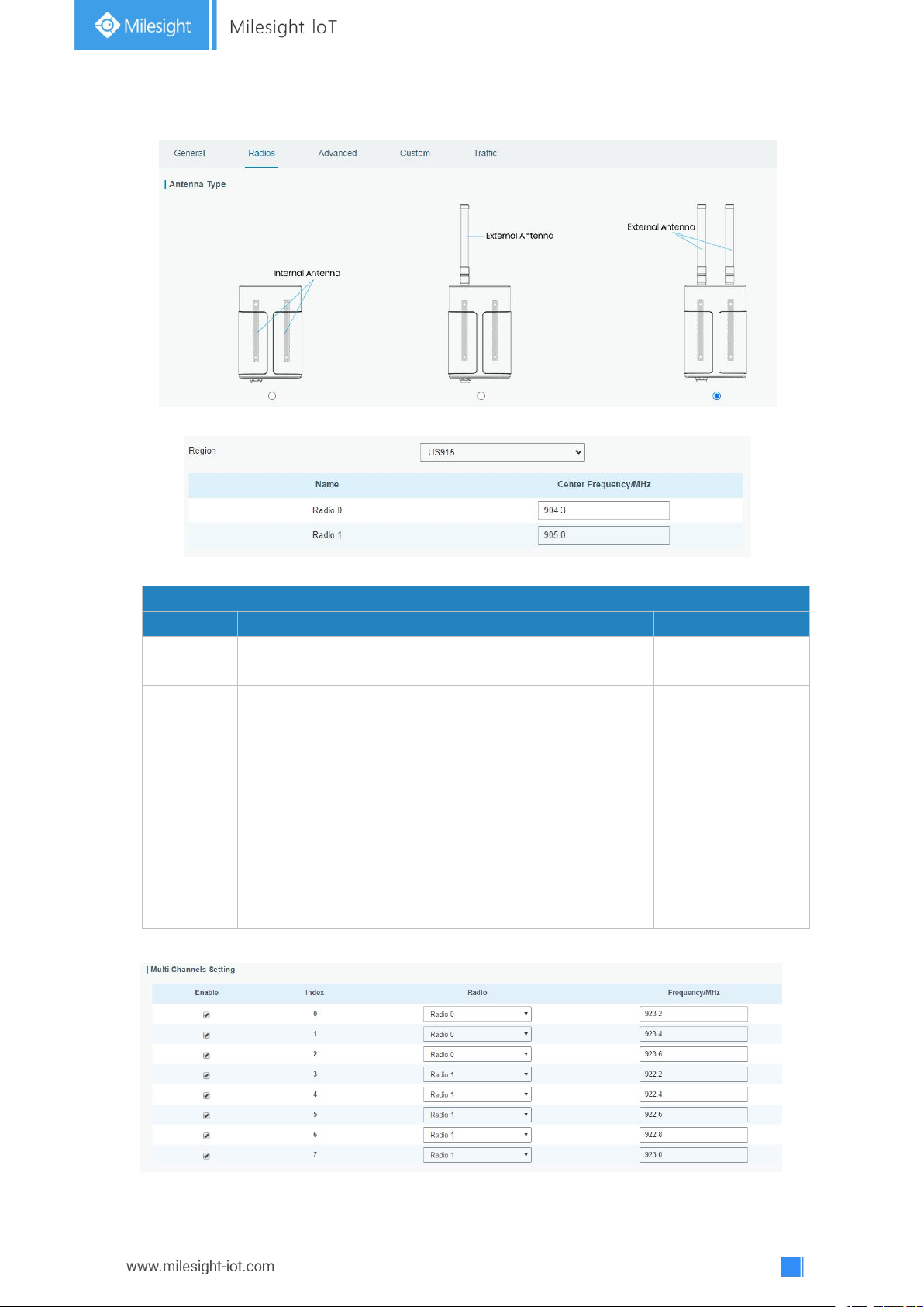
3.2.1.2 Radios
Radios-Radio Channel Setting
Item
Description
Default
Antenna
Type
Select the transmission type of antennas.
Internal Antenna
Region
Choose the LoRaWAN®frequency plan used for the
upstream and downlink frequencies and datarates.
Available channel plans depend on the gateway’s
model.
Based on the
gateway’s model
Center
Frequency
Radio 0 : supports transmitting and receiving packet.
Radio 1 : only supports receiving packet from nodes.
Based on what is
specified in the
LoRaWAN
®
regional
parameters
document
Figure 3-2-1-2
Figure 3-2-1-3
Table 3-2-1-2 Radio Channels Setting Parameters
Page 25
25
Figure 3-2-1-4
Radios-Multi Channel Setting
Item
Description
Default
Enable
Click to enable this channel to transmit
packets.
Enabled
Index
Indicate the ordinal of the list.
/
Radio
Choose Radio 0 or Radio 1 as center
frequency.
Radio 0
Frequency/MHz
Enter the frequency of this channel.
Range: center frequency±0.9.
Based on the
LoRaWAN
®
regional document
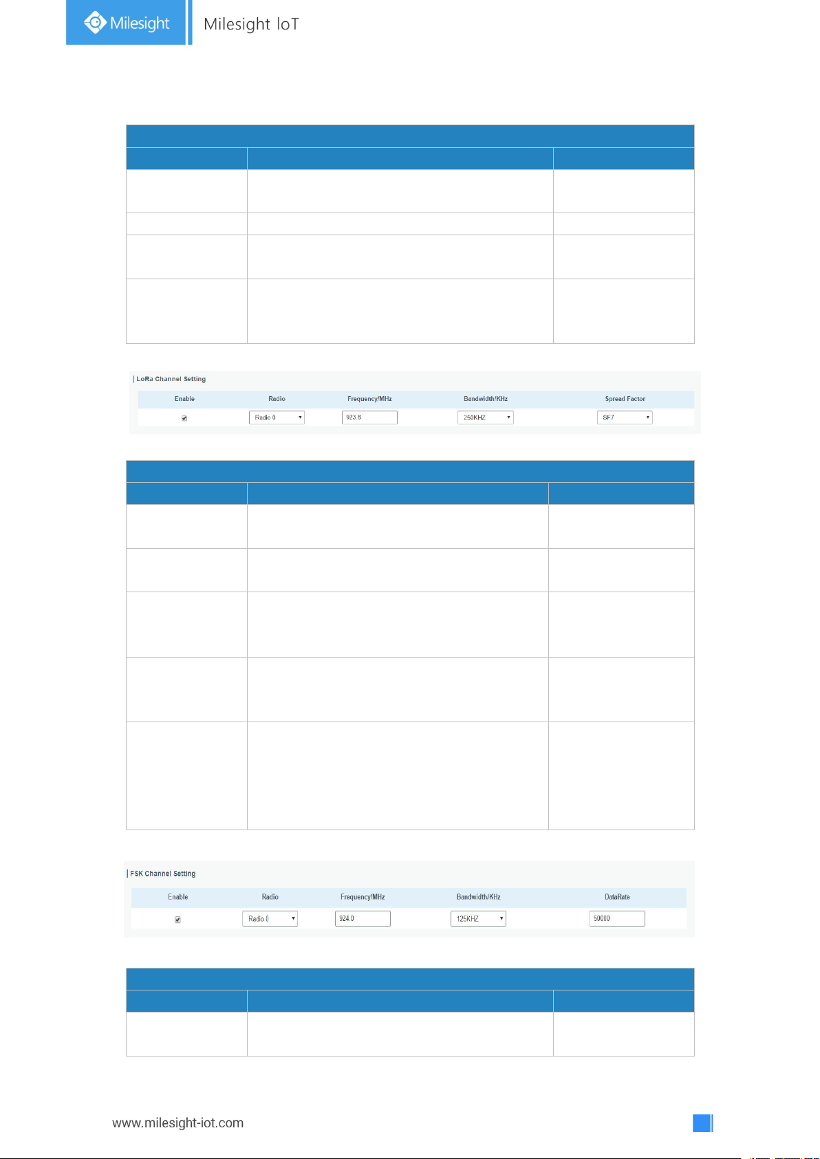
Radios-LoRa Channel Setting
Item
Description
Default
Enable
Click to enable this channel to transmit
packets.
Enabled
Radio
Choose Radio 0 or Radio 1 as center
frequency.
Radio 0
Frequency/MHz
Enter the frequency of this channel.
Range: center frequency±0.9.
Based on the
supported
frequency
Bandwidth/MHz
Enter the bandwidth of this channel.
Recommended value: 125KHz, 250KHz,
500KHz
500KHz
Spread Factor
Choose the selectable spreading factor. The
channel with large spreading factor
corresponds to a low rate, while the small
one corresponds to a high rate.
Based on what is
specified in the
LoRaWAN®regional
parameters
document
Radios-FSK Channel Setting
Item
Description
Default
Enable
Click to enable this channel to transmit
packets.
Disabled
Table 3-2-1-3 Multi Channel Setting Parameters
Figure 3-2-1-5
Table 3-2-1-4 LoRa Channel Setting Parameters
Figure 3-2-1-6
Page 26
26
Radio
Choose Radio 0 or Radio 1 as center
frequency.
Radio 0
Frequency/MHz
Enter the frequency of this channel.
Range: center frequency±0.9.
Based on the
supported
frequency
Bandwidth/MHz
Enter the bandwidth of this channel.
Recommended value: 125KHz, 250KHz,
500KHz
Based on the
supported
frequency
Data Rate
Enter the data rate. Range:500-25000.
500
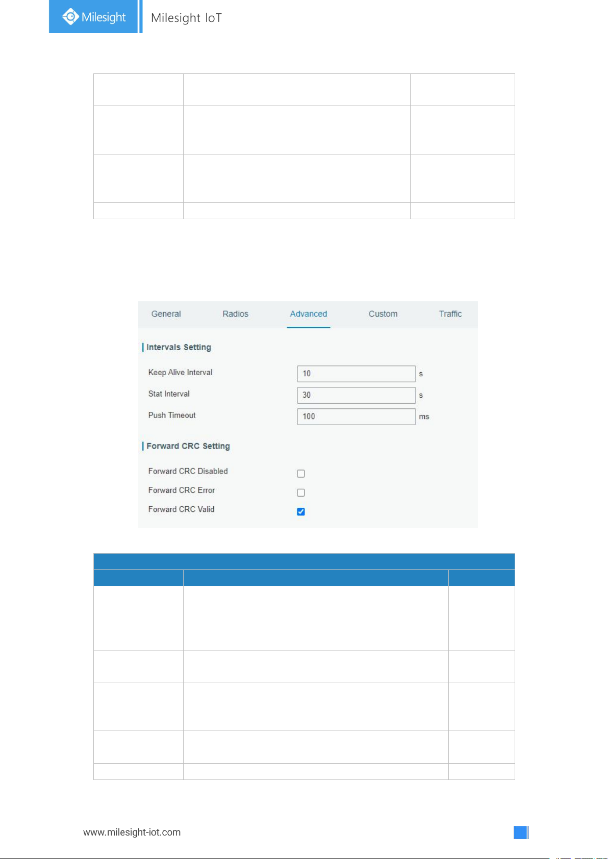
3.2.1.3 Advanced
Advanced
Item
Description
Default
Keep Alive
Interval
Enter the interval of keepalive packet which is sent
from gateway to network server to keep the
connection stable and alive.
Range: 1-3600.
10
Stat Interval
Enter the interval to update the network server with
gateway statistics. Range: 1-3600.
30
Push Timeout
Enter the timeout to wait for the response from
server after the gateway sends data of node. Rang:
1-1999.
100
Forward CRC
Disabled
Enable to send packets received with CRC disabled to
the network server.
Disabled
Forward CRC
Enable to send packets received with CRC errors to
Disabled
Table 3-2-1-5 FSK Channel Setting Parameters
Figure 3-2-1-7
Page 27
27
Error
the network server.
Forward CRC
Valid
Enable to send packets received with CRC valid to the
network server.
Enabled
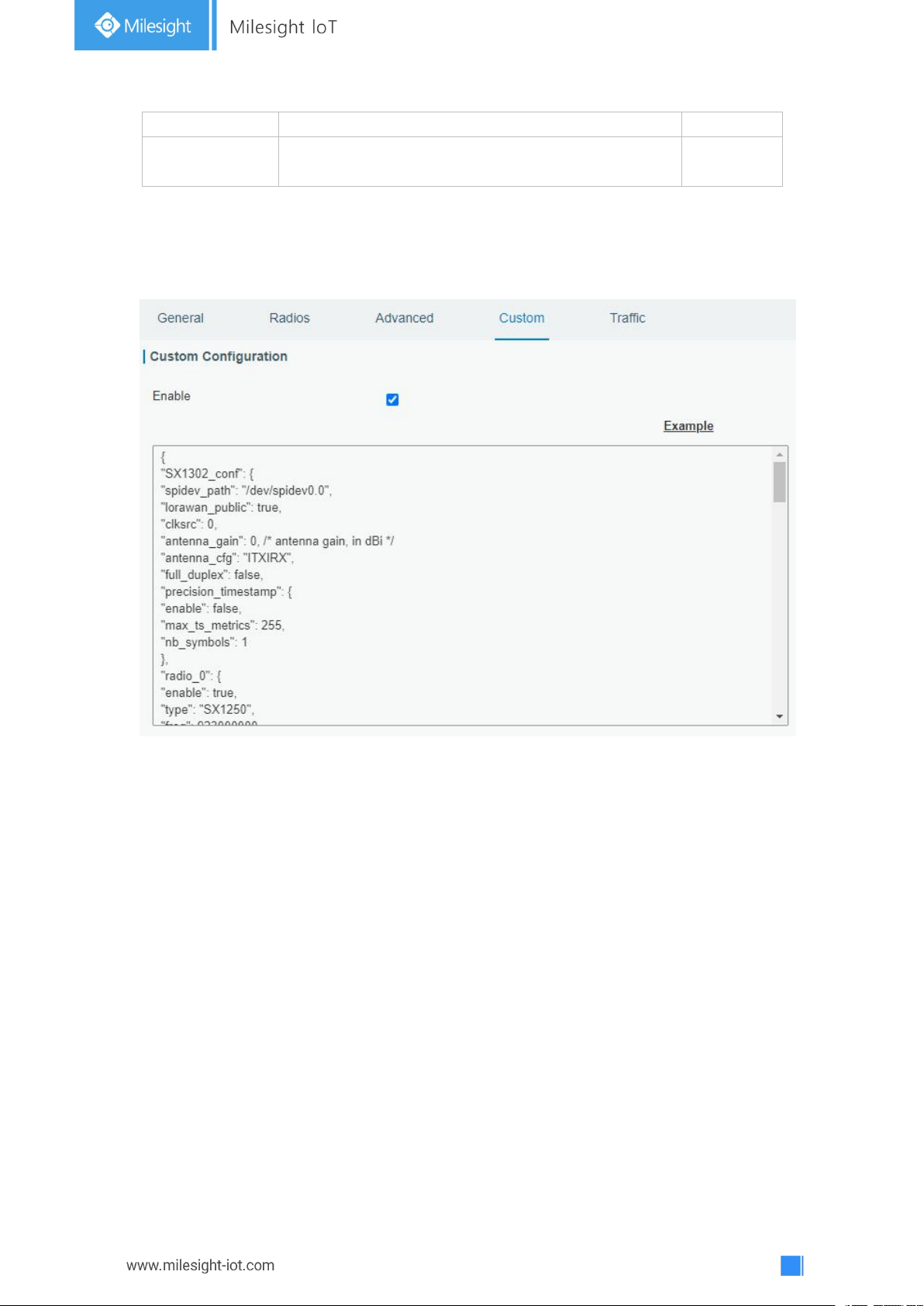
3.2.1.4 Custom
Table 3-2-1-6 Advanced Parameters
Figure 3-2-1-8
When Custom Configuration mode is enabled, you can write your own packet forwarder
configuration file in the edit box to configure packet forwarder. Click “Save” to save your
custom configuration file content, and click “Apply” to take effect. You can click “Clear” to
erase all content in the edit box. If you don’t know how to write configuration file, please
click “Example” to go to reference page.
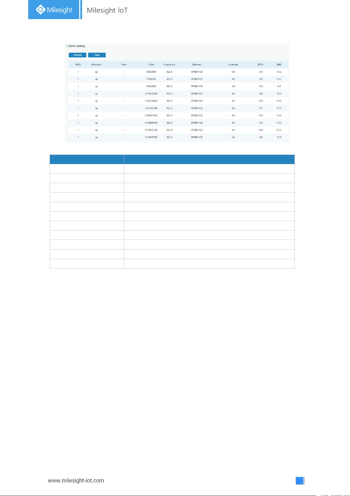
3.2.1.5 Traffic
When navigating to the traffic page, any recent traffic received by the gateway will display.
To watch live traffic, click Start.
Page 28
28
Figure 3-2-1-9
Item
Description
Refresh
Click to obtain the latest data.
Clear
Click to clear all data.
Rfch
Show the channel of this packet.
Direction
Show the direction of this packet.
Time
Show the receiving time of this packet.
Ticks
Show the ticks of this packet.
Frequency
Show the frequency of the channel.
Datarate
Show the datarate of the channel.
Coderate
Show the coderate of this packet.
RSSI
Show the received signal strength.
SNR
Show the signal to noise ratio of this packet.
Table 3-2-1-7 Traffic Parameters
Page 29
29
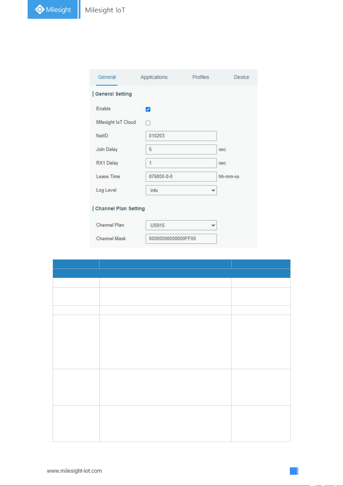
3.2.2 Network Server
Item
Description
Default
General Setting
Enable
Click to enable Network Server mode.
Enabled
Milesight IoT
Cloud
Enabled to connect gateway to Milesight IoT
Cloud.
Disabled
NetID
Enter the network identifier.
010203
Join Delay
Enter the interval time between when the
end-device sends a Join_request_message to
network server and when the end-device
prepares to open RX1 to receive the
Join_accept_message sent from network
server.
5
RX1 Delay
Enter the interval time between when the
end-device sends uplink packets and when the
end-device prepares to open RX1 to receive
the downlink packet.
1
Lease Time
Enter the amount of time till a successful join
expires. The format is hours-minutes-seconds.
If the join-type is OTAA, then the end-devices
need to join the network server again when it
876000-00-00
3.2.2.1 General
Figure 3-2-2-1
Page 30
30
exceeds the lease time.
Log level
Choose the log level.
Info
Channel Plan Setting
Channel Plan
Choose LoRaWAN®channel plan used for the
upstream and downlink frequencies and
datarates. Available channel plans depend on
the gateway’s model.
Depend on the
gateway’s model
Channel Mask
Enabled frequencies are controlled using
channel mask.
Leave it blank means using all the default
standard usable channels specified in the
LoRaWAN®regional parameters document.
A bit in the ChMask field set to 1 means that
the corresponding channel can be used for
uplink transmissions if this channel allows the
data rate currently used by the end-device.
A bit set to 0 means the corresponding
channels should be avoided.
US 915 and AU 915 have a 80-bit channel
mask for 72 usable channels and EU, AS, IN,
KR frequencies have a 16-bit mask for 16
usable channels.
Depend on the
gateway’s model
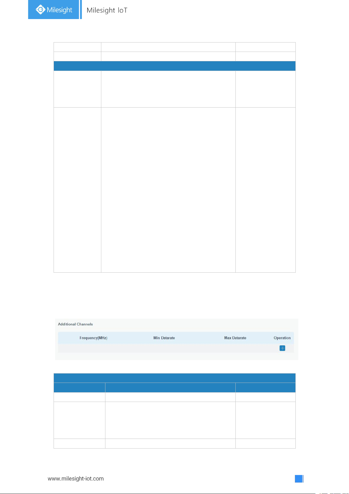
Note: For some regional variants, if allowed by your LoRaWAN®region, you can use
Additional Channels
Item
Description
Default
Frequency/MHz
Enter the frequency of the additional plan.
Null.
Max Datarate
Enter the max datarate for the end-device.
The range is based on what is specified in
the LoRaWAN®regional parameters
document.
DR0(SF12,125kHz)
Min Datarate
Enter the min datarate for the end-device.
DR3(SF9,125kHz)
Additional Plan to configure additional channels undefined by the LoRaWAN®Regional
Parameters, like EU868 and KR920, as the following picture shows:
Table 3-2-2-1 General Parameters
Figure 3-2-2-2
Page 31
31
The range is based on what is specified in
the LoRaWAN
®
regional parameters
document.
Table 3-2-2-2 Additional Plan Parameters
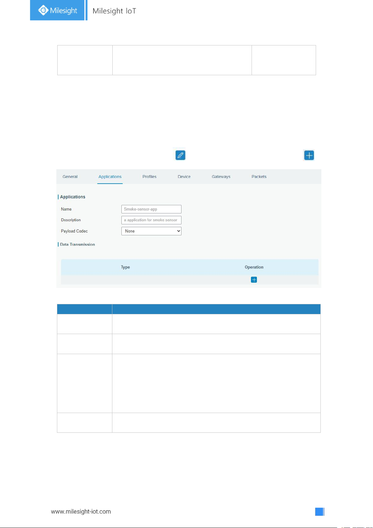
Item
Description
Name
Enter the name of the application profile.
E.g Smoker-sensor-app.
Description
Enter the description of this application.
E.g a application for smoker sensor.
Payload Codec
Select from: “None”, “Cayenne LPP”, “Custom”.
None: This mode enables devices not to encode data.
Cayenne LPP: This mode enables devices to encode data with the
Cayenne Low Power Payload (LPP).
Custom: This mode enables devices to encode data with the decoder
function and the encoder function which you have entered the code.
Data
Transmission
Data will be sent to your custom server using the MQTT,HTTP or
HTTPS protocol.
3.2.2.2 Application
An application is a collection of devices with the same purpose/of the same type. All
devices with the same “Payload Codec” and data transmission destination can be added
under the same application.
You can edit the application by clicking or create a new application by clicking .
Figure 3-2-2-3
Table 3-2-2-3 Application Parameters
Page 32
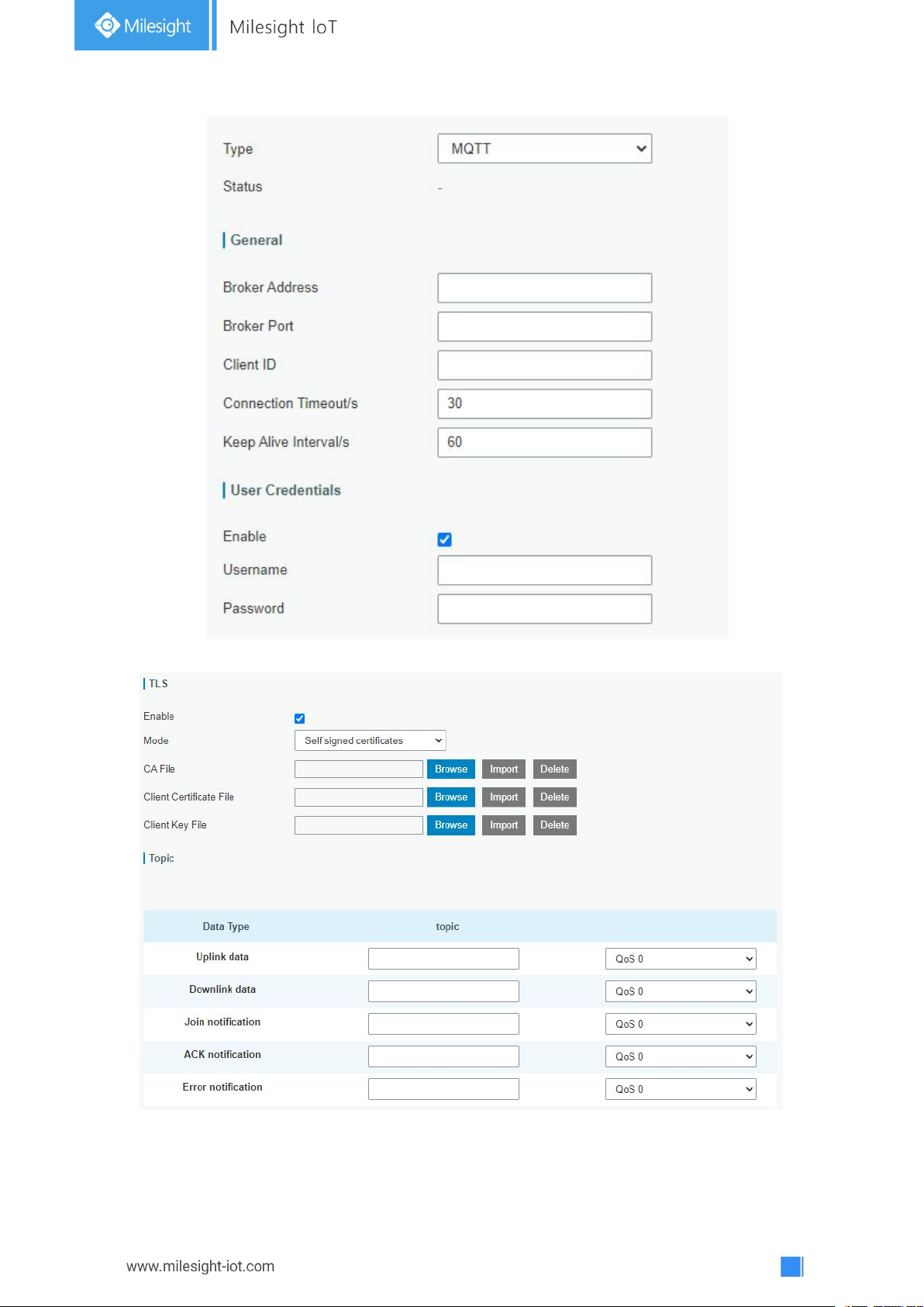
32
Figure 3-2-2-4
Figure 3-2-2-5
Page 33
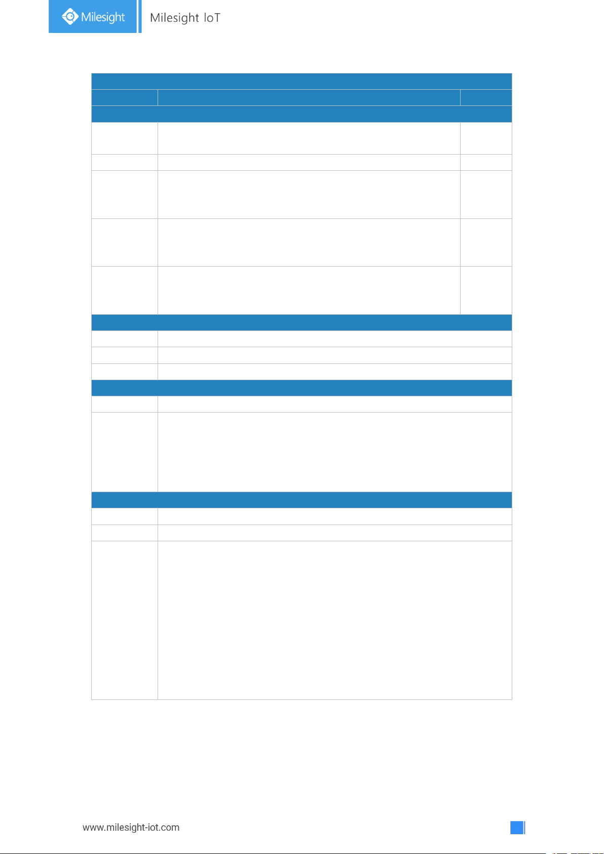
33
MQTT Settings
Item
Description
Default
General
Broker
Address
MQTT broker address to receive data.
-Broker Port
MQTT broker port to receive data.
--
Client ID
Client ID is the unique identity of the client to the server.
It must be unique when all clients are connected to the same
server, and it is the key to handle message at QoS 1 and 2.
--
Connection
Timeout/s
If the client does not get a response after the connection
timeout, the connection will be considered as broken. The
Range: 1-65535
30
Keep Alive
Interval/s
After the client is connected with the server, the client will
send heartbeat packet to the server regularly to keep alive.
Range: 1-65535
60
User Credentials
Enable
Enable user credentials.
Username
The username used for connecting to MQTT broker.
Password
The password used for connecting to MQTT broker.
TLS
Enable
Enable the TLS encryption in MQTT communication.
Mode
Select from “Self signed certificates”, “CA signed server certificate”.
CA signed server certificate:verify with the certificate issued by
Certificate Authority (CA) that pre-loaded on device.
Self signed certificates: upload the custom CA certificates, client
certificates and secret key for verification.
Topic
Data Type
Data type sent to MQTT broker.
Topic
Topic name of the data type using for publish.
QoS
QoS 0 – Only Once
This is the fastest method and requires only 1 message. It is also the
most unreliable transfer mode.
QoS 1 – At Least Once
This level guarantees that the message will be delivered at least once,
but may be delivered more than once.
QoS 2 – Exactly Once
QoS 2 is the highest level of service in MQTT. This level guarantees that
each message is received only once by the intended recipients. QoS 2 is
the safest and slowest quality of service level.
Table 3-2-2-4 MQTT Settings Parameters
Page 34
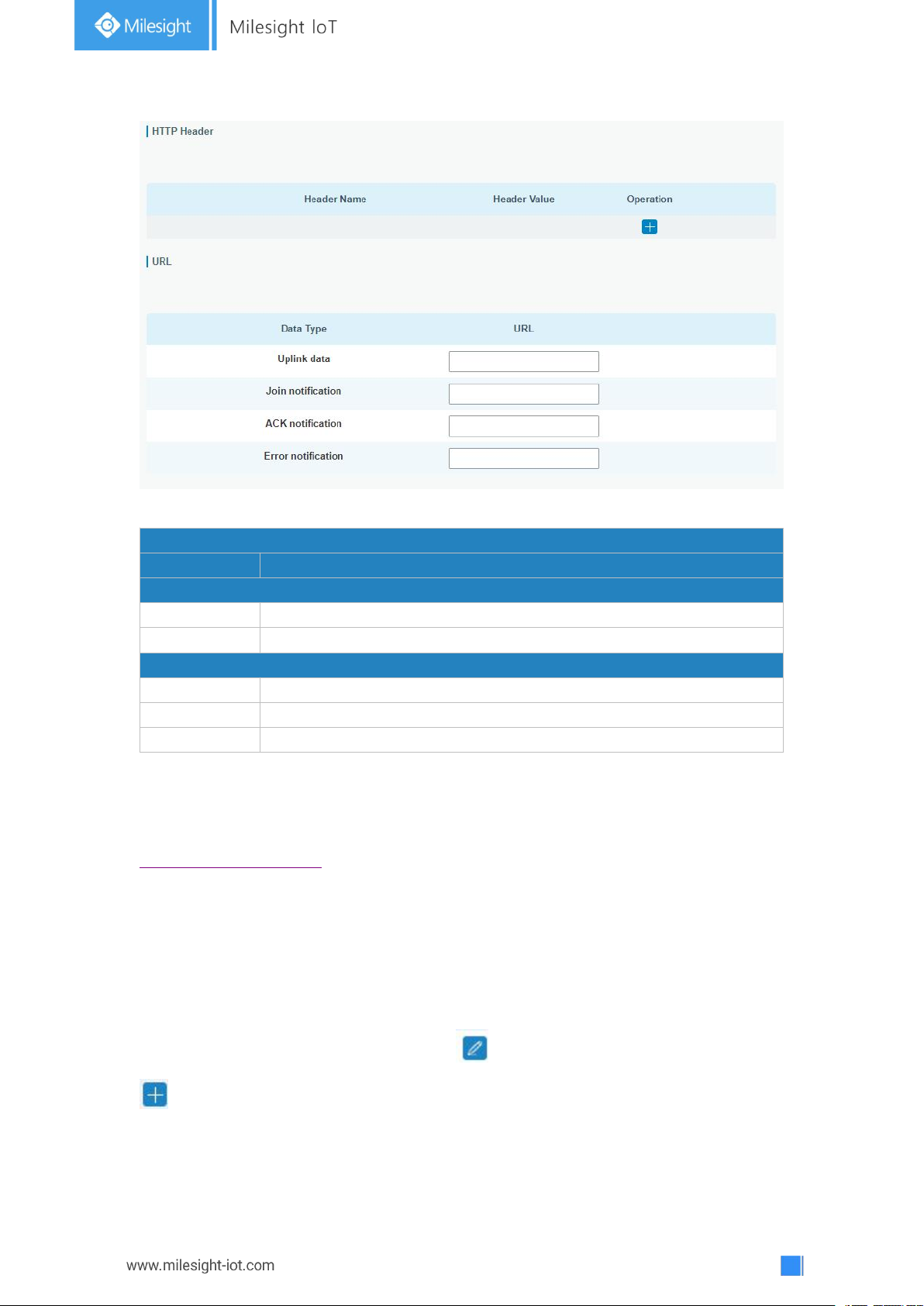
34
HTTP/HTTPS Settings
Item
Description
HTTP Header
Header Name
A core set of fields in HTTP header.
Header Value
Value of the HTTP header.
URL
Data Type
Data type sent to HTTP/HTTPS server.
Topic
Topic name of the data type using for publish.
URL
HTTP/HTTPS server URL to receive data.
Table 3-2-2-5 HTTP/HTTPS Settings Parameters
Related Configuration Example
Application configuration
3.2.2.3 Profiles
Figure 3-2-2-6
A Profile defines the device capabilities and boot parameters that are needed by the Netwo
rk Server for setting the LoRaWAN®radio access service. These information elements
shall be provided by the end-device manufacturer.
You can edit the device profile by clicking or create a new device profile by clicking
.
Page 35
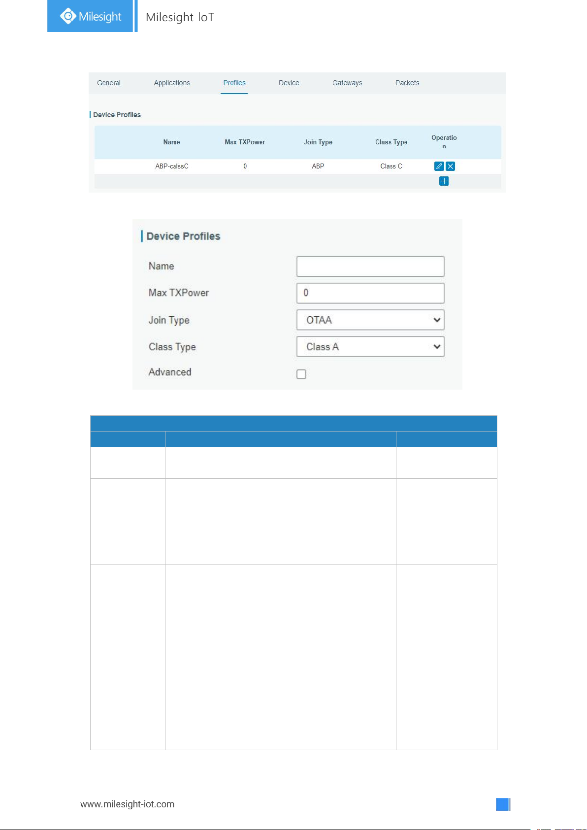
35
Figure 3-2-2-7
Device Profiles Settings
Item
Description
Default
Name
Enter the name of the device profile.
E.g. Smoker-sensor-app.
Null
Max
TXPower
Enter the maximum transmit power.
The TXPower indicates power levels relative to
the Max EIRP level of the end-device.
0 means using the max EIRP. EIRP refers to the
Equivalent Isotropically Radiated Power.
0
Join Type
Select from: “OTAA” and “ABP”.
OTAA:Over-the-Air Activation.
For over-the-air activation, end-devices must
follow a join procedure prior to participating in
data exchanges with the network server. An
end-device has to go through a new join
procedure every time as it has lost the session
context information.
ABP: Activation by Personalization.
Under certain circumstances, end-devices can
be activated by personalization. Activation by
OTAA
Figure 3-2-2-8
Page 36
36
personalization directly ties an end-device to a
specific network bypassing the join request join accept procedure.
Class Type
Select from: “Class A” and “Class C”.
Class A: Class A operation has the lowest
power consumption for applications that
require downlink communication from the
server shortly after the end-device has sent an
uplink transmission.
Class C: End-device of Class C will continuously
open receive windows, only closed when
transmitting. Class C end-device will spend
more power than Class A or Class B but they
offer the lowest latency for server to end-device
communication.
Class A
Table 3-2-2-6 Device Profiles Setting Parameters
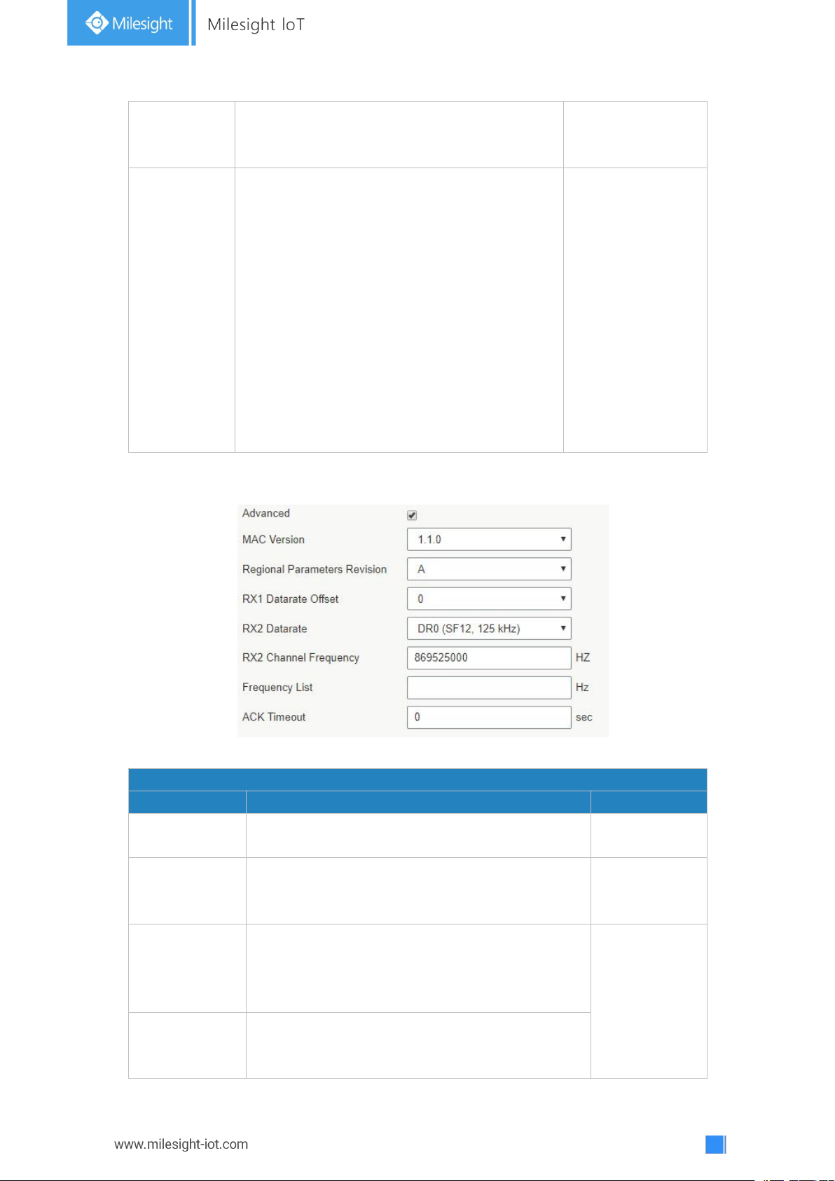
Device Profile Advanced Settings
Item
Description
Default
MAC Version
Choose the version of the LoRaWAN®supported
by the end-device.
1.0.2
Regional
Parameter
Revision
Revision of the Regional Parameters document
supported by the end-device.
B
RX1 Datarate
Offset
Enter the offset which used for calculate the RX1
data-rate, based on the uplink data-rate.
The range is based on what is specified in the
LoRaWAN®regional parameters document.
Based on what
is specified in
the LoRaWAN
®
regional
parameters
document
RX2 Datarate
Enter the RX2 datarate which used for the RX2
receive-window. The range is based on what is
specified in the LoRaWAN®regional parameters
Figure 3-2-2-9
Page 37
37
document.
RX2 Channel
Frequency
Enter the RX2 channel frequency which used for
the RX2 receive-window. The range is based on
what is specified in the LoRaWAN®regional
parameters document.
Frequency List
List of factory-preset frequencies. The range is
based on what is specified in the LoRaWAN
®
regional parameters document.
Null
ACK Timeout
Enter the time for confirmed downlink
transmissions. Only applicable to class C.
0
Table 3-2-2-7 Device Profiles Advanced Setting Parameters
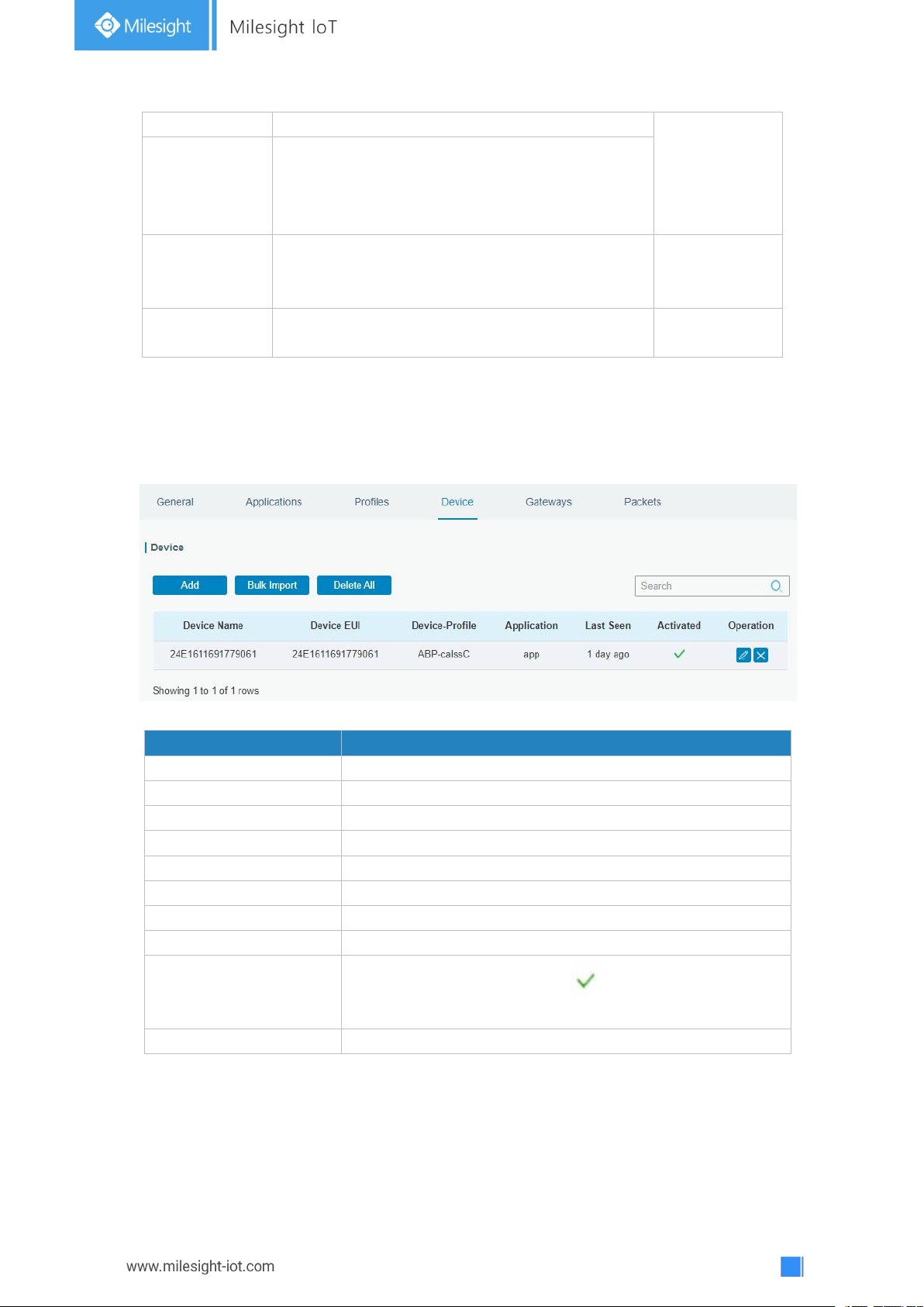
Item
Description
Add
Add a device.
Bulk Import
Download template and import multiple devices.
Delete All
Delete all devices in the list.
Device Name
Show the name of the device.
Device EUI
Show the EUI of the device.
Device-Profile
Show the name of the device’s device profile.
Application
Show the name of the device’s application.
Last Seen
Show the time of last packet received.
Activated
Show the status of the device . means that the device
has been activated.
Operation
Edit or delete the device.
3.2.2.4 Device
A device is the end-device connecting to, and communicating over the LoRaWAN®network.
Figure 3-2-2-10
Table 3-2-2-8 Device Parameters
Page 38
38
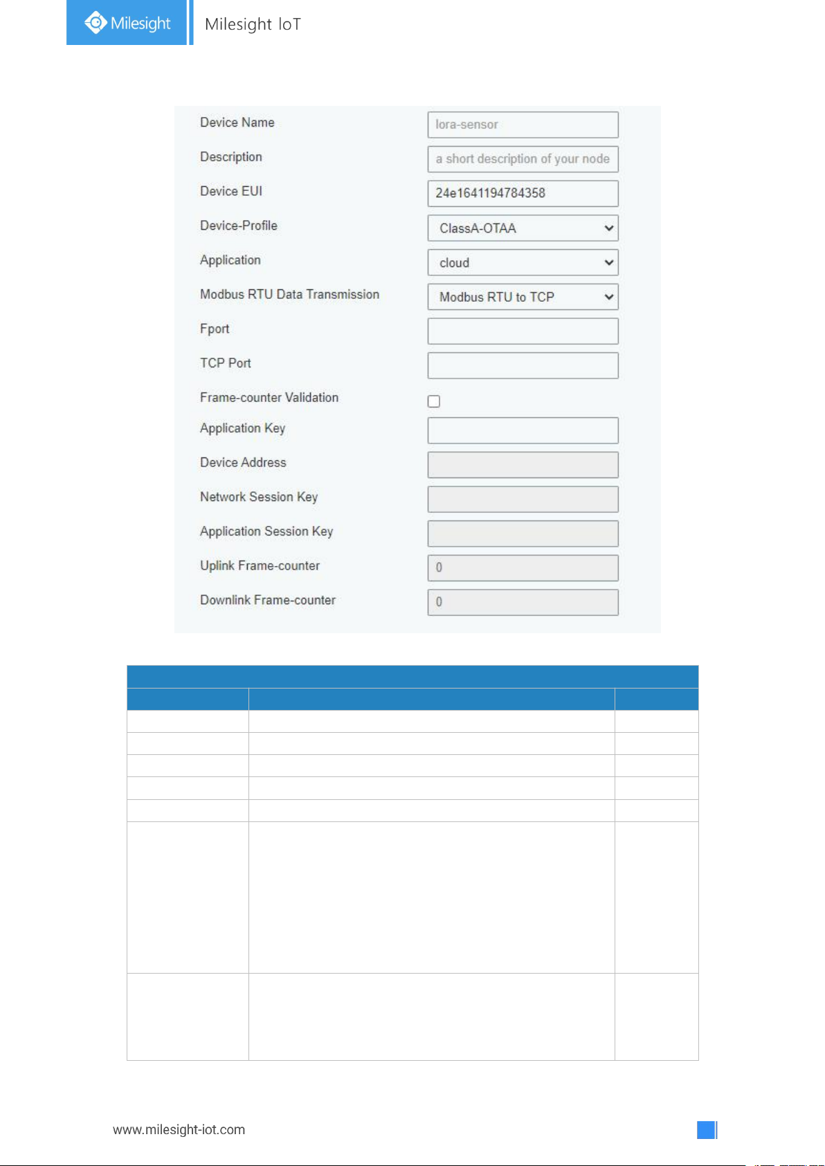
Device Configuration
Item
Description
Default
Device Name
Enter the name of this device.
Null
Description
Enter the description of this device.
Null
Device EUI
Enter the EUI of this device.
Null
Device-Profile
Choose the device profile.
Null
Application
Choose the application profile.
Null
Modbus RTU
Data
Transmission
Choose from: "Disable", "Modbus RTU to TCP",
"Modbus RTU over TCP". This feature is only
applicable to Milesight LoRaWAN®controllers.
-Modbus RTU to TCP: TCP client can send Modbus
TCP commands to ask for controller Modbus data.
-Modbus RTU over TCP: TCP client can send Modbus
RTU commands to ask for controller Modbus data.
Disable
Fport
Enter the LoRaWAN®frame port for transparent
transmission between Milesight LoRaWAN
®
controllers and UG67.
Range: 2-84, 86-223.
Null
Figure 3-2-2-11
Page 39

39
Note: this value must be the same as the Milesight
LoRaWAN®controller’s Fport.
TCP Port
Enter the TCP port for data transmission between the
TCP Client and UG67 (as TCP Server).
Range: 1-65535.
Null
Frame-Counter
Validation
If disable the frame-counter validation, it will
compromise security as it enables people to perform
replay-attacks.
Enabled
Application Key
Whenever an end-device joins a network via
over-the-air activation, the application key is used for
derive the Application Session key.
Null
Device Address
The device address identifies the end-device within
the current network.
Null
Network
Session Key
The network session key specific for the end-device. It
is used by the end-device to calculate the MIC or part
of the MIC (message integrity code) of all uplink data
messages to ensure data integrity.
Null
Application
Session Key
The AppSKey is an application session key specific for
the end-device. It is used by both the application
server and the end-device to encrypt and decrypt the
payload field of application-specific data messages.
Null
Uplink
Frame-counter
The number of data frames which sent uplink to the
network server. It will be incremented by the
end-device and received by the end-device.
Users can reset the a personalized end-device
manually, then the frame counters on the end-device
and the frame counters on the network server for that
end-device will be reset to 0.
Null
Downlink
Frame-counter
The number of data frames which received by the
end-device downlink from the network server. It will be
incremented by the network server.
Users cloud reset the a personalized end-device
manually, then the frame counters on the end-device
and the frame counters on the network server for that
end-device will be reset to 0.
Null
Table 3-2-2-9 Device Setting Parameters
Related Configuration Example
Device configuration
Page 40
40
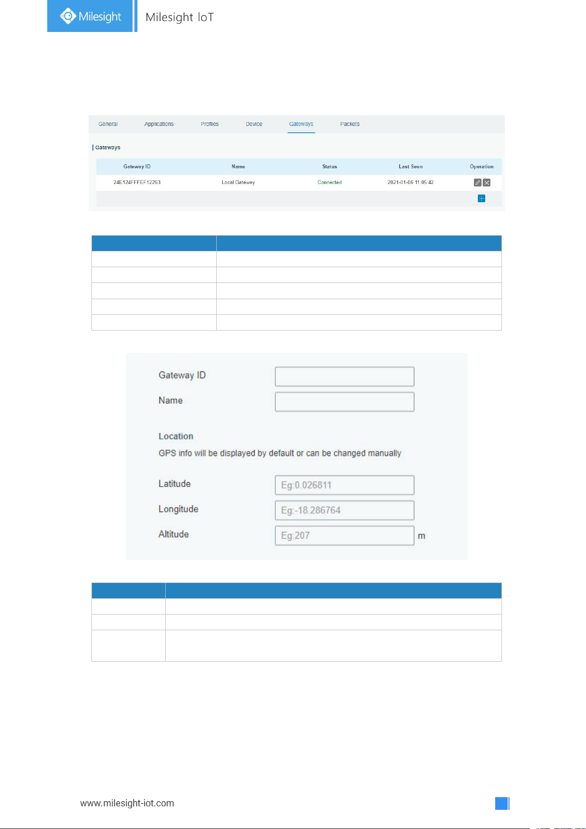
3.2.2.5 Gateway
Item
Description
Gateway ID
Show the gateway ID.
Name
Show the name of the gateway.
Status
Show the connection status of the gateway.
Last Seen
Show the time of last packet received.
Operation
Edit or delete the gateway.
Item
Description
Gateway ID
Enter the unique gateway ID to recognize the gateway.
Name
Enter the name of this gateway.
Location
GPS data of the gateway can be edited here. If gateway sends GPS
data it will replace your customized data.
Other gateways can connect to UG67 network server.
Figure 3-2-2-12
Table 3-2-2-11 Gateway Parameters
Figure 3-2-2-13
Table 3-2-2-12 Gateway Setting Parameters
Page 41
41
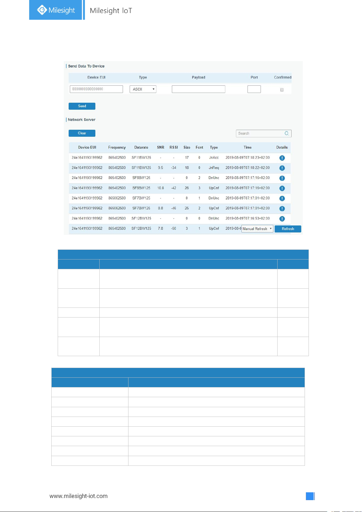
3.2.2.6 Packets
Send Data To Device
Item
Description
Default
Device EUI
Enter the EUI of the device to receive
the payload.
Null
Type
Choose from: “ASCII”, “hex”, “base64”.
Choose the payload type to enter in the payload Input box.
ASCII
Payload
Enter the message to be sent to this device.
Null
Port
Enter the LoRaWAN®frame port for packet transmission
between device and Network Server.
Null
Confirmed
After enabled, the end device will receive downlink packet
and should answer “confirmed” to the network server.
Disabled
Network Server
Item
Description
Device EUI
Show the EUI of the device.
Frequency
Show the used frequency to transmit packets.
Datarate
Show the used datarate to transmit packets.
SNR
Show the signal-noise ratio.
RSSI
Show the received signal strength indicator.
Size
Show the size of payload.
Fcnt
Show the frame counter.
Type
Show the type of the packet:
Figure 3-2-2-14
Table 3-2-2-13 Send Data to Device Parameters
Page 42
42
JnAcc - Join Accept Packet
JnReq - Join Request Packet
UpUnc - Uplink Unconfirmed Packet
UpCnf - Uplink Confirmed Packet - ACK response from
network requested
DnUnc - Downlink Unconfirmed Packet
DnCnf - Downlink Confirmed Packet- ACK response from
end-device requested
Time
Show the time of packet was sent or received.
Table 3-2-2-14 Packet Parameters
Item
Description
Dev Addr
Show the address of the device.
GwEUI
Show the EUI of the gateway.
AppEUI
Show the EUI of the application.
DevEUI
Show the EUI of the device.
Immediately
True: Device may transmit an explicit (possibly empty)
acknowledgement data message immediately after the reception of a
data message requiring a confirmation.
TimeSinceGP
SEpoch
Show the GPS time.
Timestamp
Show the timestamp of this packet.
Frequency
Show the frequency of this channel.
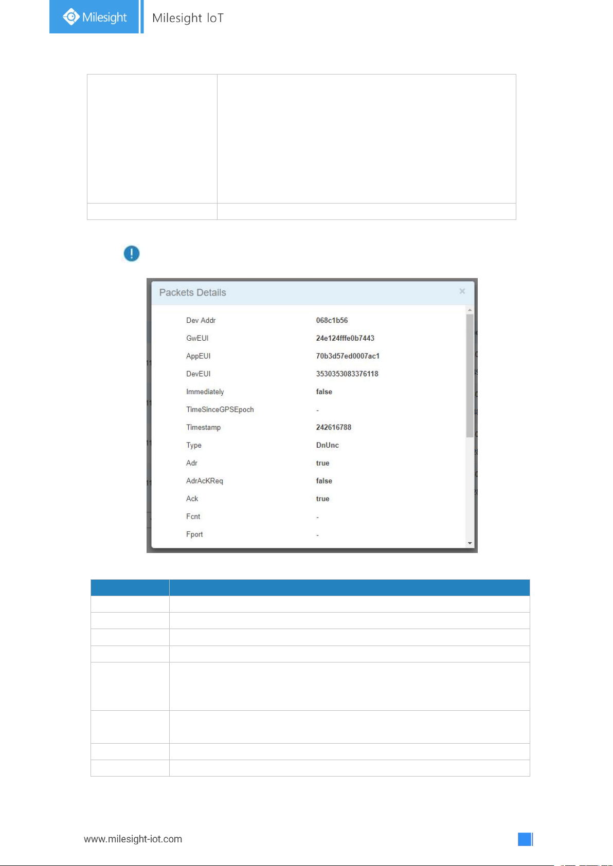
Click to get more details about the packet. As shown:
Figure 3-2-2-15
Page 43

43
Type
Show the type of the packet:
JnAcc - Join Accept Packet
JnReq - Join Request Packet
UpUnc - Uplink Unconfirmed Packet
UpCnf - Uplink Confirmed Packet - ACK response from network
requested
DnUnc - Downlink Unconfirmed Packet
DnCnf - Downlink Confirmed Packet- ACK response from end-device
requested
Adr
True: The end-node has enabled ADR.
False: The end-node has not enabled ADR.
AdrAcKReq
In order to validate that the network is receiving the uplink messages,
nodes periodically transmit ADRACKReq message. This is 1 bit long.
True: Network should respond in ADR_ACK_DELAY time to confirm that it
is receiving the uplink messages.
False: ADR is disabled or Network does not respond in ADR_ACK_DELAY.
Ack
True: This frame is ACK.
False: This frame is not ACK.
Fcnt
Show the frame-counter of this packet.The network server tracks the
uplink frame counter and generates the
downlink counter for each end-device.
FPort
FPort is a multiplexing port field. If the frame payload field is not empty,
the port field must be present. If present, a FPort
16 value of 0 indicates that the FRMPayload contains MAC commands
only.When this is the case, the FOptsLen field must be zero. FOptsLen is
the length of the FOpts field in bytes.
Modulation
LoRa means the physical layer uses the LoRa modulation
Bandwidth
Show the bandwidth of this channel.
SpreadFactor
Show the spreadFactor of this channel.
Bitrate
Show the bitrate of this channel.
CodeRate
Show the coderate of this channel.
SNR
Show the SNR of this channel.
RSSI
Show the RSSI of this channel.
Power
Show the transmit power of the device.
Payload (b64)
Show the application payload of this packet.
Payload (hex)
Show the application payload of this packet.
MIC
Show the MIC of this packet.MIC is a cryptographic message integrity
code, computed over the fields MHDR, FHDR, FPort and the encrypted
FRMPayload.
Table 3-2-2-15 Packets Details Parameters
Related Topic
Send Data to Device
Page 44
44
3.3 Network
Port Setting
Item
Description
Default
Enable
Enable WAN function.
Enable
Port
The port that is currently set as eth0 port.
eth 0
Connection
Type
Select from "Static IP", "DHCP Client" and "PPPoE".
Static IP
MTU
Set the maximum transmission unit.
1500
Primary DNS
Server
Set the primary DNS.
Null
Secondary DNS
Server
Set the secondary DNS.
Null
Enable NAT
Enable or disable NAT function. When enabled, a
private IP can be translated to a public IP.
Enable
3.3.1 Interface
3.3.1.1 Port
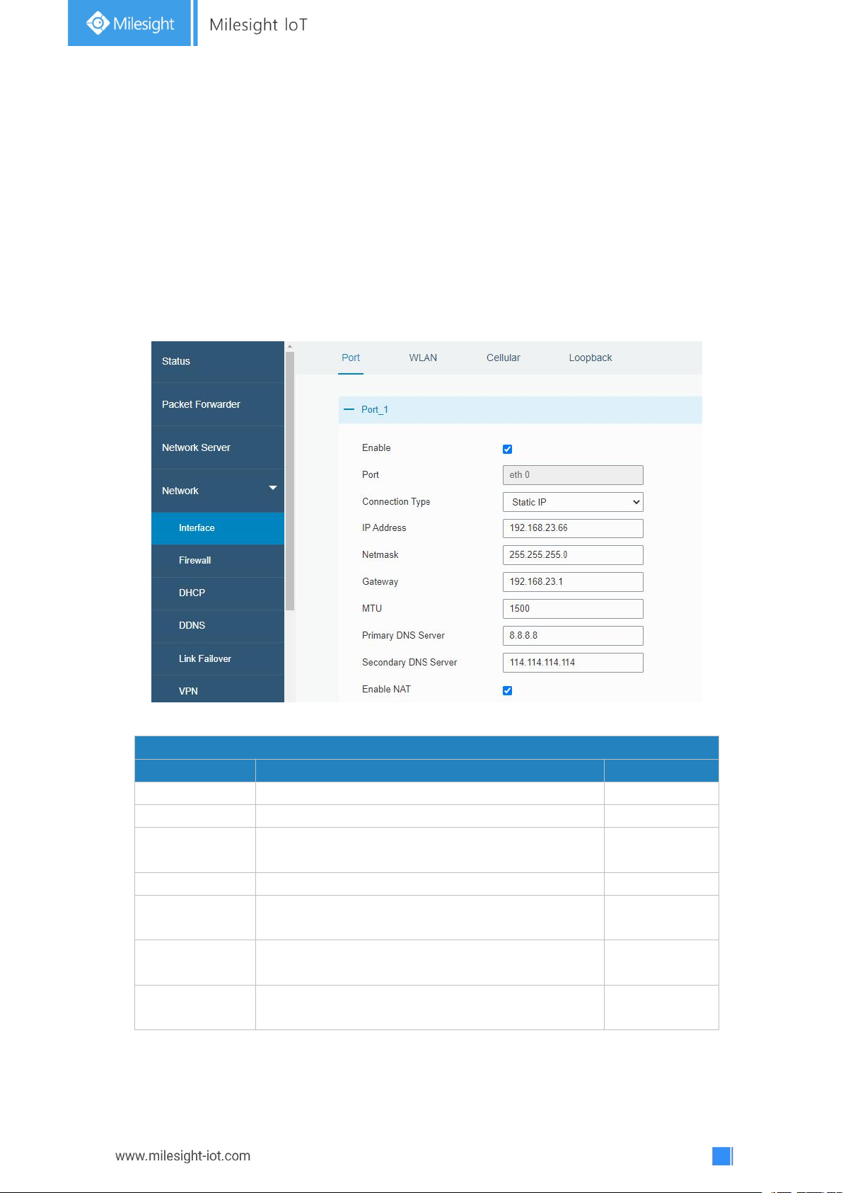
The Ethernet port can be connected with Ethernet cable to get Internet access. It supports
3 connection types.
- Static IP: configure IP address, netmask and gateway for Ethernet WAN interface.
- DHCP Client: configure Ethernet WAN interface as DHCP Client to obtain IP address
automatically.
- PPPoE: configure Ethernet WAN interface as PPPoE Client.
Figure 3-3-1-1
Table 3-3-1-1 Port Parameters
Page 45
45
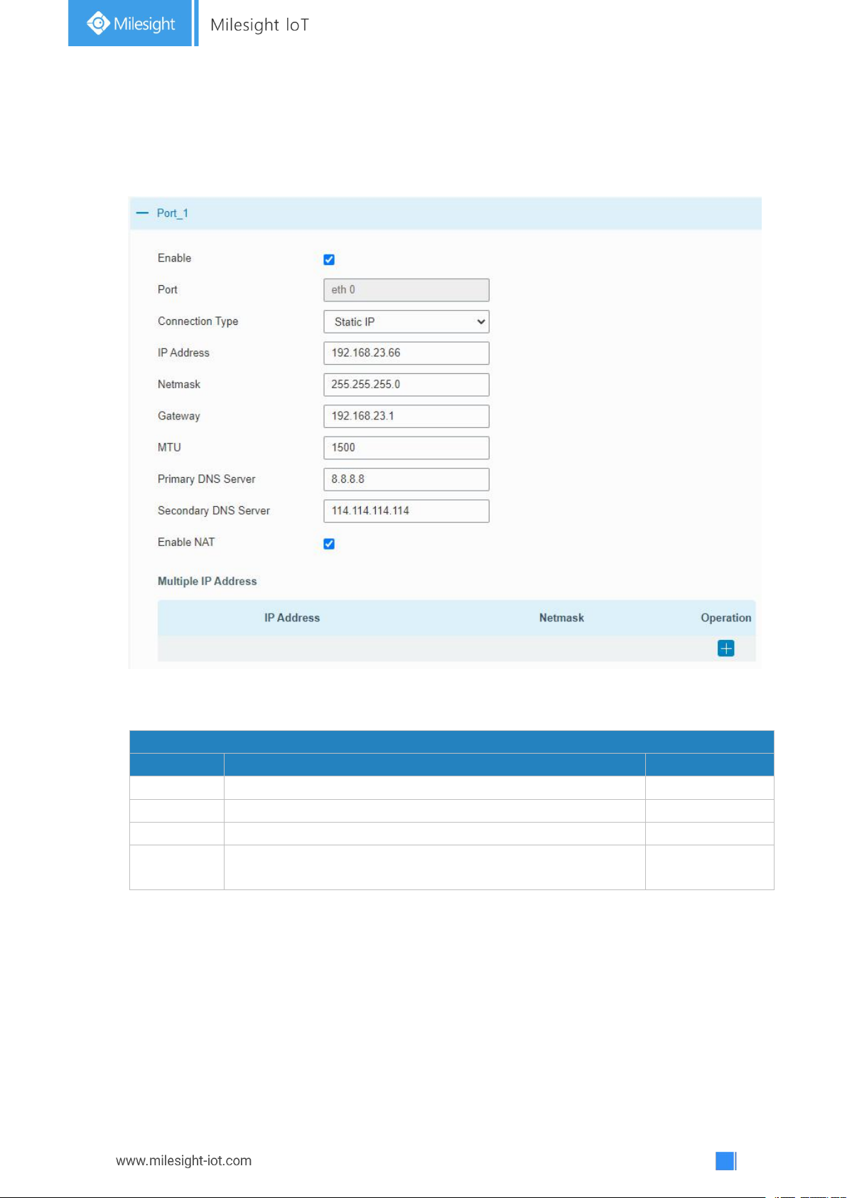
1. Static IP Configuration
Static IP
Item
Description
Default
IP Address
Set the IP address which can access Internet.
192.168.23.150
Netmask
Set the Netmask for Ethernet port.
255.255.255.0
Gateway
Set the gateway's IP address for Ethernet port.
192.168.23.1
Multiple IP
Address
Set the multiple IP addresses for Ethernet port.
Null
If the external network assigns a fixed IP for the Ethernet port, user can select “Static IP”
mode.
Figure 3-3-1-2
Table 3-3-1-2 Static IP Parameters
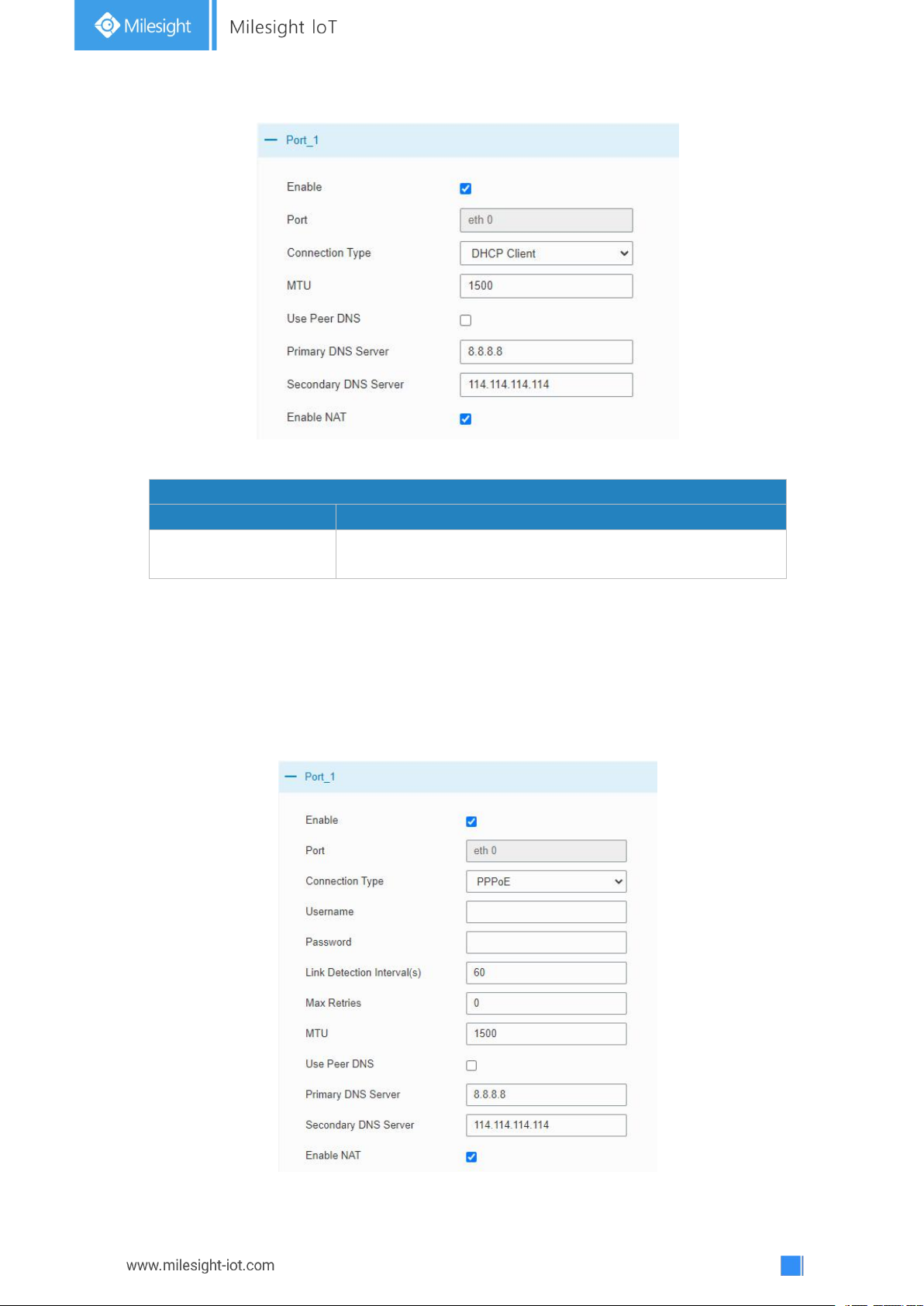
2. DHCP Client
If the external network has DHCP server enabled and has assigned IP addresses to the
Ethernet WAN interface, user can select “DHCP client” mode to obtain IP address
automatically.
Page 46
46
Figure 3-3-1-3
DHCP Client
Item
Description
Use Peer DNS
Obtain peer DNS automatically during PPP dialing. DNS is
necessary when user visits domain name.
Table 3-3-1-3 DHCP Client Parameters
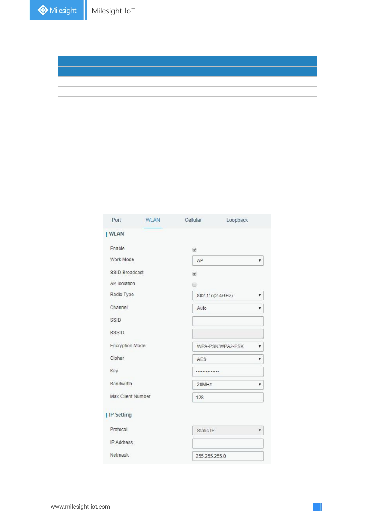
3. PPPoE
PPPoE refers to a point to point protocol over Ethernet. User has to install a PPPoE client
on the basis of original connection way. With PPPoE, remote access devices can get
control of each user.
Page 47
47
Figure 3-3-1-4
PPPoE
Item
Description
Username
Enter the username provided by your Internet Service Provider (ISP).
Password
Enter the password provided by your Internet Service Provider (ISP).
Link Detection
Interval (s)
Set the heartbeat interval for link detection. Range: 1-600.
Max Retries
Set the maximum retry times after it fails to dial up. Range: 0-9.
Use Peer DNS
Obtain peer DNS automatically during PPP dialing. DNS is necessary
when user visits domain name.
Table 3-3-1-4 PPOE Parameters
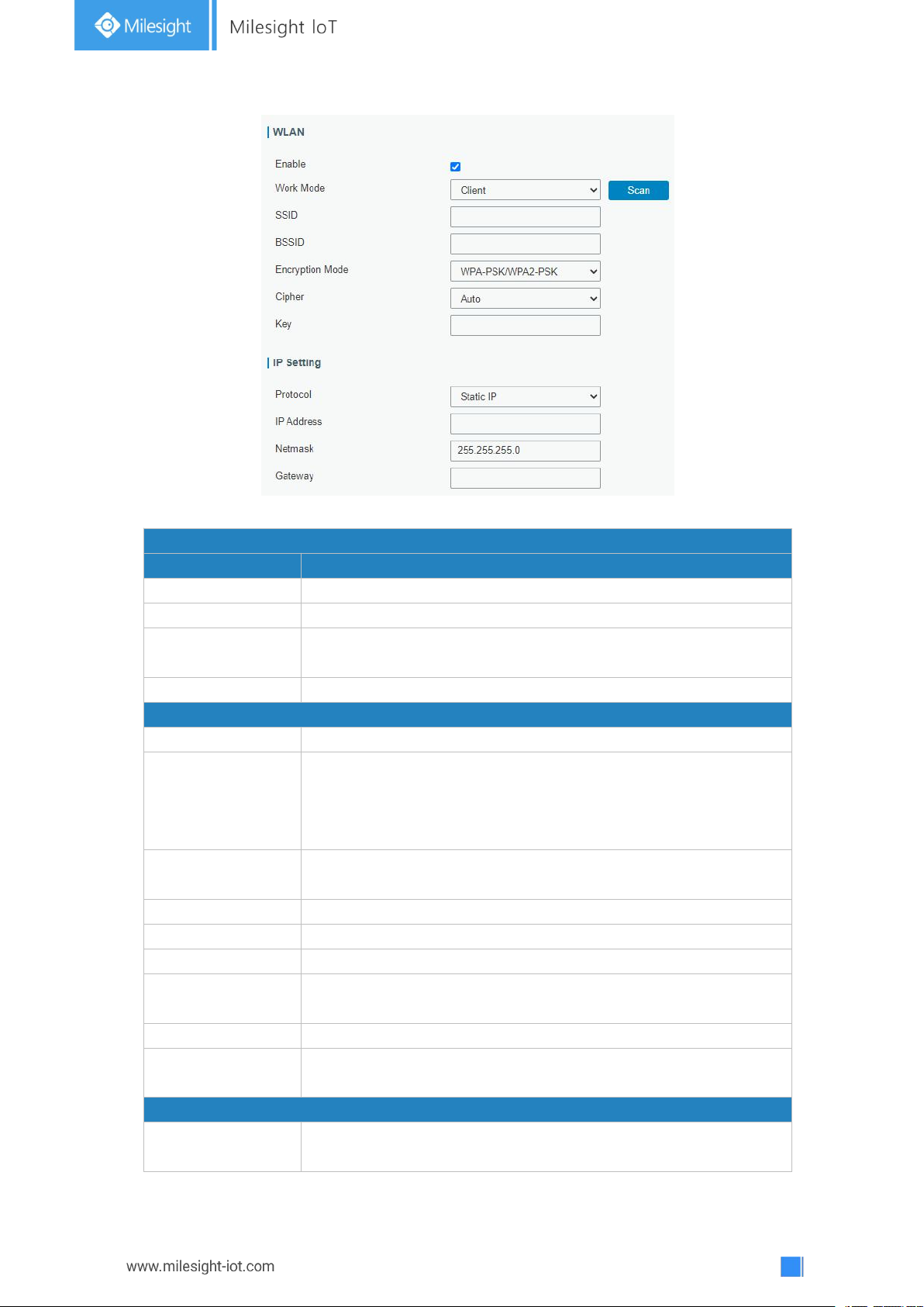
3.3.1.2 WLAN
This section explains how to set the related parameters for Wi-Fi network. UG67 supports
802.11 b/g/n, as AP or client mode.
Figure 3-3-1-5
Page 48
48
Figure 3-3-1-6
WLAN Settings
Item
Description
Enable
Enable/disable WLAN.
Work Mode
Select gateway's work mode. The options are "Client" or "AP".
BSSID
Fill in the MAC address of the access point. Either SSID or BSSID
can be filled to joint the network.
SSID
Fill in the SSID of the access point.
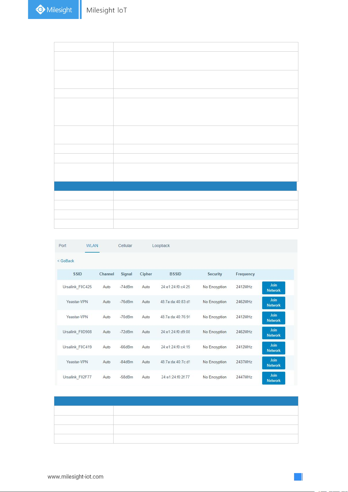
Client Mode
Scan
Click "Scan" button to search the nearby access point.
Encryption Mode
Select encryption mode. The options are “No Encryption", “WEP
Open System" , “WEP Shared Key", “WPA-PSK", “WPA2-PSK" ,
“WPA-PSK/WPA2-PSK", “WPA-Enterprise”, “WPA2-Enterprise”and
“WPA-Enterprise/WPA2-Enterprise”.
Cipher
Select cipher. The options are “Auto", “AES", “TKIP" and
“AES/TKIP".
Key
Fill the pre-shared key of WEP/WPA encryption.
XSupplicant Type
Select from “Peap”, “Leap”, “TLS” and “TTLS”.
User
Fill the user of WPA/WPA2-Enterprise.
Anonymous
Identity
Fill the anonymous identity of WPA/WPA2-Enterprise.
Phase2
Fill the phase2 of WPA/WPA2-Enterprise.
Public Server
Certificate
The public server certificate used for verifying with
WPA/WPA2-Enterprise access point.
AP Mode
SSID Broadcast
When SSID broadcast is disabled, other wireless devices can't not
find the SSID, and users have to enter the SSID manually to
Page 49
49
access to the wireless network.
AP Isolation
When AP isolation is enabled, all users which access to the AP
are isolated without communication with each other.
Radio Type
Select Radio type. The options are “802.11b (2.4 GHz)", “802.11g
(2.4 GHz)", “802.11n (2.4 GHz)””.
Channel
Select wireless channel. The options are "Auto", "1", "2"......"11".
Encryption Mode
Select encryption mode. The options are “No Encryption", “WEP
Open System" , “WEP Shared Key", “WPA-PSK", “WPA2-PSK" and
“WPA-PSK/WPA2-PSK".
Cipher
Select cipher. The options are “Auto", “AES", “TKIP" and
“AES/TKIP".
Key
Fill the pre-shared key of WPA encryption.
Bandwidth
Select bandwidth. The options are "20MHz" and "40MHz".
Max Client Number
Set the maximum number of client to access when the gateway
is configured as AP.
IP Setting
Protocol
Set the protocol in wireless network.
IP Address
Set the IP address in wireless network.
Netmask
Set the netmask in wireless network.
Gateway
Set the gateway in wireless network.
Table 3-3-1-5 WLAN Parameters
Client Mode-Scan
SSID
Show SSID.
Channel
Show wireless channel.
Signal
Show wireless signal.
BSSID
Show the MAC address of the access point.
Figure 3-3-1-7
Page 50
50
Security
Show the encryption mode.
Frequency
Show the frequency of radio.
Join Network
Click the button to join the wireless network.
Table 3-3-1-6 WLAN Scan Parameters
Related Topic
Wi-Fi Application Example
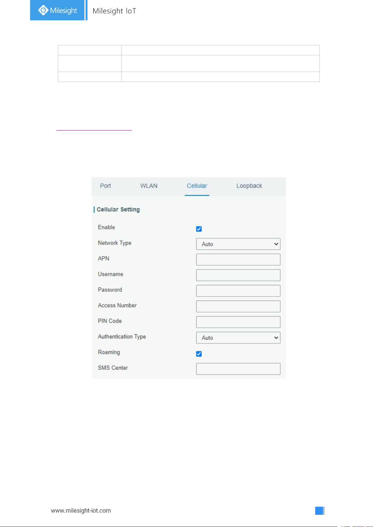
3.3.1.3 Cellular
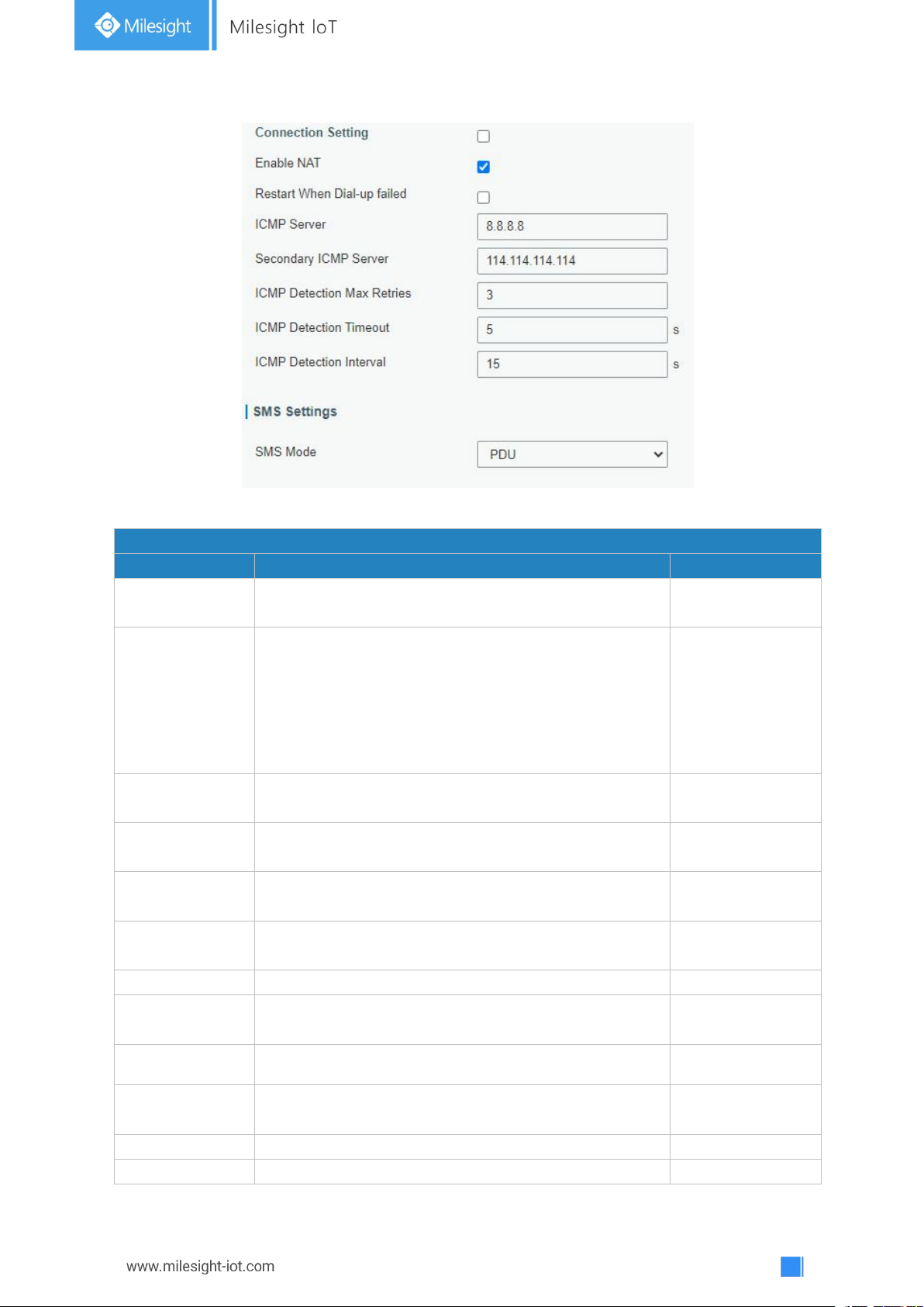
This section explains how to set the related parameters for cellular network.
Figure 3-3-1-8
Page 51
51
Figure 3-3-1-9
General Settings
Item
Description
Default
Enable
Check the option to enable the corresponding SIM
card.
Enable
Network Type
Select from "Auto”, "Auto 3G/4G”, "4G Only" and "3G
Only".
Auto: connect to the network with the strongest signal
automatically.
4G Only: connect to 4G network only.
And so on.
Auto
APN
Enter the Access Point Name for cellular dial-up
connection provided by local ISP.
Null
Username
Enter the username for cellular dial-up connection
provided by local ISP.
Null
Password
Enter the password for cellular dial-up connection
provided by local ISP.
Null
Access Number
Enter the dial-up center NO. For cellular dial-up
connection provided by local ISP.
Null
PIN Code
Enter a 4-8 characters PIN code to unlock the SIM.
Null
Authentication
Type
Select from "Auto", "PAP", "CHAP", "MS-CHAP", and
"MS-CHAPv2".
Auto
Roaming
Enable or disable roaming.
Disable
SMS Center
Enter the local SMS center number for storing,
forwarding, converting and delivering SMS message.
Null
Enable NAT
Enable or disable NAT function.
Enable
Restart When
When this function is enabled, the gateway will restart
Disabled
Page 52
52
Dial-up failed
automatically if the dial-up fails several times.
ICMP Server
Set the ICMP detection server's IP address.
8.8.8.8
Secondary ICMP
Server
Set the secondary ICMP detection server's IP address.
114.114.114.114
ICMP Detection
Max Retries
Set max number of retries when ICMP detection fails.
3
ICMP Detection
Timeout
Set timeout of ICMP detection.
5
ICMP Detection
Interval
Set interval of ICMP detection.
15
SMS Mode
Select SMS mode from “TEXT” and “PDU”.
PDU
Table 3-3-1-7 Cellular Parameters
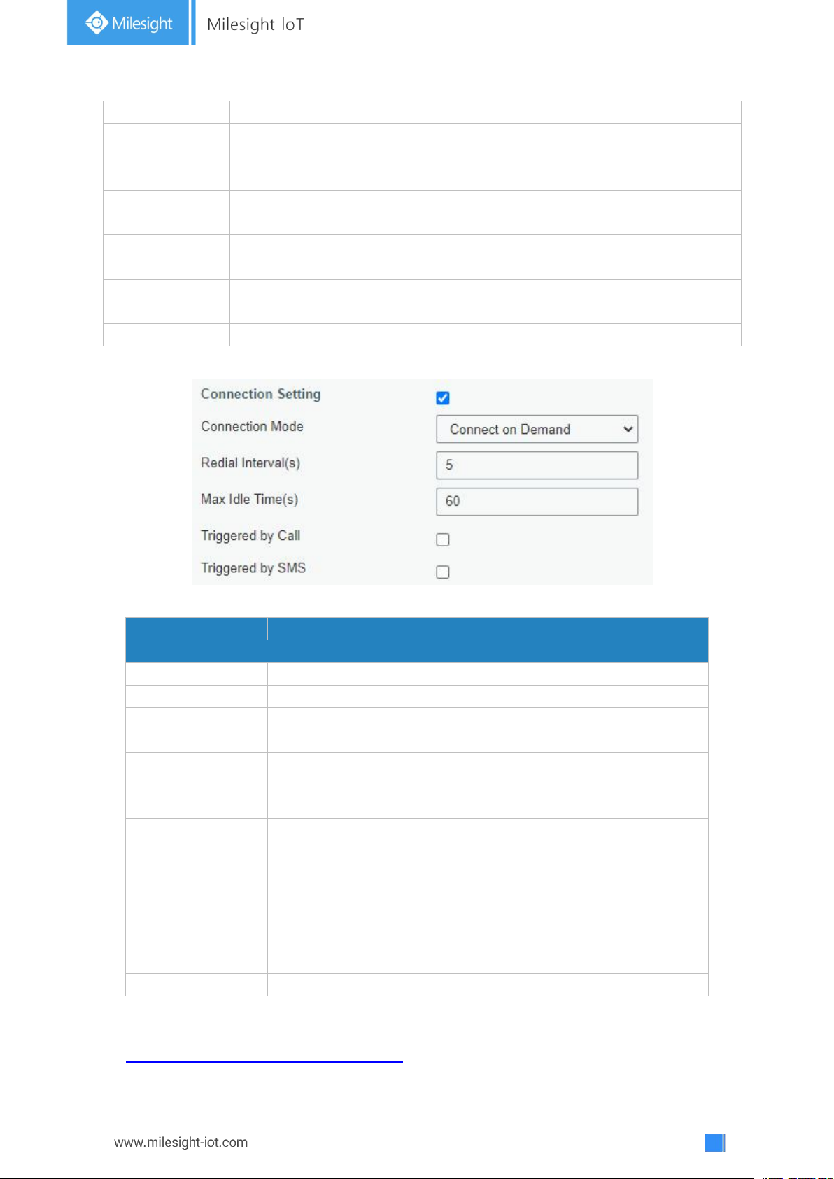
Item
Description
Connection Mode
Connection Mode
Select from "Always Online" and "Connect on Demand".
Redial Interval(s)
Set the time interval between redials. Range: 0-3600.
Max Idle Time(s)
Set the maximum duration of the gateway when current link is
under idle status. Range: 10-3600.
Triggered by Call
The gateway will switch from offline mode to cellular network
mode automatically when it receives a call from the specific
phone number.
Call Group
Select a call group for call trigger. Go to "System > General
Settings > Phone" to set up phone group.
Triggered by SMS
The gateway will switch from offline mode to cellular network
mode automatically when it receives a specific SMS from the
specific mobile phone.
SMS Group
Select a SMS group for trigger. Go to "System > General
Settings > Phone" to set up SMS group.
SMS Text
Fill in the SMS content for triggering.
Figure 3-3-1-10
Table 3-3-1-8 Cellular Parameters
Related Topics
Cellular Connection Application Example
Page 53
53
Phone Group
Loopback
Item
Description
Default
IP Address
Unalterable
127.0.0.1
Netmask
Unalterable
255.0.0.0
Multiple IP
Addresses
Apart from the IP above, user can configure other IP
addresses.
Null
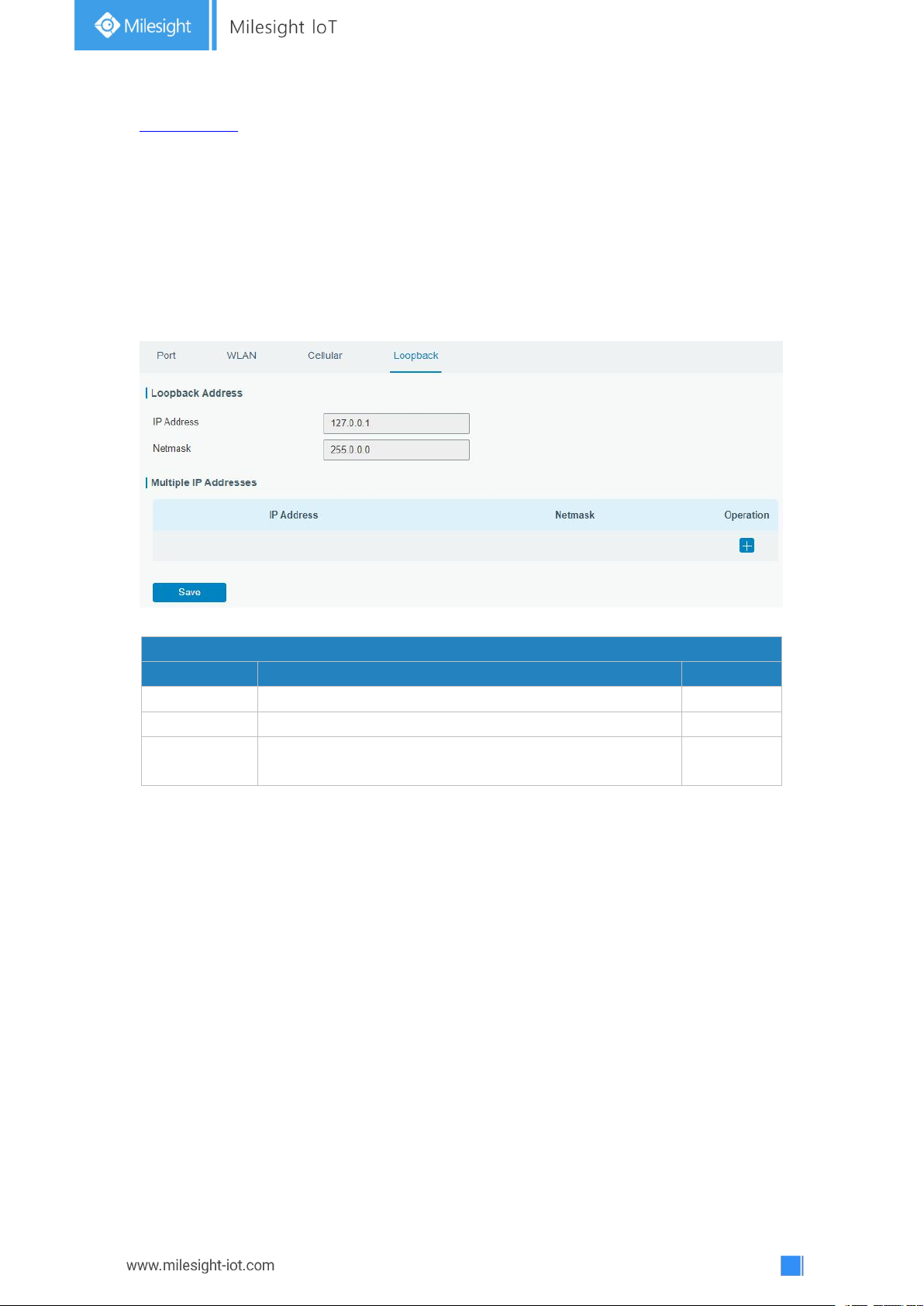
3.3.1.4 Loopback
Loopback interface is used for replacing gateway's ID as long as it is activated. When the
interface is DOWN, the ID of the gateway has to be selected again which leads to long
convergence time of OSPF. Therefore, Loopback interface is generally recommended as
the ID of the gateway.
Loopback interface is a logic and virtual interface on gateway. Under default conditions,
there's no loopback interface on gateway, but it can be created as required.
Figure 3-3-1-11
Table 3-3-1-9 Loopback Parameters
3.3.2 Firewall
This section describes how to set the firewall parameters, including website block, ACL,
DMZ, Port Mapping and MAC Binding.
The firewall implements corresponding control of data flow at entry direction (from
Internet to local area network) and exit direction (from local area network to Internet)
according to the content features of packets, such as protocol style, source/destination IP
address, etc. It ensures that the gateway operate in a safe environment and host in local
area network.
Page 54
54
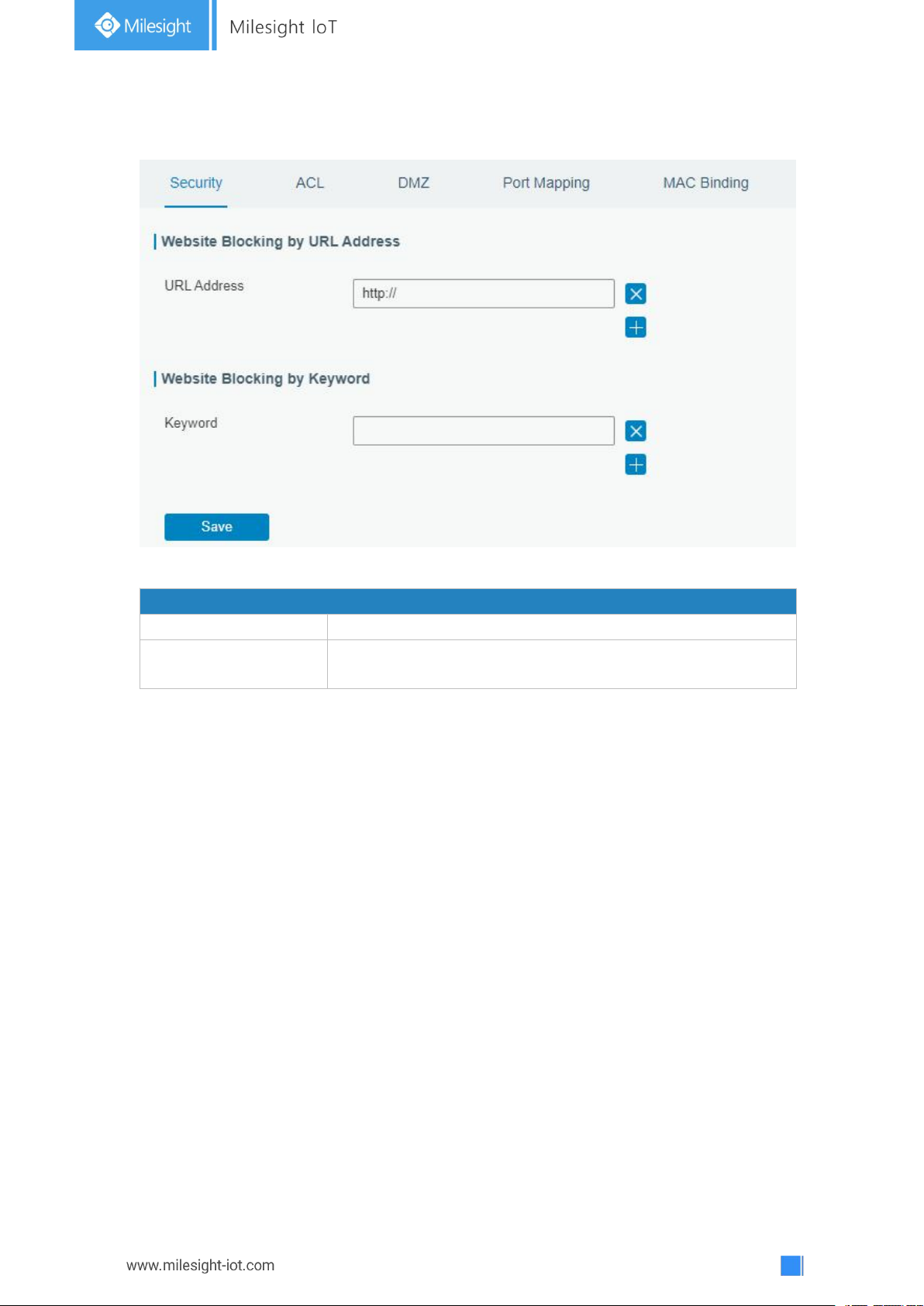
3.3.2.1 Security
Website Blocking
URL Address
Enter the HTTP address which you want to block.
Keyword
You can block specific website by entering keyword. The
maximum number of character allowed is 64.
Figure 3-3-2-1
Table 3-2-2-1 Security Parameters
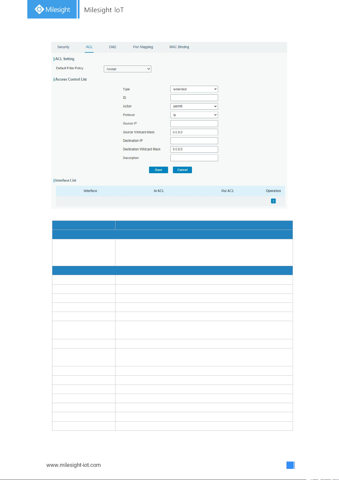
3.3.2.2 ACL
Access control list, also called ACL, implements permission or prohibition of access for
specified network traffic (such as the source IP address) by configuring a series of
matching rules so as to filter the network interface traffic. When gateway receives packet,
the field will be analyzed according to the ACL rule applied to the current interface. After
the special packet is identified, the permission or prohibition of corresponding packet will
be implemented according to preset strategy.
The data package matching rules defined by ACL can also be used by other functions
requiring flow distinction.
Page 55
55
Figure 3-3-2-2
Item
Description
ACL Setting
Default Filter Policy
Select from "Accept" and "Deny".
The packets which are not included in the access control list will
be processed by the default filter policy.
Access Control List
Type
Select type from "Extended" and "Standard".
ID
User-defined ACL number. Range: 1-199.
Action
Select from "Permit" and "Deny".
Protocol
Select protocol from "ip", "icmp", "tcp", "udp", and "1-255".
Source IP
Source network address (leaving it blank means all).
Source Wildcard
Mask
Wildcard mask of the source network address.
Destination IP
Destination network address (0.0.0.0 means all).
Destination Wildcard
Mask
Wildcard mask of destination address.
Description
Fill in a description for the groups with the same ID.
ICMP Type
Enter the type of ICMP packet. Range: 0-255.
ICMP Code
Enter the code of ICMP packet. Range: 0-255.
Source Port Type
Select source port type, such as specified port, port range, etc.
Source Port
Set source port number. Range: 1-65535.
Start Source Port
Set start source port number. Range: 1-65535.
End Source Port
Set end source port number. Range: 1-65535.
Page 56
56
Destination Port
Type
Select destination port type, such as specified port, port range,
etc.
Destination Port
Set destination port number. Range: 1-65535.
Start Destination
Port
Set start destination port number. Range: 1-65535.
End Destination Port
Set end destination port number. Range: 1-65535.
More Details
Show information of the port.
Interface List
Interface
Select network interface for access control.
In ACL
Select a rule for incoming traffic from ACL ID.
Out ACL
Select a rule for outgoing traffic from ACL ID.
Table 3-3-2-2 ACL Parameters
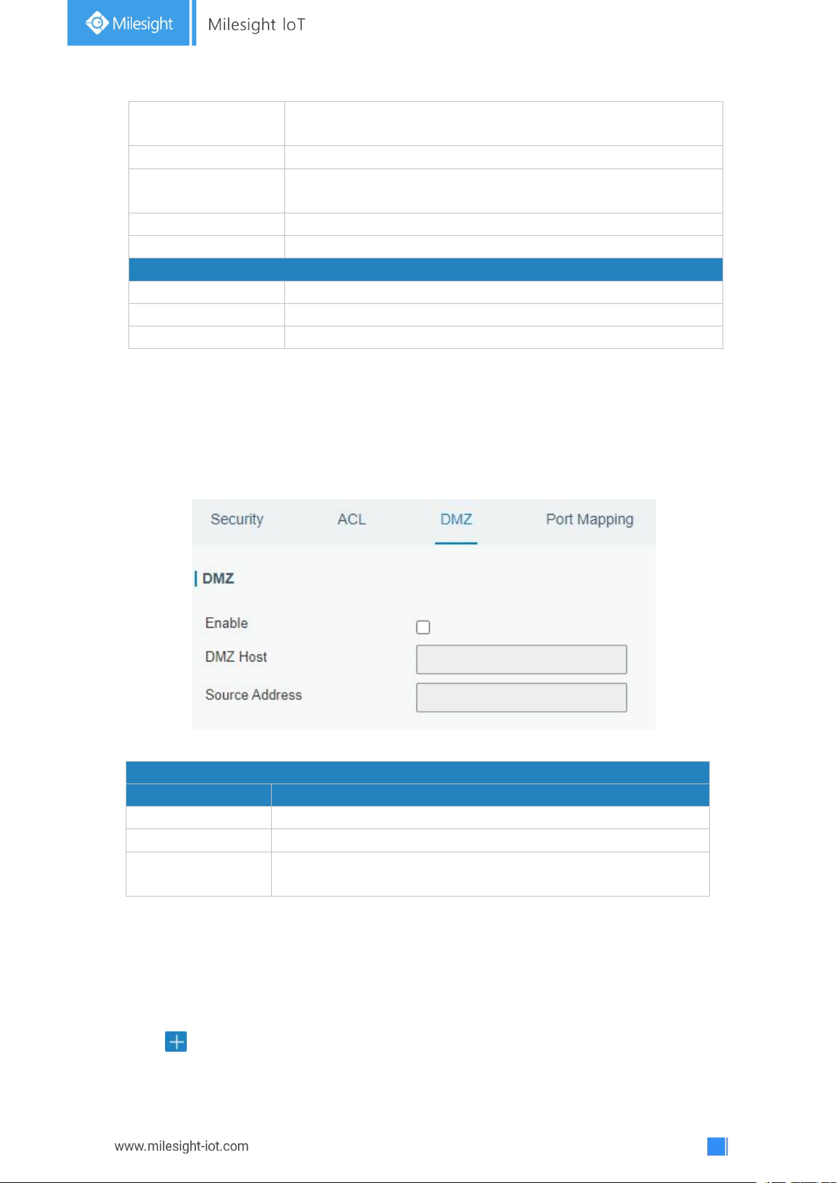
DMZ
Item
Description
Enable
Enable or disable DMZ.
DMZ Host
Enter the IP address of the DMZ host on the internal network.
Source Address
Set the source IP address which can access to DMZ host.
"0.0.0.0/0" means any address.
3.3.2.3 DMZ
DMZ is a host within the internal network that has all ports exposed, except those
forwarded ports in port mapping.
Figure 3-3-2-3
Table 3-3-2-3 DMZ Parameters
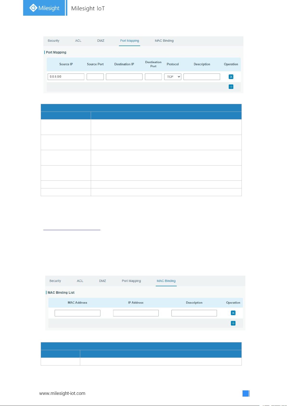
3.3.2.4 Port Mapping
Port mapping is an application of network address translation (NAT) that redirects a
communication request from the combination of an address and port number to another
while the packets are traversing a network gateway such as a gateway or firewall.
Click to add a new port mapping rules.
Page 57
57
Port Mapping
Item
Description
Source IP
Specify the host or network which can access local IP address.
0.0.0.0/0 means all.
Source Port
Enter the TCP or UDP port from which incoming packets are
forwarded. Range: 1-65535.
Destination IP
Enter the IP address that packets are forwarded to after being
received on the incoming interface.
Destination Port
Enter the TCP or UDP port that packets are forwarded to after
being received on the incoming port(s). Range: 1-65535.
Protocol
Select from "TCP" and "UDP" as your application required.
Description
The description of this rule.
Table 3-3-2-4 Port Mapping Parameters
MAC Binding List
Item
Description
MAC Address
Set the binding MAC address.
Related Configuration Example
NAT Application Example
Figure 3-3-2-4
3.3.2.5 MAC Binding
MAC Binding is used for specifying hosts by matching MAC addresses and IP addresses
that are in the list of allowed outer network access.
Figure 3-3-2-5
Page 58
58
IP Address
Set the binding IP address.
Description
Fill in a description for convenience of recording the meaning of the
binding rule for each piece of MAC-IP.
Table 3-3-2-5 MAC Binding Parameters
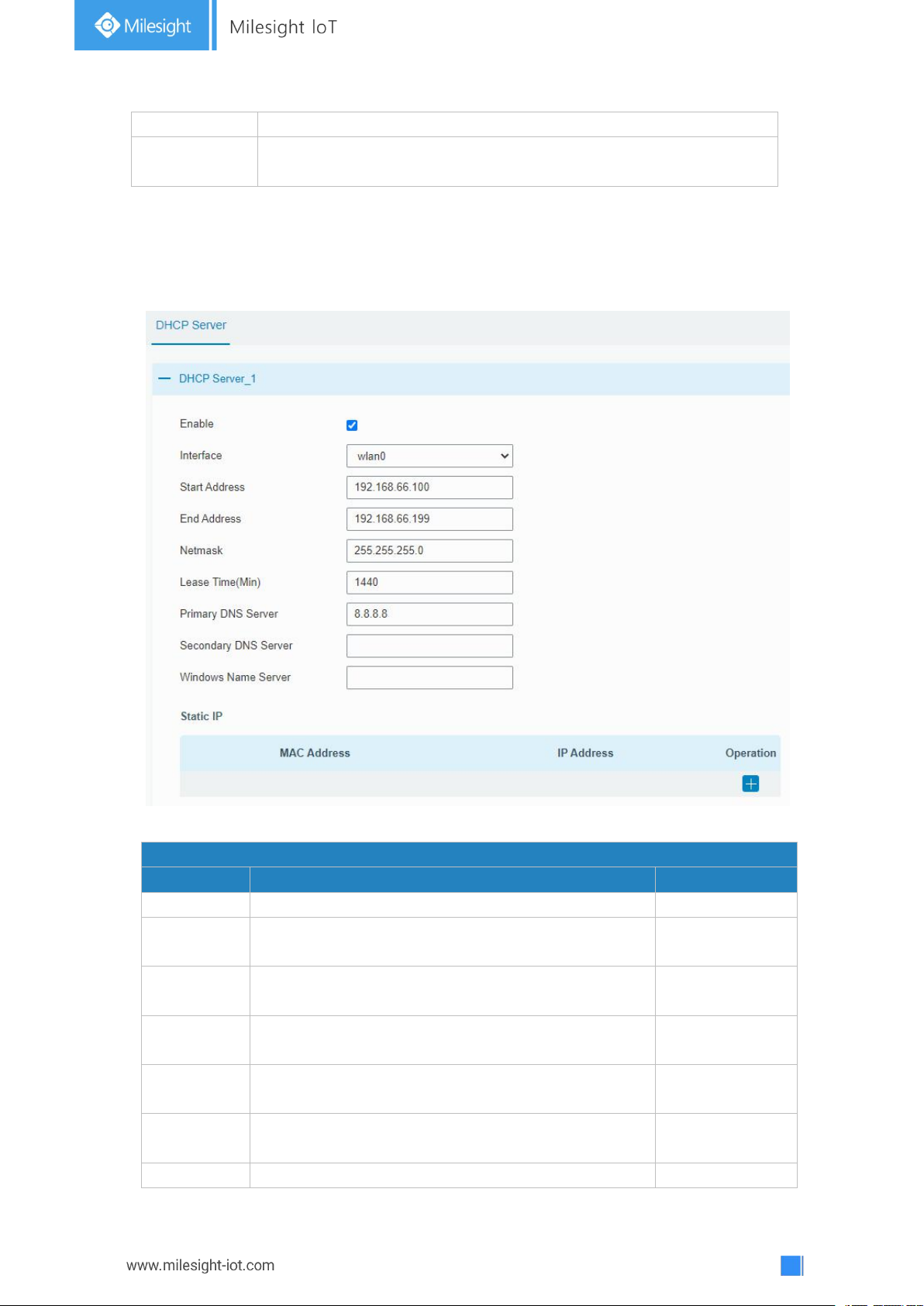
DHCP Server
Item
Description
Default
Enable
Enable or disable DHCP server.
Enable
Interface
Only wlan interface is allowed to distribute IP
addresses.
wlan0
Start
Address
Define the beginning of the pool of IP addresses
which will be leased to DHCP clients.
192.168.1.100
End Address
Define the end of the pool of IP addresses which will
be leased to DHCP clients.
192.168.1.199
Netmask
Define the subnet mask of IP address obtained by
DHCP clients from DHCP server.
255.255.255.0
Lease Time
(Min)
Set the lease time on which the client can use the IP
address obtained from DHCP server. Range: 1-10080.
1440
Primary
Set the primary DNS server.
114.114.114.114
3.3.3 DHCP
UG67 can be set as a DHCP server to distribute IP address when Wi-Fi work as AP mode.
Figure 3-3-3-1
Page 59
59
DNS Server
Secondary
DNS Server
Set the secondary DNS server.
Null
Windows
Name
Server
Define the Windows Internet Naming Service obtained
by DHCP clients from DHCP sever. Generally you can
leave it blank.
Null
Static IP
MAC
Address
Set a static and specific MAC address for the DHCP
client (it should be different from other MACs so as to
avoid conflict).
Null
IP Address
Set a static and specific IP address for the DHCP
client (it should be outside of the DHCP range).
Null
Table 3-3-3-1 DHCP Server Parameters
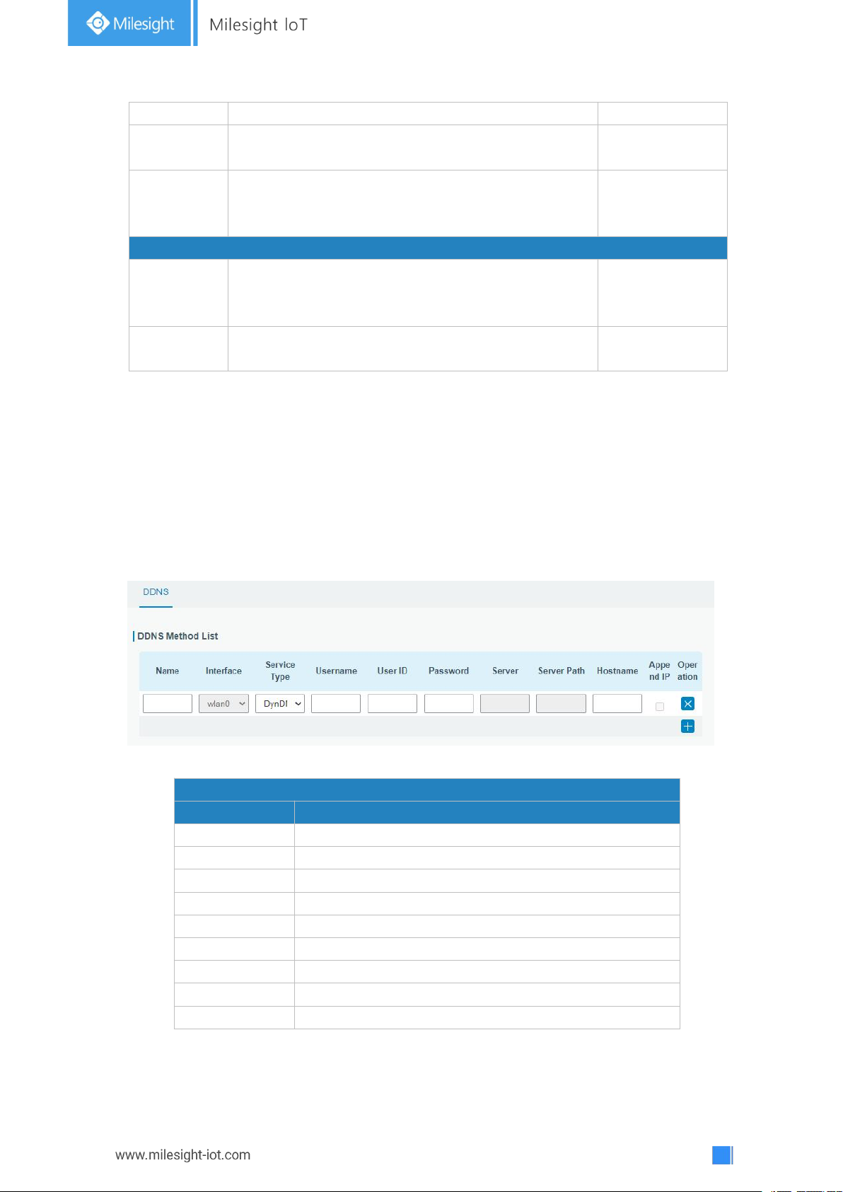
DDNS
Item
Description
Name
Give the DDNS a descriptive name.
Interface
Set interface bundled with the DDNS.
Service Type
Select the DDNS service provider.
Username
Enter the username for DDNS register.
User ID
Enter User ID of the custom DDNS server.
Password
Enter the password for DDNS register.
Server
Enter the name of DDNS server.
Hostname
Enter the hostname for DDNS.
Append IP
Append your current IP to the DDNS server update path.
3.3.4 DDNS
Dynamic DNS (DDNS) is a method that automatically updates a name server in the Domain
Name System, which allows user to alias a dynamic IP address to a static domain name.
DDNS serves as a client tool and needs to coordinate with DDNS server. Before starting
configuration, user shall register on a website of proper domain name provider and apply
for a domain name.
Figure 3-3-4-1
Table 3-3-4-1 DDNS Parameters
Page 60
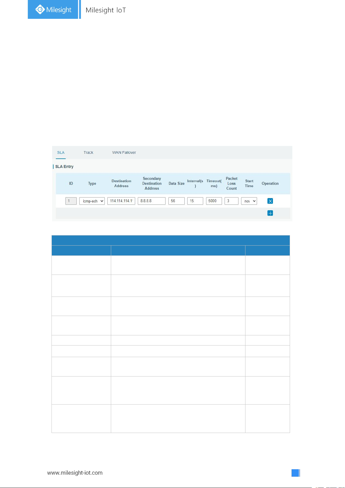
60
3.3.5 Link Failover
SLA
Item
Description
Default
ID
SLA index. Up to 10 SLA settings can be added.
Range: 1-10.
1
Type
ICMP-ECHO is the default type to detect if the
link is alive.
icmp-echo
Destination Address
The detected IP address.
114.114.114.11
4
Secondary
Destination Address
The secondary detected IP address.
8.8.8.8
Data Size
User-defined data size. Range: 0-1000.
56
Interval (s)
User-defined detection interval. Range: 1-608400.
30
Timeout (ms)
User-defined timeout for response to determine
ICMP detection failure. Range: 1-300000.
5000
Packet Loss Count
Define packet loss count in each SLA probe. SLA
probe fails when the preset packet loss count is
exceeded.
5
Start Time
Detection start time; select from "Now" and blank
character. Blank character means this SLA
detection doesn't start.
now
This section describes how to configure link failover strategies, such as VRRP strategies.
Configuration Steps
1. Define one or more SLA operations (ICMP probe).
2. Define one or more track objects to track the status of SLA operation.
3. Define applications associated with track objects, such as VRRP or static routing.
3.3.5.1 SLA
SLA setting is used for configuring link probe method. The default probe type is ICMP.
Figure 3-3-5-1
Table 3-3-5-1 SLA Parameters
Page 61
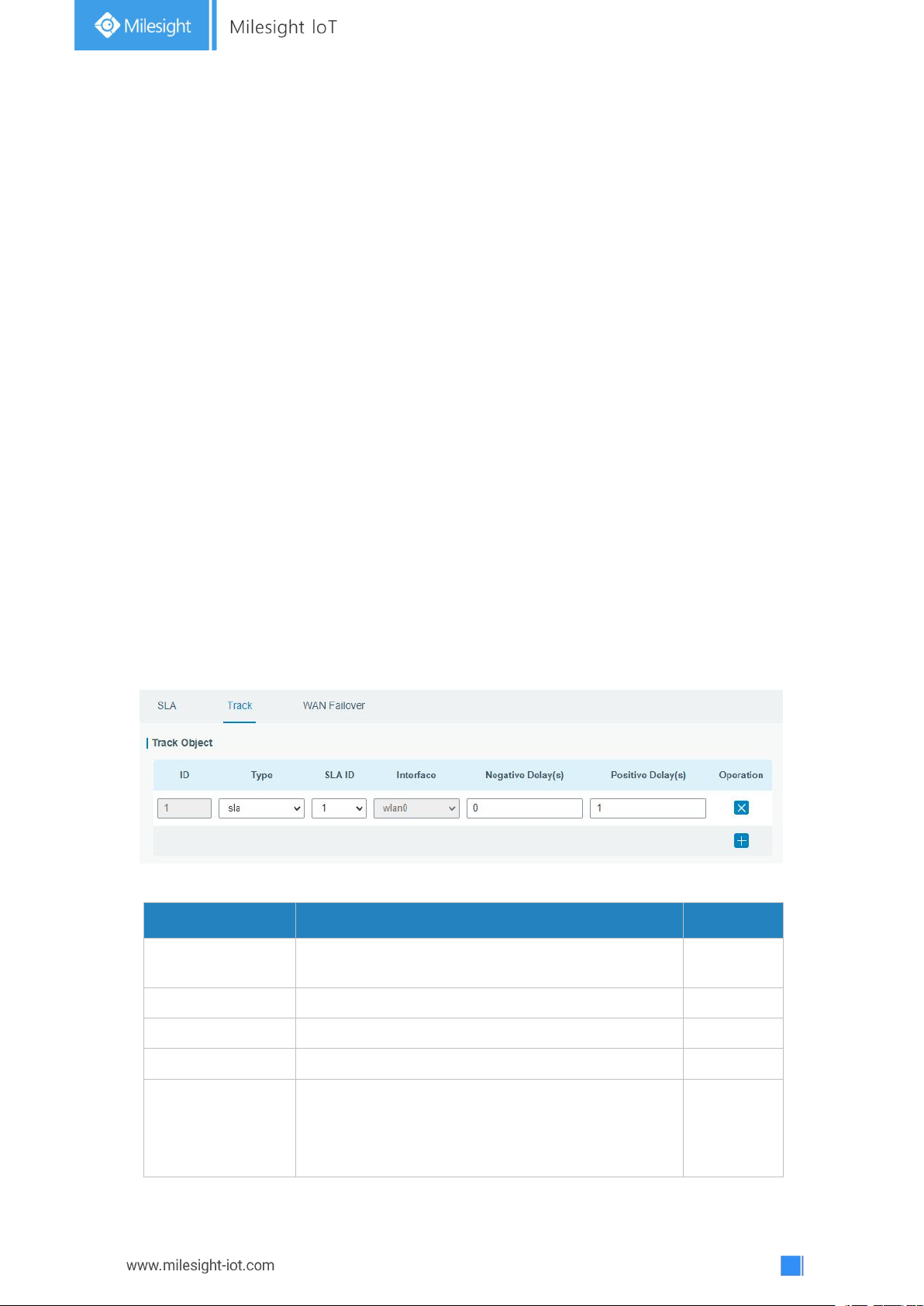
61
3.3.5.2 Track
Item
Description
Default
Index
Track index. Up to 10 track settings can be
configured. Range: 1-10.
1
Type
The options are "sla" and "interface".
SLA
SLA ID
Defined SLA ID.
1
Interface
Select the interface whose status will be detected.
cellular0
Negative Delay (s)
When interface is down or SLA probing fails, it will
wait according to the time set here before actually
changing its status to Down. Range: 0-180 (0 refers
to immediate switching).
0
Track setting is designed for achieving linkage among SLA module, Track module and
Application module. Track setting is located between application module and SLA module
with main function of shielding the differences of various SLA modules and providing
unified interfaces for application module.
Linkage between Track Module and SLA module
Once you complete the configuration, the linkage relationship between Track module and
SLA module will be established. SLA module is used for detection of link status, network
performance and notification of Track module. The detection results help track status
change timely.
- For successful detection, the corresponding track item is Positive.
- For failed detection, the corresponding track item is Negative.
Linkage between Track Module and Application Module
After configuration, the linkage relationship between Track module and Application module
will be established. When any change occurs in track item, a notification that requires
corresponding treatment will be sent to Application module.
Currently, the application modules like VRRP and static routing can get linkage with track
module.
If it sends an instant notification to Application module, the communication may be
interrupted in some circumstances due to routing's failure like timely restoration or other
reasons. Therefore, user can set up a period of time to delay notifying application module
when the track item status changes.
Figure 3-3-5-2
Page 62
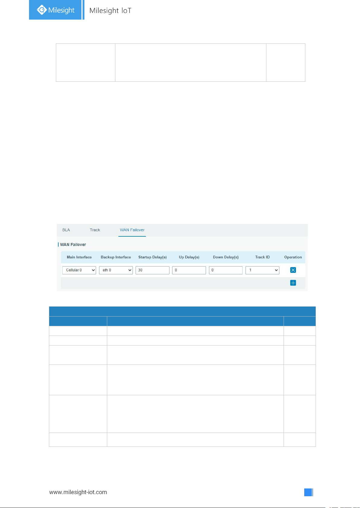
62
Positive Delay (s)
When failure recovery occurs, it will wait according
to the time set here before actually changing its
status to Up. Range: 0-180 (0 refers to immediate
switching).
1
Table 3-3-5-2 Track Parameters
WAN Failover
Parameters
Description
Default
Main Interface
Select a link interface as the main link.
--
Backup Interface
Select a link interface as the backup link.
--
Startup Delay (s)
Set how long to wait for the startup tracking detection policy
to take effect. Range: 0-300.
30
Up Delay (s)
When the primary interface switches from failed detection
to successful detection, switching can be delayed based on
the set time. Range: 0-180 (0 refers to immediate switching)
0
Down Delay (s)
When the primary interface switches from successful
detection to failed detection, switching can be delayed
based on the set time. Range: 0-180 (0 refers to immediate
switching).
0
Track ID
Track detection, select the defined track ID.
--
3.3.5.3 WAN Failover
WAN failover refers to failover between Ethernet WAN interface and cellular interface.
When service transmission can’t be carried out normally due to malfunction of a certain
interface or lack of bandwidth, the rate of flow can be switched to backup interface quickly.
Then the backup interface will carry out service transmission and share network flow so as
to improve reliability of communication of data equipment.
When link state of main interface is switched from up to down, system will have the pre-set
delay works instead of switching to link of backup interface immediately. Only if the state
of main interface is still down after delay, will the system switch to link of backup interface.
Otherwise, system will remain unchanged.
Table 3-3-5-3 WAN Failover Parameters
Figure 3-3-5-3
Page 63
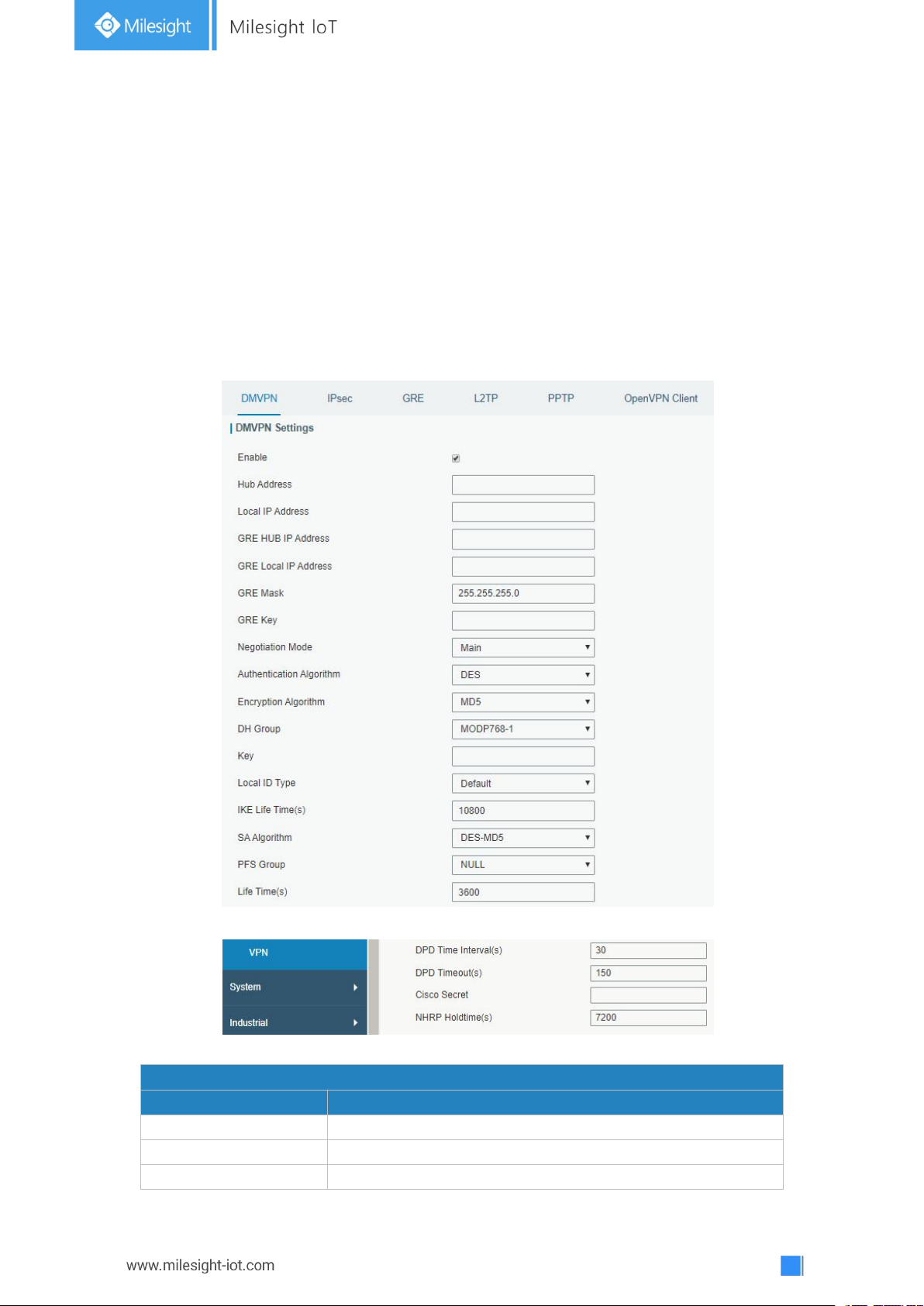
63
3.3.6 VPN
DMVPN
Item
Description
Enable
Enable or disable DMVPN.
Hub Address
The IP address or domain name of DMVPN Hub.
Local IP address
DMVPN local tunnel IP address.
Virtual Private Networks, also called VPNs, are used to securely connect two private
networks together so that devices can connect from one network to the other network via
secure channels.
UG67 supports DMVPN, IPsec, GRE, L2TP, PPTP, OpenVPN, as well as GRE over IPsec and
L2TP over IPsec.
3.3.6.1 DMVPN
A dynamic multi-point virtual private network (DMVPN), combining mGRE and IPsec, is a
secure network that exchanges data between sites without passing traffic through an
organization's headquarter VPN server or gateway.
Figure 3-3-6-1
Figure 3-3-6-2
Page 64

64
GRE Hub IP Address
GRE Hub tunnel IP address.
GRE Local IP Address
GRE local tunnel IP address.
GRE Netmask
GRE local tunnel netmask.
GRE Key
GRE tunnel key.
Negotiation Mode
Select from "Main" and "Aggressive".
Authentication
Algorithm
Select from "DES", "3DES", "AES128", "AES192" and
"AES256".
Encryption Algorithm
Select from "MD5" and "SHA1".
DH Group
Select from "MODP768_1", "MODP1024_2" and
"MODP1536_5".
Key
Enter the preshared key.
Local ID Type
Select from "Default", "ID", "FQDN", and "User FQDN"
IKE Life Time (s)
Set the lifetime in IKE negotiation. Range: 60-86400.
SA Algorithm
Select from "DES_MD5", "DES_SHA1", "3DES_MD5",
"3DES_SHA1", "AES128_MD5", "AES128_SHA1",
"AES192_MD5", "AES192_SHA1", "AES256_MD5" and
"AES256_SHA1".
PFS Group
Select from "NULL", "MODP768_1", "MODP1024_2" and
"MODP1536-5".
Life Time (s)
Set the lifetime of IPsec SA. Range: 60-86400.
DPD Interval Time (s)
Set DPD interval time
DPD Timeout (s)
Set DPD timeout.
Cisco Secret
Cisco Nhrp key.
NHRP Holdtime (s)
The holdtime of Nhrp protocol.
Table 3-3-6-1 DMVPN Parameters
3.3.6.2 IPSec
IPsec is especially useful for implementing virtual private networks and for remote user
access through dial-up connection to private networks. A big advantage of IPsec is that
security arrangements can be handled without requiring changes to individual user
computers.
IPsec provides three choices of security service: Authentication Header (AH),
Encapsulating Security Payload (ESP), and Internet Key Exchange (IKE). AH essentially
allows authentication of the senders’ data. ESP supports both authentication of the sender
and data encryption. IKE is used for cipher code exchange. All of them can protect one and
more data flows between hosts, between host and gateway, and between gateways.
Page 65
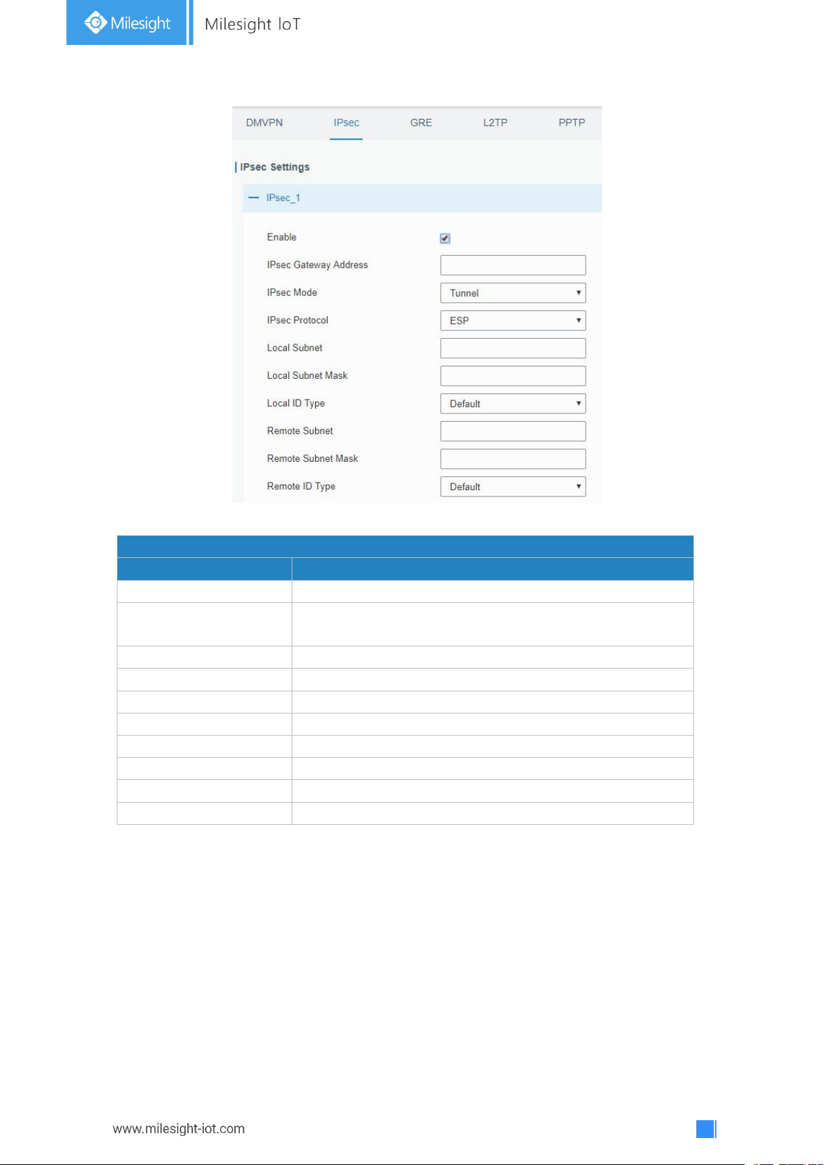
65
Figure 3-3-6-3
IPsec
Item
Description
Enable
Enable IPsec tunnel. A maximum of 3 tunnels is allowed.
IPsec Gateway Address
Enter the IP address or domain name of remote IPsec
server.
IPsec Mode
Select from "Tunnel" and "Transport".
IPsec Protocol
Select from "ESP" and "AH".
Local Subnet
Enter the local subnet IP address that IPsec protects.
Local Subnet Netmask
Enter the local netmask that IPsec protects.
Local ID Type
Select from "Default", "ID", "FQDN", and "User FQDN".
Remote Subnet
Enter the remote subnet IP address that IPsec protects.
Remote Subnet Mask
Enter the remote netmask that IPsec protects.
Remote ID type
Select from "Default", "ID", "FQDN", and "User FQDN".
Table 3-3-6-2 IPsec Parameters
Page 66
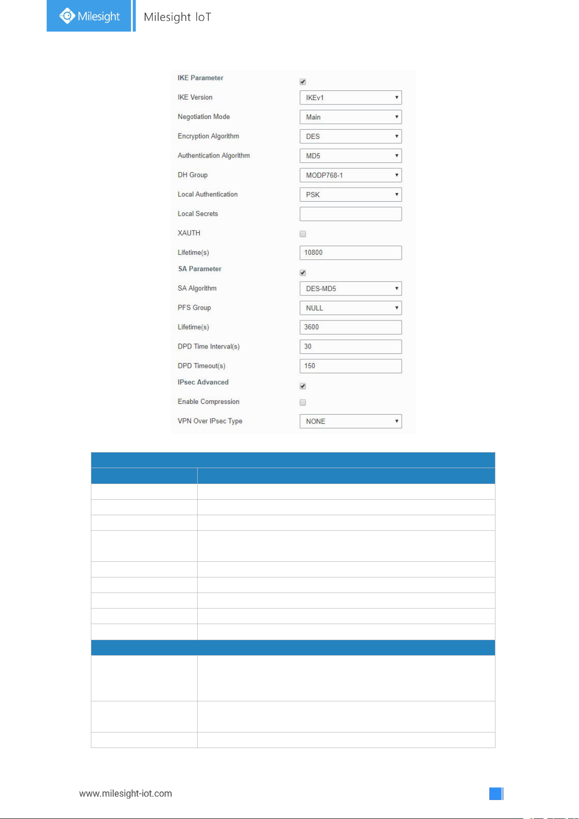
66
Figure 3-3-6-4
IKE Parameter
Item
Description
IKE Version
Select from "IKEv1" and "IKEv2".
Negotiation Mode
Select from "Main" and "Aggressive".
Encryption Algorithm
Select from "DES", "3DES", "AES128", "AES192" and "AES256".
Authentication
Algorithm
Select from "MD5" and " SHA1"
DH Group
Select from "MODP768_1", "MODP1024_2" and "MODP1536_5".
Local Authentication
Select from "PSK" and "CA".
Local Secrets
Enter the preshared key.
XAUTH
Enter XAUTH username and password after XAUTH is enabled.
Lifetime (s)
Set the lifetime in IKE negotiation. Range: 60-86400.
SA Parameter
SA Algorithm
Select from "DES_MD5", "DES_SHA1", "3DES_MD5",
"3DES_SHA1", "AES128_MD5", "AES128_SHA1", "AES192_MD5",
"AES192_SHA1", "AES256_MD5" and "AES256_SHA1".
PFS Group
Select from "NULL", "MODP768_1" , "MODP1024_2" and
"MODP1536_5".
Lifetime (s)
Set the lifetime of IPsec SA. Range: 60-86400.
Page 67
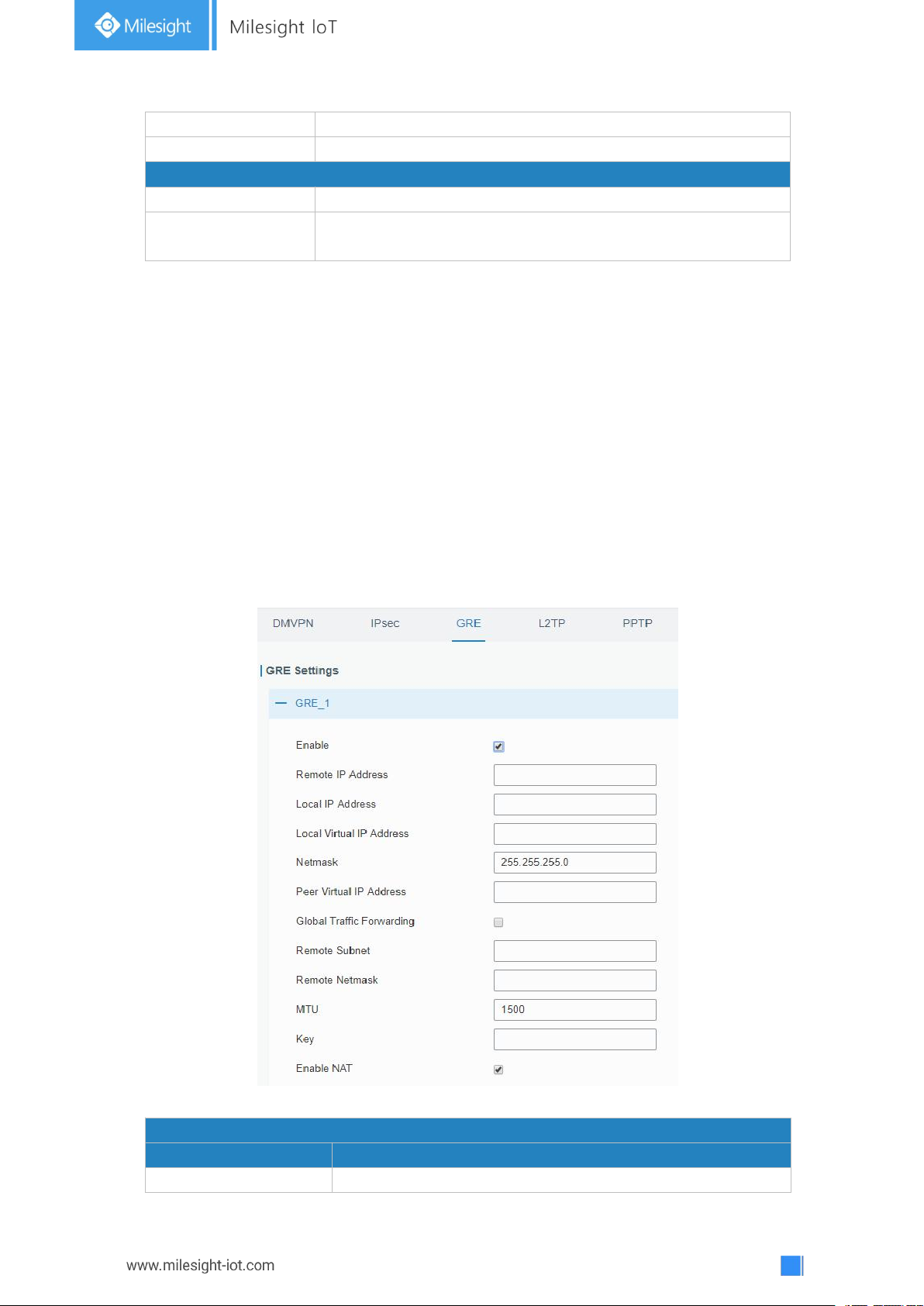
67
DPD Interval Time(s)
Set DPD interval time to detect if the remote side fails.
DPD Timeout(s)
Set DPD timeout. Range: 10-3600.
IPsec Advanced
Enable Compression
The head of IP packet will be compressed after it's enabled.
VPN Over IPsec Type
Select from "NONE", "GRE" and "L2TP" to enable VPN over
IPsec function.
Table 3-3-6-3 IPsec Parameters
GRE
Item
Description
Enable
Check to enable GRE function.
3.3.6.3 GRE
Generic Routing Encapsulation (GRE) is a protocol that encapsulates packets in order to
route other protocols over IP networks. It’s a tunneling technology that provides a channel
through which encapsulated data message can be transmitted and encapsulation and
decapsulation can be realized at both ends.
In the following circumstances the GRE tunnel transmission can be applied:
- GRE tunnel can transmit multicast data packets as if it were a true network interface.
Single use of IPSec cannot achieve the encryption of multicast.
- A certain protocol adopted cannot be routed.
- A network of different IP addresses shall be required to connect other two similar
networks.
Figure 3-3-6-5
Page 68
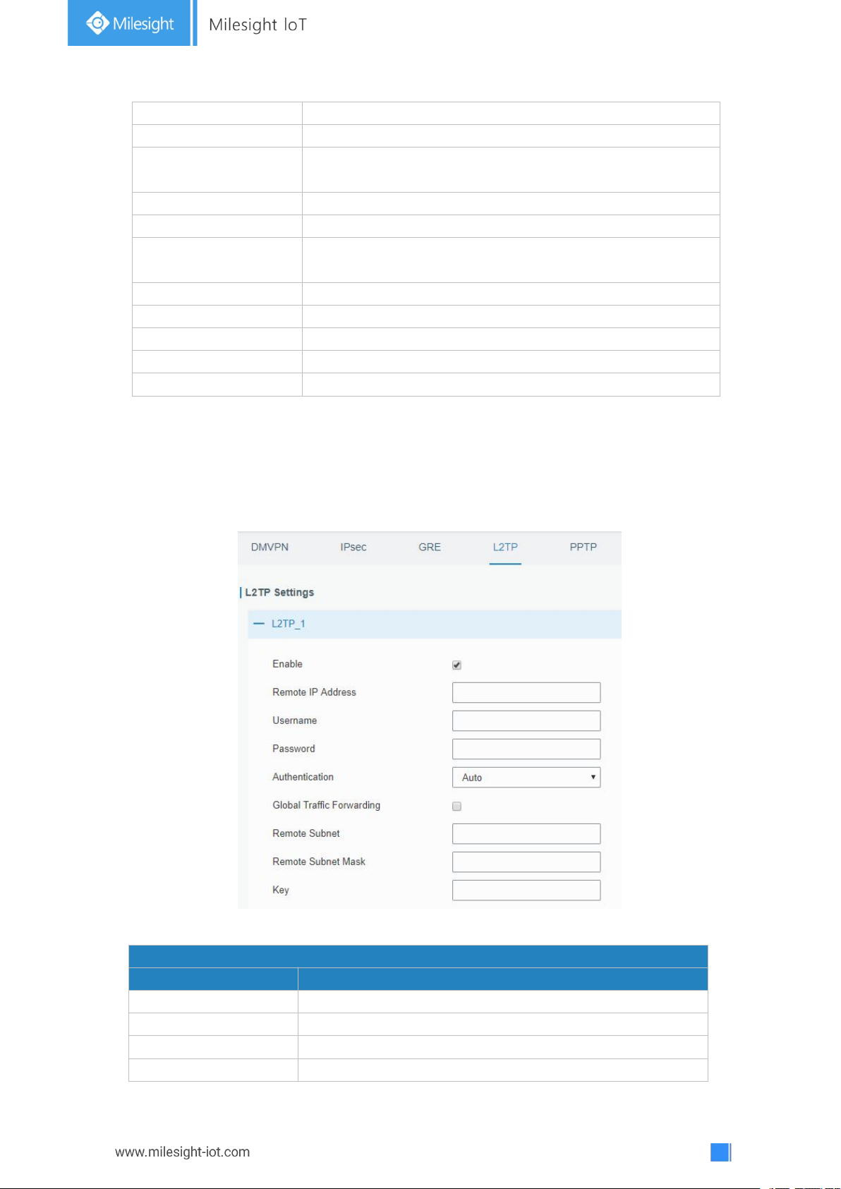
68
Remote IP Address
Enter the real remote IP address of GRE tunnel.
Local IP Address
Set the local IP address.
Local Virtual IP
Address
Set the local tunnel IP address of GRE tunnel.
Netmask
Set the local netmask.
Peer Virtual IP Address
Enter remote tunnel IP address of GRE tunnel.
Global Traffic
Forwarding
All the data traffic will be sent out via GRE tunnel when this
function is enabled.
Remote Subnet
Enter the remote subnet IP address of GRE tunnel.
Remote Netmask
Enter the remote netmask of GRE tunnel.
MTU
Enter the maximum transmission unit. Range: 64-1500.
Key
Set GRE tunnel key.
Enable NAT
Enable NAT traversal function.
Table 3-3-6-4 GRE Parameters
L2TP
Item
Description
Enable
Check to enable L2TP function.
Remote IP Address
Enter the public IP address or domain name of L2TP server.
Username
Enter the username that L2TP server provides.
Password
Enter the password that L2TP server provides.
3.3.6.4 L2TP
Layer Two Tunneling Protocol (L2TP) is an extension of the Point-to-Point Tunneling
Protocol (PPTP) used by an Internet service provider (ISP) to enable the operation of a
virtual private network (VPN) over the Internet.
Figure 3-3-6-6
Page 69
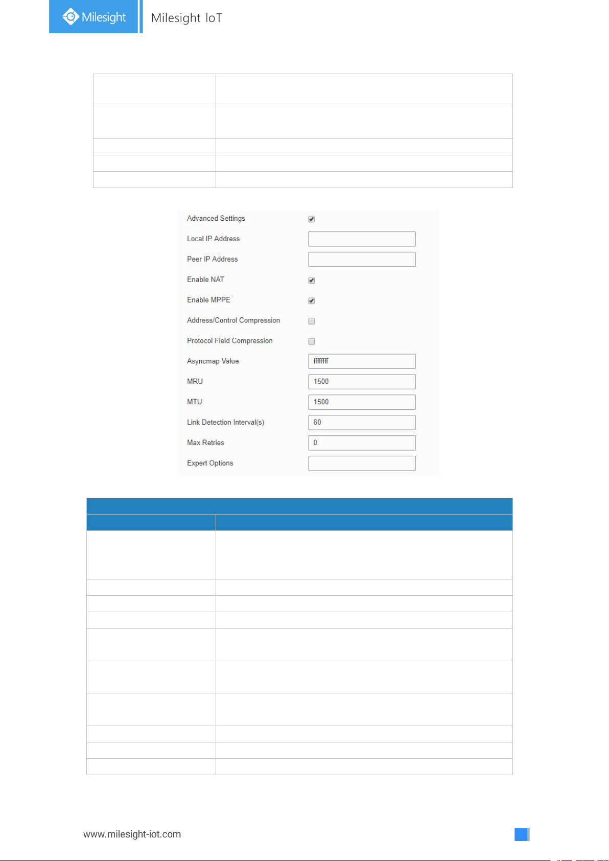
69
Authentication
Select from "Auto", "PAP", "CHAP", "MS-CHAPv1" and
"MS-CHAPv2".
Global Traffic
Forwarding
All of the data traffic will be sent out via L2TP tunnel after
this function is enabled.
Remote Subnet
Enter the remote IP address that L2TP protects.
Remote Subnet Mask
Enter the remote netmask that L2TP protects.
Key
Enter the password of L2TP tunnel.
Table 3-3-6-5 L2TP Parameters
Advanced Settings
Item
Description
Local IP Address
Set tunnel IP address of L2TP client. Client will obtain
tunnel IP address automatically from the server when it's
null.
Peer IP Address
Enter tunnel IP address of L2TP server.
Enable NAT
Enable NAT traversal function.
Enable MPPE
Enable MPPE encryption.
Address/Control
Compression
For PPP initialization. User can keep the default option.
Protocol Field
Compression
For PPP initialization. User can keep the default option.
Asyncmap Value
One of the PPP protocol initialization strings. User can keep
the default value. Range: 0-ffffffff.
MRU
Set the maximum receive unit. Range: 64-1500.
MTU
Set the maximum transmission unit. Range: 64-1500
Link Detection Interval
Set the link detection interval time to ensure tunnel
Figure 3-3-6-7
Page 70
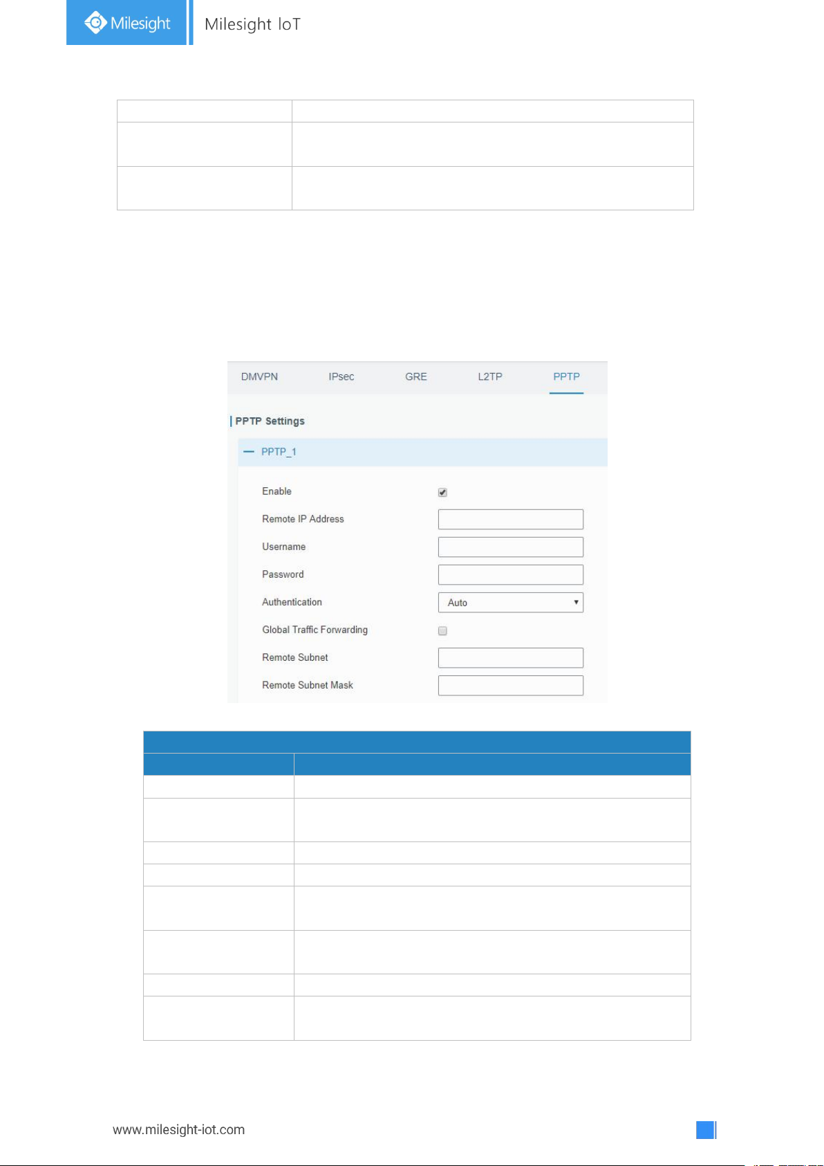
70
(s)
connection. Range: 0-600.
Max Retries
Set the maximum times of retry to detect the L2TP
connection failure. Range: 0-10.
Expert Options
User can enter some other PPP initialization strings in this
field and separate the strings with blank space.
Table 3-3-6-6 L2TP Parameters
PPTP
Item
Description
Enable
Enable PPTP client. A maximum of 3 tunnels is allowed.
Remote IP Address
Enter the public IP address or domain name of PPTP
server.
Username
Enter the username that PPTP server provides.
Password
Enter the password that PPTP server provides.
Authentication
Select from "Auto", "PAP", "CHAP", "MS-CHAPv1", and
"MS-CHAPv2".
Global Traffic
Forwarding
All of the data traffic will be sent out via PPTP tunnel once
enable this function.
Remote Subnet
Set the peer subnet of PPTP.
Remote Subnet
Mask
Set the netmask of peer PPTP server.
3.3.6.5 PPTP
Point-to-Point Tunneling Protocol (PPTP) is a protocol that allows corporations to extend
their own corporate network through private "tunnels" over the public Internet. Effectively, a
corporation uses a wide-area network as a single large local area network.
Figure 3-3-6-8
Table 3-3-6-7 PPTP Parameters
Page 71
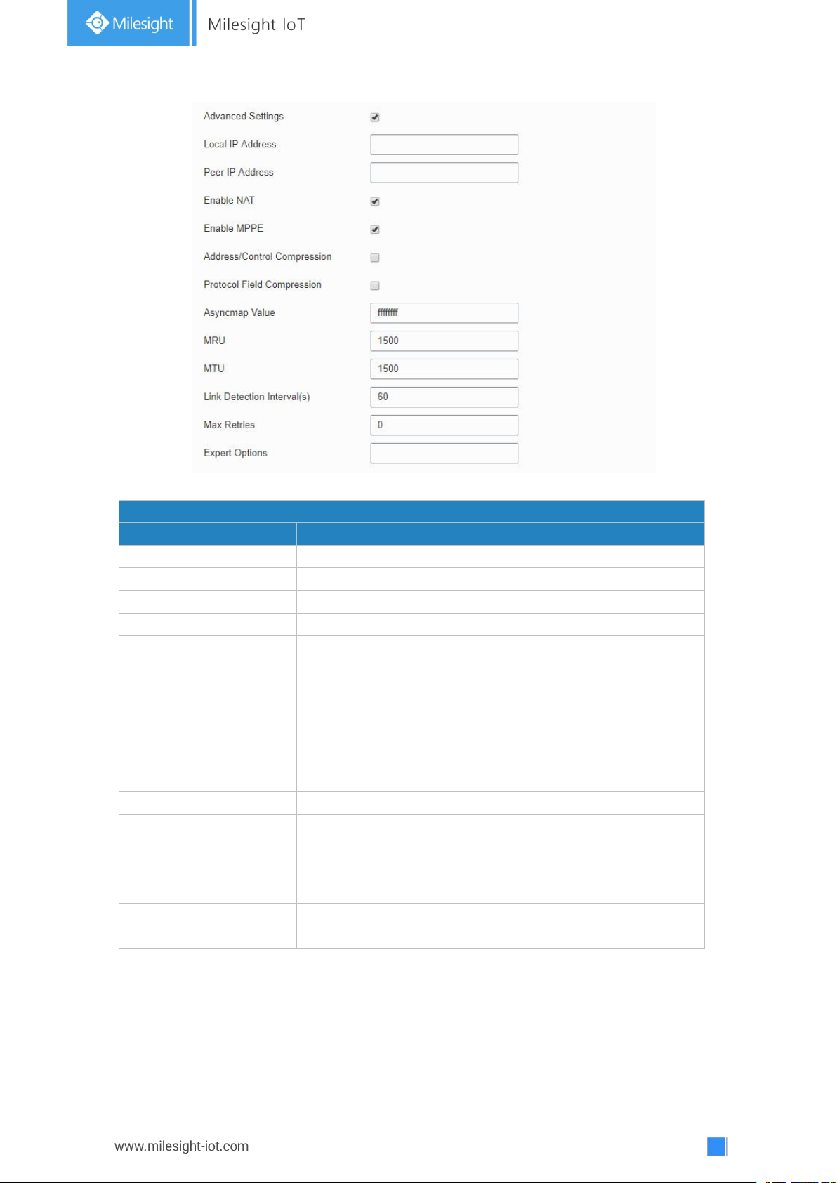
71
Figure 3-3-6-9
PPTP Advanced Settings
Item
Description
Local IP Address
Set IP address of PPTP client.
Peer IP Address
Enter tunnel IP address of PPTP server.
Enable NAT
Enable the NAT faction of PPTP.
Enable MPPE
Enable MPPE encryption.
Address/Control
Compression
For PPP initialization. User can keep the default option.
Protocol Field
Compression
For PPP initialization. User can keep the default option.
Asyncmap Value
One of the PPP protocol initialization strings. User can keep
the default value. Range: 0-ffffffff.
MRU
Enter the maximum receive unit. Range: 0-1500.
MTU
Enter the maximum transmission unit. Range: 0-1500.
Link Detection Interval
(s)
Set the link detection interval time to ensure tunnel
connection. Range: 0-600.
Max Retries
Set the maximum times of retrying to detect the PPTP
connection failure. Range: 0-10.
Expert Options
User can enter some other PPP initialization strings in this
field and separate the strings with blank space.
Table 3-3-6-8 PPTP Parameters
Page 72
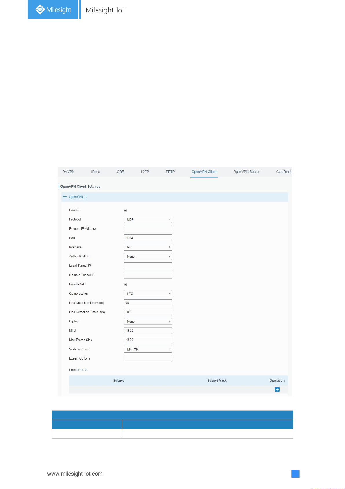
72
3.3.6.6 OpenVPN Client
OpenVPN Client
Item
Description
Enable
Enable OpenVPN client. A maximum of 3 tunnels is allowed.
OpenVPN is an open source virtual private network (VPN) product that offers a simplified
security framework, modular network design, and cross-platform portability.
Advantages of OpenVPN include:
- Security provisions that function against both active and passive attacks.
- Compatibility with all major operating systems.
- High speed (1.4 megabytes per second typically).
- Ability to configure multiple servers to handle numerous connections simultaneously.
- All encryption and authentication features of the OpenSSL library.
- Advanced bandwidth management.
- A variety of tunneling options.
- Compatibility with smart cards that support the Windows Crypt application program
interface (API).
Figure 3-3-6-10
Page 73

73
Protocol
Select from "UDP" and "TCP".
Remote IP Address
Enter remote OpenVPN server's IP address or domain name.
Port
Enter the listening port number of remote OpenVPN server.
Range: 1-65535.
Interface
Select from "tun" and "tap".
Authentication
Select from "None", "Pre-shared", "Username/Password",
"X.509 cert", and "X.509 cert+user".
Local Tunnel IP
Set local tunnel address.
Remote Tunnel IP
Enter remote tunnel address.
Global Traffic
Forwarding
All the data traffic will be sent out via OpenVPN tunnel when
this function is enabled.
Enable TLS
Authentication
Check to enable TLS authentication.
Username
Enter username provided by OpenVPN server.
Password
Enter password provided by OpenVPN server.
Enable NAT
Enable NAT traversal function.
Compression
Select LZO to compress data.
Link Detection Interval
(s)
Set link detection interval time to ensure tunnel connection.
Range: 10-1800.
Link Detection Timeout
(s)
Set link detection timeout. OpenVPN will be reestablished
after timeout. Range: 60-3600.
Cipher
Select from "NONE", "BF-CBC", "DE-CBC", "DES-EDE3-CBC",
"AES-128-CBC", "AES-192-CBC" and "AES-256-CBC".
MTU
Enter the maximum transmission unit. Range: 128-1500.
Max Frame Size
Set the maximum frame size. Range: 128-1500.
Verbose Level
Select from "ERROR", "WARING", "NOTICE" and "DEBUG".
Expert Options
User can enter some other PPP initialization strings in this
field and separate the strings with blank space.
Local Route
Subnet
Set the local route's IP address.
Subnet Mask
Set the local route's netmask.
Table 3-3-6-9 OpenVPN Client Parameters
3.3.6.7 OpenVPN Server
UG67 supports OpenVPN server to create secure point-to-point or site-to-site connections
in routed or bridged configurations and remote access facilities.
Page 74
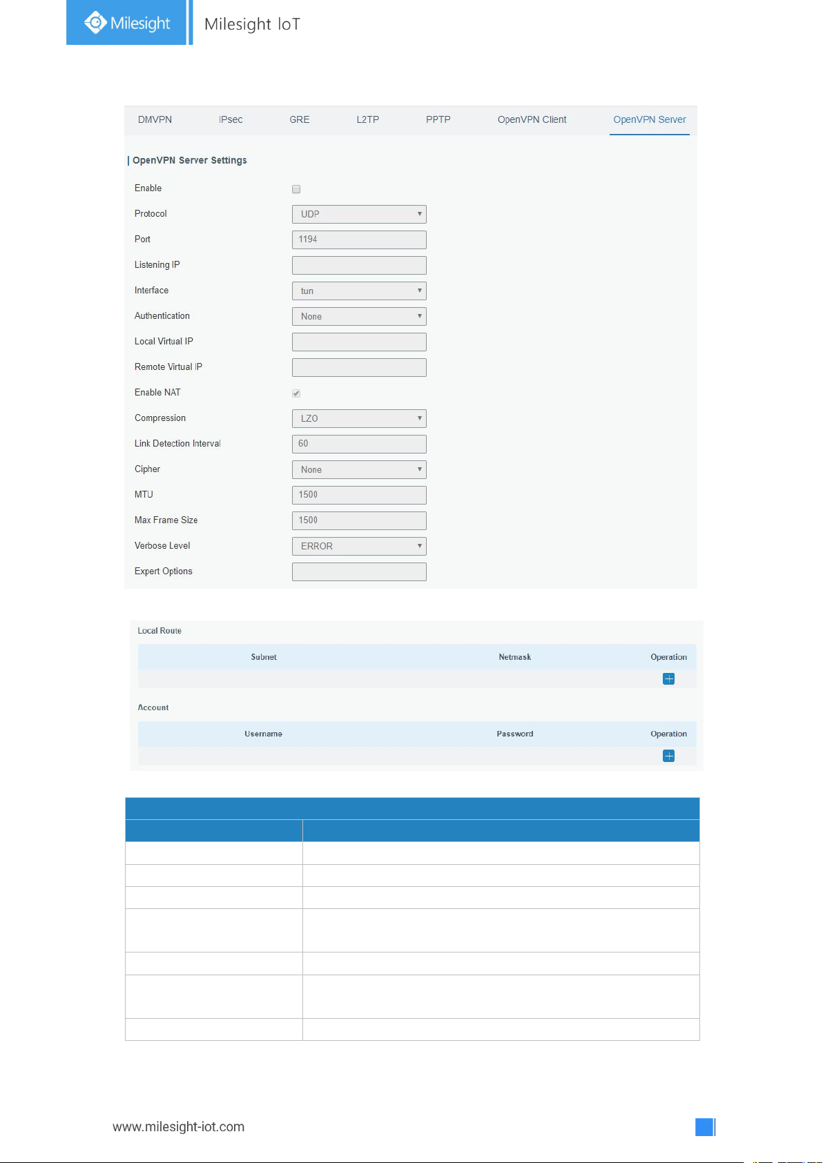
74
Figure 3-3-6-11
OpenVPN Server
Item
Description
Enable
Enable/disable OpenVPN server.
Protocol
Select from TCP and UDP.
Port
Fill in listening port number. Range: 1-65535.
Listening IP
Enter WAN IP address or LAN IP address. Leaving it blank
refers to all active WAN IP and LAN IP address.
Interface
Select from " tun" and "tap".
Authentication
Select from "None", "Pre-shared", "Username/Password",
"X.509 cert" and "X. 509 cert +user".
Local Virtual IP
The local tunnel address of OpenVPN's tunnel.
Figure 3-3-6-12
Page 75
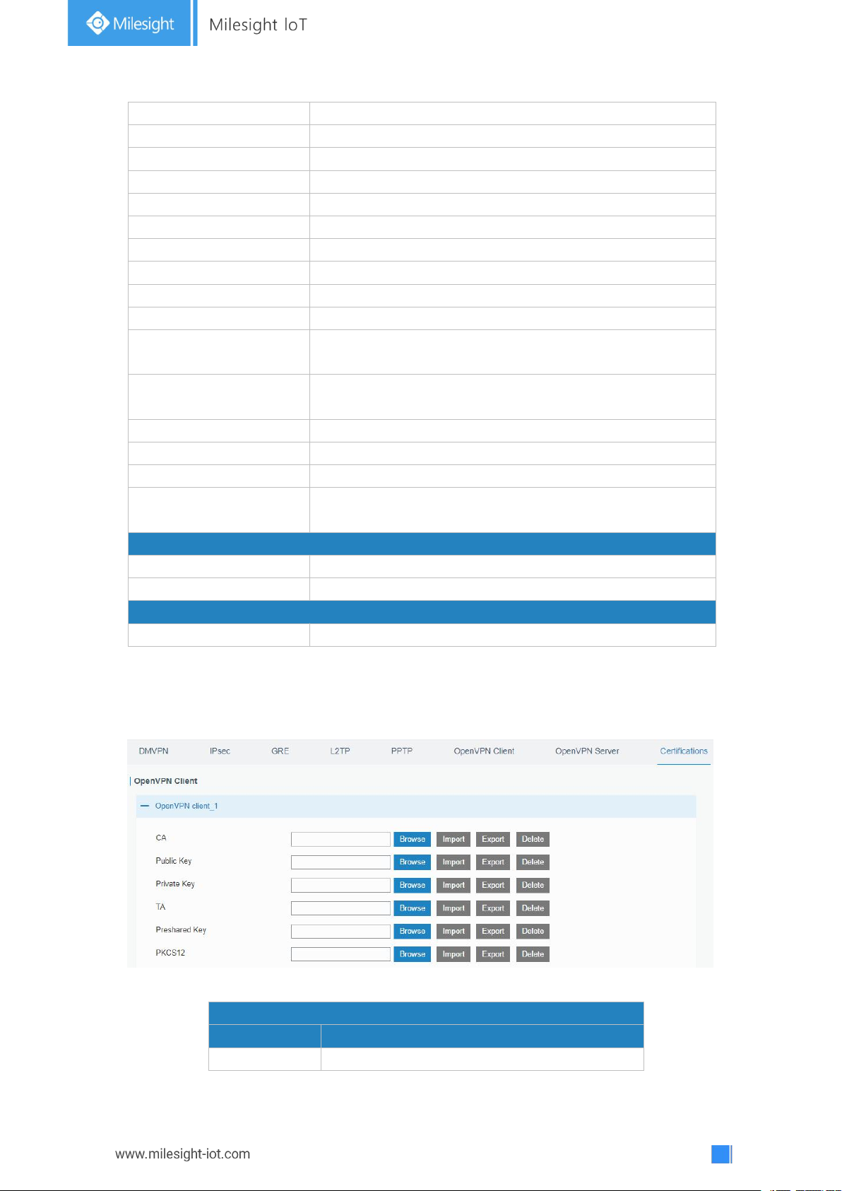
75
Remote Virtual IP
The remote tunnel address of OpenVPN's tunnel.
Client Subnet
Local subnet IP address of OpenVPN client.
Client Netmask
Local netmask of OpenVPN client.
Renegotiation Interval(s)
Set interval for renegotiation. Range: 0-86400.
Max Clients
Maximum OpenVPN client number. Range: 1-128.
Enable CRL
Enable CRL
Enable Client to Client
Allow access between different OpenVPN clients.
Enable Dup Client
Allow multiple users to use the same certification.
Enable NAT
Check to enable the NAT traversal function.
Compression
Select "LZO" to compress data.
Link Detection Interval
Set link detection interval time to ensure tunnel connection.
Range: 10-1800.
Cipher
Select from "NONE", "BF-CBC", "DES-CBC", "DES-EDE3-CBC",
"AES-128-CBC", "AES-192-CBC" and "AES-256-CBC".
MTU
Enter the maximum transmission unit. Range: 64-1500.
Max Frame Size
Set the maximum frame size. Range: 64-1500.
Verbose Level
Select from "ERROR", "WARING", "NOTICE" and "DEBUG".
Expert Options
User can enter some other PPP initialization strings in this
field and separate the strings with blank space.
Local Route
Subnet
The real local IP address of OpenVPN client.
Netmask
The real local netmask of OpenVPN client.
Account
Username & Password
Set username and password for OpenVPN client.
Table 3-3-6-10 OpenVPN Server Parameters
OpenVPN Client
Item
Description
CA
Import/Export CA certificate file.
3.3.6.8 Certifications
User can import/export certificate and key files for OpenVPN and IPsec on this page.
Figure 3-3-6-13
Page 76
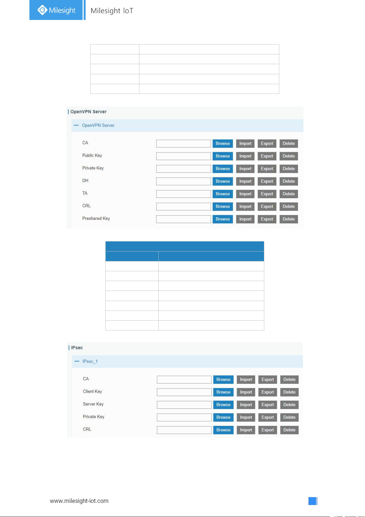
76
Public Key
Import/Export public key file.
Private Key
Import/Export private key file.
TA
Import/Export TA key file.
Preshared Key
Import/Export static key file.
PKCS12
Import/Export PKCS12 certificate file.
Table 3-3-6-11 OpenVPN Client Certification Parameters
OpenVPN Server
Item
Description
CA
Import/Export CA certificate file.
Public Key
Import/Export public key file.
Private Key
Import/Export private key file.
DH
Import/Export DH key file.
TA
Import/Export TA key file.
CRL
Import/Export CRL.
Preshared Key
Import/Export static key file.
Figure 3-3-6-14
Table 3-3-6-12 OpenVPN Server Parameters
Figure 3-3-6-15
Page 77
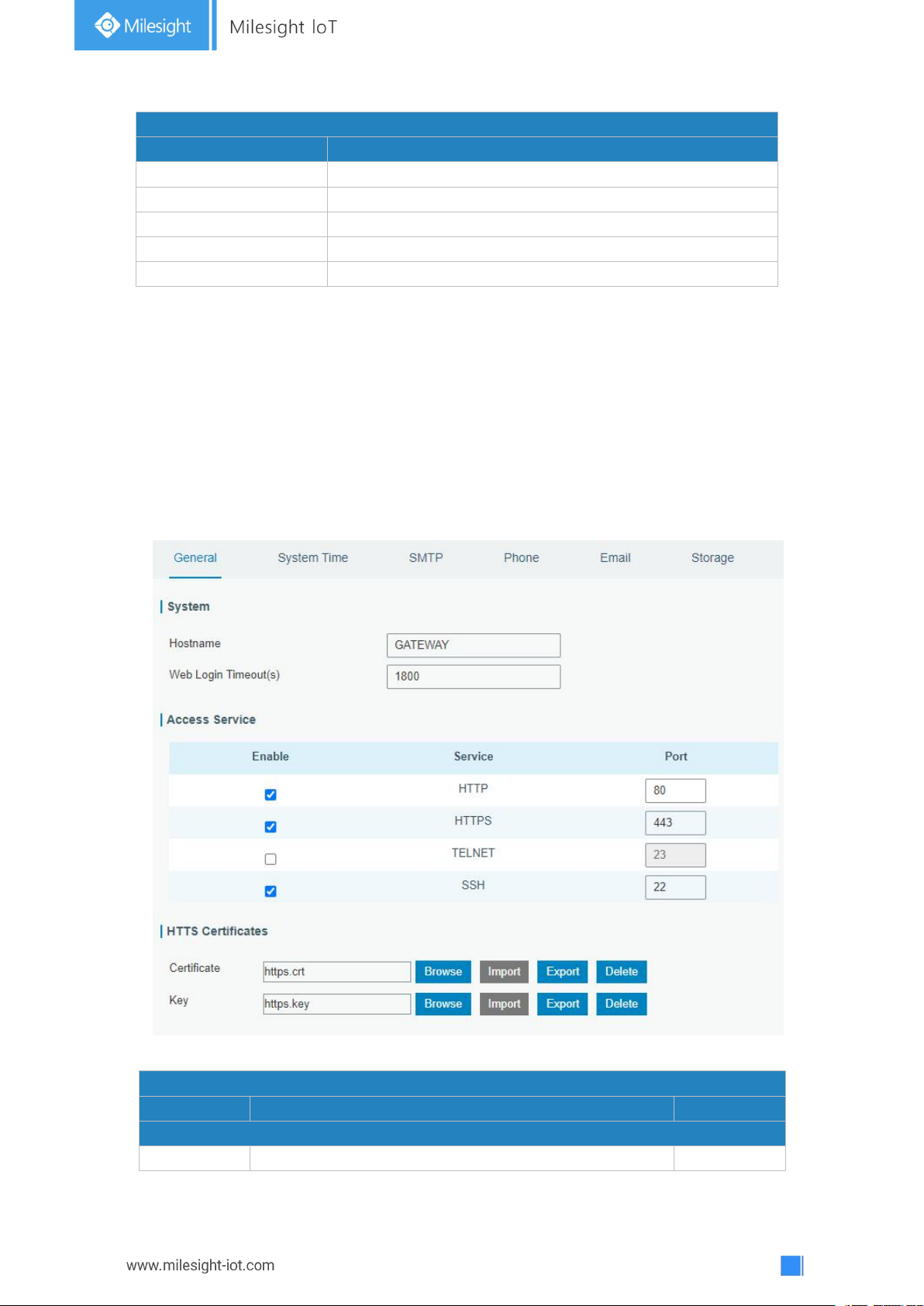
77
IPsec
Item
Description
CA
Import/Export CA certificate.
Client Key
Import/Export client key.
Server Key
Import/Export server key.
Private Key
Import/Export private key.
CRL
Import/Export certificate recovery list.
Table 3-3-6-13 IPsec Parameters
General
Item
Description
Default
System
Hostname
User-defined gateway name, needs to start with a letter.
GATEWAY
3.4 System
This section describes how to configure general settings, such as administration account,
access service, system time, common user management, SNMP, event alarms, etc.
3.4.1 General Settings
3.4.1.1 General
General settings include system info, access service and HTTPS certificates.
Figure 3-4-1-1
Page 78
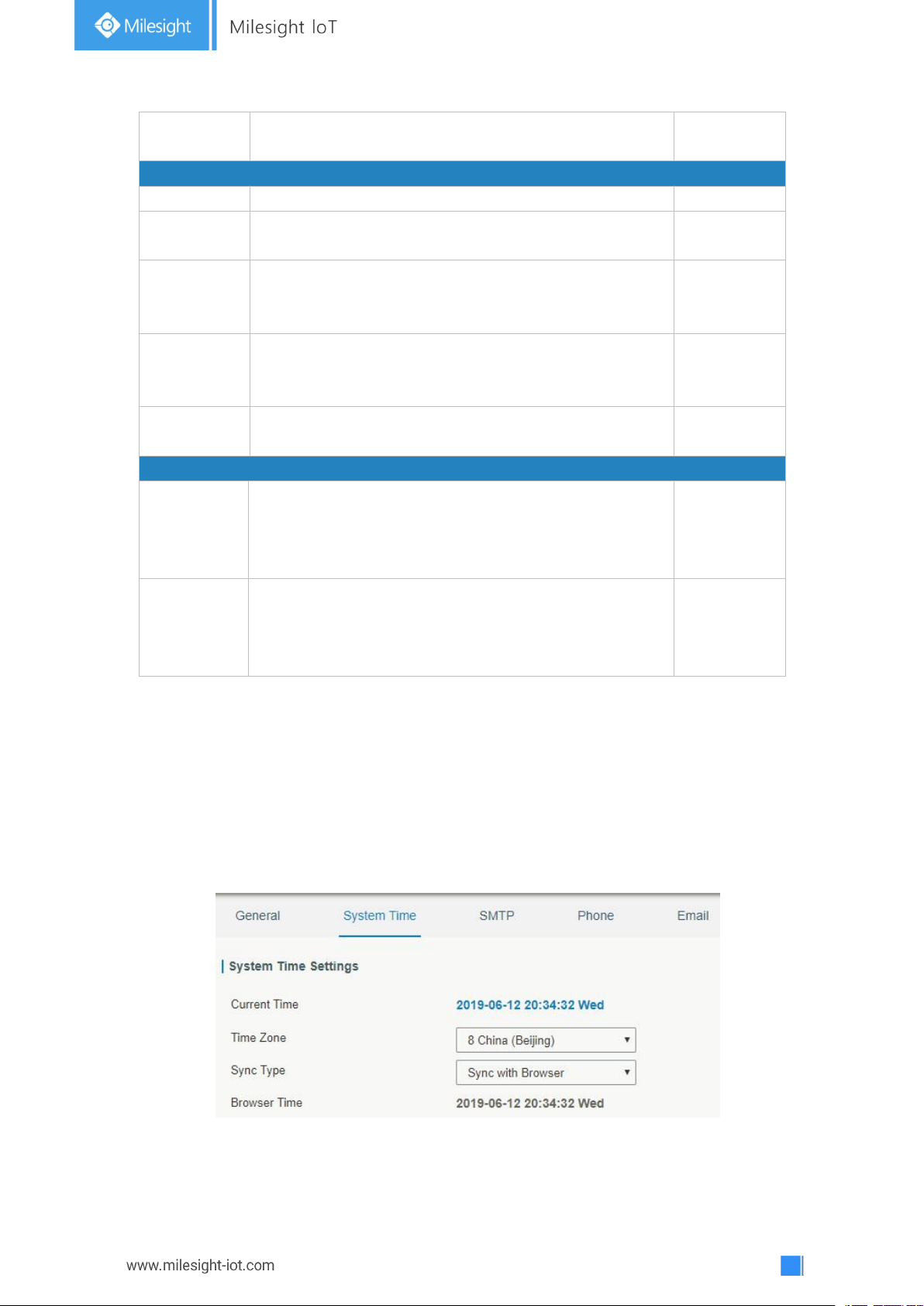
78
Web Login
Timeout (s)
You need to log in again if it times out. Range: 100-3600.
1800
Access Service
Port
Set port number of the services. Range: 1-65535.
--
HTTP
Users can log in the device locally via HTTP to access
and control it through Web after the option is checked.
80
HTTPS
Users can log in the device locally and remotely via
HTTPS to access and control it through Web after
option is checked.
443
TELNET
Users can log in the device locally and remotely via
TELNET to access and control it through Web after
option is checked.
23
SSH
Users can log in the device locally and remotely via SSH
after the option is checked.
22
HTTPS Certificates
Certificate
Click "Browse" button, choose certificate file on the PC,
and then click "Import" button to upload the file into
gateway. Click "Export" button will export the file to the
PC. Click "Delete" button will delete the file.
--
Key
Click "Browse" button, choose key file on the PC, and
then click "Import" button to upload the file into gateway.
Click "Export" button will export file to the PC.
Click "Delete" button will delete the file.
--
Table 3-4-1-1 General Setting Parameters
3.4.1.2 System Time
This section explains how to set the system time including time zone and time
synchronization type.
Note: to ensure that the gateway runs with the correct time, it’s recommended that you
set the system time when configuring the gateway.
Figure 3-4-1-2
Page 79
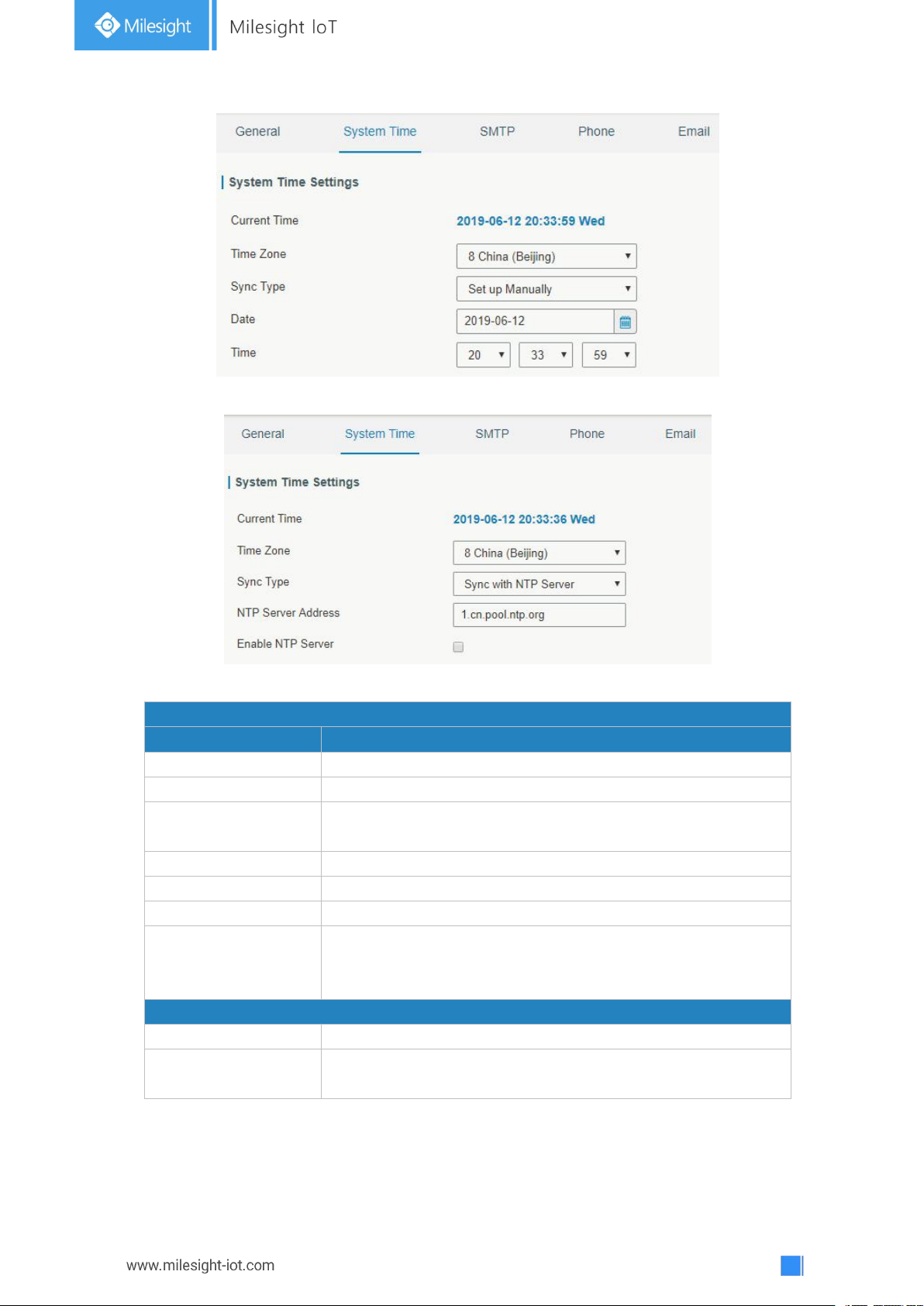
79
Figure 3-4-1-3
System Time
Item
Description
Current Time
Show the current system time.
Time Zone
Click the drop down list to select the time zone you are in.
Sync Type
Click the drop down list to select the time synchronization
type.
Sync with Browser
Synchronize time with browser.
Browser Time
Show the current time of browser.
Set up Manually
Manually configure the system time.
Sync with NTP Server
Synchronize time with NTP server so as to achieve time
synchronization of all devices equipped with a clock on
network.
Sync with NTP Server
NTP Server Address
Set NTP server address (domain name/IP).
Enable NTP Server
NTP client on the network can achieve time synchronization
with gateway after "Enable NTP Server" option is checked.
Figure 3-4-1-4
Table 3-4-1-2 System Time Parameters
Page 80
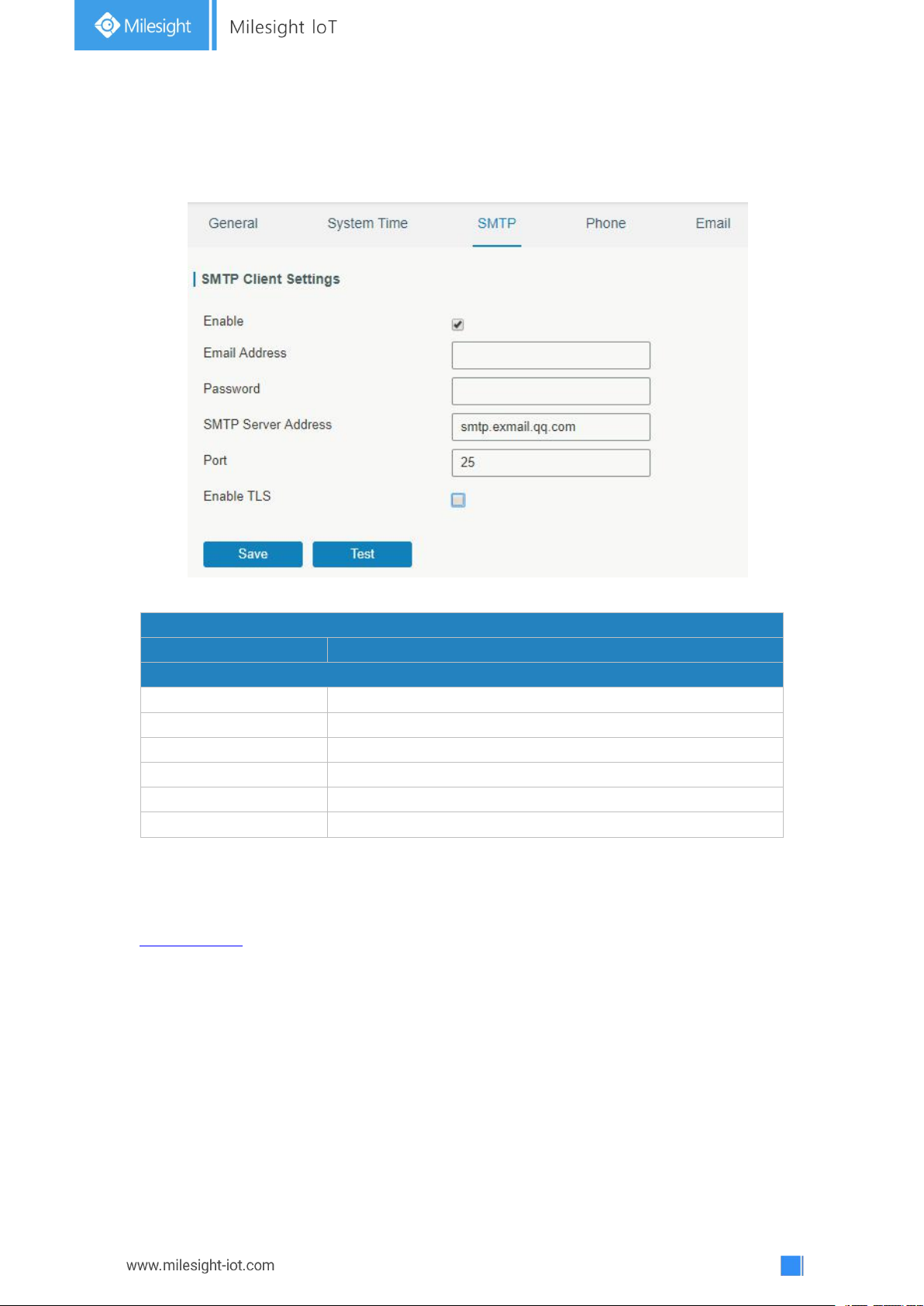
80
3.4.1.3 SMTP
SMTP
Item
Description
SMTP Client Settings
Enable
Enable or disable SMTP client function.
Email Address
Enter the sender's email account.
Password
Enter the sender's email password.
SMTP Server Address
Enter SMTP server's domain name.
Port
Enter SMTP server port. Range: 1-65535.
Enable TLS
Enable or disable TLS encryption.
SMTP, short for Simple Mail Transfer Protocol, is a TCP/IP protocol used in sending and
receiving e-mail. This section describes how to configure email settings.
Figure 3-4-1-5
Table 3-4-1-3 SMTP Setting
Related Topics
Events Setting
3.4.1.4 Phone
Phone settings involve in call/SMS trigger and SMS alarm for events.
1. Add phone list.
2. Select phone numbers and add them to the phone group.
3. Go to “Network > Interface > Cellular > Connection Mode > Connect on Demand >
Trigger by Call / Trigger by SMS” or go to “System > Events > Event Settings > SMS”
and then select the phone group ID.
Page 81
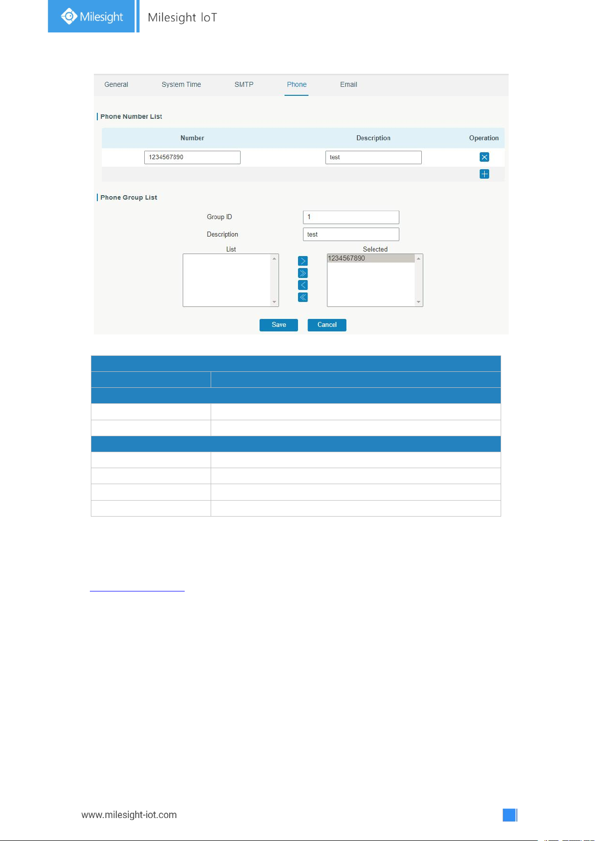
81
Phone
Item
Description
Phone Number List
Number
Enter the telephone number. Digits, "+" and "-" are allowed.
Description
The description of the telephone number.
Phone Group List
Group ID
Set number for phone group. Range: 1-100.
Description
The description of the phone group.
List
Show the phone list.
Selected
Show the selected phone number.
Related Topic
Connect on Demand
3.4.1.5 Email
Figure 3-4-1-6
Table 3-4-1-4 Phone Settings
Email settings involve email alarm for events.
1. Add email list.
2. Select email addresses and add them to the phone group.
3. Go to “System > Events > Event Settings > Email” and then select the email group ID.
Page 82
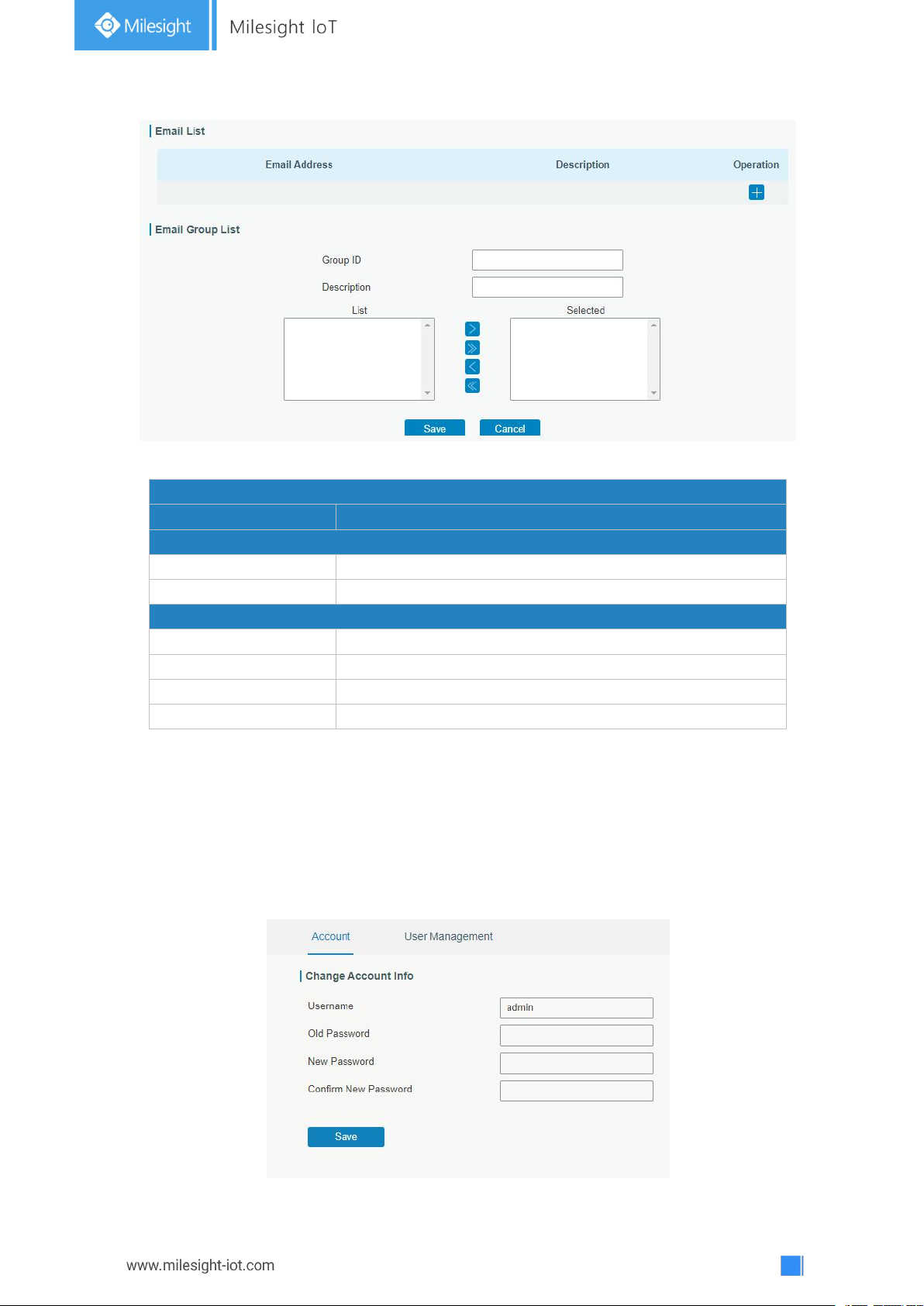
82
Figure 3-4-1-7
Email
Item
Description
Email List
Email Address
Enter the Email address.
Description
The description of the Email address.
Email Group List
Group ID
Set number for email group. Range: 1-100.
Description
The description of the Email group.
List
Show the Email address list.
Selected
Show the selected Email address.
Table 3-4-1-5 Email Settings
3.4.2 User Management
3.4.2.1 Account
Here you can change the login username and password of the administrator.
Note: it is strongly recommended that you modify them for the sake of security.
Page 83
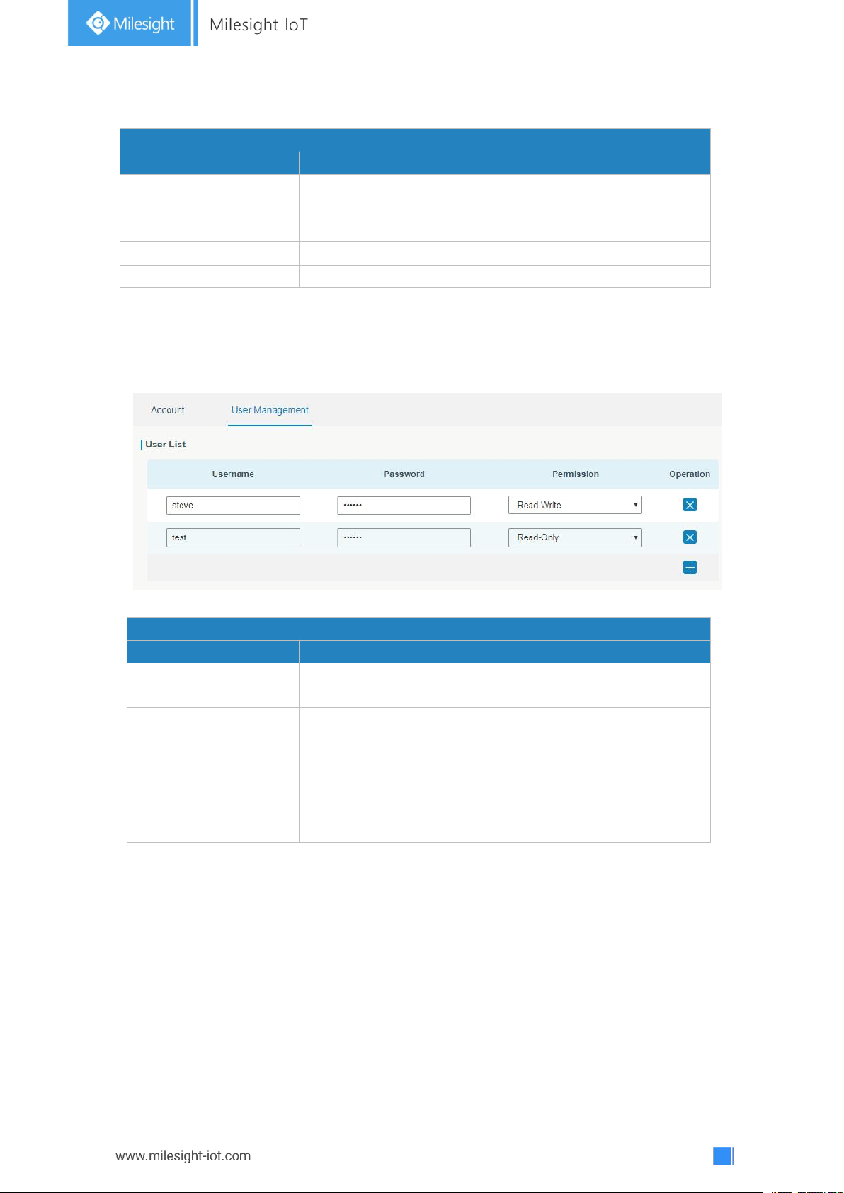
83
Figure 3-4-2-1
Account
Item
Description
Username
Enter a new username. You can use characters such as a-z,
0-9, "_", "-", "$". The first character can't be a digit.
Old Password
Enter the old password.
New Password
Enter a new password.
Confirm New Password
Enter the new password again.
User Management
Item
Description
Username
Enter a new username. You can use characters such as a-z,
0-9, "_", "-", "$". The first character can't be a digit.
Password
Set password.
Permission
Select user permission from “Read-Only” and “Read-Write”.
- Read-Only: users can only view the configuration of
gateway in this level.
- Read-Write: users can view and set the configuration of
gateway in this level.
Table 3-4-2-1 Account Information
3.4.2.2 User Management
This section describes how to create common user accounts.
The common user permission includes Read-Only and Read-Write.
Table 3-4-2-2 User Management
3.4.3 SNMP
SNMP is widely used in network management for network monitoring. SNMP exposes
management data with variables form in managed system. The system is organized in a
management information base (MIB) which describes the system status and configuration.
These variables can be remotely queried by managing applications.
Configuring SNMP in networking, NMS, and a management program of SNMP should be
set up at the Manager.
Configuration steps are listed as below for achieving query from NMS:
Figure 3-4-2-2
Page 84
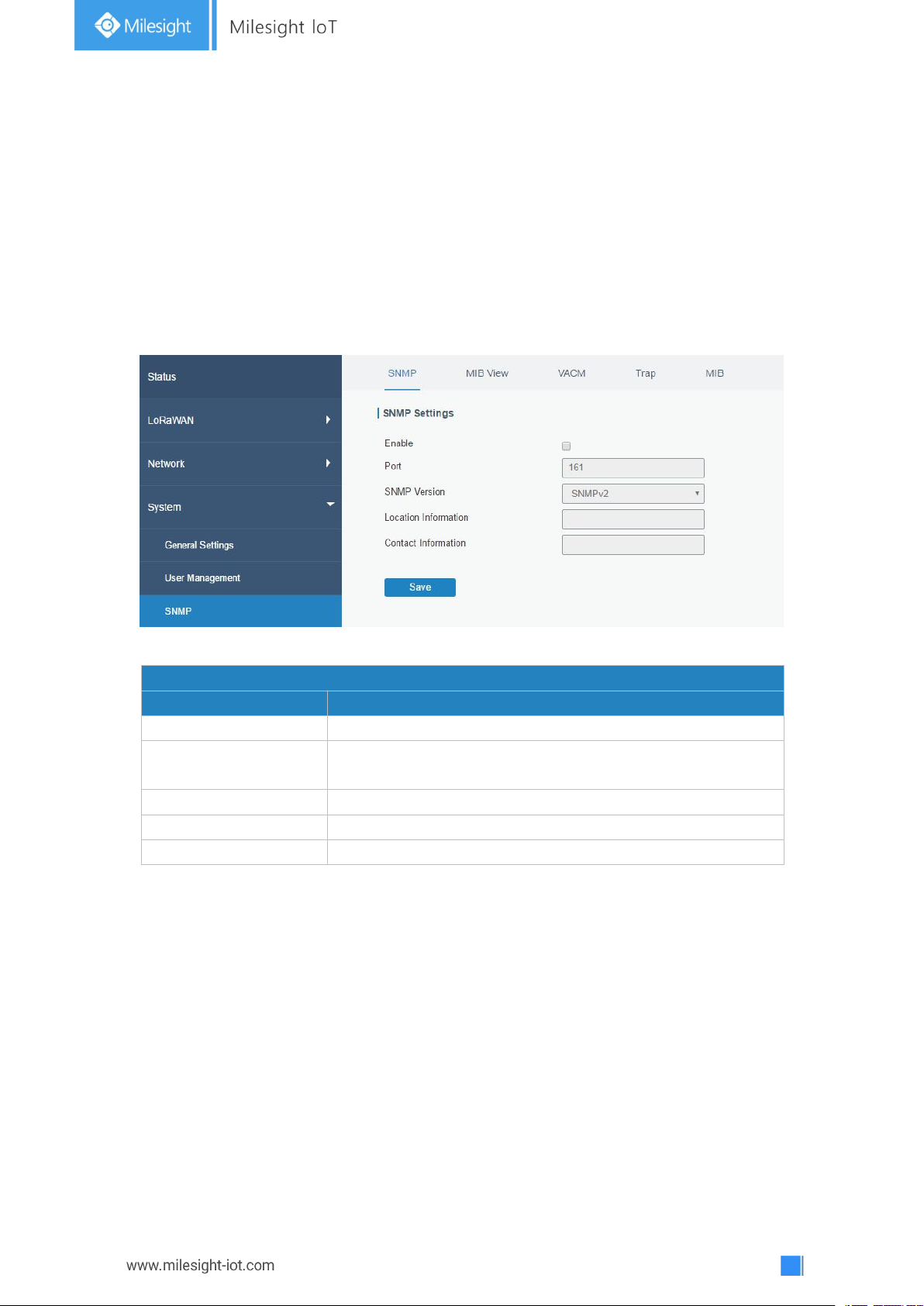
84
1. Enable SNMP setting.
SNMP Settings
Item
Description
Enable
Enable or disable SNMP function.
Port
Set SNMP listened port. Range: 1-65535.
The default port is 161.
SNMP Version
Select SNMP version; support SNMP v1/v2c/v3.
Location Information
Fill in the location information.
Contact Information
Fill in the contact information.
2. Download MIB file and load it into NMS.
3. Configure MIB View.
4. Configure VCAM.
3.4.3.1 SNMP
UG67 supports SNMPv1, SNMPv2c and SNMPv3 version. SNMPv1 and SNMPv2c employ
community name authentication. SNMPv3 employs authentication encryption by username
and password.
Figure 3-4-3-1
Table 3-4-3-1 SNMP Parameters
3.4.3.2 MIB View
This section explains how to configure MIB view for the objects.
Page 85
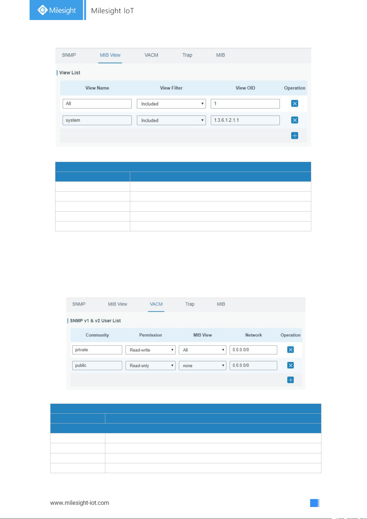
85
Figure 3-4-3-2
MIB View
Item
Description
View Name
Set MIB view's name.
View Filter
Select from "Included" and "Excluded".
View OID
Enter the OID number.
Included
You can query all nodes within the specified MIB node.
Excluded
You can query all nodes except for the specified MIB node.
VACM
Item
Description
SNMP v1 & v2 User List
Community
Set the community name.
Permission
Select from "Read-Only" and "Read-Write".
MIB View
Select an MIB view to set permissions from the MIB view list.
Network
The IP address and bits of the external network accessing the MIB view.
Table 3-4-3-2 MIB View Parameters
3.4.3.3 VACM
This section describes how to configure VCAM parameters.
Figure 3-4-3-3
Page 86
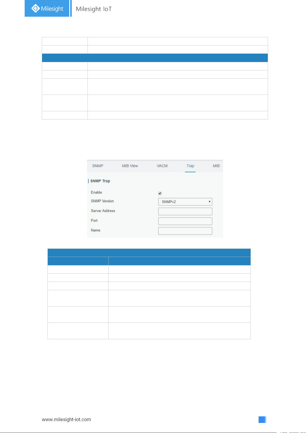
86
Read-Write
The permission of the specified MIB node is read and write.
Read-Only
The permission of the specified MIB node is read only.
SNMP v3 User List
Group Name
Set the name of SNMPv3 group.
Security Level
Select from "NoAuth/NoPriv", "Auth/NoPriv", and " Auth/Priv".
Read-Only View
Select an MIB view to set permission as "Read-only" from the MIB view
list.
Read-Write View
Select an MIB view to set permission as "Read-write" from the MIB view
list.
Inform View
Select an MIB view to set permission as "Inform" from the MIB view list.
Table 3-4-3-3 VACM Parameters
SNMP Trap
Item
Description
Enable
Enable or disable SNMP Trap function.
SNMP Version
Select SNMP version; support SNMP v1/v2c/v3.
Server Address
Fill in NMS's IP address or domain name.
Port
Fill in UDP port. Port range is 1-65535. The default port is
162.
Name
Fill in the group name when using SNMP v1/v2c; fill in
the username when using SNMP v3.
Auth/Priv Mode
Select from "NoAuth & No Priv", "Auth & NoPriv", and
"Auth & Priv".
3.4.3.4 Trap
This section explains how to enable network monitoring by SNMP trap.
Figure 3-4-3-4
Table 3-4-3-4 Trap Parameters
3.4.3.5 MIB
This section describes how to download MIB files.
Page 87
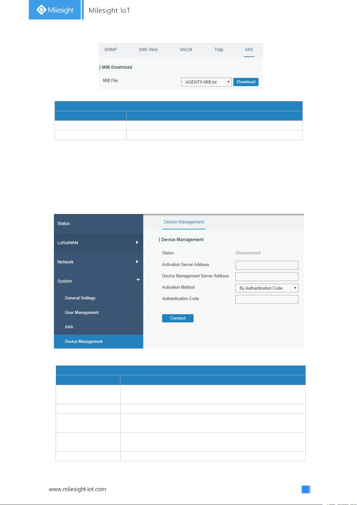
87
Figure 3-4-3-5
MIB
Item
Description
MIB File
Select the MIB file you need.
Download
Click "Download" button to download the MIB file to PC.
DeviceHub
Item
Description
Status
Show the connection status between the gateway and the
DeviceHub.
Disconnected
Click this button to disconnect the gateway from the DeviceHub.
Activation Server
Address
IP address or domain of the DeviceHub.
DeviceHub Server
Address
The URL address for the device to connect to the DeviceHub,
e.g. http://220.82.63.79:8080/acs.
Activation Method
Select activation method to connect the gateway to the
Table 3-4-3-5 MIB Download
3.4.5 Device Management
You can connect the device to the DeviceHub on this page so as to manage the gateway
centrally and remotely.
Figure 3-4-5-1
Page 88
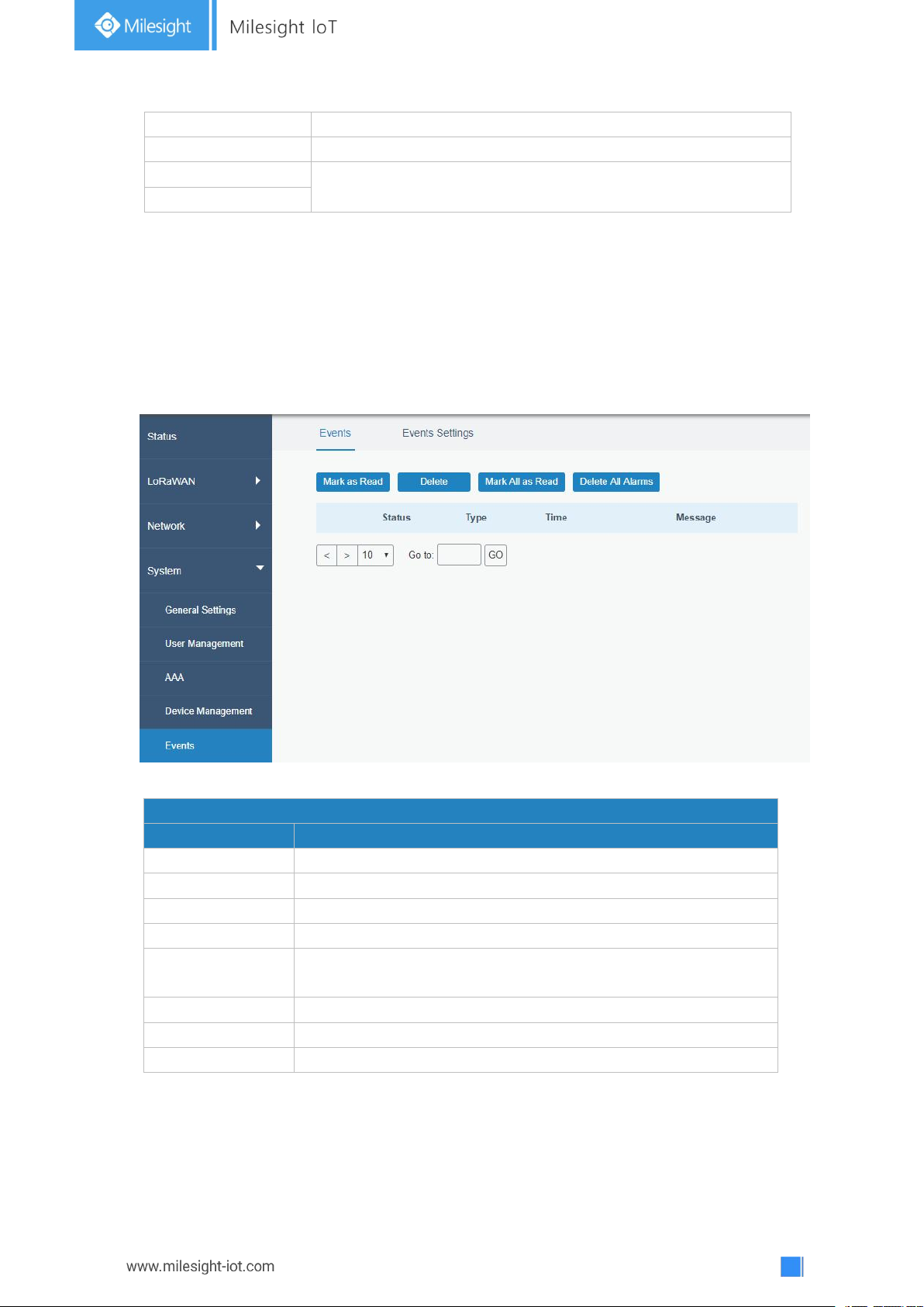
88
DeviceHub server, options are "By Authentication ID" and "By ID".
Authentication Code
Fill in the authentication code generated from the DeviceHub.
ID
Fill in the registered DeviceHub account (email) and password.
Password
Table 3-4-5-1
Events
Item
Description
Mark as Read
Mark the selected event alarm as read.
Delete
Delete the selected event alarm.
Mark All as Read
Mark all event alarms as read.
Delete All Alarms
Delete all event alarms.
Status
Show the reading status of the event alarms, such as “Read” and
“Unread”.
Type
Show the event type that should be alarmed.
Time
Show the alarm time.
Message
Show the alarm content.
3.4.6 Events
Event feature is capable of sending alerts by Email when certain system events occur.
3.4.6.1 Events
You can view alarm messages on this page.
Figure 3-4-6-1
Table 3-4-6-1 Events Parameters
Page 89
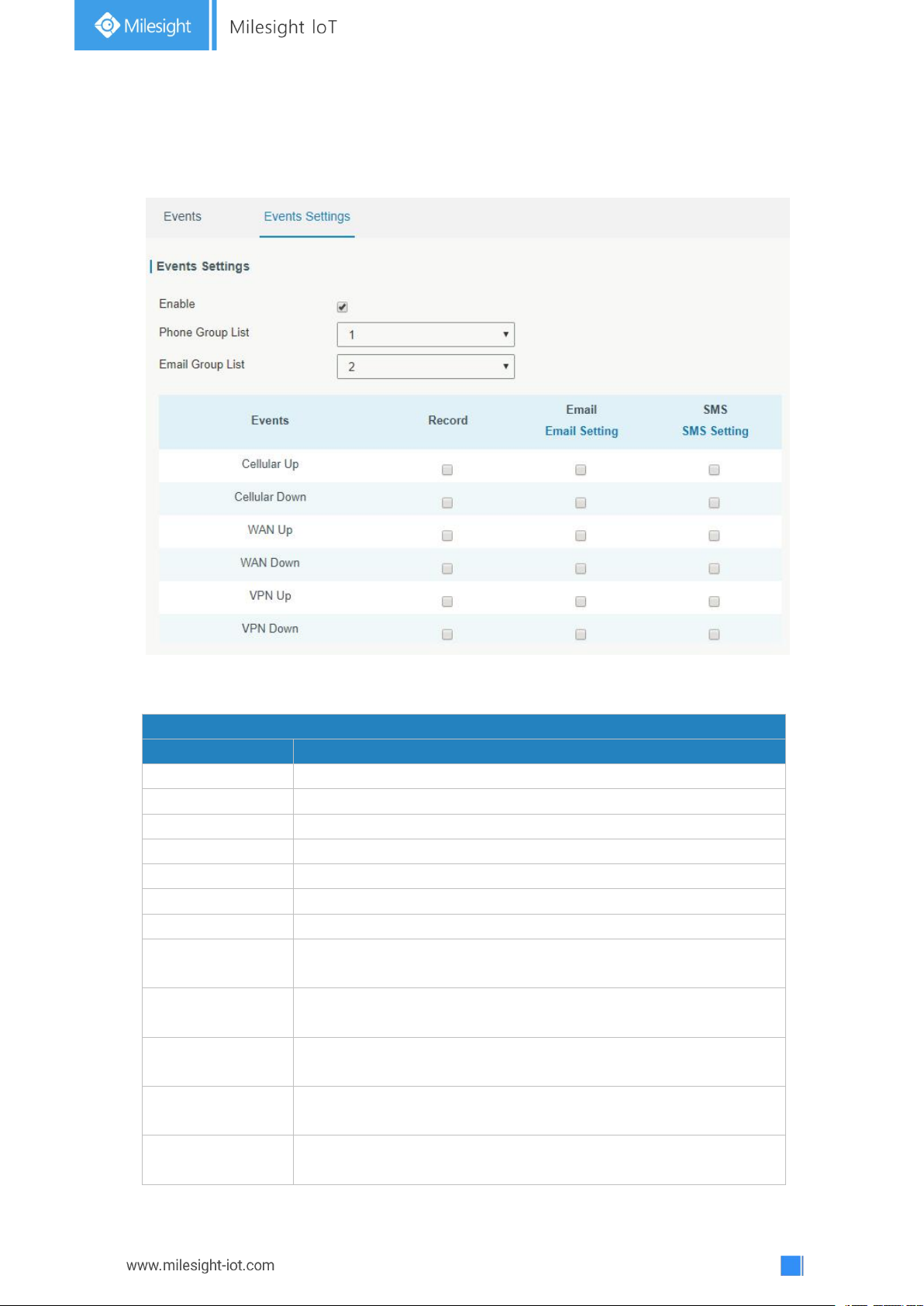
89
3.4.6.2 Events Settings
Event Settings
Item
Description
Enable
Check to enable "Events Settings".
Cellular Up
Cellular network is connected.
Cellular Down
Cellular network is disconnected.
WAN Up
Ethernet cable is connected to WAN port.
WAN Down
Ethernet cable is disconnected to WAN port.
VPN Up
VPN is connected.
VPN Down
VPN is disconnected.
Record
The relevant content of event alarm will be recorded on "Event"
page if this option is checked.
Email
The relevant content of event alarm will be sent out via email if
this option is checked.
Email Setting
Click and you will be redirected to the page "Email" to configure
the Email group.
SMS
The relevant content of event alarm will be sent out via SMS if
this option is checked.
SMS Setting
Click and you will be redirected to the page of "Phone" to
configure phone group list.
In this section, you can decide what events to record and whether you want to receive
email and SMS notifications when any change occurs.
Figure 3-4-6-2
Page 90
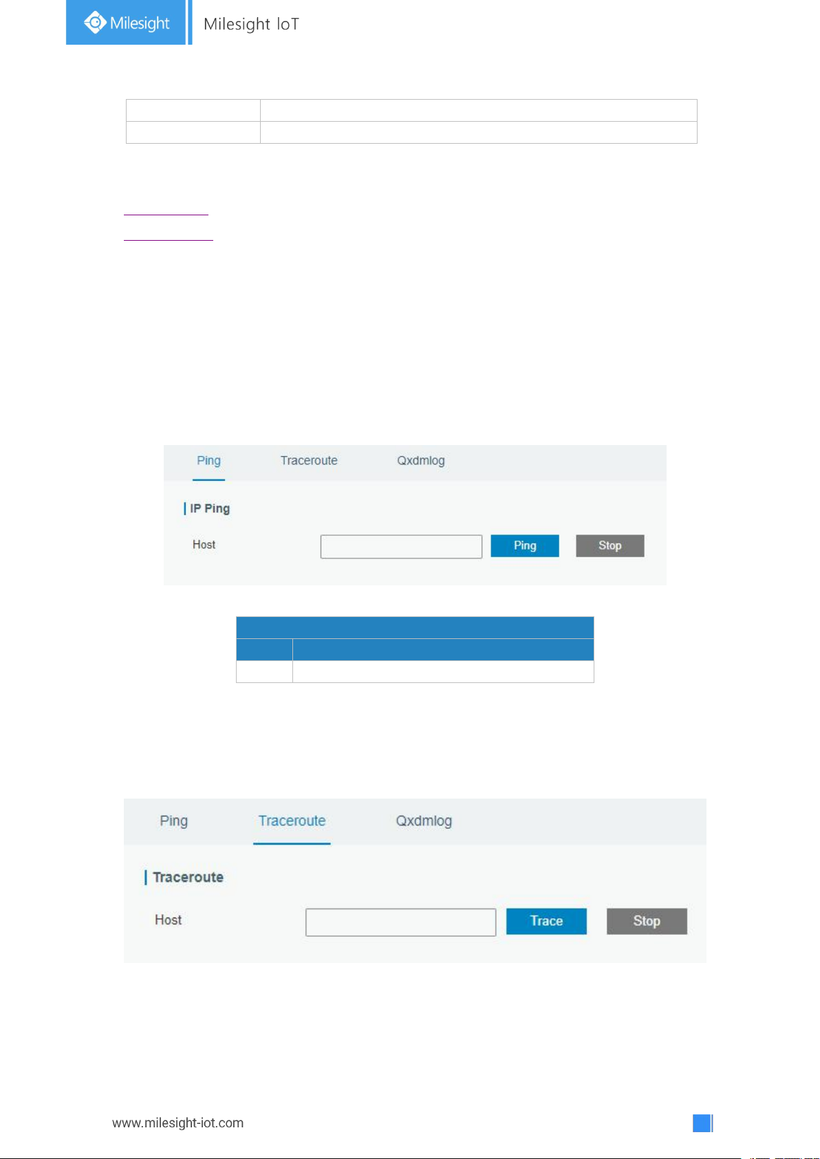
90
Phone Group List
Select phone group to receive SMS alarm.
Email Group List
Select Email group to receive Email alarm.
Table 3-4-6-2 Events Parameters
PING
Item
Description
Host
Ping outer network from the gateway.
Related Topics
Email Setting
Phone Setting
3.5 Maintenance
This section describes system maintenance tools and management.
3.5.1 Tools
Troubleshooting tools includes ping and traceroute.
3.5.1.1 Ping
Ping tool is engineered to ping outer network.
Figure 3-5-1-1
Table 3-5-1-1 IP Ping Parameters
3.5.1.2 Traceroute
Traceroute tool is used for troubleshooting network routing failures.
Figure 3-5-1-2
Page 91
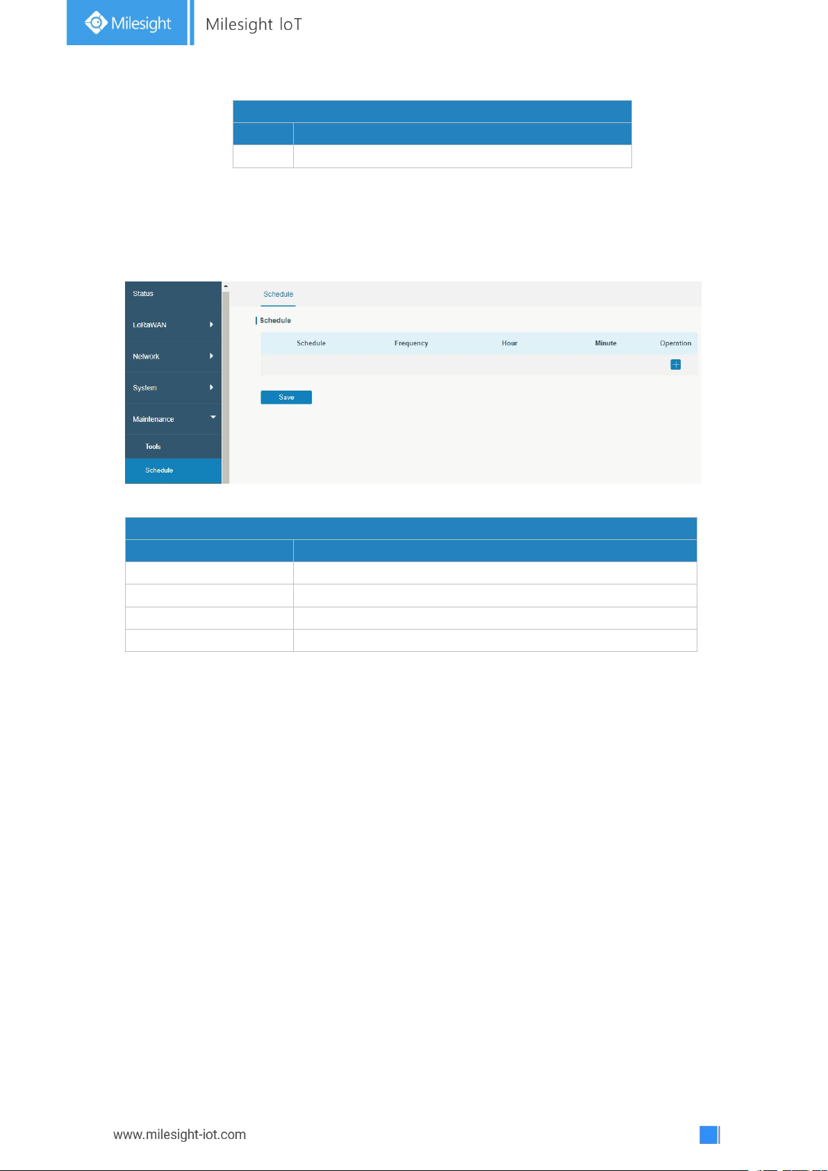
91
Traceroute
Item
Description
Host
Address of the destination host to be detected.
Table 3-5-1-2 Traceroute Parameters
Schedule
Item
Description
Schedule
Select schedule type.
Reboot
Reboot the gateway regularly.
Frequency
Select the frequency to execute the schedule.
Hour & Minute
Select the time to execute the schedule.
3.5.2 Schedule
This section explains how to configure scheduled reboot on the gateway.
Figure 3-5-2-1
Table 3-5-2-1 Schedule Parameters
3.5.3 Log
The system log contains a record of informational, error and warning events that indicates
how the system processes. By reviewing the data contained in the log, an administrator or
user troubleshooting the system can identify the cause of a problem or whether the system
processes are loading successfully. Remote log server is feasible, and gateway will upload
all system logs to remote log server such as Syslog Watcher.
3.5.3.1 System Log
This section describes how to download log file and view the recent log on web.
Page 92
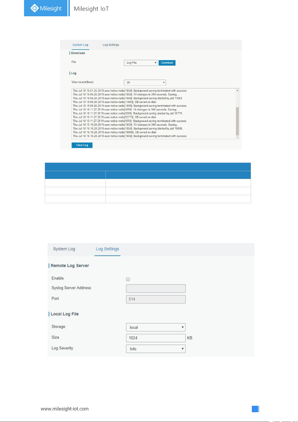
92
Figure 3-5-3-1
System Log
Item
Description
Download
Download log file.
View recent (lines)
View the specified lines of system log.
Clear Log
Clear the current system log.
Table 3-5-3-1 System Log Parameters
3.5.3.2 Log Settings
This section explains how to enable remote log server and local log setting.
Figure 3-5-3-2
Page 93
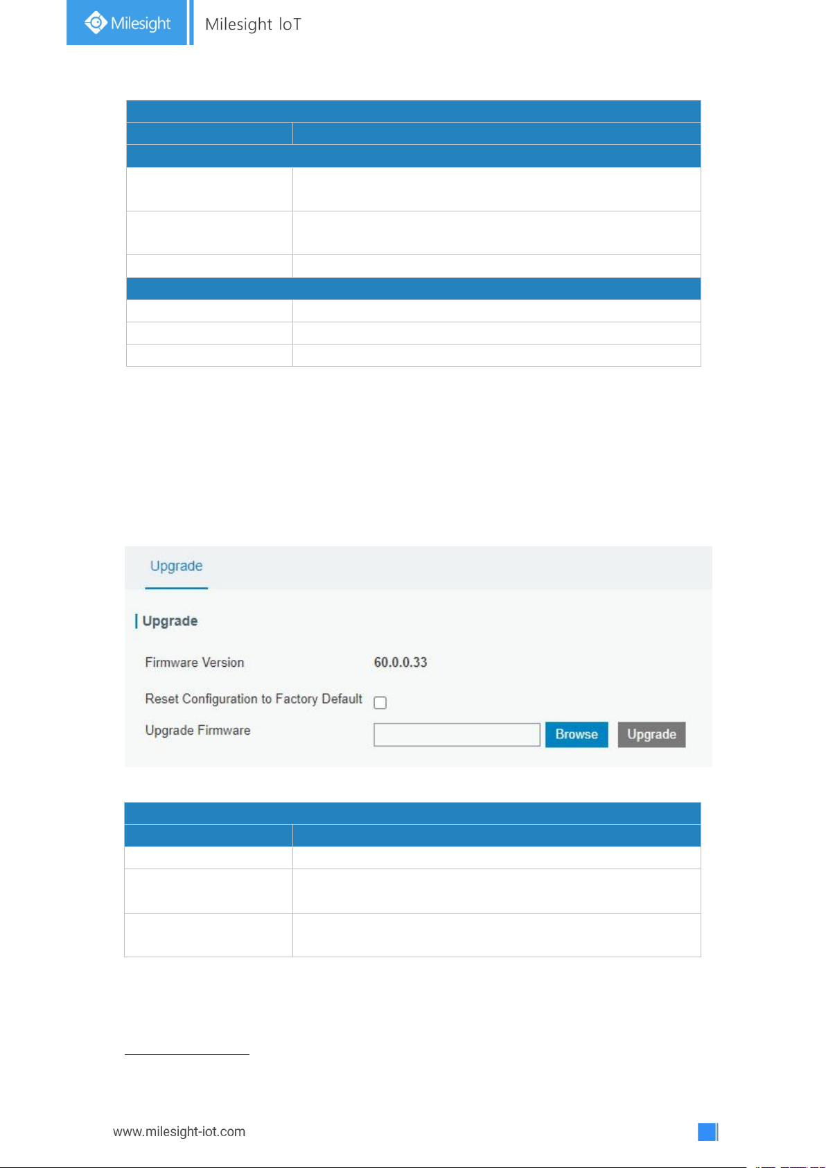
93
Log Settings
Item
Description
Remote Log Server
Enable
With “Remote Log Server” enabled, gateway will send all
system logs to the remote server.
Syslog Server Address
Fill in the remote system log server address (IP/domain
name).
Port
Fill in the remote system log server port.
Local Log File
Storage
User can store the log file in memory or TF card.
Size
Set the size of the log file to be stored.
Log Severity
The list of severities follows the syslog protocol.
Table 3-5-3-2 System Log Parameters
Upgrade
Item
Description
Firmware Version
Show the current firmware version.
Reset Configuration to
Factory Default
When this option is checked, the gateway will be reset to
factory defaults after upgrade.
Upgrade Firmware
Click "Browse" button to select the new firmware file, and
click "Upgrade" to upgrade firmware.
3.5.4 Upgrade
This section describes how to upgrade the gateway firmware via web. Generally you don’t
need to do the firmware upgrade.
Note: any operation on web page is not allowed during firmware upgrade, otherwise the
upgrade will be interrupted, or even the device will break down.
Table 3-5-4-1 Upgrade Parameters
Related Configuration Example
Firmware Upgrade
Figure 3-5-4-1
Page 94
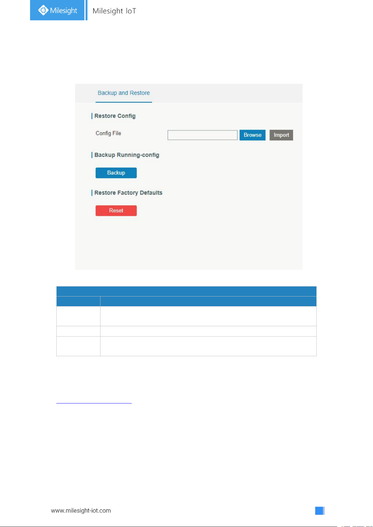
94
3.5.5 Backup and Restore
Backup and Restore
Item
Description
Config File
Click "Browse" button to select configuration file, and then click "Import"
button to upload the configuration file to the gateway.
Backup
Click "Backup" to export the current configuration file to the PC.
Reset
Click "Reset" button to reset factory default settings. gateway will
restart after reset process is done.
This section explains how to create a complete backup of the system configurations to a
file, restore the config file to the gateway and reset to factory defaults.
Figure 3-5-5-1
Table 3-5-5-1 Backup and Restore Parameters
Related Configuration Example
Restore Factory Defaults
3.5.6 Reboot
On this page you can reboot the gateway and return to the login page. We strongly
recommend clicking “Save” button before rebooting the gateway so as to avoid losing the
new configuration.
Page 95
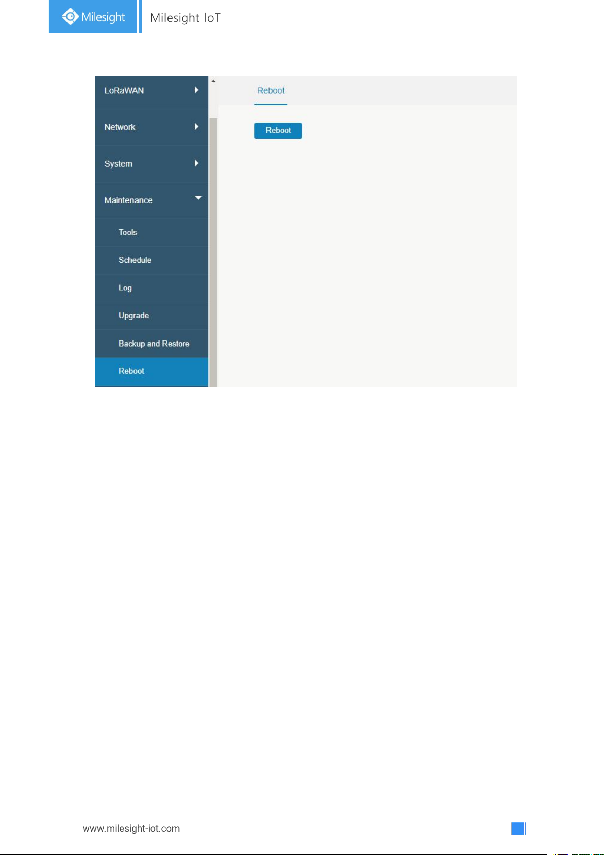
95
Figure 3-5-6-1
3.6 APP
3.6.1 Python
Python is an object-oriented programming language that has gained popularity because of
its clear syntax and readability.
As an interpreted language, Python has a design philosophy that emphasizes code
readability, notably using whitespace indentation to delimit code blocks rather than curly
brackets or keywords, and a syntax that allows programmers to express concepts in fewer
lines of code than it’s used in other languages such as C++ or Java. The language provides
constructs and intends to enable writing clear programs on both small and large scale.
Users can use Python to quickly generate the prototype of the program, which can be the
final interface of the program, rewrite it with a more appropriate language, and then
encapsulate the extended class library that Python can call.
This section describes how to view the relevant running status such as App-manager, SDK
version, extended storage, etc. Also you can change the App-manager configuration, and
import the Python App package from here.
Page 96
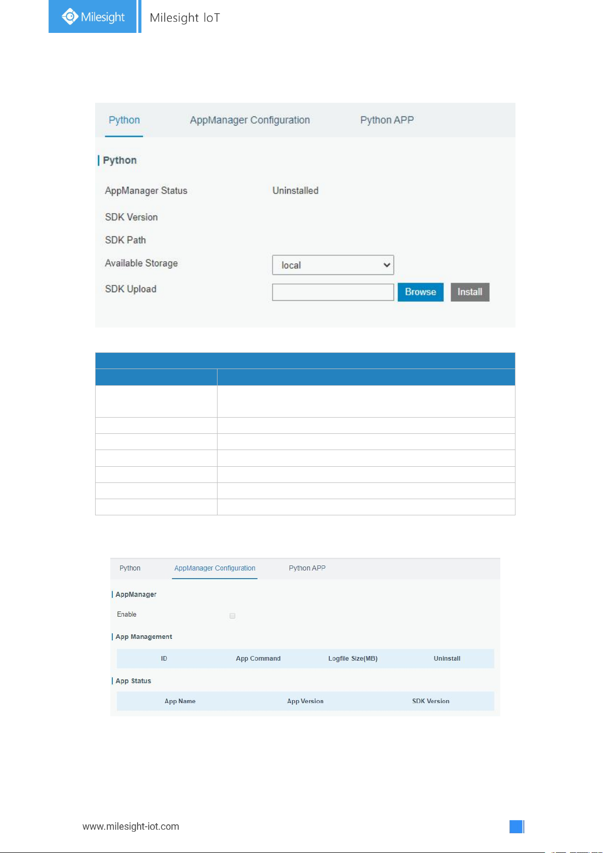
96
3.6.1.1 Python
Python
Item
Description
AppManager Status
Show AppManager's running status, like "Uninstalled",
"Running" or "Stopped".
SDK Version
Show the version of the installed SDK.
SDK Path
Show the SDK installation path.
Available Storage
Select available storage to install SDK.
SDK Upload
Upload and install SDK for Python.
Uninstall
Uninstall SDK.
View
View application status managed by AppManager.
Figure 3-6-1-1
Table 3-6-1-1 Python Parameters
3.6.1.2 App Manager Configuration
Figure 3-6-1-2
Page 97
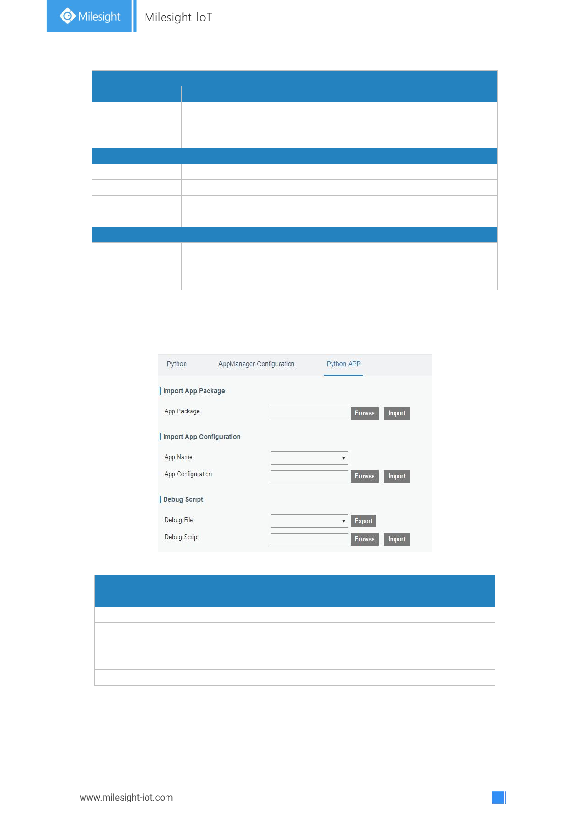
97
AppManager Configuration
Item
Description
Enable
After enabling Python AppManager, user can click "View" button on
the "Python" webpage to view the application status managed by
AppManager.
App Management
ID
Show the ID of the imported App.
App Command
Show the name of the imported App.
Logfile Size(MB)
User-defined Logfile size. Range: 1-50.
Uninstall
Uninstall APP.
App Status
App Name
Show the name of the imported App.
App Version
Show the version of the imported App.
SDK Version
Show the SDK version which the imported App is based on.
3.6.1.3 Python App
Python APP
Item
Description
App Package
Select App package and import.
App Name
Select App to import configuration.
App Configuration
Select configuration file and import.
Debug File
Export script file.
Debug Script
Select Python script to be debugged and import.
Table 3-6-1-2 APP Manager Parameters
Figure 3-6-1-3
Table 3-6-1-3 APP Parameters
Page 98
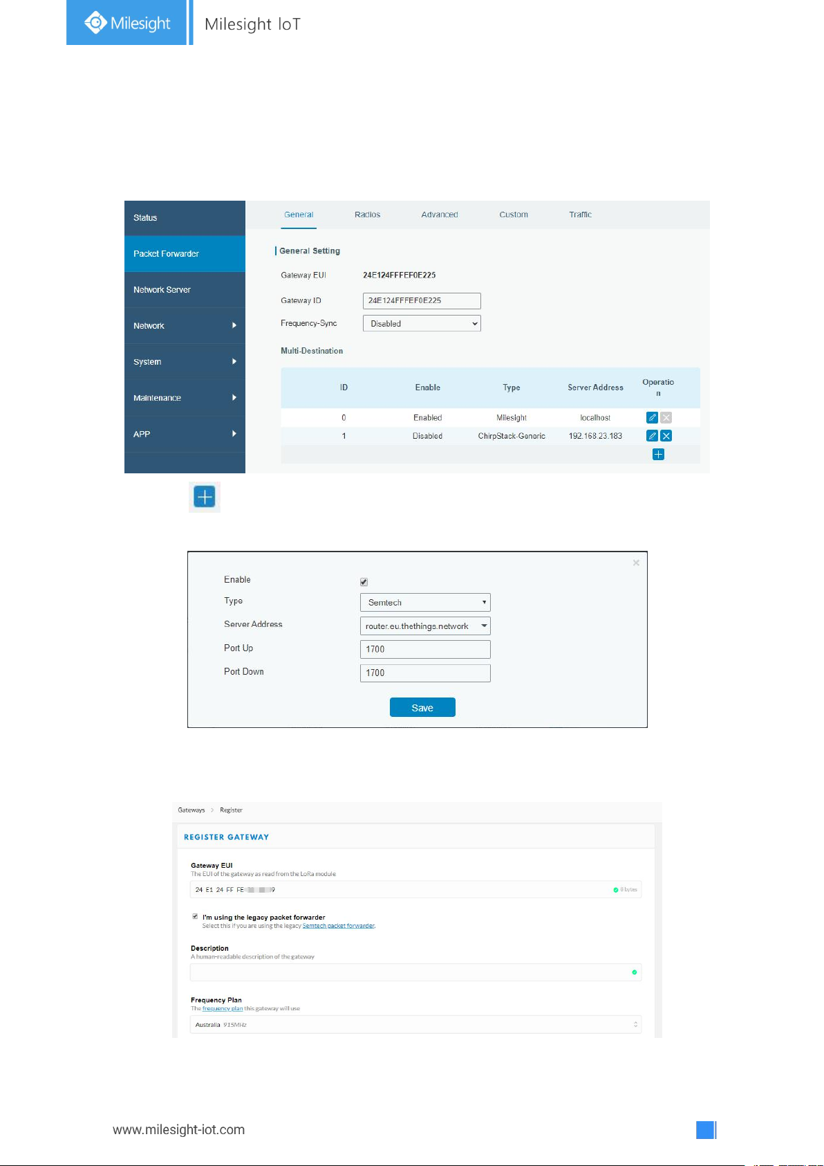
98
Chapter 4 Application Examples
4.1 Packet Forwarder Configuration
1. Go to “Packet Forwarder” > “General”.
2. Click to add a new network server. “Milesight” type indicates the gateway
network server.
3. Add the gateway on network server page. Take TTN for example, type and save the
gateway EUI and other information when you connect it via Semtech packet forwarder.
After you add the gateway, TTN will show connection status.
Page 99

99
4. Go to “Traffic” page to view the data communication of UG67.
4.2 Application Configuration
You can create a new application on this page, which is mainly used to define the method
of decoding the data sent from end-device and choosing the data transport protocol to
send data to another server address. The data will be sent to your custom server address
using MQTT, HTTP or HTTPS protocol.
1. Go to “Network Server” > “Application”.
2. Click to enter the configuration page, displayed as the following picture:
3. Click to add a data transmission type of HTTP or HTTPS:
Step 1: select HTTP or HTTPS as transmission protocol.
Step 2: Enter the header name and header value as needed.
Page 100
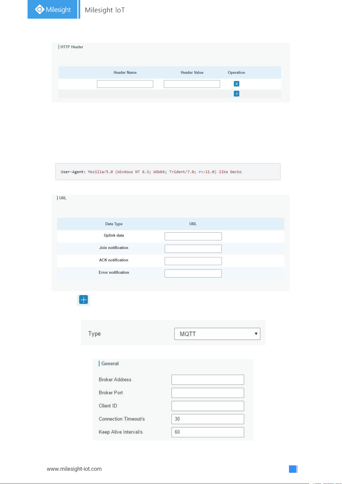
100
Headers are name/value pairs that appear in both request and response messages. The
name of the header is separated from the value by a single colon.
For example, this request message provides a header called User-Agent whose value is
Mozilla/5.0 (Windows NT 6.3; WOW64; Trident/7.0; rv:11.0) like Gecko. The purpose of this
particular header is to supply the web server with information about the type of browser
making the request.
Step 3: Enter the destination URL. Different types of data can be sent to different URLs.
4. Click to add a data transmission type of MQTT:
Step 1: select the transmission protocol as MQTT.
Step 2: Fill in general settings.
 Loading...