

Page 1

Milesight IoT
UC51x Series
User Guide
Page 2
2
Safety Precautions
Date
Doc Version
Description
Feb. 20, 2021
V 1.0
Initial version
Milesight will not shoulder responsibility for any loss or damage resulting from not following the
instructions of this operating guide.
The device must not be remodeled in any way.
Do not place the device close to objects with naked flames.
Do not place the device where the temperature is below/above the operating range.
Make sure electronic components do not drop out of the enclosure while opening.
When installing the battery, please install it accurately, and do not install the reverse or
wrong model.
The device must never be subjected to shocks or impacts.
Declaration of Conformity
UC51x series is in conformity with the essential requirements and other relevant provisions of
the CE, FCC, and RoHS.
Copyright©2011-2021 Milesight. All rights reserved.
All information in this guide is protected by copyright law. Whereby, no organization or individual
shall copy or reproduce the whole or part of this user guide by any means without written
authorization from Xiamen Milesight IoT Co., Ltd.
For assistance, please contact
Milesight technical support:
Email: [email protected]
Tel: 86-592-5085280
Fax: 86-592-5023065
Address: 4/F, No.63-2 Wanghai Road,
2ndSoftware Park, Xiamen, China
Revision History
Page 3
3
Contents
1. Product Introduction
1.1 Overview
1.2 Features
2. Hardware Introduction
2.1 Packing List
2.2 Hardware Overview
2.3 Power Button
2.4 Dimensions(mm)
3. Installation
4. Operation Guide
4.1 Log in the ToolBox
4.2 Solenoid Valve Control
4.3 LoRaWAN Settings
4.4 Solenoid Settings
4.5 Maintenance
5. Milesight IoT Cloud Management
5.1 Add a Milesight Gateway
5.2 Add UC51x to Milesight IoT Cloud
5.3 Solenoid Valve Control
6. Device Payload
..................................................................................................................................................
4.1.1 NFC Configuration
4.1.2 USB Configuration
4.5.1 Upgrade
4.5.2 Backup
4.5.3 Reset to Factory Default
.................................................................................................................................
...........................................................................................................................................
............................................................................................................................................
..............................................................................................................................
......................................................................................................................................
.........................................................................................................................
...................................................................................................................................
............................................................................................................................
.........................................................................................................................................
..........................................................................................................................
...............................................................................................................
...............................................................................................................
.................................................................................................................
.......................................................................................................................
..........................................................................................................................
..................................................................................................................................
...............................................................................................................................
.................................................................................................................................
.............................................................................................................
.................................................................................................................
........................................................................................................................................
...................................................................................................
........................................................................................................
.............................................................................................
4
4
4
4
4
5
5
6
6
8
8
8
9
10
11
14
15
15
16
17
18
18
19
21
22
Page 4
4
1. Product Introduction
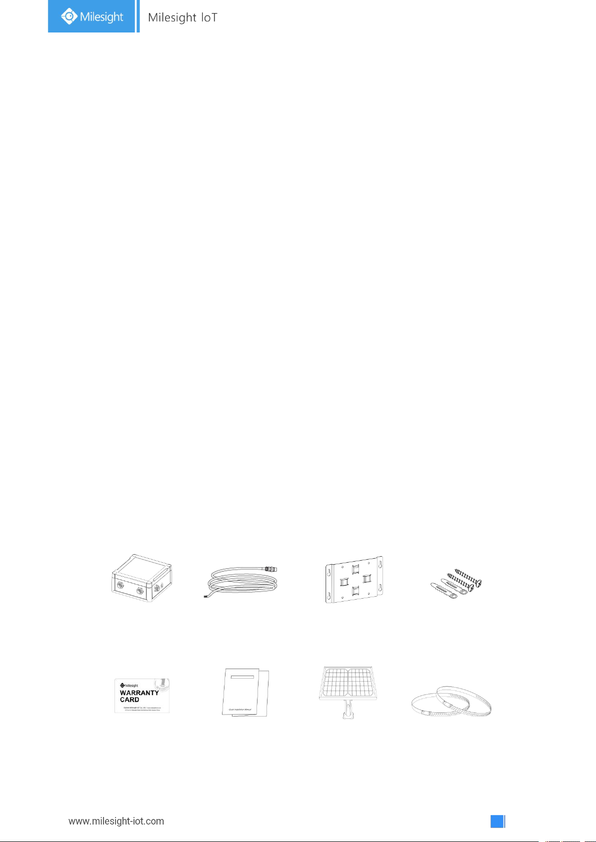
1 × Warranty Card
1 × Quick Guide
1 × Solar Panel Kit
(UC511 Optional)
2 × Hose Clamps
(Optional)
1 × U51x Device
3 × Data Cables
(1.5m)
1 × Mounting
Bracket
Wall Mounting Kits
1.1 Overview
UC51x series LoRaWAN®wireless solenoid valve controller is a device used to remotely control
DC latching solenoids of the valve. It contains 2 solenoid interfaces and 1 pulse interface, which
can be easily controlled locally or remotely.
Besides ultra-low-power LoRaWAN®technology, UC51x series also provides both solar and
built-in battery power supply for uninterrupted operation. For outdoor applications, it equips with
IP67-rated enclosure and M12 connectors to protect from water and dust under harsh
environments.
1.2 Features
Compatible with standard DC latching solenoids
OPEN/CLOSE control by mobile APP locally or commands remotely
One pulse water meter interface for flow monitoring
Transmission distance up to 11km with line of sight
Waterproof design including IP67 case and M12 connectors
Solar powered and built-in chargeable battery
Quick wireless configuration via NFC
Time and flow control via Milesight IoT Cloud
2. Hardware Introduction
2.1 Packing List
Page 5
5
If any of the above items is missing or damaged, please contact your sales Representative.
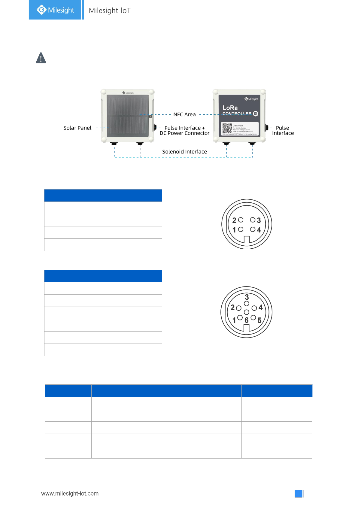
Pin
Description
1
GND
2
GPIO(for wiring switch)
3
CLOSE(Black)
4
OPEN(Red)
Pin
Description
1
GPIO2
2
VCC(5-24V)
3
GND
4
GPIO1
5
GND
6
GND
Function
Action
LED Indication
Turn On
Press and hold the button for more than 3s.
Off → On
Turn Off
Press and hold the button for more than 3s.
On -> Off
Reset
Press and hold the button for more than 10s.
Blinks.
Check
On/Off Status
Quickly press the power button.
Light On: Device is on.
Light Off: Device is off.
2.2 Hardware Overview
UC511 UC512
Solenoid Interfaces:
Pulse Interface/DC:
2.3 Power Button
Page 6
6
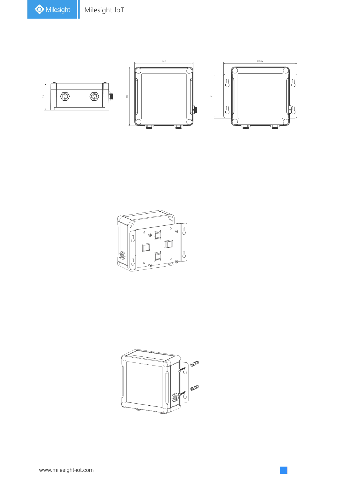
2.4 Dimensions(mm)
3. Installation
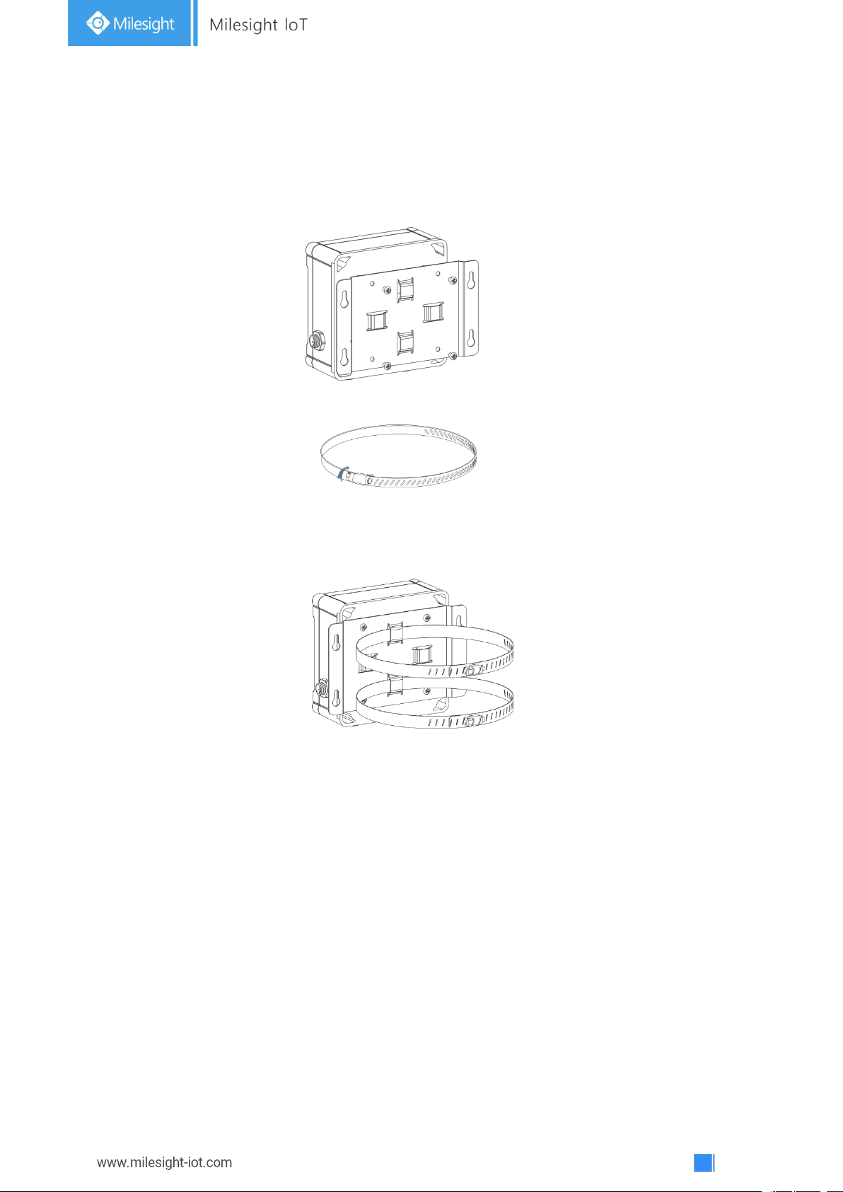
Wall Mounting
Make sure you have wall mounting bracket, bracket mounting screws, wall plugs, wall mounting
screws and other required tools.
Steps:
1. Mount the enclosure to the mounting bracket with the bracket mounting screws.
2. Align the mounting bracket horizontally to the desired position on the wall, use a marker pen
to mark four mounting holes on the wall, and then remove the mounting bracket from the wall.
Note: The connecting lines of adjacent points are at right angles.
3. Drill the four holes by using your drill with a 6 mm drill bit on the positions you marked
previously on the wall.
4. Insert four wall plugs into the holes respectively.
5. Mount the mounting bracket horizontally to the wall by fixing the wall mounting screws into
the wall plugs.
Page 7
7
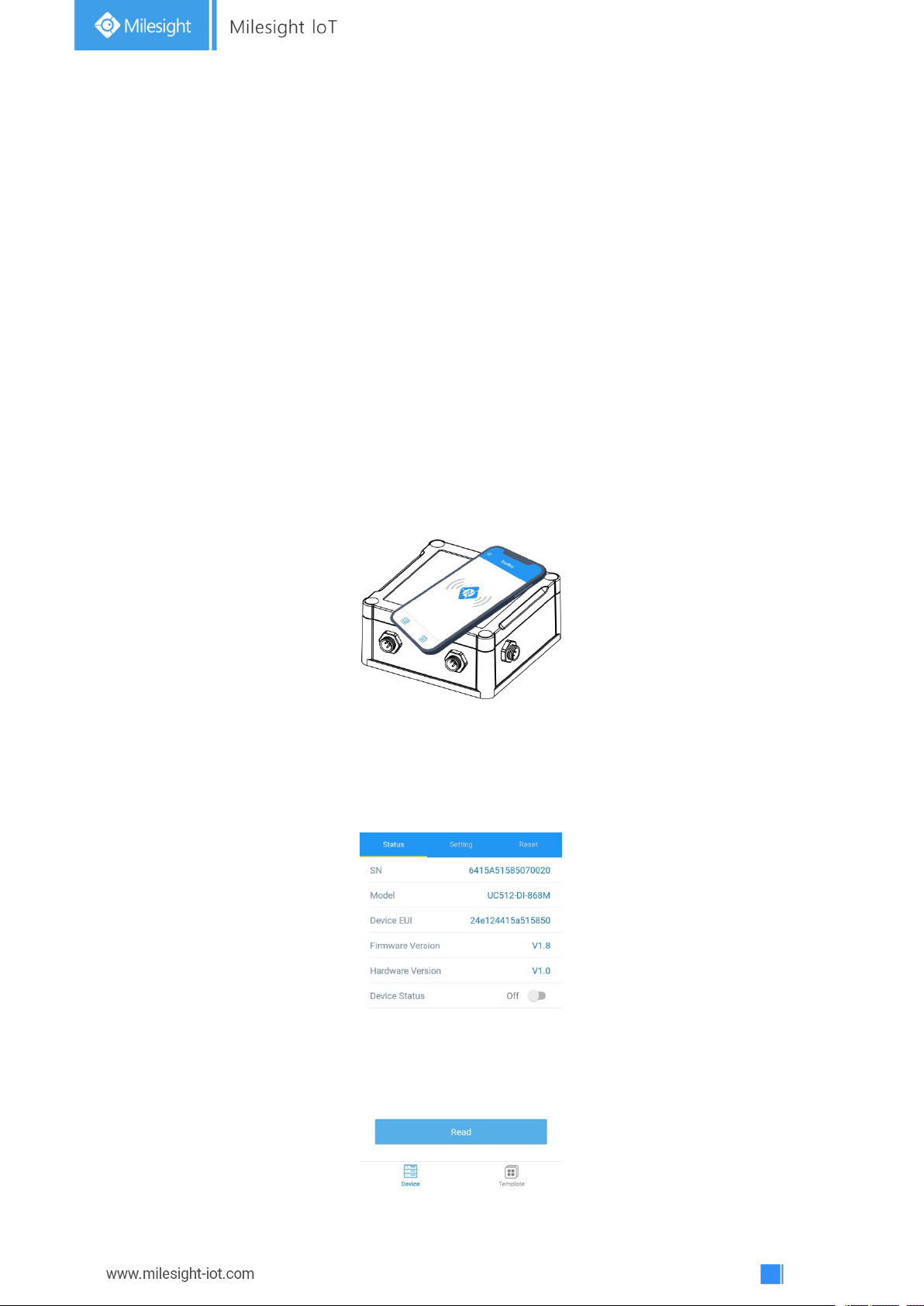
Pole Mounting
Make sure you have wall mounting bracket, bracket mounting screws, hose clamp and other
required tools.
Steps:
1. Mount the enclosure to the mounting bracket with the bracket mounting screws.
2. Loosen the hose clamp by turning the locking mechanism counter-clockwise.
3. Straighten out the hose clamp and slide it through the rectangular holes in the mounting
bracket, wrap the hose clamp around the pole.
4. Use a screwdriver to tighten the locking mechanism by turning it clockwise.
Page 8
8
4. Operation Guide
4.1 Log in the ToolBox
UC51x series can be monitored and configured via ToolBox APP or ToolBox software. Please
select one of them to complete configuration.
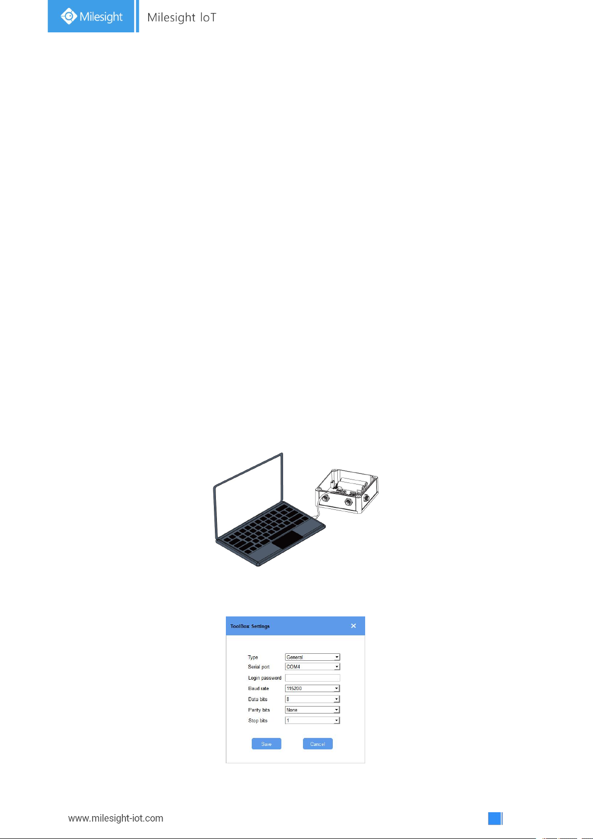
4.1.1 NFC Configuration
Preparation:
Smartphone (NFC supported)
Milesight ToolBox App: V1.3.9 and above
Steps:
1. download and install from Google Play or Apple Store.
2. Enable NFC on the smartphone and open“Milesight ToolBox” APP.
3. Attach the smartphone with NFC area to the device to read basic information.
4. Basic information and settings of devices will be shown on ToolBox if it’s recognized
successfully. You can turn on/off the device by tapping the button on the Device Status. In order
to protect the security of devices, password validation is required when configuring via unused
phone . Default password is 123456.
Page 9
9
5. Tap “Read” button to check current status of device.
6. Tap “Write” button to write all your settings to the device.
Note:
1) Ensure the location of smartphone NFC area and it’s recommended to take off phone case.
2) If the smartphone fails to read/write configurations via NFC, keep the phone away and back
to try again.
3) UC51x series can also be configured by dedicated NFC reader, which can be purchased from
Milesight IoT.
4.1.2 USB Configuration
Preparation:
Type-C USB cable
PC (Windows 10 is recommended)
ToolBox: V6.35 and above
Steps:
1. Download ToolBox from Milesight IoT website.
2. Open the case of UC51x and connect the UC51x to computer via type-C port.
3. Open the ToolBox and select type as “General”, then click password to log in ToolBox.
(Default password: 123456)
Page 10
10
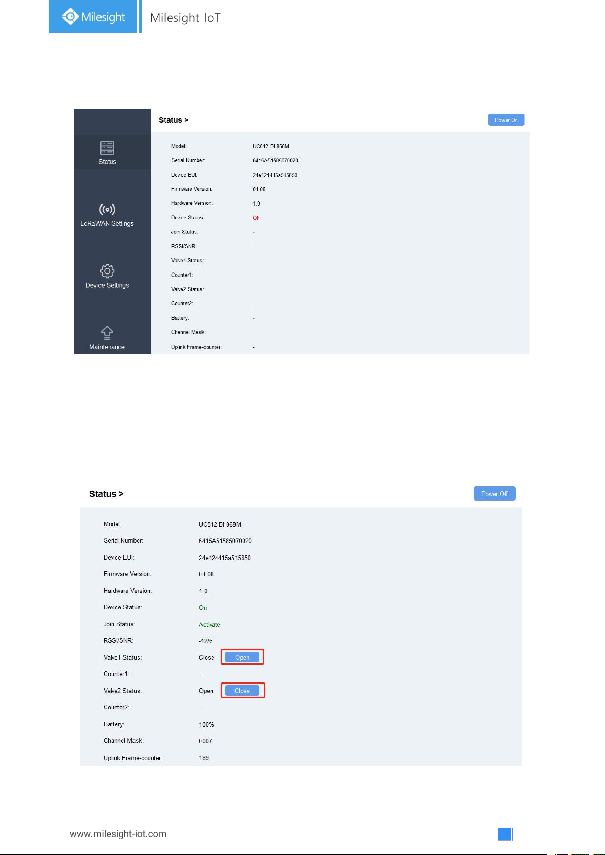
4. After logging in the ToolBox, you can click “Power On” or “Power Off” to turn on/off device
and change other settings.
4.2 Solenoid Valve Control
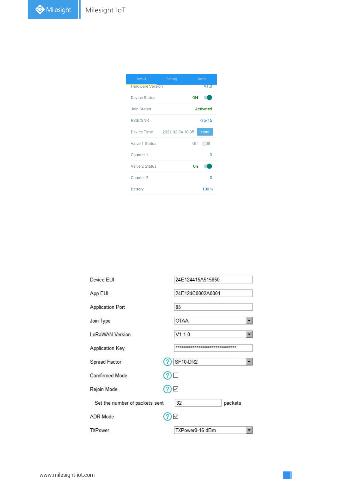
Solenoid valve can be controlled by ToolBox App or ToolBox software locally.
Via ToolBox Software:
Click “Open” or “Close” button on the “Status” page to change the status of solenoid valves.
Page 11
11
Via ToolBox App:
Click buttons of Valve Status on the “Device->Status” page, then attach the smart phone to
device to change the status of solenoid valves.
4.3 LoRaWAN Settings
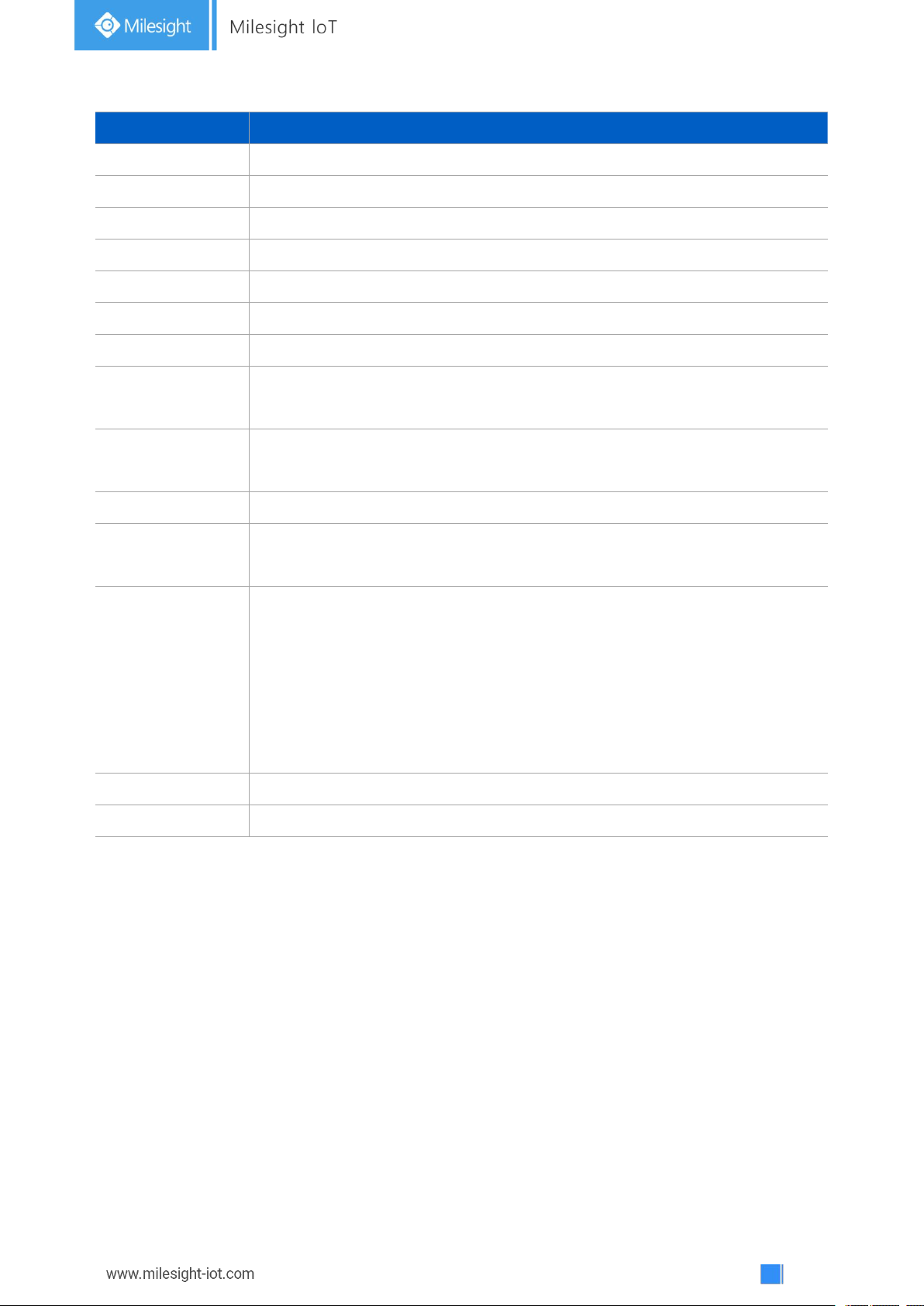
LoRaWAN settings is used for configuring the transmission parameters in LoRaWAN®network.
Step 1: Go to “LoRaWAN -> Basic” of ToolBox software or “Setting->LoRaWAN Settings” of
ToolBox App to configure join type, App EUI, App Key and other information. You can also keep
all settings by default.
Page 12
12
Parameters
Description
Device EUI
Unique ID of the device which can also be found on the label.
App EUI
Default App EUI is 24E124C0002A001.
Application Port
The port used for sending and receiving data, default port is 85.
Join Type
OTAA and ABP mode are available.
LoRaWAN Version
V1.0.2, V1.0.3, V1.1 are available.
Application Key
Appkey for OTAA mode, default is 5572404C696E6B4C6F52613230313823.
Device Address
DevAddr for ABP mode, default is the 5thto 12thdigits of SN.
Network Session
Key
Nwkskey for ABP mode, default is 5572404C696E6B4C6F52613230313823.
Application
Session Key
Appskey for ABP mode, default is 5572404C696E6B4C6F52613230313823.
Spread Factor
If ADR is disabled, the device will send data via this spread factor.
Confirmed Mode
If the device does not receive ACK packet from network server, it will resend
data 3 times at most.
Rejoin Mode
Reporting interval ≤ 30 mins: device will send specific mounts of LoRaMAC
packets to check connection status every 30 mins; If no reply after specific
packets, the device will re-join.
Reporting interval > 30 mins: device will send specific mounts of LoRaMAC
packets every to check connection status every reporting interval; If no reply
after specific packets, the device will re-join.
ADR Mode
Allow network server to adjust datarate of the device.
Tx Power
Based on LoRaWAN®regional parameter document.
Note:
1) Please contact sales for device EUI list if there are many units.
2) Please contact sales if you need random App keys before purchase.
3) Select OTAA mode if you use Milesight IoT cloud to manage devices.
4) Only OTAA mode supports rejoin mode.
5) For TTN connection please select LoRaWAN version as 1.0.2.
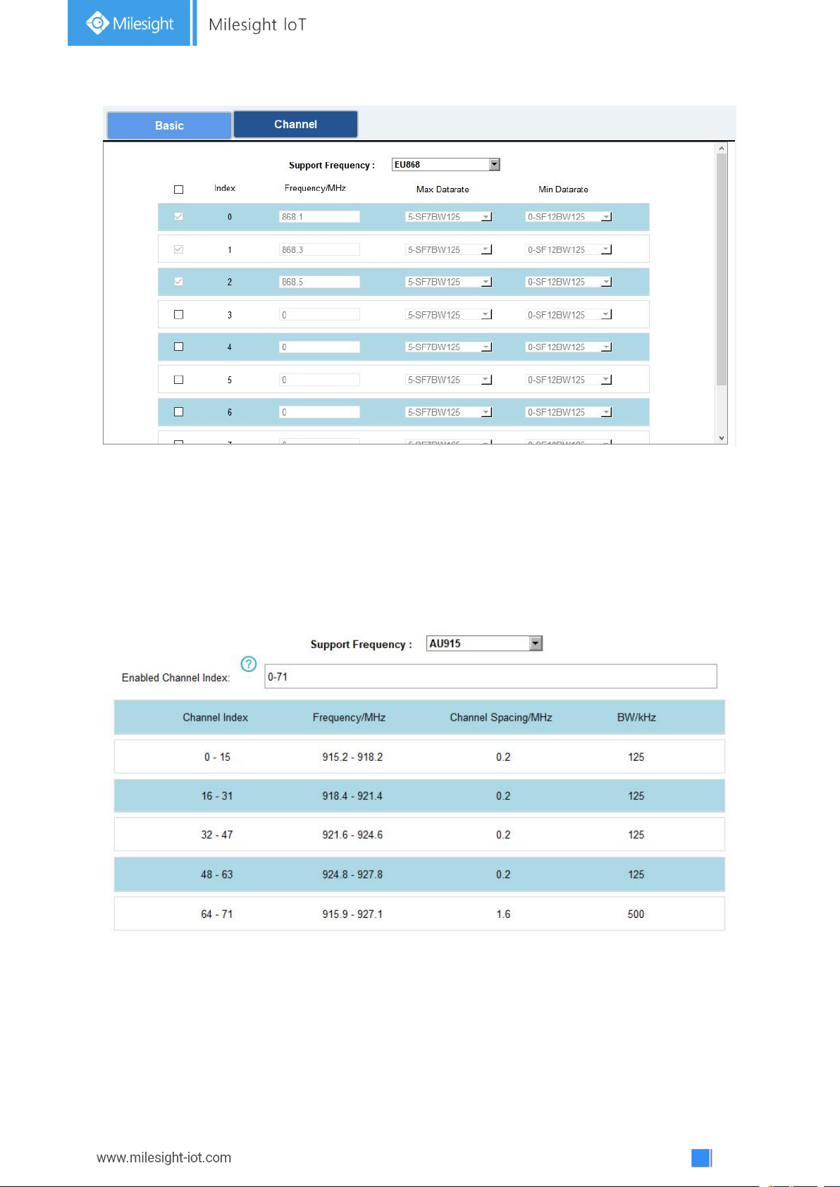
Step 2: Go to “LoRaWAN -> Channel” of ToolBox software or “Setting->LoRaWAN Settings” of
ToolBox APP to select supported frequency and select channels to send uplinks. Make sure the
channels match the LoRaWAN®gateway.
Page 13
13
If frequency is one of CN470/AU915/US915, you can enter the index of the channel that you
want to enable in the input box, making them separated by commas.
Examples:
1, 40: Enabling Channel 1 and Channel 40
1-40: Enabling Channel 1 to Channel 40
1-40, 60: Enabling Channel 1 to Channel 40 and Channel 60
All: Enabling all channels
Null: Indicates that all channels are disabled
Note:
For -868M model, default frequency is EU868;
For -915M model, default frequency is AU915.
Page 14
14
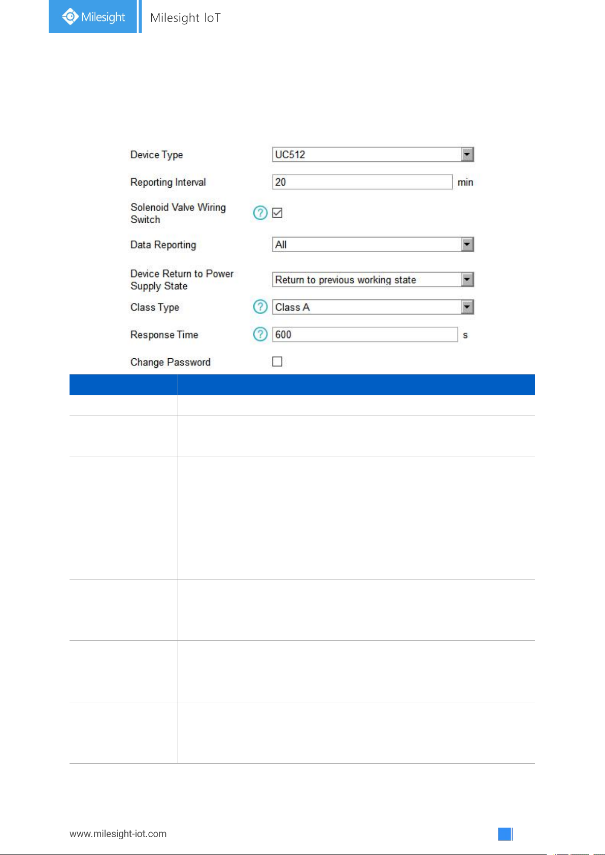
4.4 Solenoid Settings
Parameters
Description
Reporting Interval
Reporting interval of transmitting data to network server.Default: 20min
Solenoid Valve
Wiring Switch
After this parameter is enabled, when users connect the solenoid cable
to any solenoid interface, the device will turn on automatically.
Data Reporting
Select the contents to report to network server.
All: Report all interface status;
Valve 1& Water Meter 1: Report the status of the Valve 1 interface and
data of GPIO1;
Valve 2& Water Meter 2: Report the status of the Valve 2 interface and
data of GPIO2.
Device returns to
the power supply
state
If the device loses power and return to power supply, the device will be
on or off according to this parameter.
Class Type
Working mode of LoRaWAN®device.
UC511: Class A and Class C are available;
UC512: Class A.
Response Time
When the device works under Class A mode, it only receives control
commands every reporting interval comes. In order to shorten the delay
time of control, the device will send blank package to allow to receive the
Go to “General->Device Settings->Basic” of ToolBox software or “Setting->General Settings” of
ToolBox App to change the reporting configurations.
Page 15
15
control commands every Response Time interval.
Note:
The shorter the response time, the shorter the battery life.
Change Password
Change the password for ToolBox App or software to read/write this
device.
Note:
1) When device connects to network server of Milesight gateway, the blank package will take up
the frame count but not show on the package list.
2) The device only starts counting after receiving more than 5 pulses.
3) Reboot or re-join will not affect the counting.
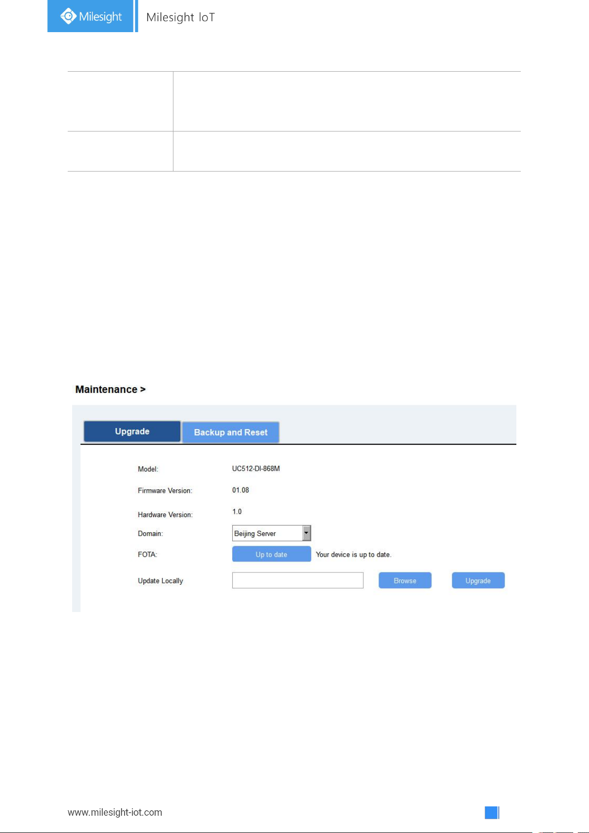
4.5 Maintenance
4.5.1 Upgrade
UC51x series support upgrade locally or over the air only via ToolBox software.
Upgrade Locally:
Step 1: Click “Browse” to import firmware from your computer.
Step 2: Click “Upgrade” to start the upgrade.
Upgrade Over the Air:
Step 1: Select the upgraded server according to your region and make sure your computer can
access the Internet.
Step 2: Click “Up to date” to search for latest firmware of devices. If your firmware is latest
version, ToolBox will prompt “Your device is up to date”.
Page 16
16
Note: Any operation on ToolBox is not allowed during upgrading, otherwise the upgrading will be
interrupted, or even the device will break down.
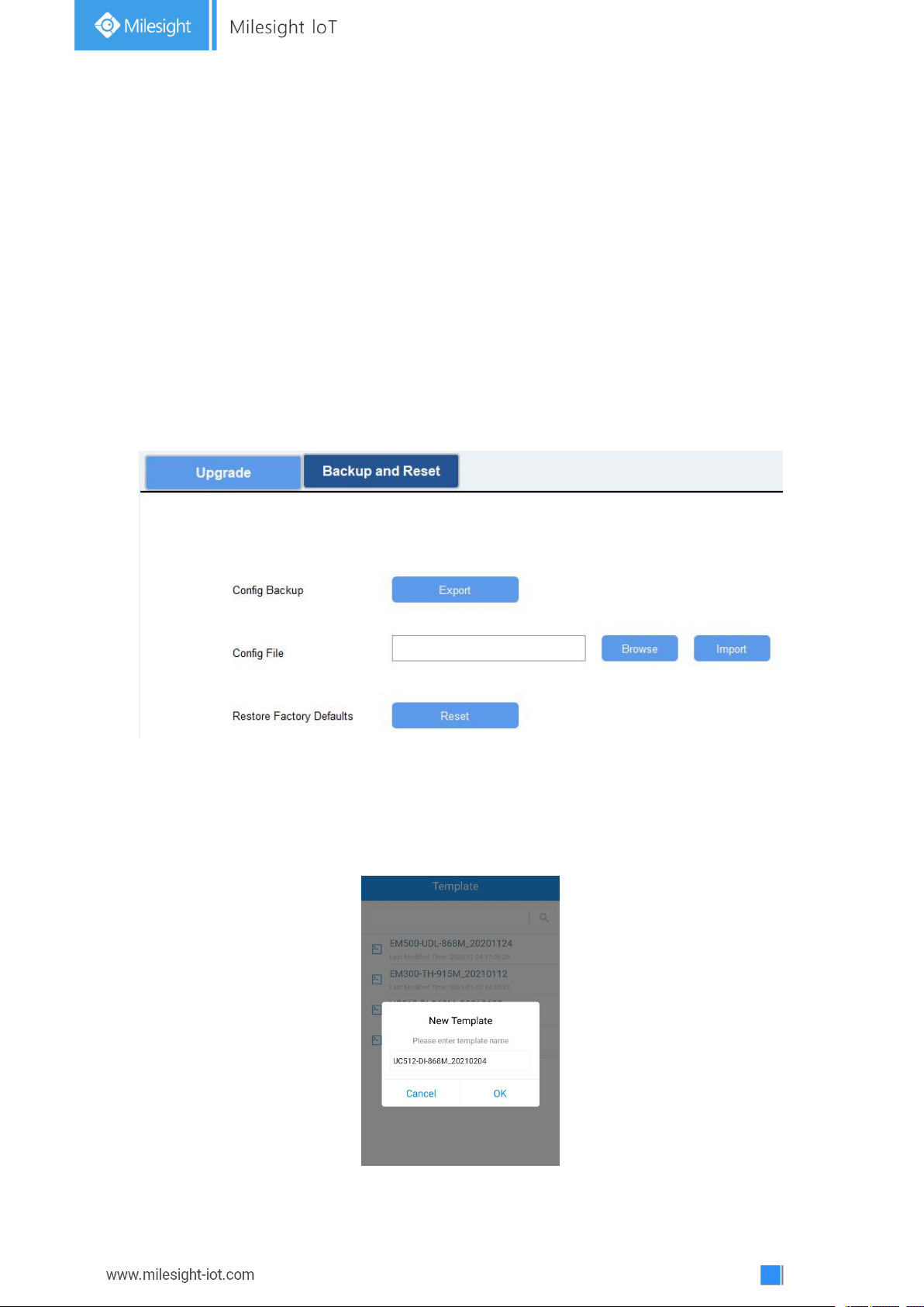
4.5.2 Backup
UC51x devices support configuration backup for easy and quick device configuration in bulk.
Backup is allowed only for devices with the same model and LoRa frequency band. Please select
one of following methods to backup device:
Via ToolBox Software
Step 1: Go to “Maintenance->Backup and Reset”, click “Export” to save current configuration as
json format backup file.
Step 2: Click “Browse” to select backup file, then click “Import” to import the configurations.
Via ToolBox APP
Step 1: Go to “Template” page on the APP and save current settings as a template. You can also
edit the template file.
Step 2: Select this template and attach to another device to write configuration.
Page 17
17
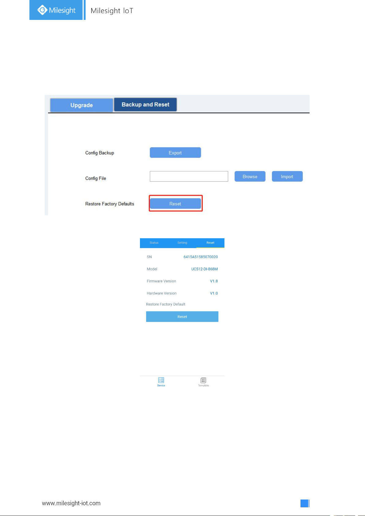
4.5.3 Reset to Factory Default
Please select one of following methods to reset device:
Via Hardware: Open the case of UC51x and hold on power button more than 10s.
Via ToolBox Software: Go to “Maintenance->Backup and Reset” to click “Reset”.
Via ToolBox APP: Go to “Device->Reset” to click “Reset”, then attach smart phone with NFC area
to UC51x to complete reset.
Page 18
18
5. Milesight IoT Cloud Management
UC51x series can be managed by Milesight IoT Cloud platform. Milesight IoT cloud is a
comprehensive platform that provides multiple services including device remote management
and data visualization with the easiest operation procedures. Please register a Milesight IoT
Cloud account before operating following steps.
5.1 Add a Milesight Gateway
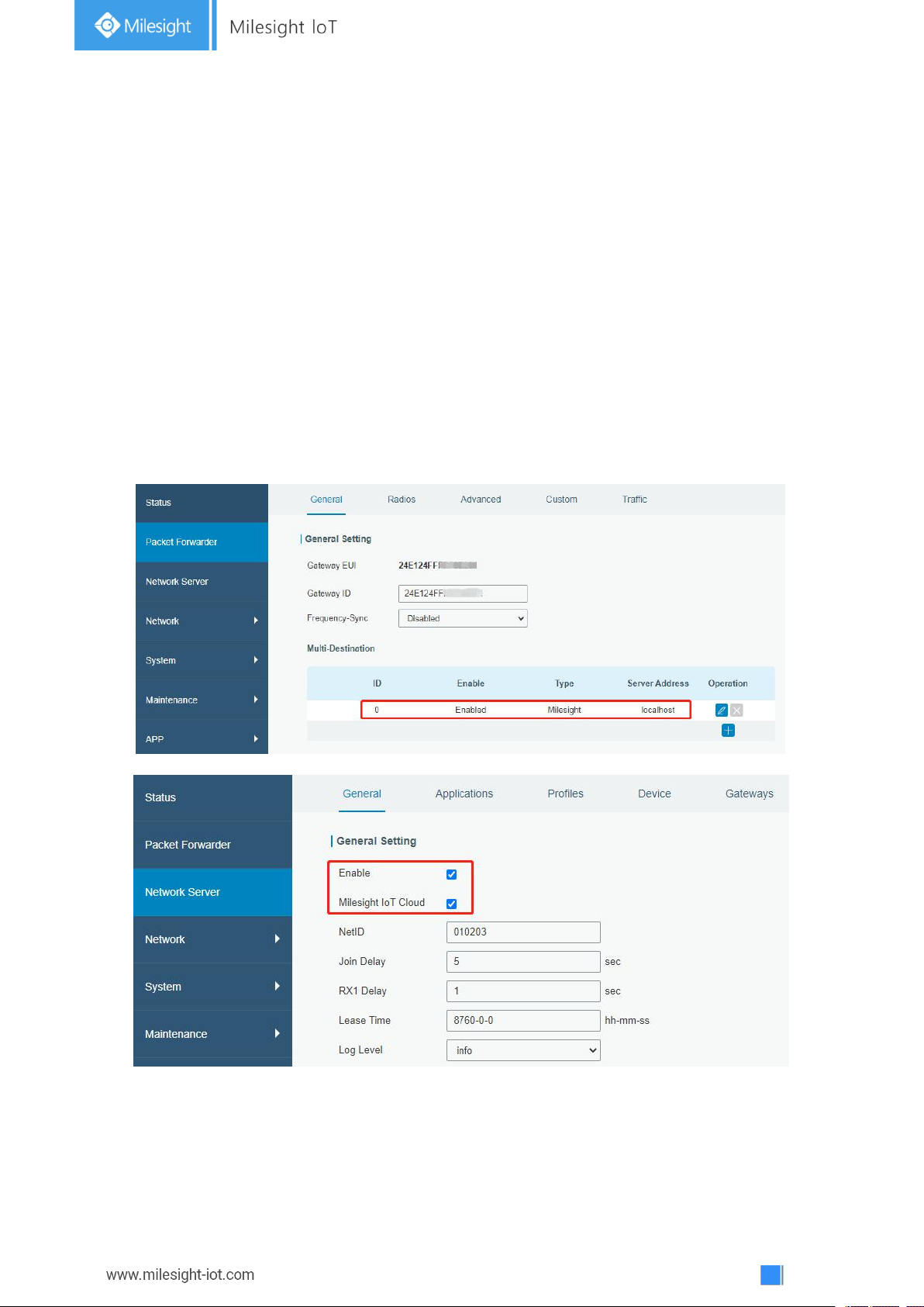
Step 1: Enable “Milesight” type network server and “Milesight IoT Cloud” mode in gateway web
GUI.
Note: Ensure gateway has accessed the Internet.
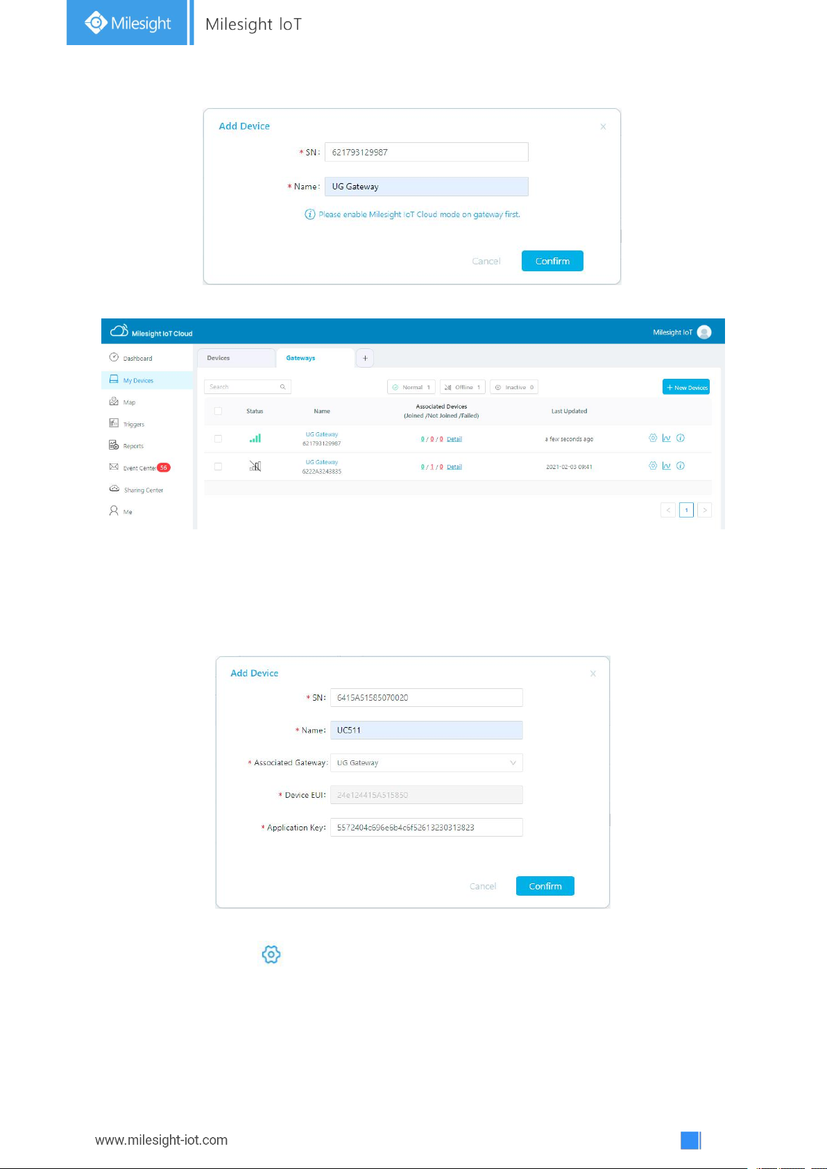
Step 2: Go to “My Devices” page and click “+New Devices” to add gateway to Milesight IoT Cloud
via SN. Gateway will be added under “Gateways” menu.
Page 19
19
Step 3: Check if gateway is online in Milesight IoT Cloud.
5.2 Add UC51x to Milesight IoT Cloud
Step 1: Go to “My Devices” page and click “+New Devices”. Fill in the SN of UC51x and select
associated gateway.
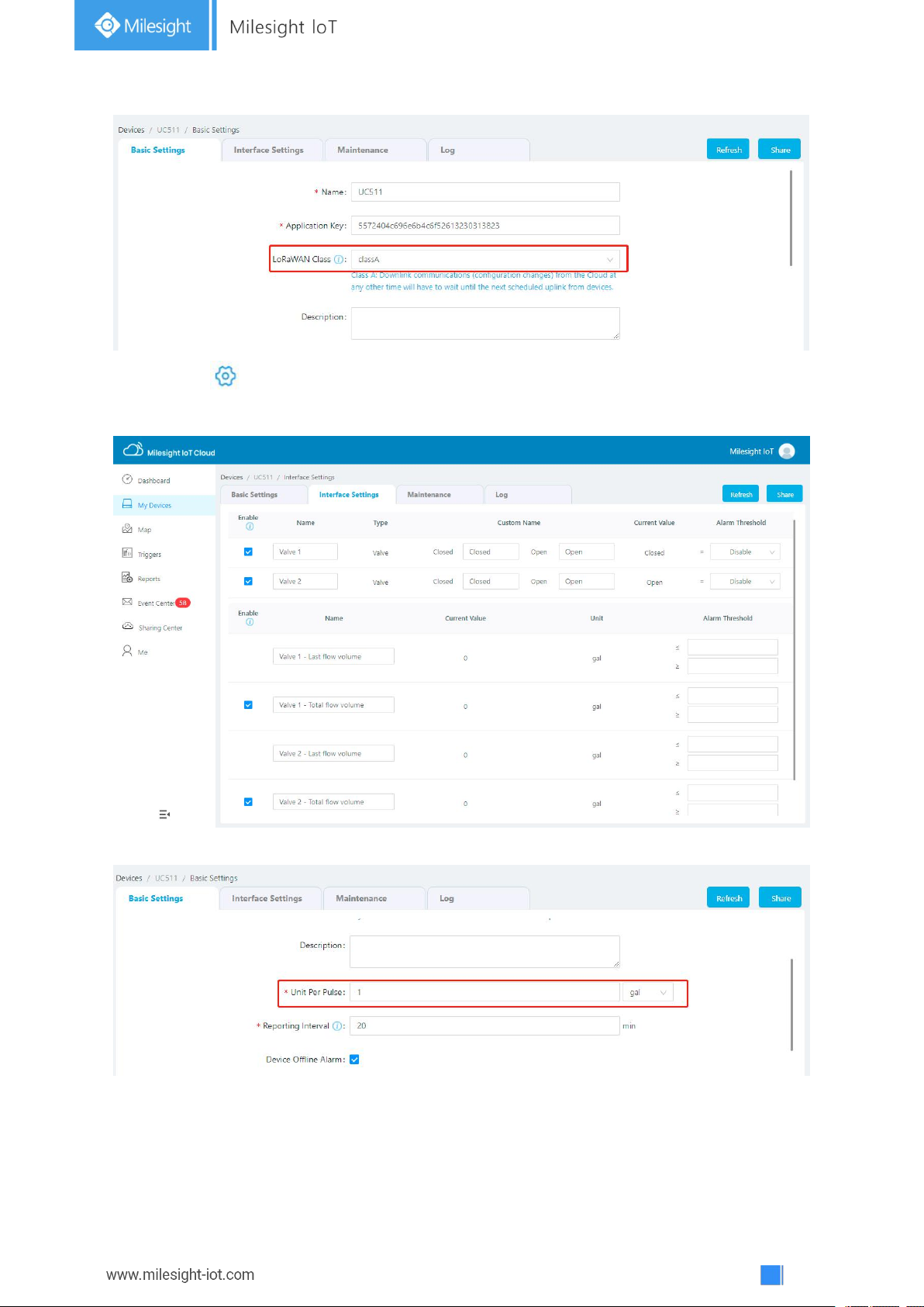
Step 2: Default working mode of UC511 devices is Class C. If you need to change the mode of
UC511 to Class A, click and go to “Basic Settings” to change mode to Class A.
Page 20
20
Step 3: Click and go to “Interface Settings” to select used interfaces and customize the
name and thresholds.
Besides, go to “Basic Settings” to configure the unit of per pulse if you connect the water meter.
Page 21
21
5.3 Solenoid Valve Control
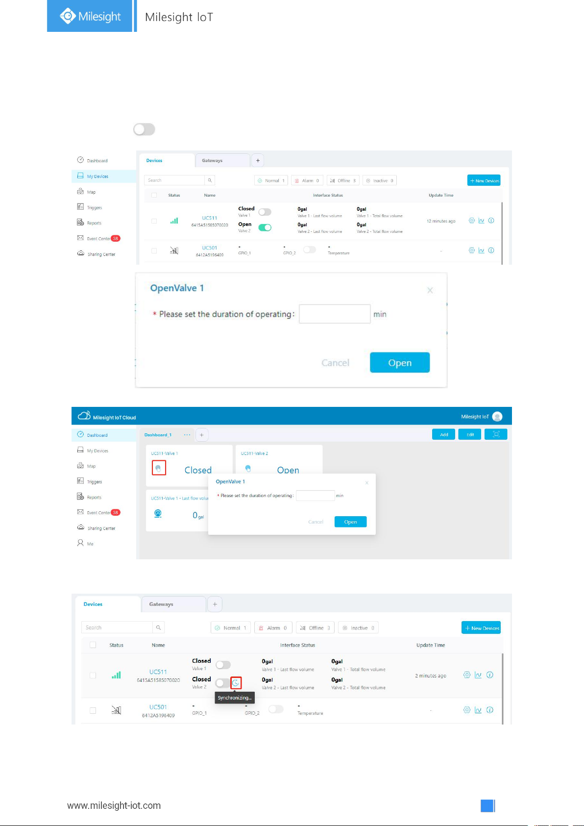
Solenoid valve can be controlled by Milesight IoT cloud webpage or App.
Step 1: Click to open the solenoid valve and configure the duration.
You can also add a switch on the dashboard to control the status of solenoid valves.
Note: If working mode of UC51x is Class A, control commands will delay until the time icon
disappear.
Page 22
22
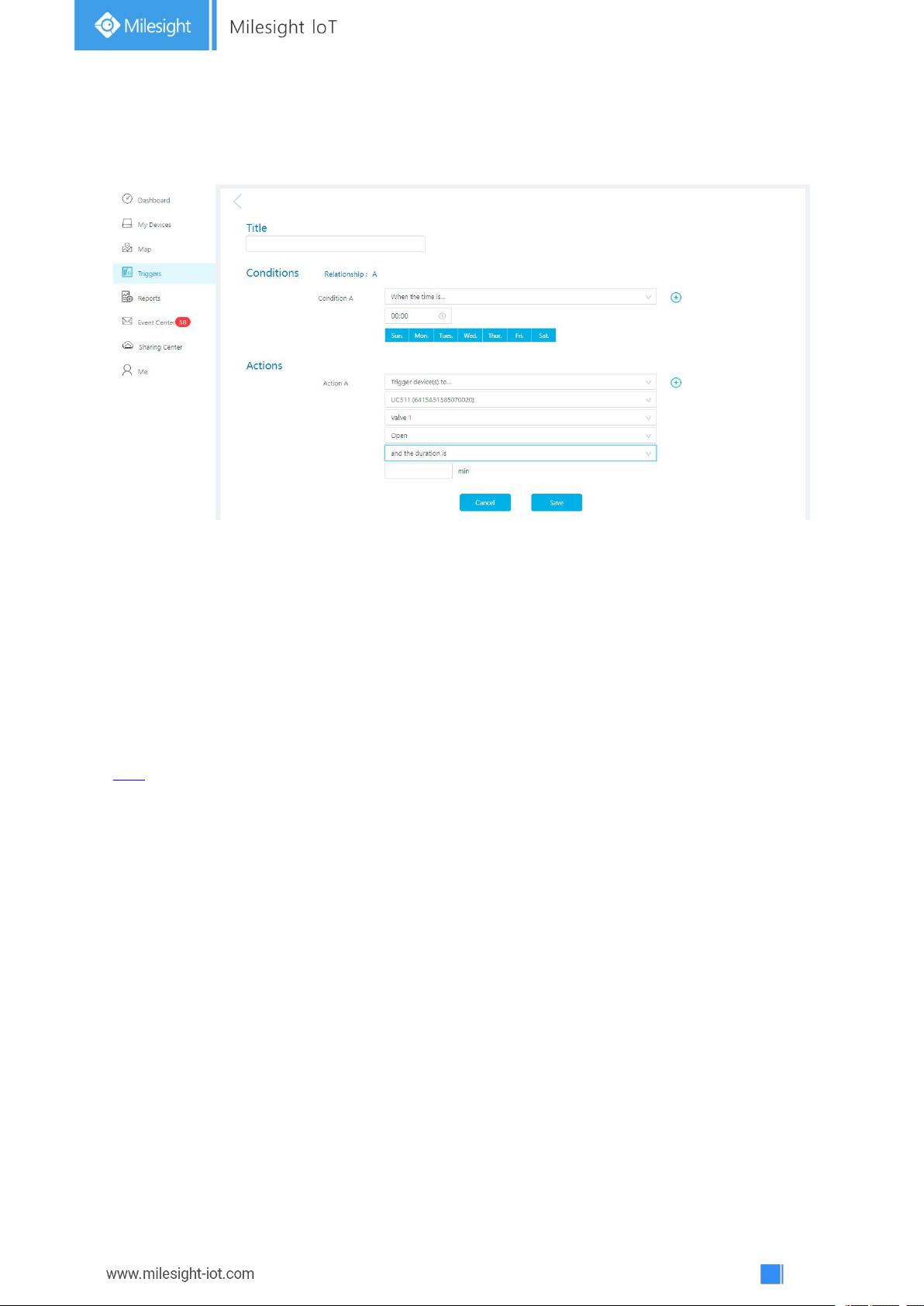
Step 2: Go to “Triggers” page to add actions to trigger the solenoid valve to open for a period of
time or a specific volume of water.
Note: Water volume control is only worked when you connect water meter to UC51x device.
6. Device Payload
UC51x Series use the standard Milesight IoT payload format based on IPSO. Please refer to the
UC51x Series Communication Protocol
here.
; for decoders of Milesight IoT products please click
-END-
 Loading...