

Page 1

Milesight IoT
AM100 Series
User Guide
Page 2
2
Applicability
Model
Description
AM104
Indoor Ambiance Sensor(Temp, Hum, Light, Motion)
AM107
Indoor Ambiance Sensor(Temp, Hum, Light, Motion, CO2, TVOC, Pressure)
This guide is applicable to AM100 series sensors shown as follows, except where otherwise
indicated.
Safety Precautions
Milesight will not shoulder responsibility for any loss or damage resulting from not following the
instructions of this operating guide.
The device must not be disassembled or remodeled in any way.
Do not place the device outdoors where the temperature is below/above operating range.
Do not place the device close to objects with naked flames, heat source (oven or sunlight),
cold source, liquid and extreme temperature changes.
The device is not intended to be used as a reference sensor, and Milesight will not should
responsibility for any damage which may result from inaccurate readings.
The battery should be removed from the device if it is not to be used for an extended period.
Otherwise, the battery might leak and damage the device. Never leave a discharged battery
in the battery compartment.
The device must never be subjected to shocks or impacts.
Do not clean the device with detergents or solvents such as benzene or alcohol. To clean
the device, wipe with a soft moistened cloth. Use another soft, dry cloth to wipe dry.
Declaration of Conformity
AM100 series is in conformity with the essential requirements and other relevant provisions of
the CE, FCC, and RoHS.
Copyright © 2011-2021 Milesight. All rights reserved.
All information in this guide is protected by copyright law. Whereby, no organization or individual
shall copy or reproduce the whole or part of this user guide by any means without written
authorization from Xiamen Milesight IoT Co., Ltd.
Page 3
3
Revision History
Date
Doc Version
Description
Apr. 7, 2020
V 1.0
Initial version
May 19, 2020
V 1.1
App pictures replacement
Aug. 26, 2020
V 1.2
Add screen display mode and configuration examples
Sept.14, 2020
V 1.3
Add screen alarm settings
Nov. 19, 2020
V 2.0
Layout replace
Mar. 2, 2021
V 2.1
Change model from AM100/AM102 to AM104/AM107
For assistance, please contact
Milesight technical support:
Email: [email protected]
Tel: 86-592-5085280
Fax: 86-592-5023065
Address: 4/F, No.63-2 Wanghai Road,
2ndSoftware Park, Xiamen, China
Page 4
4
Contents
1. Product Introduction
1.1 Overview
1.2 Features
2. Hardware Introduction
2.1 Packing List
2.2 Hardware Overview
2.3 E-link Screen
2.3.1 Screen Description
2.3.2 Screen Mode Switch
2.4 Power Button
2.5 Dimensions(mm)
3. Power Supply
4. Operation Guide
4.1 Log in the ToolBox
4.1.1 NFC Configuration
4.1.2 USB Configuration
4.2 LoRaWAN Settings
4.3 Time Synchronization
4.4 Basic Settings
4.5 Advanced Settings
4.5.1 Data Collection Settings
4.5.2 Calibration Settings
4.5.3 Threshold Settings
4.6 Maintenance
4.6.1 Upgrade
4.6.2 Backup
4.6.3 Reset to Factory Default
5. Installation
5.1 Installation Note
5.2 Wall Mounting
6. Milesight IoT Cloud Management
6.1 Add a Milesight Gateway
6.2 Add AM104/AM107 to Milesight IoT Cloud
7. Device Payload
7.1 Basic Information
7.2 Sensor Data
7.3 Downlink Commands
Appendix
.......................................................................................................................................................
Carbon Dioxide Levels and Guidelines
.............................................................................................................................................
................................................................................................................................................
.................................................................................................................................
...........................................................................................................................................
............................................................................................................................................
..............................................................................................................................
......................................................................................................................................
.........................................................................................................................
....................................................................................................................................
..............................................................................................................
...........................................................................................................
...................................................................................................................................
............................................................................................................................
.........................................................................................................................................
..........................................................................................................................
...............................................................................................................
.............................................................................................................
.......................................................................................................................
...................................................................................................................
................................................................................................................................
........................................................................................................................
...................................................................................................
...........................................................................................................
............................................................................................................
..................................................................................................................................
...............................................................................................................................
.................................................................................................................................
...................................................................................................
............................................................................................................................
................................................................................................................................
........................................................................................................
.............................................................................................................
........................................................................................................................................
..........................................................................................................................
....................................................................................................................................
...................................................................................................................
.............................................................................
.............................................................................................
5
5
5
5
5
6
6
6
8
8
8
9
9
9
9
11
12
15
16
16
16
17
18
18
18
19
20
21
21
22
22
22
24
25
25
25
26
26
26
Page 5
5
1. Product Introduction
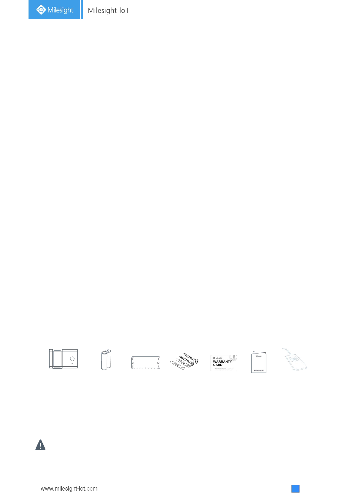
1 ×
AM104/AM107
2 ×
AA
Batteries
(LR6)
1 ×
Mounting
Sticker
2 ×
Mounting
Screws
1 ×
Warranty
Card
1 ×
Quick
Guide
1 ×
NFC Reader
(Optional)
If any of the above items is missing or damaged, please contact your sales Representative.
1.1 Overview
AM100 series is a compact indoor ambience monitoring sensor including motion, humidity,
temperature, light, TVOC, CO2, barometric pressure for wireless LoRa network. AM100 series is a
battery powered device and is designed to be wall-mounted. It is equipped with NFC (Near Field
Communication) and can easily be configured via a smartphone or a PC software.
Sensor data are transmitted in real-time using standard LoRaWAN®protocol. LoRaWAN
enables encrypted radio transmissions over long distance while consuming very little power. The
user can obtain sensor data and view the trend of data change through Milesight IoT Cloud or
through the user's own Network Server.
1.2 Features
Robust LoRa connectivity for indoor or HVAC environments
Integrated multiple sensors like temperature, humidity, light, air quality, etc.
®
Easy configuration via NFC
Visual display via E-Ink screen
Standard LoRaWAN®support
Milesight IoT Cloud compliant
Low power consumption (about 1 year battery life)
Standard AA alkaline battery
2. Hardware Introduction
2.1 Packing List
Page 6
6
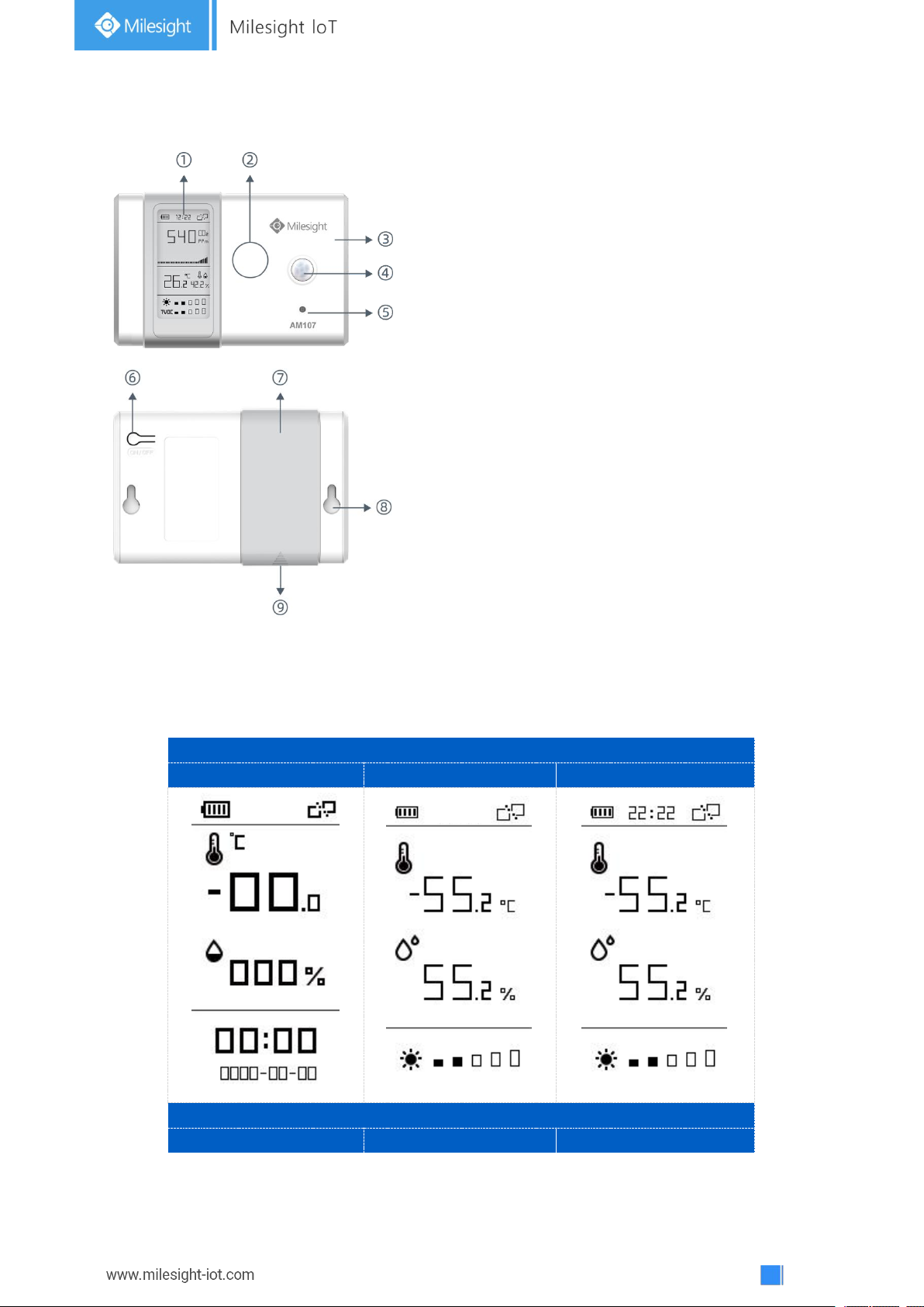
2.2 Hardware Overview
AM104
Mode 1
Mode 2
Mode 3
AM107
Mode 1
Mode 2
Mode 3
Front Panel:
①E-ink screen
② NFC Area
③ LoRa Antenna (Internal)
④PIR Sensor
⑤Light Sensor
Back Panel:
⑥Power button
⑦Battery Cover
⑧Mounting Holes
⑨Type-C Port
2.3 E-link Screen
2.3.1 Screen Description
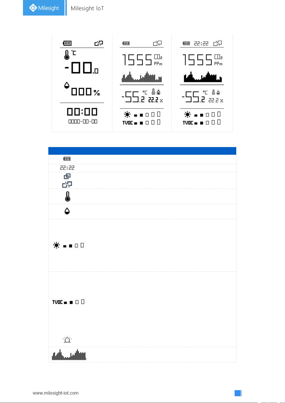
AM100 series provide 3 types of display modes:
Page 7
7
To learn what an icon means, find it below.
Icon
Description
Screen Update
Battery level
24 hours
Sync time with software or mobile App
1 min
The device joins the network.
According to
join status
The device fails to join the network.
Temperature
1 min
Humidity
1 min
Luminance
Level 0:0-5 lux
Level 1:6-50 lux
Level 2:51-100 lux
Level 3:101-400 lux
Level 4:401-700 lux
Level 5:≥701 lux
1 min
Total volatile organic compounds
Level 0:0-100 ppb
Level 1:101-200 ppb
Level 2:201-250 ppb
Level 3:251-300 ppb
Level 4:301-350 ppb
Level 5:351-400 ppb
1 min
Show alarm when TVOC exceeds the
threshold value.(400 ppb by default)
Show CO2history tendency from 0 to
1400ppm.
2 min
Page 8
8
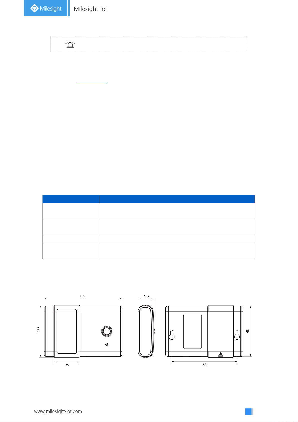
Show alarm when CO2exceeds the threshold
value.(1200 ppm by default)
Note:
Function
Action
Turn On
Press and hold the power button for more than 3 seconds until
the screen changes state.
Turn Off
Press and hold the power button for more than 3 seconds until
the screen changes state.
Reset
Press and hold the power button for more than 10 seconds.
Change Screen Mode
Quick press the power button.
AM100 series will do a full-screen refresh every 30 minutes in order to remove ghosting.
Please refer section 4.5.3 for TVOC and CO2threshold settings.
AM100 series shows current value on the screen and uplink the average value of the
reporting interval to the gateway.
2.3.2 Screen Mode Switch
Here are 3 methods to switch between the three modes:
Power button: Quick press the power button to switch the mode.
Mobile App: Go to Milesight ToolBox App menu “Device > Setting > General Settings” to
select screen display mode.
Software: Go to Toolbox menu “Device Settings > Basic > Basic Settings” to select screen
display mode.
2.4 Power Button
AM100 series can be turned on/off or reset by power button on the rear panel.
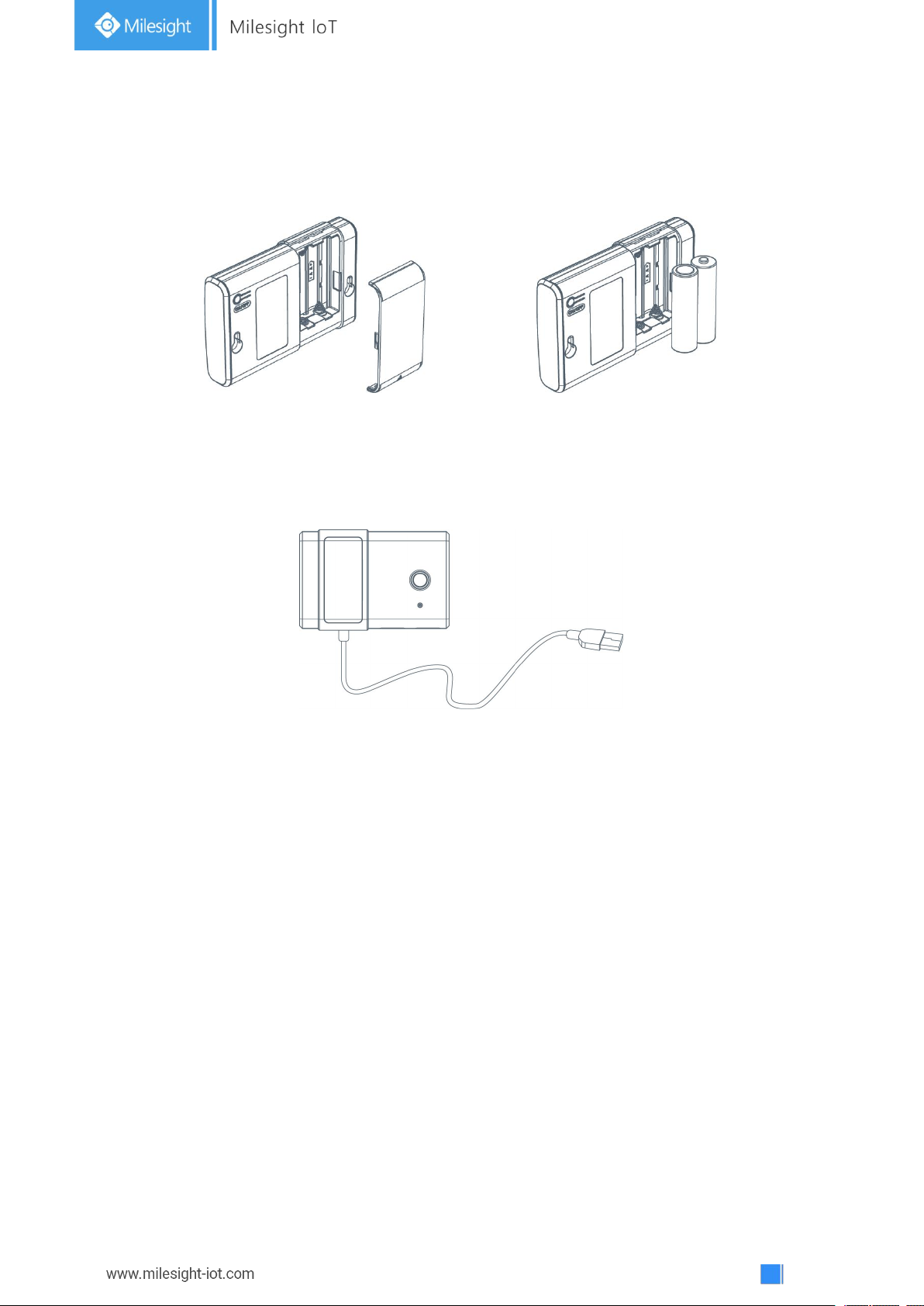
2.5 Dimensions(mm)
Page 9
9
3. Power Supply
Remove the battery cover and install two new AA/LR6 batteries. Batteries can be replaced on the
fly.
Note:
AM100 series can also be powered by type-C USB port (5V, 100mA). When batteries and
external power are both connected, external power will power the device first.
USB port can't be used to charge battery.
4. Operation Guide
4.1 Log in the ToolBox
AM100 series can be monitored and configured via ToolBox App or ToolBox software. Please
select one of them to complete configuration.
4.1.1 NFC Configuration
Preparation:
Smartphone (NFC supported)
Milesight ToolBox App
Steps:
1. Download and install from Google Play or Apple Store.
2. Enable NFC on the smartphone and open“Milesight ToolBox” App.
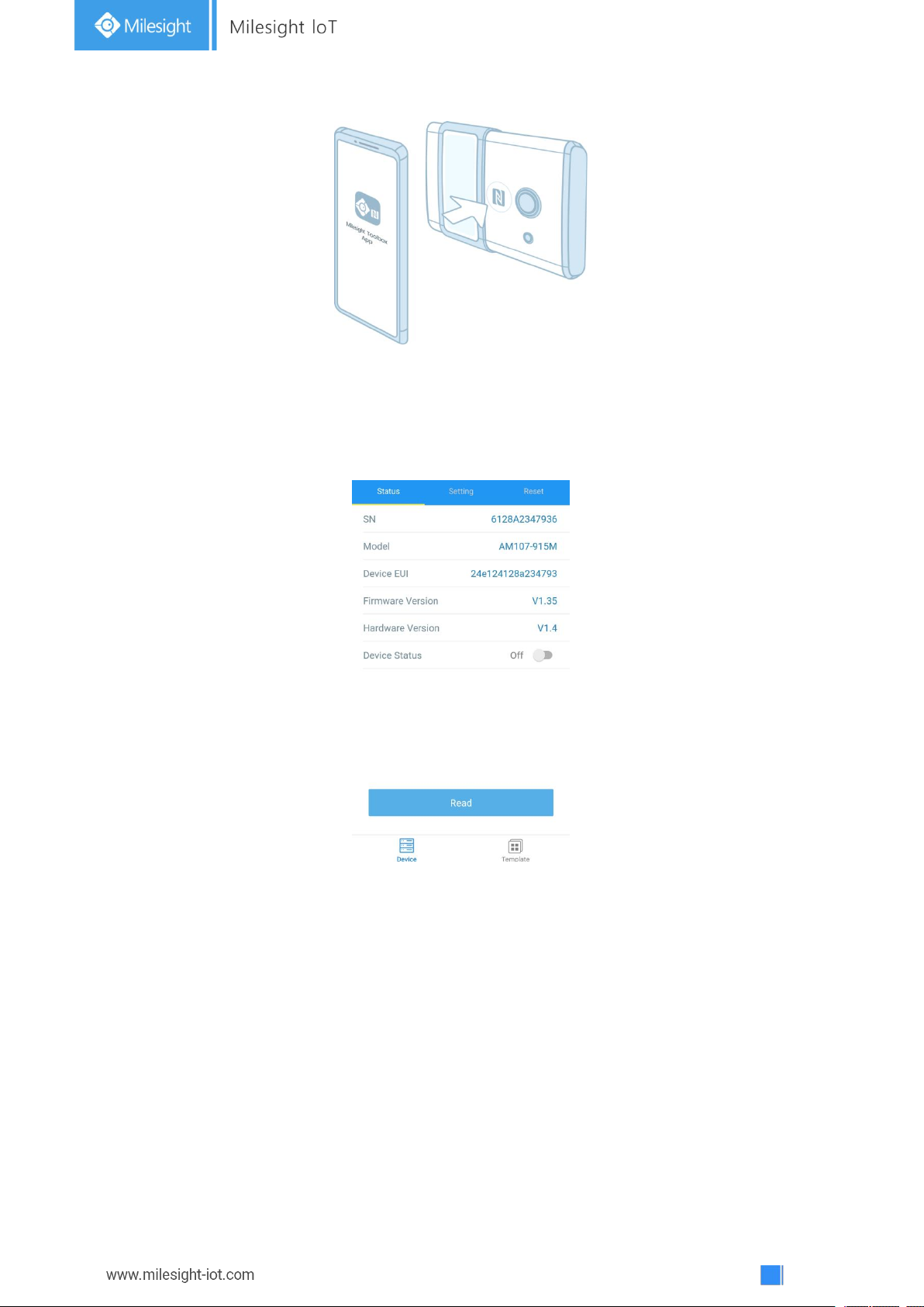
3. Attach the smartphone with NFC area to the device to read basic information.
Page 10
10
4. Basic information and settings of devices will be shown on ToolBox if it’s recognized
successfully. You can turn on/off the device by tapping the button on the Device Status. In order
to protect the security of devices, password validation is required when configuring via unused
phone . Default password is 123456.
5. Tap “Read” button to check current status and sensor data of device.
6. Tap “Write” button to write all your settings to the device.
Note:
1) Ensure the location of smartphone NFC area and it’s recommended to take off phone case.
2) If the smartphone fails to read/write configurations via NFC, keep the phone away and back
to try again.
3) AM100 series can also be configured by dedicated NFC reader, which can be purchased from
Milesight IoT.
Page 11
11
4.1.2 USB Configuration
Preparation:
Type-C USB cable
PC (Windows 10 is recommended)
ToolBox: V6.8 and above
Steps:
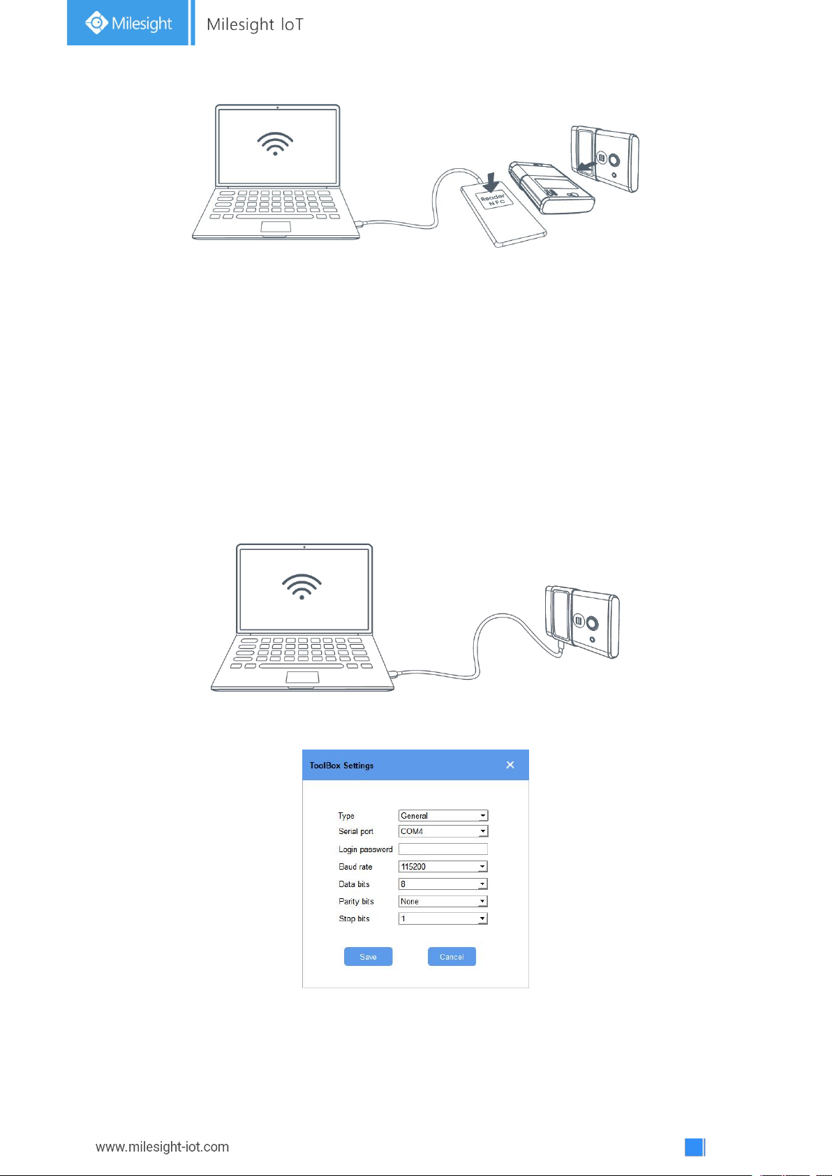
1. Download ToolBox from Milesight IoT website.
2. Connect the device to computer via type-C port.
3. Open the ToolBox and select type as “General”, then click password to log in ToolBox.
(Default password: 123456)
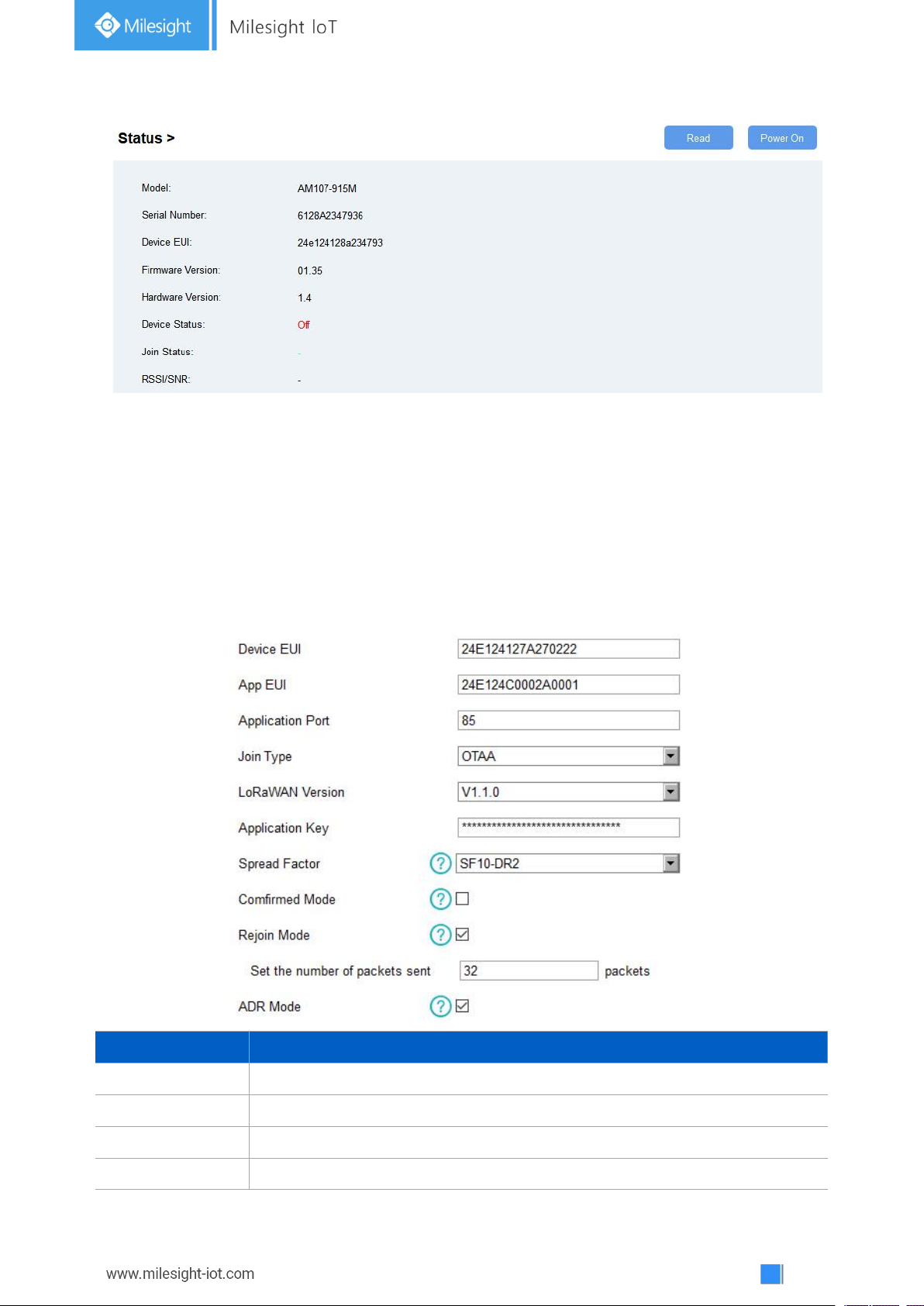
4. After logging in the ToolBox, you can click “Power On” or “Power Off” to turn on/off device
and change other settings.
Page 12
12
4.2 LoRaWAN Settings
Parameters
Description
Device EUI
Unique ID of the device which can also be found on the label.
App EUI
Default App EUI is 24E124C0002A001.
Application Port
The port used for sending and receiving data, default port is 85.
Join Type
OTAA and ABP mode are available.
LoRaWAN settings is used for configuring the transmission parameters in LoRaWAN®network.
Step 1: Go to “LoRaWAN Settings -> Basic” of ToolBox software or “Device->Setting->LoRaWAN
Settings” of ToolBox App to configure join type, App EUI, App Key and other information. You
can also keep all settings by default.
Page 13
13
LoRaWAN Version
V1.0.2, V1.0.3, V1.1 are available.
Application Key
Appkey for OTAA mode, default is 5572404C696E6B4C6F52613230313823.
Device Address
DevAddr for ABP mode, default is the 5thto 12thdigits of SN.
Network Session
Key
Nwkskey for ABP mode, default is 5572404C696E6B4C6F52613230313823.
Application
Session Key
Appskey for ABP mode, default is 5572404C696E6B4C6F52613230313823.
Spread Factor
If ADR is disabled, the device will send data via this spread factor.
Confirmed Mode
If the device does not receive ACK packet from network server, it will resend
data 3 times at most.
Rejoin Mode
Reporting interval ≤ 30 mins: device will send specific mounts of LoRaMAC
packets to check connection status every 30 mins; If no reply after specific
packets, the device will re-join.
Reporting interval > 30 mins: device will send specific mounts of LoRaMAC
packets every to check connection status every reporting interval; If no reply
after specific packets, the device will re-join.
ADR Mode
Allow network server to adjust datarate of the device.
Tx Power
Based on LoRaWAN®regional parameter document.
Note:
1) Please contact sales for device EUI list if there are many units.
2) Please contact sales if you need random App keys before purchase.
3) Select OTAA mode if you use Milesight IoT cloud to manage devices.
4) Only OTAA mode supports rejoin mode.
5) For TTN connection please select LoRaWAN version as 1.0.2.
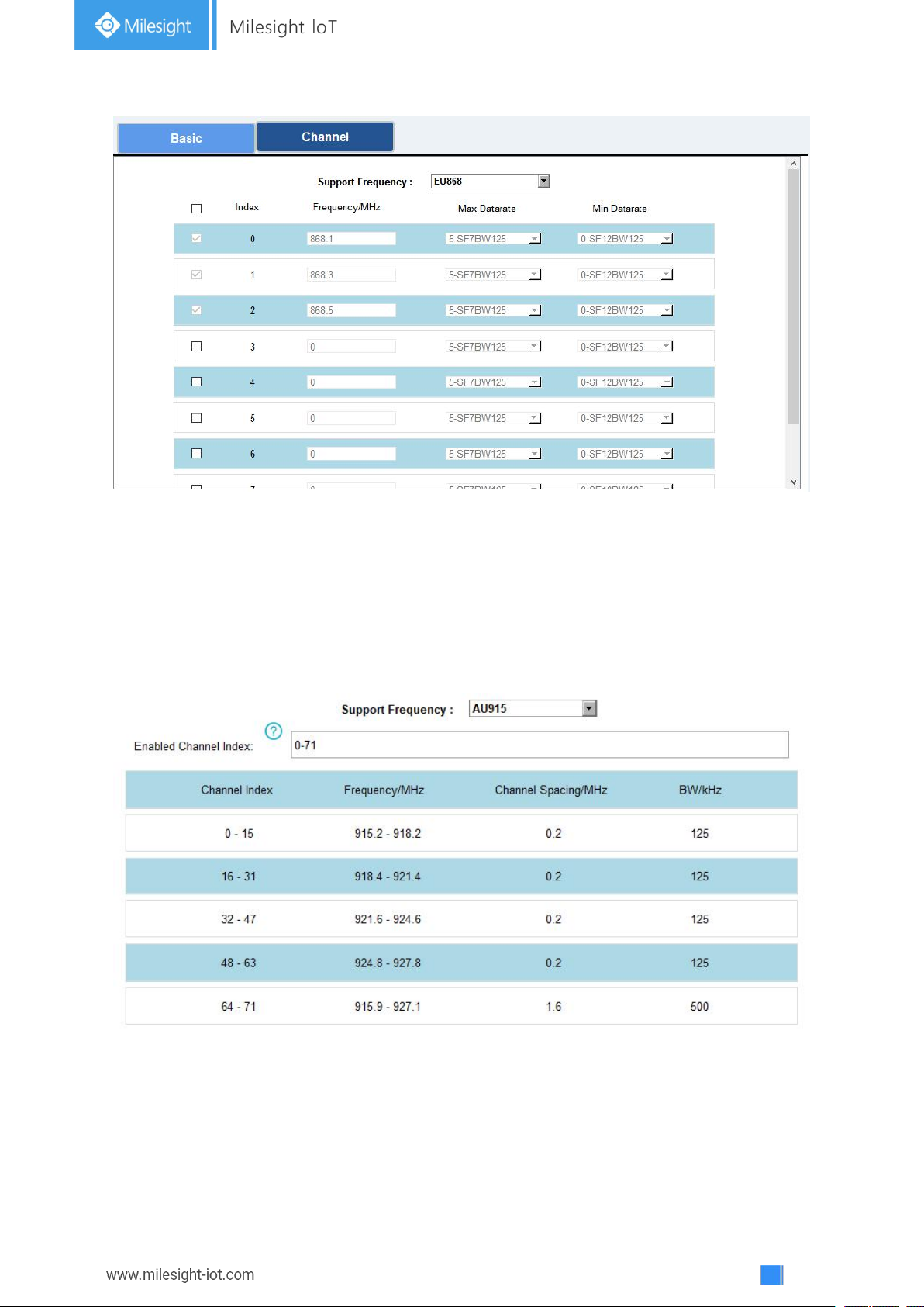
Step 2: Go to “LoRaWAN -> Channel” of ToolBox software or “Setting->LoRaWAN Settings” of
ToolBox App to select supported frequency and select channels to send uplinks. Make sure the
channels match the LoRaWAN®gateway.
Page 14
14
If frequency is one of CN470/AU915/US915, you can enter the index of the channel that you
want to enable in the input box, making them separated by commas.
Examples:
1, 40: Enabling Channel 1 and Channel 40
1-40: Enabling Channel 1 to Channel 40
1-40, 60: Enabling Channel 1 to Channel 40 and Channel 60
All: Enabling all channels
Null: Indicates that all channels are disabled
Note:
For -868M model, default frequency is EU868;
For -915M model, default frequency is AU915.
Page 15
15
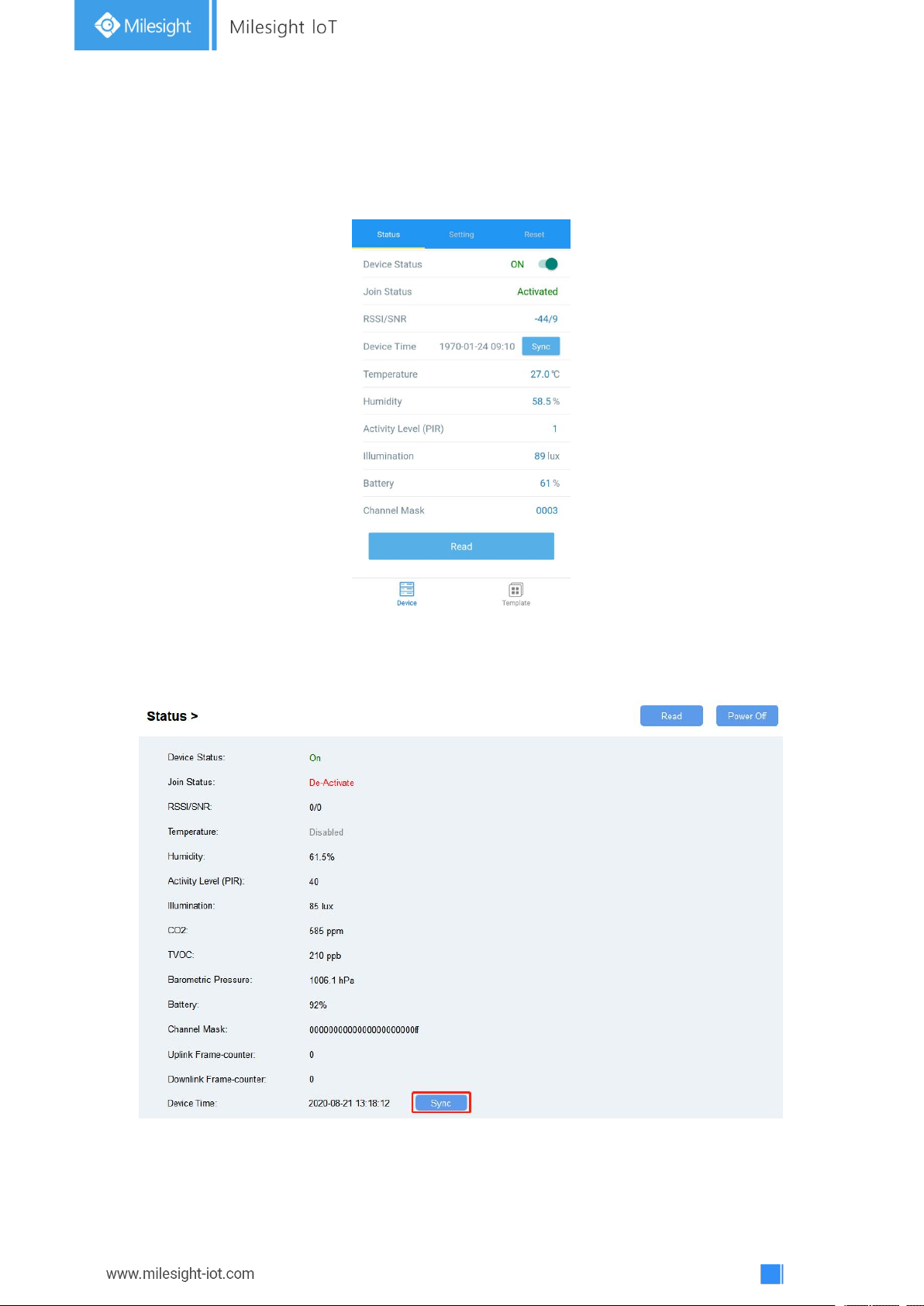
4.3 Time Synchronization
Mobile App Configuration:
Open Toolbox App and go to “Device ->Status”to click “sync” to sync the time on the screen.
Software Configuration:
Log in Toolbox and go to “Status” page to sync the time on the screen.
Page 16
16
4.4 Basic Settings
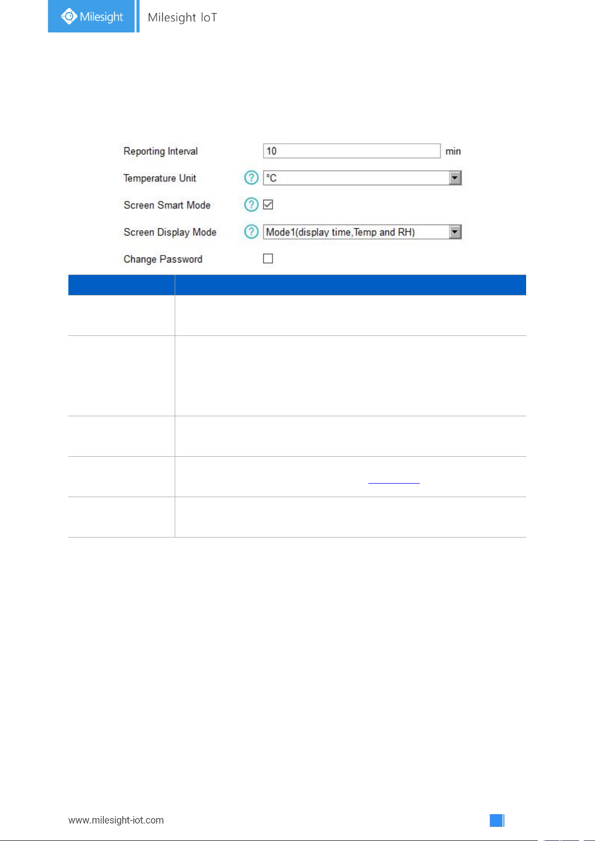
Parameters
Description
Reporting Interval
Reporting interval of transmitting data to network server.Default: 600s
Note: RS232 transmission will not follow the reporting interval.
Temperature Unit
Change the temperature unit displayed on the ToolBox and screen.
Note:
1) The temperature unit in the reporting package is fixed as °C.
2) Please modify the threshold settings if the unit is changed.
Screen Smart Mode
When PIR value is 0 and last for 20 mins, the screen will stop updating to
save battery life.
Screen Display
Mode
Change the screen display contents(see section 2.3).
Change Password
Change the password for ToolBox App or software to read/write this
device.
Go to “Device Settings->Basic” of ToolBox software or “Device->Setting->General Settings” of
ToolBox App to change the reporting interval, screen mode, etc.
4.5 Advanced Settings
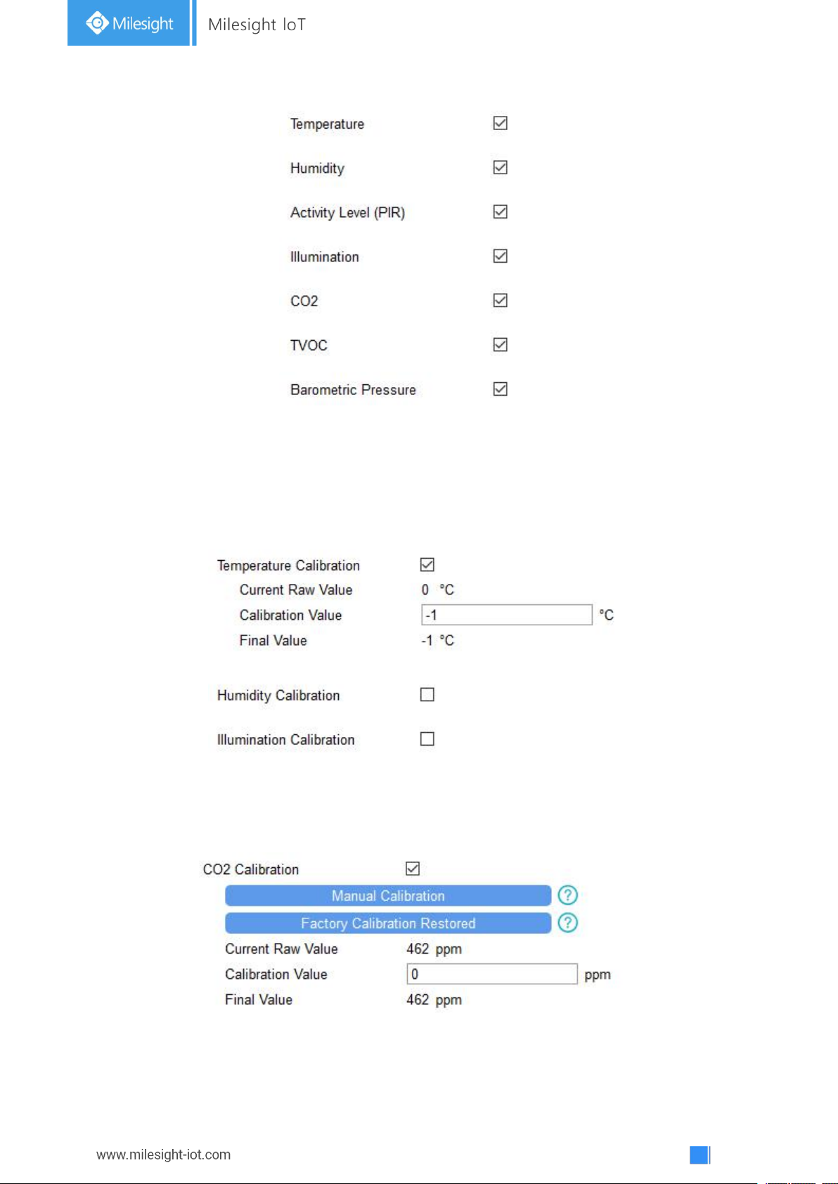
4.5.1 Data Collection Settings
Go to “Device Settings->Basic” of ToolBox software or “Device->Setting->Data Collection
Settings” of ToolBox App to select the data you need to monitor. If any item disabled, the screen
will stop updating it and there will not data on the reporting package.
Page 17
17
4.5.2 Calibration Settings
ToolBox supports numerical calibration for all items. Go to “Device Settings->Basic” of ToolBox
software or “Device->Setting->Calibration Settings” of ToolBox App to type the calibration value
and save, the device will add the calibration value to raw value.
Besides numerical calibration, ToolBox provides more calibration methods for CO2:
Manual Calibration: Put the device in an open outdoor environment more than 10 minutes and
click this button to calibrate the CO2value.
Factory Calibration Restored: Clean the manual calibration and turn back to factory calibration.
Page 18
18
4.5.3 Threshold Settings
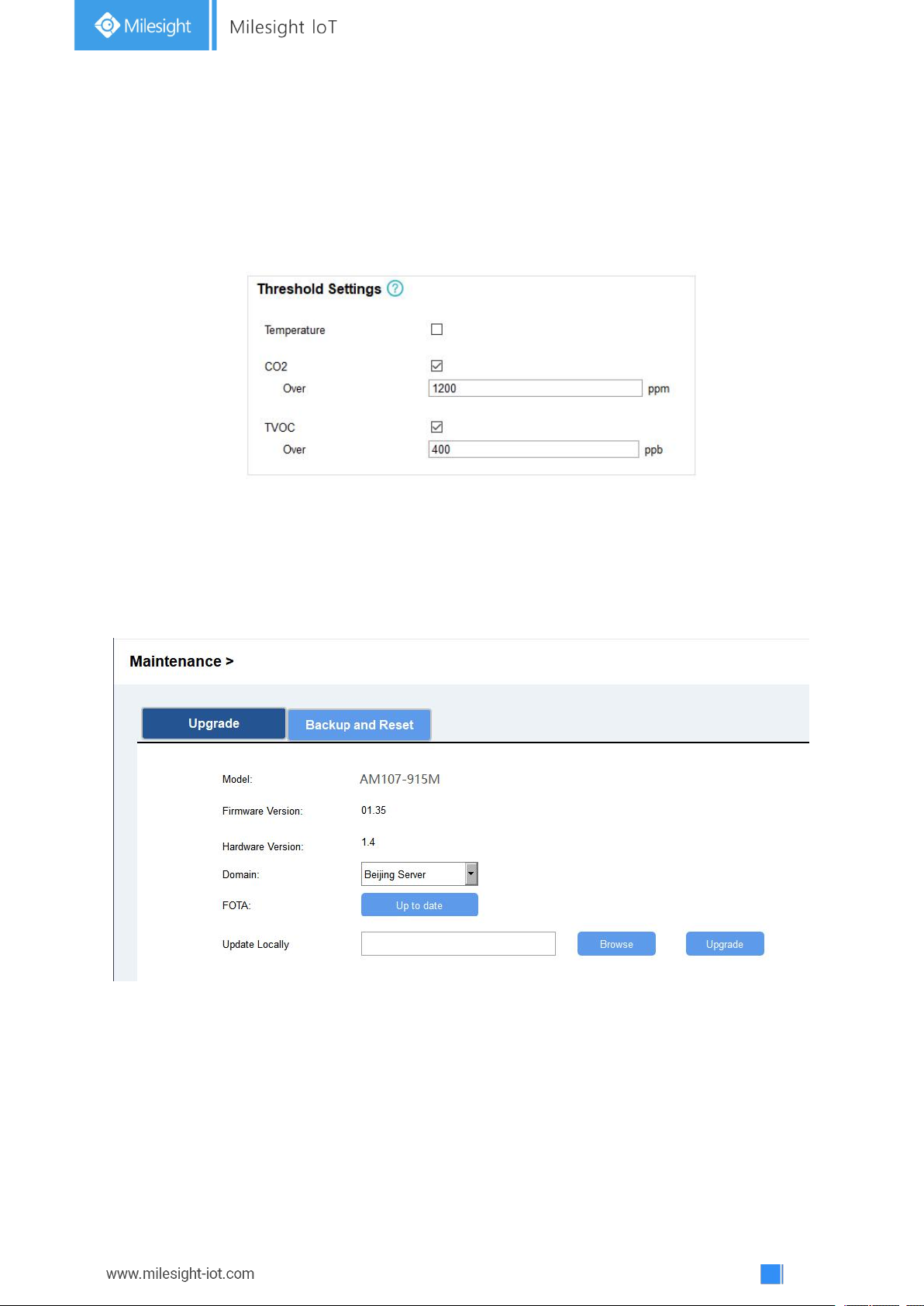
AM100 series will upload the current data instantly after the threshold is triggered. AM107 will
also show alarms of CO2and TVOC on the screen.
Go to “Device Settings->Basic” of ToolBox software or “Device->Setting->Threshold Settings”
of ToolBox App to enable the threshold settings and input the threshold.
4.6 Maintenance
4.6.1 Upgrade
AM100 series support upgrade locally or over the air only via ToolBox software.
Upgrade Locally:
Step 1: Click “Browse” to import firmware from your computer.
Step 2: Click “Upgrade” to start the upgrade.
Upgrade Over the Air:
Step 1: Select the upgraded server according to your region and make sure your computer can
access the Internet.
Page 19
19
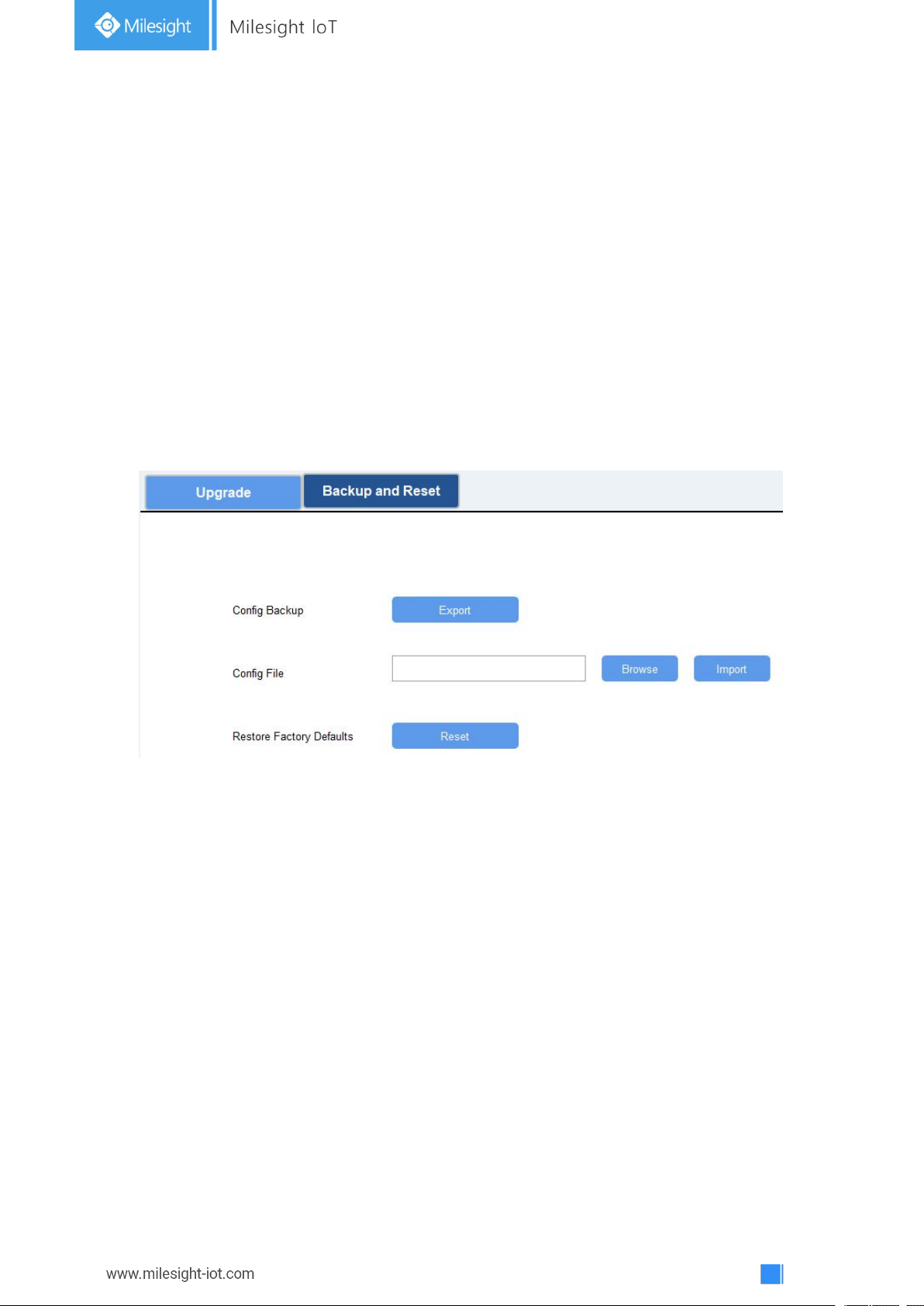
Step 2: Click “Up to date” to search for latest firmware of devices. If your firmware is latest
version, ToolBox will prompt “Your device is up to date”.
Note: Any operation on ToolBox is not allowed during upgrade.
4.6.2 Backup
AM100 devices support configuration backup for easy and quick device configuration in bulk.
Backup is allowed only for devices with the same model and LoRa frequency band. Please select
one of following methods to backup device:
Via ToolBox Software
Step 1: Go to “Maintenance->Backup and Reset”, click “Export” to save current configuration as
json format backup file.
Step 2: Click “Browse” to select backup file, then click “Import” to import the configurations.
Via ToolBox App
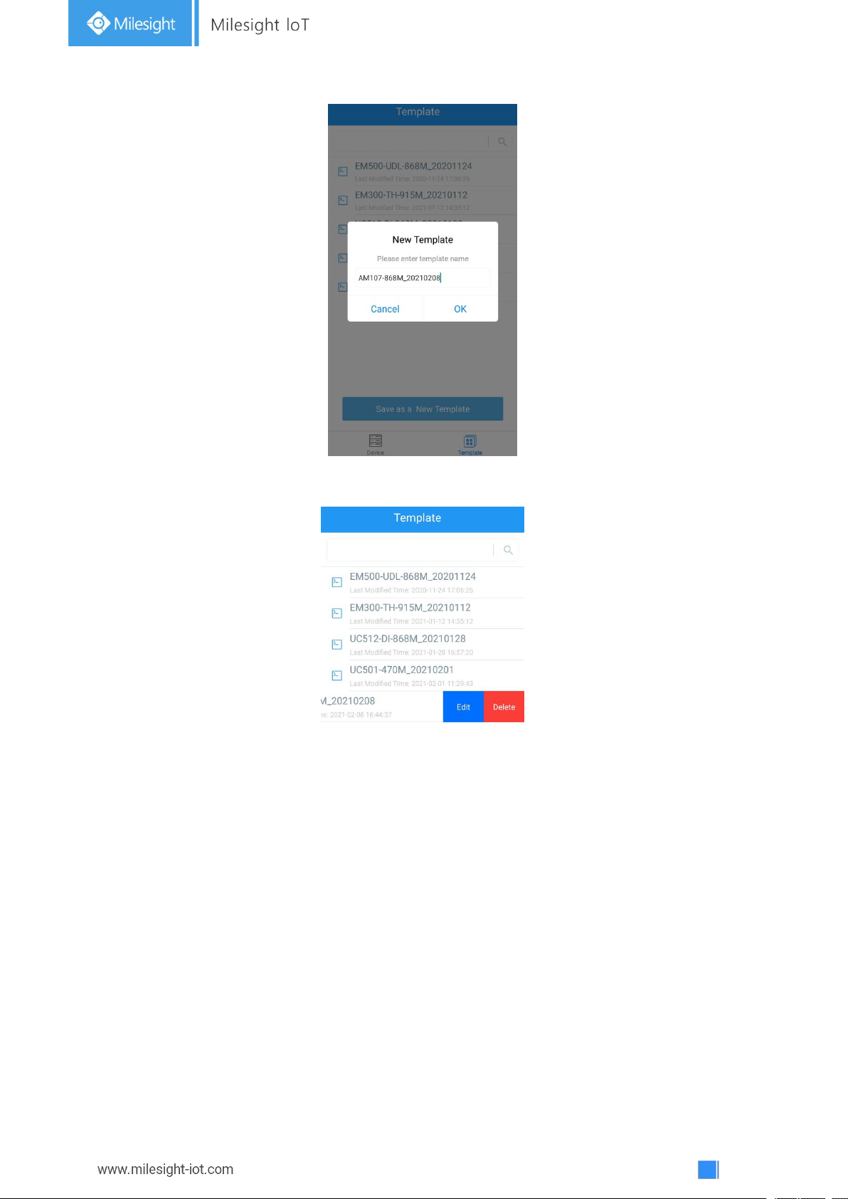
Step 1: Go to “Template” page on the App and save current settings as a template. You can also
edit the template file.
Step 2: Select one template file which saved in the smartphone and click “Write”, then attach to
another device to write configuration.
Page 20
20
Note: Slide the template item left to edit or delete the template. Click the template to edit the
configurations.
4.6.3 Reset to Factory Default
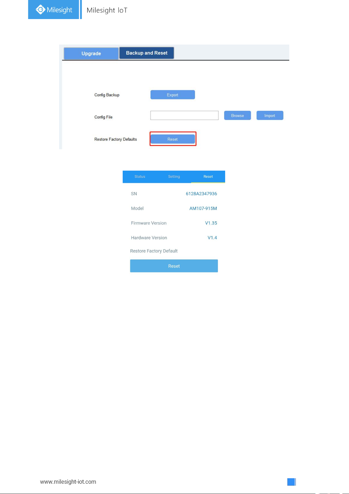
Please select one of following methods to reset device:
Via Hardware: Hold on power button more than 10s.
Via ToolBox Software: Go to “Maintenance->Backup and Reset” to click “Reset”.
Page 21
21
Via ToolBox App: Go to “Device->Reset” to click “Reset”, then attach smart phone with NFC area
to device to complete reset.
5. Installation
5.1 Installation Note
In order to ensure the best detection and LoRaWAN®communication effect, it is recommended
to install AM100 series as follows:
There should not be any isolates or barriers in PIR and light detection range.
Do not mount the device where the temperature is below/above operating range and
temperature varies greatly.
Stay far away from any heat source or cold source like oven, refrigerator.
Do not mount the device close to where airflow varies greatly like windows, vent, fan and air
conditioner.
Do not mount the device upside down.
Do not place the device right to the window or door. If you have to, you’d better pull the
curtain.
It is recommended to install at least 1.5m high from floor.
Page 22
22
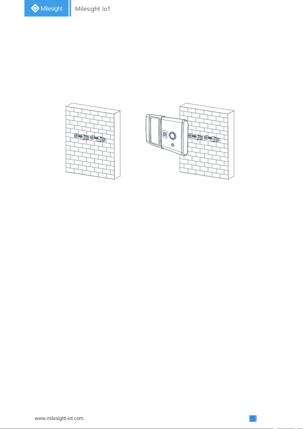
5.2 Wall Mounting
1. Attach the mounting sticker to the wall.
2. Drill two mounting holes are according to the sticker’s mark (around 88mm).
Note: The connecting line of two holes must be a horizontal line.
3. Drive the wall plugs and wall mounting screws into wall at the marks using screw driver.
4. Mount the device on the wall.
6. Milesight IoT Cloud Management
AM100 series can be managed by Milesight IoT Cloud platform. Milesight IoT cloud is a
comprehensive platform that provides multiple services including device remote management
and data visualization with the easiest operation procedures. Please register a Milesight IoT
Cloud account before operating following steps.
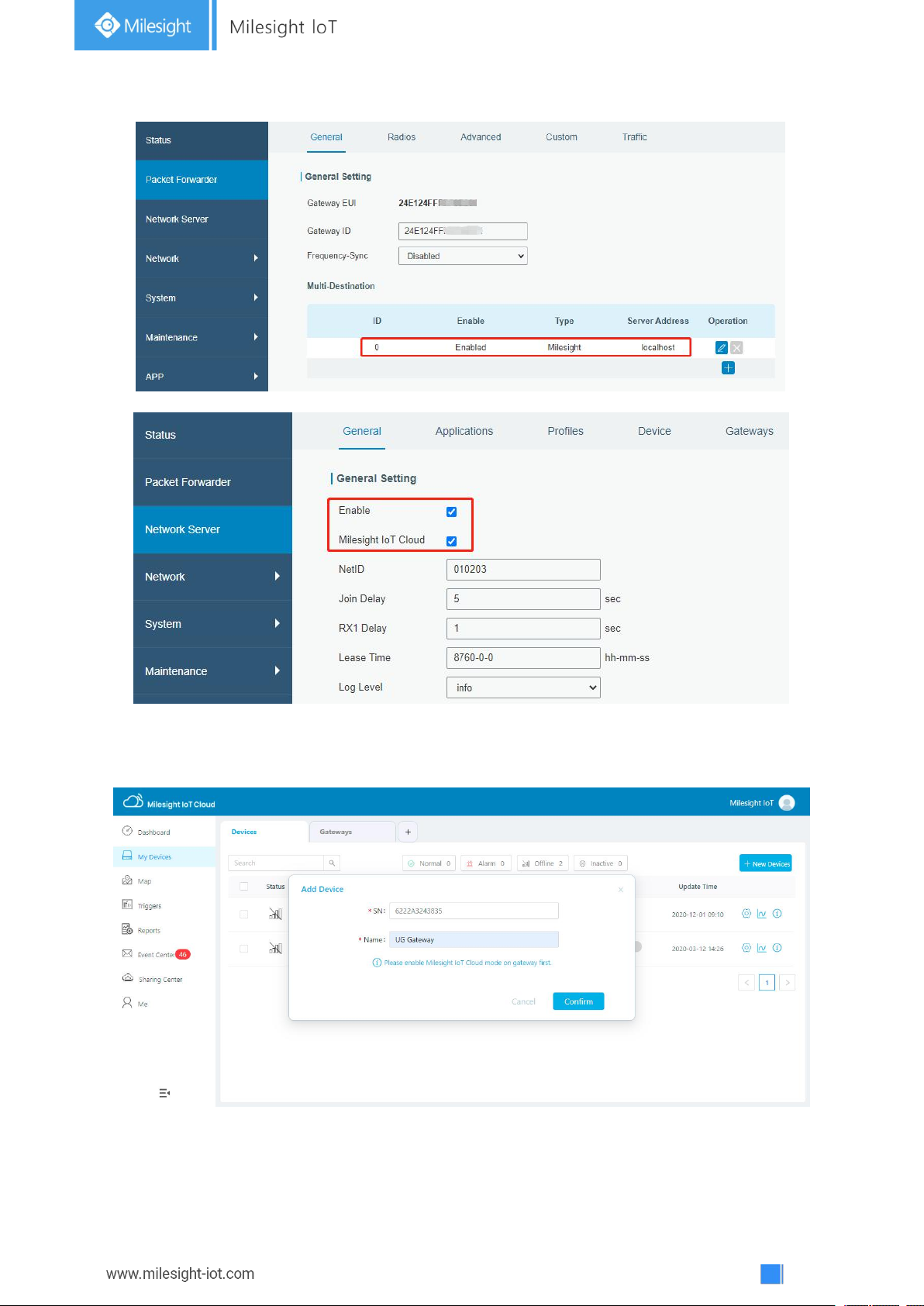
6.1 Add a Milesight Gateway
Step 1: Enable “Milesight” type network server and “Milesight IoT Cloud” mode in gateway web
GUI.
Note: Ensure gateway has accessed the Internet.
Page 23
23
Step 2: Go to “My Devices” page and click “+New Devices” to add gateway to Milesight IoT Cloud
via SN. Gateway will be added under “Gateways” menu.
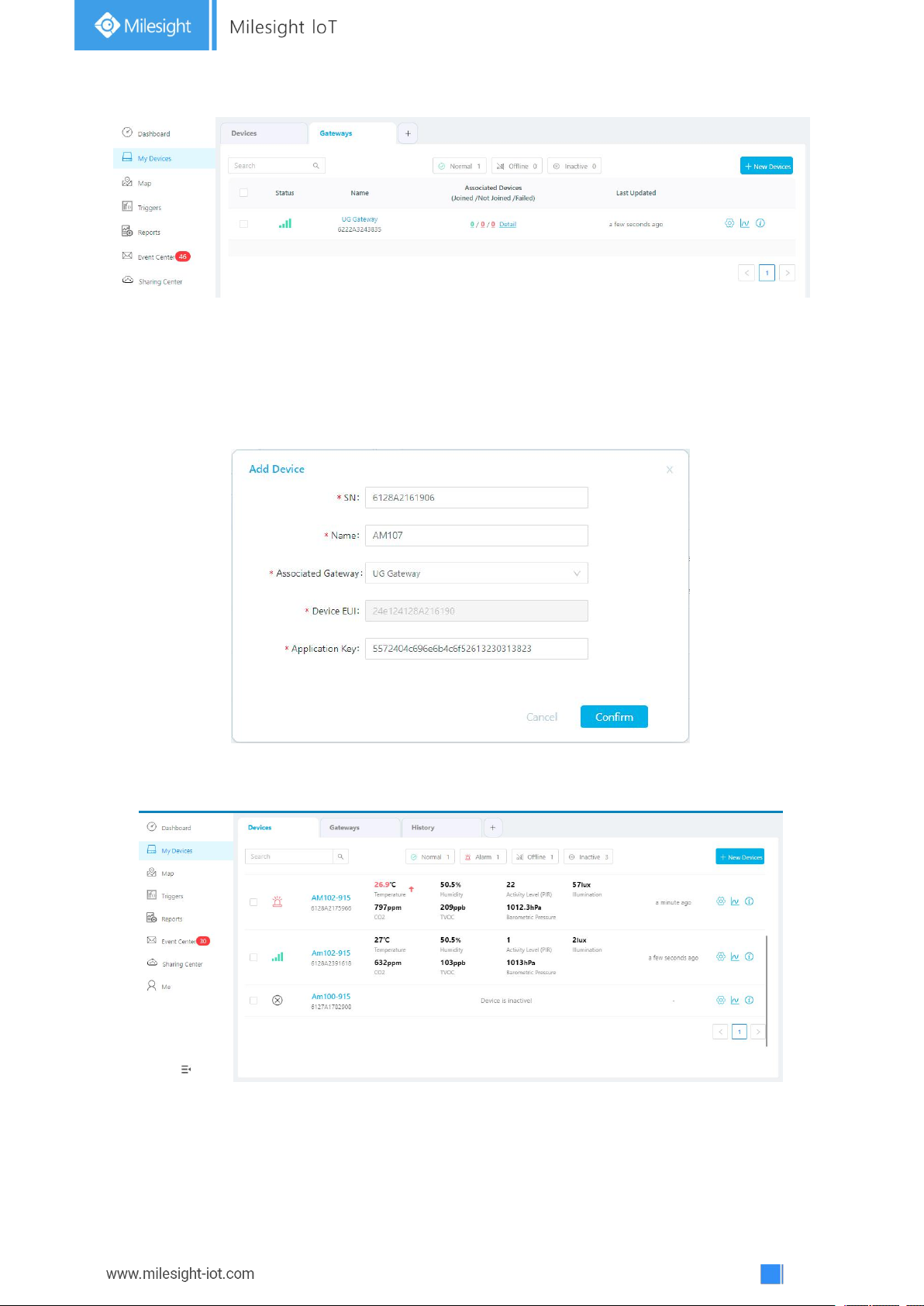
Step 3: Check if gateway is online in Milesight IoT Cloud.
Page 24
24
6.2 Add AM104/AM107 to Milesight IoT Cloud
Step 1: Go to “My Devices” page and click “+New Devices”. Fill in the SN of device and select
associated gateway.
Step 2: After the device is online in Milesight IoT Cloud, you can check the data via webpage or
mobile App and create dashboard for it.
Page 25
25
7. Device Payload
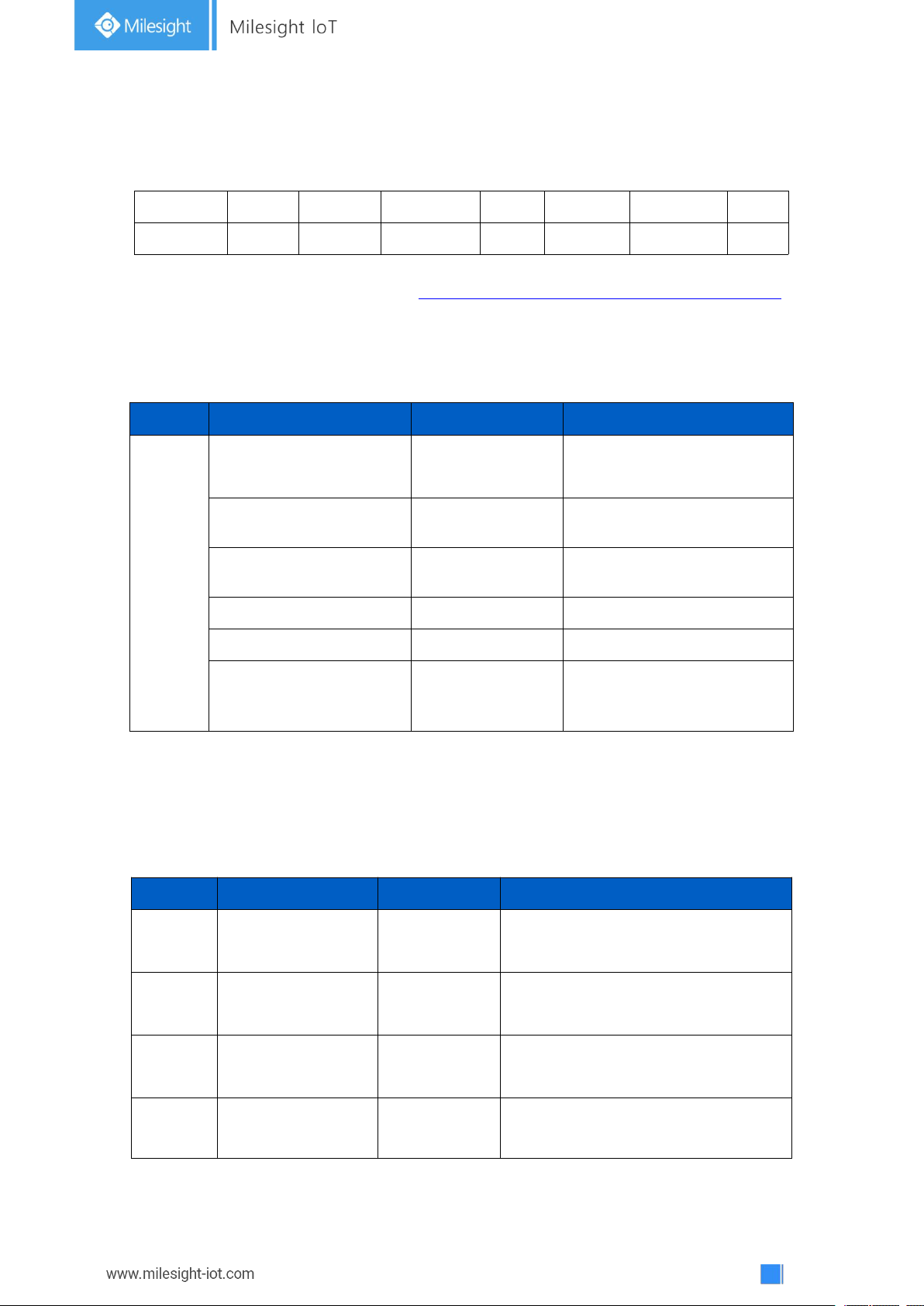
Channel1
Type1
Data1
Channel2
Type2
Data2
Channel 3
...
1 Byte
1 Byte
N Bytes
1 Byte
1 Byte
M Bytes
1 Byte
...
Channel
Type
Data Example
Description
ff
01(Milesight Protocol
Version)
01
V1
08(Device SN)
61 27 a2 17 41 32
Device SN is
6127a2174132
09 (Hardware Version)
01 40
V1.4
0a(Software Version)
01 14
V1.14
0f(Device Type)
00
Class A
18 (Sensor Status)
00 7f
00=>all sensors
7f=>0111 1111
means all sensors are open
Channel
Type
Data Example
Description
01
75(Battery Level)
64
64=>100
Battery level =100%
03
67 (Temperature)
10 01
10 01 => 01 10 = 272
Temp=272*0.1=27.2°C
04
68(Humidity)
71
71=>113
Hum=113*0.5=56.5%
05
6a(Activity Level)
49 00
49 00 => 00 49 =73
Activity Level = 73
All data are based on following format(HEX):
For decoder examples please find files on https://github.com/Milesight-IoT/SensorDecoders.
7.1 Basic Information
AM100 series sensors report basic information of sensor everytime joining the network.
7.2 Sensor Data
AM100 series sensors report sensor data according to reporting interval (10min by default).
Battery level is reported every 24 hours.
Page 26
26
7.3 Downlink Commands
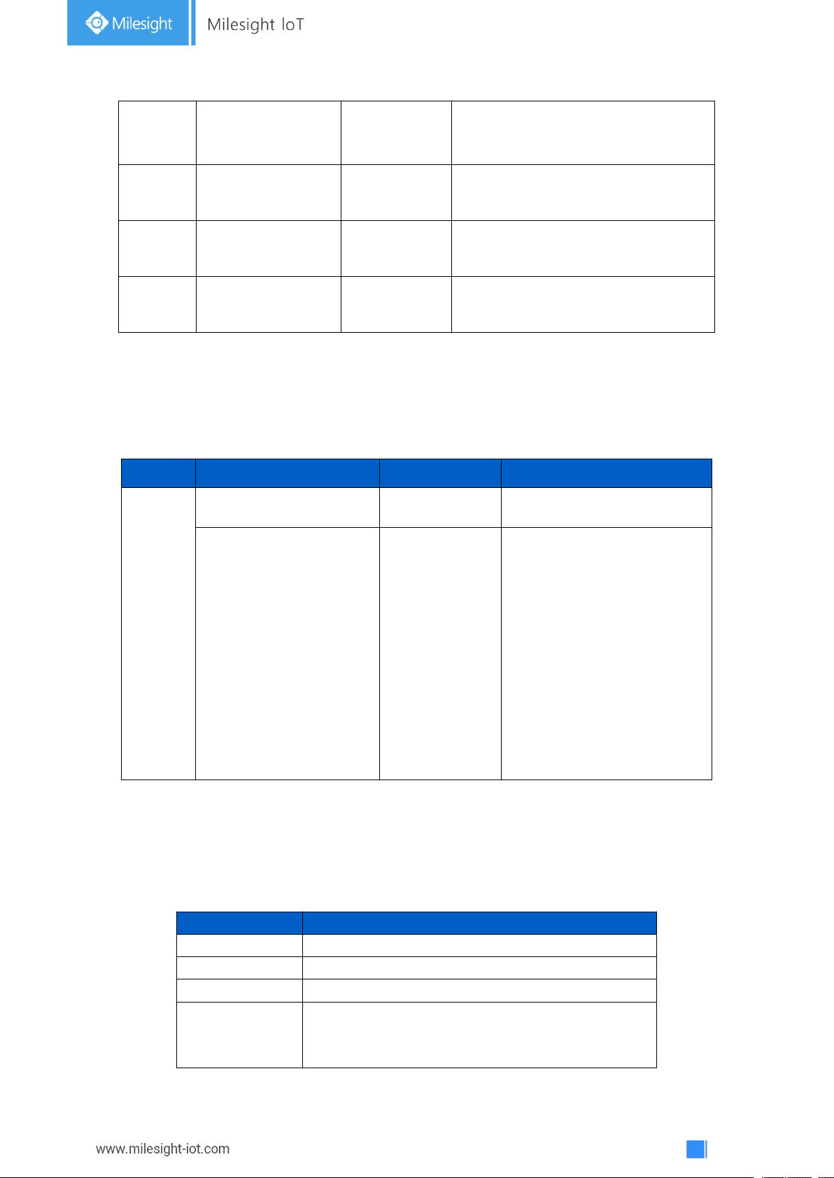
CO2Level
Description
400ppm
Normal outdoor air level.
400-1000ppm
Typical level indoors with good ventilation.
1000-2000ppm
Poor air quality - requires ventilation.
≥2000ppm
Headaches, sleepiness and stagnant, stale, stuffy
air. Poor concentration, loss of attention, increased
heart rate and slight nausea may also be present.
06
65(Illumination)
1c 00 79 00
14 00
Illumination: 1c 00 => 00 1c =28 lux
Visible + Infrared: 79 00=> 00 79= 121
Infrared: 14 00=> 00 14= 20
07
7d(CO2)
67 04
67 04 => 04 67 =1127
CO2= 1127 ppm
08
7d(TVOC)
07 00
07 00 => 00 07=7
TVOC = 7 ppb
09
73(Barometric
Pressure
)
68 27
68 27=>27 68=10088
Pressure=10088*0.1=1008.8hPa
Channel
Type
Data Example
Description
ff
03(Set Reporting Interval)
b0 04
b0 04 => 04 b0 = 1200s
18 (Enable/disable
sensor)
01 01
(Enable
Temperature)
Byte 1: Select Sensor
01: Temperature
02: Humidity
03: PIR
04: Light
05: CO
2
06: TVOC
07: Barometric Pressure
Byte 2: 00=disable, 01=enable
AM100 series sensors support downlink commands to configure the device. Application port is
85 by default.
Appendix
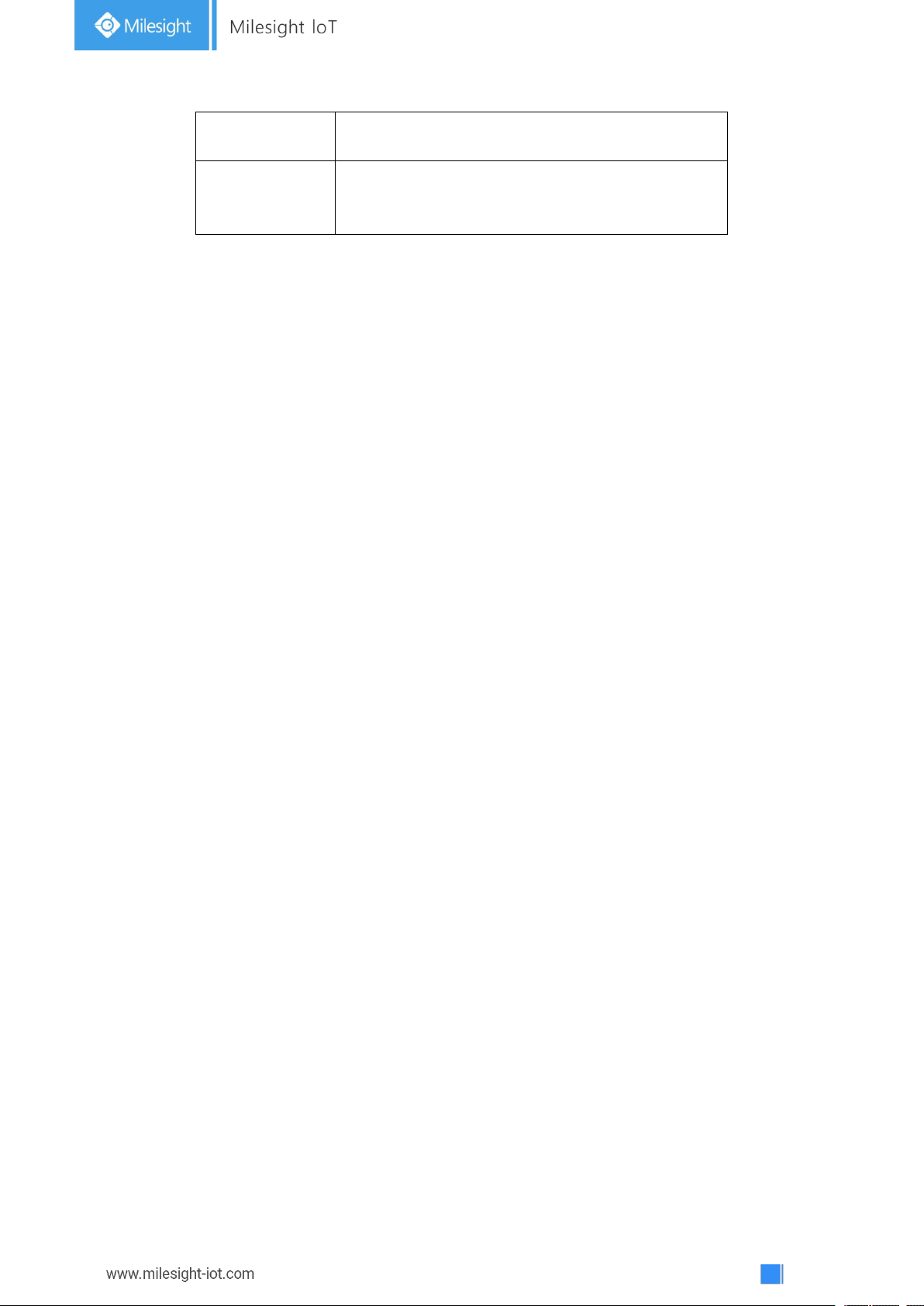
Carbon Dioxide Levels and Guidelines
Page 27
27
5000ppm
Workplace exposure limit (as 8-hour TWA) in most
jurisdictions.
>40000ppm
Exposure may lead to serious oxygen deprivation
resulting in permanent brain damage, coma, even
death.
-END-
 Loading...