

Page 1

Produktgruppe 512, 522 Umbau- und Montageanweisung
1 von 36 M.-Nr. 07707490
27.10.2009 Diese Unterlagen dürfen ohne unsere Genehmigung weder vervielfältigt noch Dritten zugänglich gemacht werden. Eigentumsrechte vorbehalten.
PW 6080, PT 7186
x
de
ni
sv
el
Montageanweisung
Unterbausockel UO 6008 /
UG 6008
Montage-instructie sokkel
UO 6008 / UG 6008
Monteringsanvisning sockel
UO 6008/UG 6008
Οδηγία τοποθέτησης για
σοβατεπί κάτω από πάγκο
UO 6008 / UG 6008
en
da
it
am
Fitting instructions Plinth UO 6008 / UG 6008
Monteringsanvisning
underbygningssokkel
UO 6008 / UG 6008
Istruzione di modifica base
UO 6008 / UG 6008
Stand UO 6008 / UG 6008
Installation
fr
no
es
Notice de montage socle
UO 6008 / UG 6008
Monteringsveiledning for
innbyggingssokkel UO 6008 /
UG 6008
Instrucciones de montaje del
zócalo UO (base abierta) /
UG (base cerrada)
Page 2
1
2
3
4
Produktgruppe 512, 522 Umbau- und Montageanweisung
2 von 36 M.-Nr. 07707490
27.10.2009 Diese Unterlagen dürfen ohne unsere Genehmigung weder vervielfältigt noch Dritten zugänglich gemacht werden. Eigentumsrechte vorbehalten.
x
Page 3
5
6
7
Produktgruppe 512, 522 Umbau- und Montageanweisung
3 von 36 M.-Nr. 07707490
27.10.2009 Diese Unterlagen dürfen ohne unsere Genehmigung weder vervielfältigt noch Dritten zugänglich gemacht werden. Eigentumsrechte vorbehalten.
x
Page 4

Produktgruppe 512, 522 Umbau- und Montageanweisung
4 von 36 M.-Nr. 07707490
27.10.2009 Diese Unterlagen dürfen ohne unsere Genehmigung weder vervielfältigt noch Dritten zugänglich gemacht werden. Eigentumsrechte vorbehalten.
de
Benötigte Teile
x
Anzahl M.-Nr. Benennung
1 07689330 Montagesatz Sockel UO 6008
1 07129240 Montagesatz Sockel UG 6008
Hinweis
Diese Umbauarbeiten dürfen grundsätzlich nur von einer Elektrofachkraft (fachliche Ausbildung, Fachkenntnisse und Facherfahrungen,
zeitnahe berufliche Tätigkeit) unter Berücksichtigung der gültigen Sicherheitsbestimmungen durchgeführt werden.
Für die Instandsetzung, Änderung, Prüfung und Wartung elektrischer Geräte sind die entsprechenden gesetzlichen Grundlagen,
Unfallverhütungsvorschriften, die gültigen Normen, die der Sicherheit dienen, sowie die am Aufstellungsort gültigen Vorschriften der
Energieversorgungsunternehmen zu beachten.
Hinweis
Wartungsarbeiten an Gasgeräten dürfen, außer durch das Gasversorgungsunternehmen und Vertragsinstallationsunternehmen, nur von
Wartungsunternehmen ausgeführt werden, die den Festlegungen des DVGW-Arbeitsblattes G 676 entsprechen. Wartungsarbeiten an
Gasgeräten dürfen grundsätzlich nur von einer Fachkraft unter Berücksichtigung der gültigen Sicherheitsbestimmungen durchgeführt
werden.
Bevor Wartungsarbeiten am Gerät ausgeführt werden, ist eine Trennung vom Gasnetz unbedingt erforderlich.
Gefahr!
Auch bei ausgeschaltetem Gerät kann Netzspannung an Bauteilen anliegen!
Deshalb ist, bevor Wartungs-, Instandsetzungs- und Umbauarbeiten am Gerät durchgeführt werden, eine sichere Netztrennung von allen
aktiven, spannungsführenden Leitungen sowie anschließend eine Messung der Spannungsfreiheit erforderlich! Es ist eine Trennung vom
Gasnetz erforderlich.
Grundsätzlich muss eine allgemeine Sichtprüfung durchgeführt werden.
Ein nicht fachgerechter Umbau kann zum Brand oder zur Gas-Explosion führen.
Gefahr!
Verletzungsgefahr bei der Montage
• Stromschlaggefahr. Vor Wartungs- und Instandsetzungsarbeiten an der Maschine, alle spannungsführenden Leitungen vom Netz
trennen.
• Den Sockel nur an Waschautomaten montieren, die nicht installiert sind. Deinstallation siehe Maschinen-Gebrauchsanweisung.
• Quetschgefahr. Rutschfeste Handschuhe und Sicherheitsschuhe tragen.
• Quetschgefahr. Darauf achten, dass keine Körperteile, insbesondere Hände und Füße, unter oder zwischen die Maschinen
gelangen.
• Unfallgefahr. Sicherstellen, dass während der Montagearbeiten keine Personen oder Tiere in den Arbeitsbereich gelangen
können.
• Verletzungsgefahr, insbesondere Verletzung der Wirbelsäule. Das Gewicht der Maschine im Verhältnis zur eigenen körperlichen
Kraft beachten. Gewichtsangabe der Maschine siehe Maschinen-Gebrauchsanweisung.
Kippgefahr. Verletzungsgefahr durch fehlerhafte Montage
• Die Maschinen stets mit dem Sockel verschrauben.
• Bei Einzelaufstellung den Sockel mit dem Zubehör Fundamentbefestigung M.-Nr. 01497252 auf dem Fußboden befestigen. Im
Umbausatz enthalten.
• Bei der Bodenbefestigung vier Sockelfüße am Boden befestigen.
• Den Sockel nicht für eine Waschtrockensäule verwenden.
Page 5
Produktgruppe 512, 522 Umbau- und Montageanweisung
5 von 36 M.-Nr. 07707490
27.10.2009 Diese Unterlagen dürfen ohne unsere Genehmigung weder vervielfältigt noch Dritten zugänglich gemacht werden. Eigentumsrechte vorbehalten.
Hinweis
Erforderliches Werkzeug:
• Wasserwaage zum lotrechten und waagerechten Ausrichten des Sockels
• Maulschlüssel Schlüsselweite 10 mm für Mutter M6
• Schraubendreher Torx 20
Hinweis
Der Montagesatz Sockel UO 6008 M.-Nr. 07689330 oder der Montagesatz Sockel UG 6008 M.-Nr. 07129240 bestehen aus:
• 1 Sockel UO 6008 beim Montagesatz Sockel UO 6008 M.-Nr. 07689330
• 1 Sockel UG 6008,1 x Vorderwand, 2 x Seitenwand,12 x Linsenschraube M4 x 12,4 beim Montagesatz Sockel UG 6008
M.-Nr. 07129240
• 1 Zubehör Fundamentbefestigung mit Schachtel: 4 x Spannlasche / 8 x Scheibe verzinkt B6,4 / 4 x Sechskantschraube
M6 x 20 / 4 x Sechskantmutter M6 / 4 x Dübel S12 / 4 x Scheibe 8,4 / 4 x Sechskant-Holzschraube 8 x 65 / 20 x Unterlegblech /
8 x Scheibe 38 mm Ø
• 1 Zubehör Begleitschriften mit dieser Montageanweisung und Inbetriebnahmekarte. Diese Umbau- und Montageanweisung heißt
“Montageanweisung Unterbausockel UO 6008 / UG 6008”.
Liste der Abbildungen:
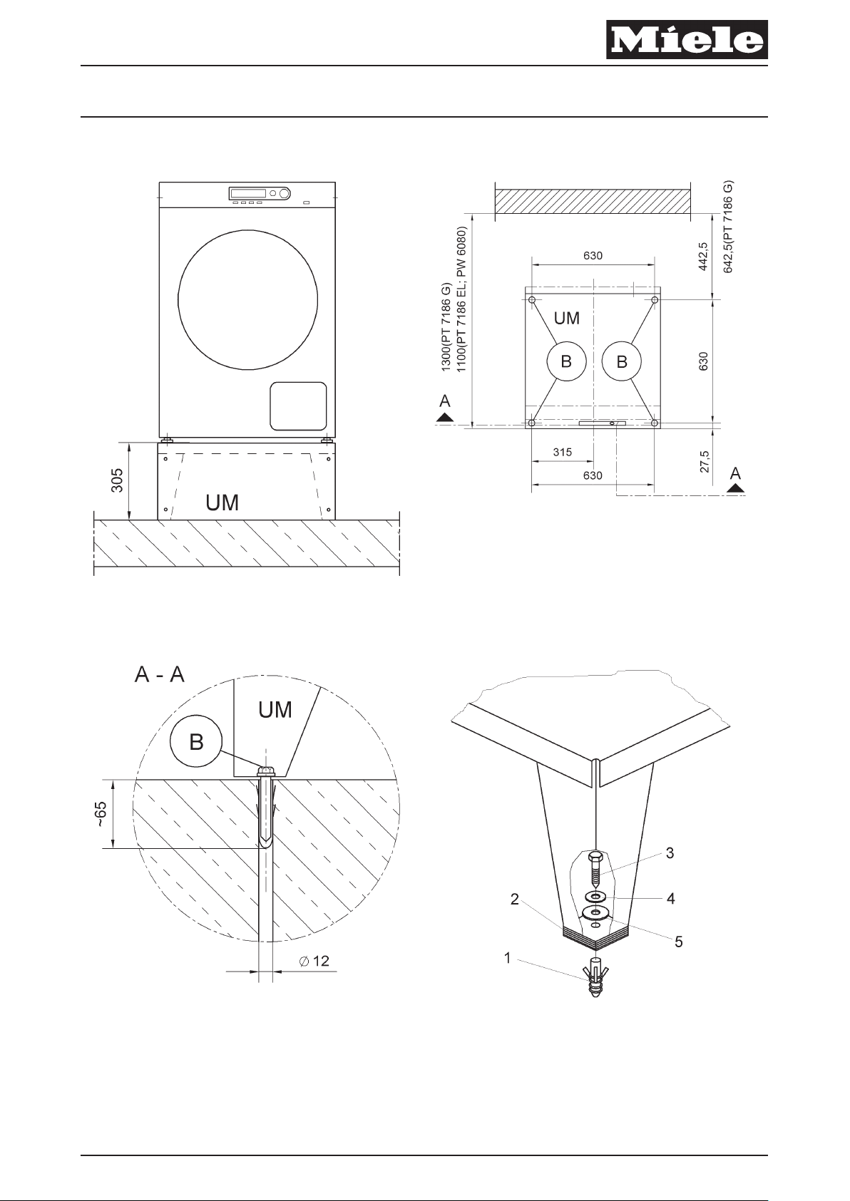
– Abb. 1, Ansicht Sockelhöhe
– Abb. 2, Abstandmaße Bohrungen Bodenbefestigung
– Abb. 3, Bohrungsmaße Bodenbefestigung
– Abb. 4, Montage Bodenbefestigung
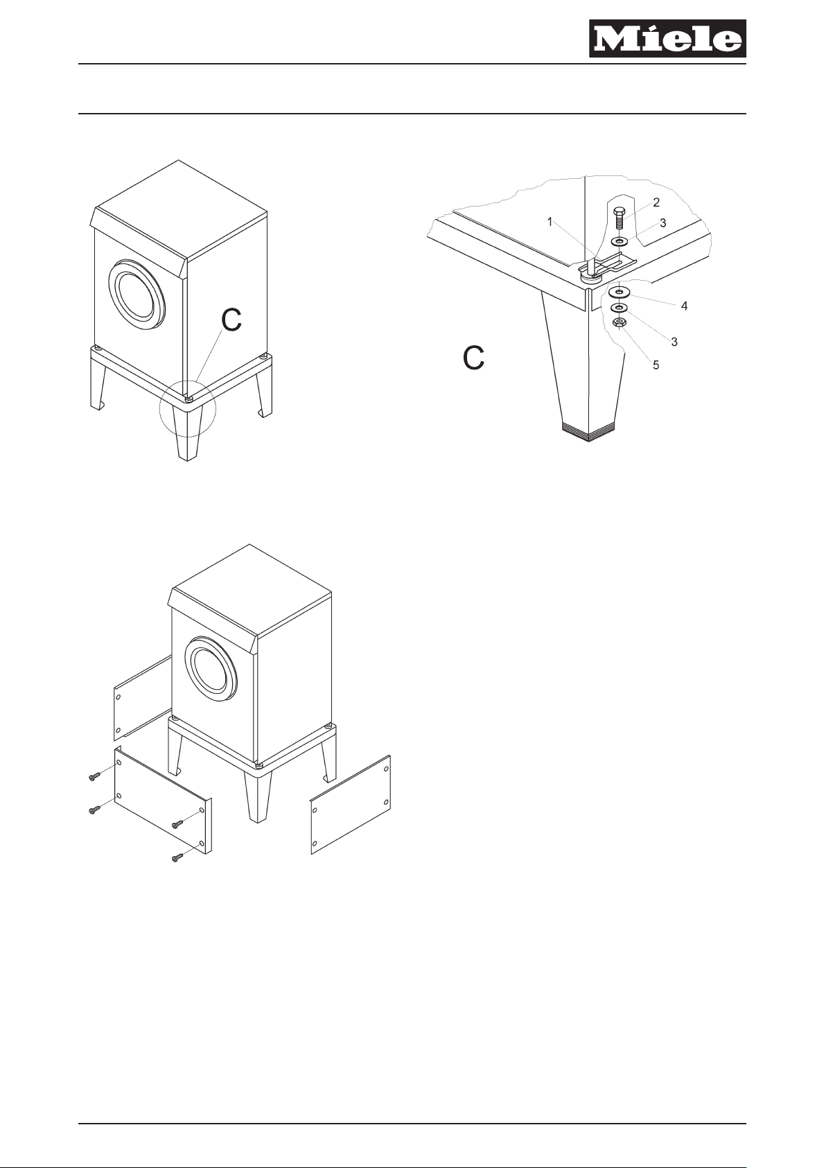
– Abb. 5, Sockel UO 6008
– Abb. 6, Montage Spannlasche
– Abb. 7, Sockel UG 6008
x
Kürzel Erklärung
UM Unterbau Miele, Sockel
A-A Schnittebene
B Bodenbefestigung
C Detaildarstellung
Tabelle 1: Legende Abkürzungen
– Gegebenenfalls den Gasanschluss schließen.
– Die Maschine vom Elektronetz und gegebenenfalls vom Gasnetz trennen und gegen Wiedereinschalten sichern.
– Bohrmaße nach Zeichnung anzeichnen, siehe Abb. 2.
x
Hinweis
Seitlicher Wandabstand der Maschine mindestens 10 mm.
– 4 Bohrungen mit 12 mm Ø ca. 65 mm tief in den Fußboden einbringen, siehe Abb. 3.
– 4 Dübel S12 bündig in die Bohrungen schieben, siehe Abb. 4, Pos. 1.
– Mit Unterlegblechen (Abb. 4, Pos. 2) und Wasserwaage den Sockel lotrecht und waagerecht ausrichten.
– Sockel mit 4 Sechskant-Holzschrauben 8 x 65 (Abb. 4, Pos. 3), Scheiben 8,4 (Abb. 4, Pos. 4) und Scheiben 38 mm Ø
(Abb. 4, Pos. 5) auf dem Fußboden festschrauben.
– Maschine auf den Sockel stellen.
Page 6
Produktgruppe 512, 522 Umbau- und Montageanweisung
6 von 36 M.-Nr. 07707490
27.10.2009 Diese Unterlagen dürfen ohne unsere Genehmigung weder vervielfältigt noch Dritten zugänglich gemacht werden. Eigentumsrechte vorbehalten.
x
Gefahr!
Verletzungsgefahr, insbesondere Verletzung der Wirbelsäule. Das Gewicht der Maschine im Verhältnis zur eigenen körperlichen Kraft
beachten. Gewichtsangabe der Maschine siehe Maschinen-Gebrauchsanweisung.
Quetschgefahr. Darauf achten, dass keine Körperteile, insbesondere Hände und Füße, unter oder zwischen die Maschine gelangen.
– 4 Spannlaschen (Abb. 6, Pos.1) über die Maschinenfüße schieben.
– 4 Sechskantschrauben M6 (Abb. 6, Pos. 2) mit Scheiben verzinkt B6,4 (Abb. 6, Pos. 3) von oben durch die vorhandenen Bohrungen
stecken.
– 4 Spannlaschen von unten mit Scheiben 38 mm Ø Abb. 6, Pos. 4), Scheiben verzinkt B6,4 Abb. 6, Pos. 3) und Sechskantmuttern
M6 Abb. 6, Pos. 5) von unten festschrauben.
x
Gefahr!
Kippgefahr und Absturzgefahr! Die Sockelbefestigung am Boden und die Maschinenbefestigung am Sockel ist zwingend erforderlich!
Hinweis
Abwasseranschluss in den Boden oder die Wand siehe “Installationsplan PW 6080”
Hinweis
Befestigungsmaterial für schwimmenden Estrich ist bauseits zu erbringen.
Sockel UG 6008
– 2 Seitenwände mit Linsenschrauben M4 x 12,4 (Torx 20) festschrauben, siehe Abb. 7.
– Vorderwand mit Linsenschrauben M4 x 12,4 (Torx 20) festschrauben, siehe Abb. 7.
– Eine Sicherheitsprüfung durchführen.
– Die Maschine mit dem Elektronetz und gegebenenfalls mit dem Gasnetz verbinden.
– Einen Funktionstest entweder mit Serviceprogrammen oder einem Waschprogramm durchführen. Dichtigkeit vom
Wasserablaufstutzen der Maschine bis zum Abwasseranschluss im Boden oder in die Wand prüfen.
de
Page 7

Produktgruppe 512, 522 Umbau- und Montageanweisung
7 von 36 M.-Nr. 07707490
27.10.2009 Diese Unterlagen dürfen ohne unsere Genehmigung weder vervielfältigt noch Dritten zugänglich gemacht werden. Eigentumsrechte vorbehalten.
en
Parts required
x
Quantity Mat. no. Designation
1 07689330 Fitting kit - Plinth UO 6008
1 07129240 Fitting kit - Plinth UG 6008
Note
Service and repair work should only be carried out by a suitably qualified electrician (with specialist training, knowledge and experience,
and recent related work experience) in accordance with all appropriate local and national safety regulations.
Servicing, modification, testing and maintenance of electrical appliances should only be carried out in accordance with all appropriate
legal requirements, accident prevention regulations and valid standards. All regulations of the appropriate utility supply companies and
standards relating to safety (not limited to electrical safety) are to be complied with.
Note
Service and repair work on gas machines should only be carried out by suitably qualified persons in accordance with all appropriate local
and national safety regulations. Ensure all special regulations applying to gas installations are also complied with.
Before any service work is commenced, the machine must be disconnected from the gas mains.
Danger!
Even with the machine switched off, mains voltage may be applied to some components.
Before any service work is commenced, the machine must be disconnected from the mains. Suitable measurements must be made to
ensure that this is the case. The machine must be disconnected from the gas mains.
A general visual check should always be carried out.
Incorrect conversion or service work could lead to a risk of fire or gas explosion
Danger!
Risk of injury during fitting.
• Risk of electric shock. Before any service work is commenced, the machine must be disconnected from the mains.
• Fitting can only be carried out with the washing machine or tumble dryer not installed. For deinstallation, see the appropriate
operating instructions.
• Risk of crushing. When carrying out work, wear slip-proof working gloves and safety shoes.
• Risk of crushing. When carrying out work, ensure that parts of the body, especially the hands and feet are not positioned under or
between machines.
• Risk of accident. Ensure that children or pets cannot access the work area while fitting work is being carried out.
• Risk of injury, particularly to the back. The relation of the weight of the machine to the physical strength of the technician must be
taken into account. For machine weight details, see the appropriate operating instructions.
Risk of toppling over. Risk of injury due to incorrect fitting.
• Always bolt the machine to the plinth.
• With a single machine installation, secure the plinth to the floor with the fastening accessory, Mat. no. 01497252, supplied with the
kit.
• With floor fastening, secure all four plinth feet.
• The plinth must not be used with a washer-dryer stack.
Page 8
Produktgruppe 512, 522 Umbau- und Montageanweisung
8 von 36 M.-Nr. 07707490
27.10.2009 Diese Unterlagen dürfen ohne unsere Genehmigung weder vervielfältigt noch Dritten zugänglich gemacht werden. Eigentumsrechte vorbehalten.
x
Note
Tools required:
• Spirit level for plinth levelling
• Open spanner 10 mm for M6 nut
• Torx screwdriver, T 20
Note
The fitting kit - Plinth UO 6008 Mat. no. 07689330, or fitting kit - Plinth UG 6008, Mat. no. 07129240, contains the following:
• 1 plinth UO 6008, with fitting kit - Plinth UO 6008, Mat. no. 07689330
• 1 plinth UG 6008, 1 x Front panel, 2 x Side panel,12 x Raised-head screw M4 x 12.4, with fitting kit - Plinth UG 6008, Mat. no.
07129240
• 1 floor fastening accessory pack containing the following: 4 x Clamp, 8 x Galvanised washer B6.4, 4 x Bolt M6 x 20, 4 x Nut M6,
4 x Rawl plug S12, 4 x Washer 8.4, 4 x Hexagon head wood screw 8 x 65, 20 x Spacer plate, 8 x Washer 38 mm Ø
• 1 information sheet with these instructions and commissioning card. These fitting instructions are called “Fitting instructions Plinth UO 6008 / UG 6008”.
List of illustrations:
– Fig. 1, plinth height
– Fig. 2, floor fastening drilling plan
– Fig. 3, floor fastening hole dimensions
– Fig. 4, floor fastening
– Fig. 5, plinth UO 6008
– Fig. 6, clamp fitting
– Fig. 7, plinth UG 6008
x
Abbreviation Explanation
UM Miele plinth
A-A Section plane
B Floor fastening
C Detail
Table 1: Abbreviation legend
– Close the gas stopcock if applicable.
– Disconnect the machine from the gas (if applicable) and electric mains and ensure utilities cannot be switched on again in error.
– Mark hole positions in accordance with the drawing, see Fig. 2.
x
Note
The gap between the machine and a wall at the side must be at least 10 mm.
– Drill 4 holes 12 mm Ø approx. 65 mm deep in the floor as shown, see Fig. 3.
– Insert 4 S12 Rawl plugs flush in the holes, see Fig. 4, Pos. 1.
– Fit spacer plates, Fig. 4, Pos. 2, as appropriate and use the spirit level to level the plinth.
– Secure the plinth with four 8 x 65 hexagon head wood screws, Fig. 4, Pos. 3, 8.4 washers, Fig. 4, Pos. 4and 38 mm Ø washers,
Fig. 4, Pos. 5, to the floor.
– Place the machine on the plinth.
x
Danger!
Risk of injury, particularly to the back. The relation of the weight of the machine to the physical strength of the technician must be taken
into account. For machine weight details, see the appropriate operating instructions.
Risk of crushing. When carrying out work, ensure that parts of the body, especially the hands and feet are not positioned under or
between machines.
Page 9

Produktgruppe 512, 522 Umbau- und Montageanweisung
9 von 36 M.-Nr. 07707490
27.10.2009 Diese Unterlagen dürfen ohne unsere Genehmigung weder vervielfältigt noch Dritten zugänglich gemacht werden. Eigentumsrechte vorbehalten.
– Slide 4 clamps, Fig. 6, Pos.1over the machine feet.
– Insert four M6 bolts, Fig. 6, Pos. 2, with B6.4 galvanised washers, Fig. 6, Pos. 3, from above through the existing holes.
– Secure the 4 clamps from below with 38 mm Ø washers, Fig. 6, Pos. 4, B6.4 galvanised washers, Fig. 6, Pos. 3, and M6 nuts Fig. 6,
Pos. 5, tightened from below.
x
Danger!
Risk of toppling and falling! It is absolutely essential to secure the plinth to the floor and the machine to the plinth.
Note
For details of the drain connection in the floor or wall, see the PW 6080 installation plan.
Note
Fixing materials for a floating screed floor are to be provided on site.
Plinth UG 6008
– Fit the 2 side panels with M4 x 12.4 raised-head screws (Torx 20), see Fig. 7.
– Fit the 2 side panels with M4 x 12.4 raised-head screws (Torx 20), see Fig. 7.
– Carry out appropriate safety checks.
– Reconnect the machine to the gas (if applicable) and electric mains.
– Carry out a functional test either with the service programme or a wash programme. Check the drain connection from the machine to
the on-site drain in the floor or wall for leaks.
en
Page 10

Produktgruppe 512, 522 Umbau- und Montageanweisung
10 von 36 M.-Nr. 07707490
27.10.2009 Diese Unterlagen dürfen ohne unsere Genehmigung weder vervielfältigt noch Dritten zugänglich gemacht werden. Eigentumsrechte vorbehalten.
fr
Pièces nécessaires
x
Nombre Mat.-Nr. Désignation
1 07689330 Jeu de montage socle UO 6008
1 07129240 Jeu de montage socle UG 6008
Remarque
Les travaux d'adaptation doivent être effectués exclusivement par un technicien qualifié (c'est à dire ayant suivi une formation
spécifique et disposant de connaissances et d'expériences récentes dans le domaine) respectant les prescriptions de sécurité en
vigueur.
La réglementation en vigueur, les prescriptions de prévention des accidents, les normes applicables de sécurité sur le lieu d'installation
ainsi que les prescriptions de la compagnie d'électricité doivent impérativement être respectées pour la réparation, la modification, le
contrôle et la maintenance des appareils électriques.
Remarque
Outre la compagnie de gaz ou l'installateur agréé, seule une société de maintenance répondant aux critères définis dans la
réglementation sur le gaz peut procéder aux interventions sur les appareils gaz. Les travaux doivent être effectués exclusivement par un
technicien qualifié dans le respect des consignes de sécurité en vigueur.
Avant toute maintenance, débrancher impérativement l'appareil du réseau de gaz.
Danger !
Même si l'appareil est déconnecté, les composants peuvent présenter une tension résiduelle.
C'est pourquoi avant d'effectuer tout entretien, réparation ou modification, il est nécessaire de débrancher tous les câbles actifs et sous
tension et d'effectuer une mesure pour s'assurer de l'absence de tension résiduelle ! Débrancher l'appareil du réseau de gaz.
Un contrôle visuel général doit impérativement être effectué.
Si l'adaptation n'est pas effectuée correctement, elle peut causer un incendie ou une explosion de gaz.
Danger !
Risque de blessure lors du montage
• Risque de décharge électrique. Débrancher tous les câbles sous tension avant d'effectuer les travaux d'entretien et de réparation.
• Ne monter le socle que sur les lave-linge non installés. Désinstallation : voir le mode d'emploi de la machine.
• Risque d'écrasement. Utiliser des gants antidérapants et des chaussures de sécurité.
• Risque d'écrasement. Ne pas mettre de parties du corps, en particulier les mains ou les pieds, sous ou entre les machines.
• Risque d'accident. Assurez-vous que les enfants ou les animaux ne peuvent pas pénétrer dans la pièce où les travaux sont
effectués pendant le montage.
• Risque de blessure, en particulier au niveau de la colonne vertébrale. Prenez en compte le poids des appareils et ne surestimez
pas votre force. Indication du poids de la machine, voir mode d'emploi.
Risque de basculement. Risque de blessure en cas de montage incorrect
• Toujours visser les appareils sur le socle.
• En cas d'installation d'une seule machine sur socle, fixer le socle au sol avec le jeu de montage fixation au sol M.-Nr. 01497252.
Fourni avec le jeu de montage.
• Pour la fixation au sol, fixer les quatre pieds au sol.
• Ne pas utiliser le socle pour une colonne lave-linge/sèche-linge
Page 11
Produktgruppe 512, 522 Umbau- und Montageanweisung
11 von 36 M.-Nr. 07707490
27.10.2009 Diese Unterlagen dürfen ohne unsere Genehmigung weder vervielfältigt noch Dritten zugänglich gemacht werden. Eigentumsrechte vorbehalten.
x
Remarque
Outils nécessaires :
• Niveau pour l'installation d'aplomb du socle
• Clé à fourche ouverture de 10 mm pour écrou M6
• Visseuse Torx 20
Remarque
Le jeu de montage socle UO 6008 M.-Nr. 07689330 ou le jeu de montage socle UG 6008 M.-Nr. 07129240 se compose de :
• 1 socle UO 6008 du jeu de montage socle UO 6008 M.-Nr. 07689330
• 1 socle UG 6008, 1 façade, 2 x parois latérales, 12 x vis à tête ronde M4 x 12,4 du jeu de montage socle UG 6008 M.-Nr. 07129240
• 1 accessoire fixation avec boîte : 4 x pattes de fixation / 8 x rondelles galvanisées B6,4 / 4 x vis à six pans creux M6 x 20 /
4 x écrous à six pans M 6 / 4 x chevilles S12 / 4 x rondelles 8,4 / 4 vis à bois à six pans 8 x 65 / 20 x cales / 8 x rondelles 38 mm Ø
• Documents relatifs aux produits avec la présente notice de montage et la carte de mise en service. La présente notice
d'adaptation et de montage "Notice de montage de socle UO 6008 / UG 6008".
Liste des croquis :
– Croquis 1, vue hauteur de socle
– Croquis 2, cotes de distance entre les perçages de fixation au sol
– Croquis 3, cotes des perçages de fixation au sol
– Croquis 4, montage du passage de câble
– Croquis 5, socle UO 6008
– Croquis 6, montage de l'attache de fixation
– Croquis 7, socle UG 6008
x
Abréviation Explication
UM Socle Miele
A-A Niveau de coupe
B Fixation au sol
C Détail
Tableau 1: Légende abréviations
– Fermer le robinet de gaz le cas échéant.
– Débrancher l'appareil du secteur et du réseau de gaz et protéger contre une remise en marche accidentelle.
– Marquer les emplacements de perçage en se conformant à croquis 2.
x
Remarque
Distance matérale avec la machine de 10 mm minimum.
– Effectuer 4 perçages de 12 mm de Ø et de 65 mm de profondeur dans le sol, voir croquis 3
– Insérer 4 chevilles S12 au ras du sol dans les perçages, voir croquis 4, pos.1
– Disposer le socle d'aplomb verticalement et horizontalement (croquis 4, pos. 2) à l'aide des cales et du niveau à bulle.
– Visser le socle avec les vis à bois à six pans 8 x 65 (croquis 4, pos. 3), les rondelles 8,4 (croquis 4, pos. 4) et les rondelles 38 mm Ø
(croquis 4, pos. 5) sur le sol et serrer
– Poser la machine sur le socle.
x
Danger !
Risque de blessure, en particulier au niveau de la colonne vertébrale. Prenez en compte le poids des appareils et ne surestimez pas
votre force. Indication du poids de la machine, voir mode d'emploi.
Risque d'écrasement. Ne pas mettre de parties du corps, en particulier les mains ou les pieds, sous ou entre les machines.
Page 12

Produktgruppe 512, 522 Umbau- und Montageanweisung
12 von 36 M.-Nr. 07707490
27.10.2009 Diese Unterlagen dürfen ohne unsere Genehmigung weder vervielfältigt noch Dritten zugänglich gemacht werden. Eigentumsrechte vorbehalten.
– Poser 4 pattes de fixation (croquis 6, pos. 1) sur les pieds de machine.
– Insérer les 4 vis M6 (croquis 6, pos. 2) avec rondelles galvanisées B6,4 (croquis 6, pos. 3) par le haut dans les perçages.
– Visser les 4 pattes de fixation par le bas avec les rondelles 38 mm Ø (croquis 6, pos. 4), rondelles galvanisées B6,4
(croquis 6, pos. 3) et écrous six pans M6 croquis 6, pos. 5.
x
Danger !
Risque de basculement et de chute ! La fixation de socle au sol et la fixation de la machine au socle sont obligatoires !
Remarque
Raccordement eaux usées dans le sol ou le mur voir "Schéma d'installation PW 6080"
Remarque
Le matériel de fixation pour parquet flottant doit être fourni par l'exploitant.
Socle UG 6008
– Visser les 2 parois latérales avec les vis à tête ronde M4 x 12,4 (Torx 20), voir croquis 7.
– Visser la façade avec les vis à tête ronde M4 x 12,4 (Torx 20), voir croquis 7.
– Effectuer un contrôle de sécurité.
– Raccorder la machine à l'électricité et au gaz le cas échant.
– Effectuer un test fonctionnel soit avec les programmes SAV, soit avec un programme de lavage. Vérifier l'étanchéité du raccord de
vidange de la machine jusqu'au raccordement des eaux usées dans le sol ou le mur.
fr
Page 13

Produktgruppe 512, 522 Umbau- und Montageanweisung
13 von 36 M.-Nr. 07707490
27.10.2009 Diese Unterlagen dürfen ohne unsere Genehmigung weder vervielfältigt noch Dritten zugänglich gemacht werden. Eigentumsrechte vorbehalten.
ni
Benodigde onderdelen
x
aantal Mat.-nr. Benaming
1 07689330 Montageset sokkel UO 6008
1 07129240 Montageset sokkel UG 6008
Opmerking
Deze ombouwwerkzaamheden mogen in principe alleen door een vakman, met inachtneming van alle geldende
veiligheidsvoorschriften worden uitgevoerd.
Voor reparatie, wijziging, controle en onderhoud van elektrische apparaten dient men de desbetreffende wetten,
veiligheidsvoorschriften en de geldende normen in acht te nemen.
Opmerking
Onderhoudswerkzaamheden aan gasapparaten mogen, behalve door het energiebedrijf en gecontracteerde installatiebedrijven, alleen
door erkende onderhoudsbedrijven uitgevoerd worden. Onderhoudswerkzaamheden mogen in principe alleen door een vakman, met
inachtneming van alle geldende veiligheidsvoorschriften worden uitgevoerd.
Voordat er onderhoudswerkzaamheden aan het apparaat uitgevoerd worden, dient het apparaat beslist van het gasnet
losgekoppeld te worden.
Pas op!
Ook als het apparaat uitgeschakeld is, kunnen onderdelen onder spanning staan!
Daarom is het noodzakelijk, voordat er onderhouds-, reparatie- en ombouwwerkzaamheden aan het apparaat uitgevoerd worden, alle
actieve kabels, die onder spanning staan, spanningsvrij te maken en vervolgens te meten of de kabels spanningsvrij zijn! De gastoevoer
moet afgesloten worden.
Er dient een algemene optische controle plaats te vinden.
Een niet deskundig uitgevoerde ombouw kan brand of een explosie veroorzaken.
Pas op!
Gevaar voor verwondingen bij de montage
• Gevaar voor elektrische schok. Voordat u onderhouds- en reparatiewerkzaamheden aan het apparaat uitvoert, dient u alle kabels,
waarop spanning staat, spanningsvrij te maken.
• De sokkel alleen op wasautomaten monteren, die niet geïnstalleerd zijn. Voor de de-installatie zie de gebruiksaanwijzing van het
apparaat.
• Vingers kunnen bekneld raken. Draag stroeve handschoenen en veiligheidsschoenen.
• Vingers kunnen bekneld raken. Let erop, dat er geen lichaamsdelen, in het bijzonder handen en voeten, onder of tussen de
apparaten komen.
• Gevaarlijk. Zorg ervoor, dat tijdens de montagewerkzaamheden geen mensen of dieren in de buurt kunnen komen.
• Gevaar voor verwonding, met name beschadiging van de wervelkolom. Let op het gewicht van de apparaten in verhouding tot de
eigen fysieke kracht. Het gewicht van het apparaat wordt in de gebruiksaanwijzing vermeld.
Het apparaat kan kantelen. Gevaar voor verwonding door verkeerde montage
• De apparaten altijd op de sokkel vastschroeven.
• Als de sokkel alleen opgesteld wordt, maak deze dan aan de vloer vast met de montageset vloerbevestiging mat.-nr. 01497252.
Deze bevindt zich in de ombouwset.
• Zet bij de bevestiging op de bodem de vier voeten van de sokkel op de bodem vast.
• Gebruik de sokkel niet voor een was-droog-zuil.
Page 14

Produktgruppe 512, 522 Umbau- und Montageanweisung
14 von 36 M.-Nr. 07707490
27.10.2009 Diese Unterlagen dürfen ohne unsere Genehmigung weder vervielfältigt noch Dritten zugänglich gemacht werden. Eigentumsrechte vorbehalten.
Opmerking
Benodigd gereedschap:
• Waterpas voor het waterpas afstellen van de sokkel
• Steeksleutel sleutelbreedte 10 mm voor moer M6
• Torx 20 schroevendraaier
Opmerking
De montageset sokkel UO 6008 mat.-nr. 07689330 of de montageset sokkel UG 6008 mat.-nr. 07129240 bestaan uit:
• 1 sokkel UO 6008 bij de montageset sokkel UO 6008 mat.-nr. 07689330
• 1 sokkel UG 6008,1 x voorwand, 2 x zijwand,12 x lenskopschroef M4 x 12,4 bij de montageset sokkel UG 6008 mat.-nr. 07129240
• 1 montageset vloerbevestiging met doos: 4 x spanstrip / 8 x ring verzinkt B6,4 / 4 x zeskantige schroef M6 x 20 / 4 x zeskantige
moer M6 / 4 x duvel S12 / 4 x ring 8,4 / 4 x zeskantige houtschroef 8 x 65 / 20 x opvulplaat / 8 x ring 38 mm Ø
• 1 set documenten bij deze montage-instructie en inbedrijfstellingskaart. Deze ombouw- en montage-instructie heet
"Montage-instructie sokkel UO 6008 / UG 6008".
Overzicht van de afbeeldingen:
– Afb. 1, Aanzicht sokkelhoogte
– Afb. 2, Afstanden boorgaten vloerbevestiging
– Afb. 3, Afmetingen boorgaten vloerbevestiging
– Afb. 4, Montage vloerbevestiging
– Afb. 5, Sokkel UO 6008
– Afb. 6, Montage spanstrip
– Afb. 7, Sokkel UG 6008
x
Afkorting Verklaring
UM Onderbouw Miele, sokkel
A-A Zij-aanzicht
B Bevestiging op de vloer
C Detailweergave
tabel 1: Legenda afkortingen
– Sluit indien nodig de gasaansluiting af.
– Maak het apparaat spanningsvrij en sluit indien nodig de gastoevoer af en beveilig het apparaat tegen inschakeling.
– Afmetingen boorgaten volgens tekening markeren, zie Afb. 2.
x
Opmerking
Afstand van apparaat tot muur aan de zijkant minstens 10 mm.
– Maak 4 boorgaten met 12 mm Ø ca. 65 mm diep in de vloer, zie Afb. 3.
– Schuif 4 duvels S12 naadloos aansluitend in de boorgaten, zie Afb. 4, Pos.1.
– Stel de sokkel waterpas af met opvulplaten en een waterpas (Afb. 4, Pos. 2).
– Schroef de sokkel met de 4 zeskantige houtschroeven 8 x 65 (Afb. 4, Pos. 3), de ringen 8,4 (Afb. 4, Pos. 4) en de ringen 38 mm Ø
(Afb. 4, Pos. 5) op de vloer vast.
– Plaats het apparaat op de sokkel.
x
Pas op!
Gevaar voor verwonding, met name beschadiging van de wervelkolom. Let op het gewicht van de apparaten in verhouding tot de eigen
fysieke kracht. Het gewicht van het apparaat wordt in de gebruiksaanwijzing vermeld.
Vingers kunnen bekneld raken. Let erop, dat er geen lichaamsdelen, in het bijzonder handen en voeten, onder of tussen het apparaat
komen.
Page 15

Produktgruppe 512, 522 Umbau- und Montageanweisung
15 von 36 M.-Nr. 07707490
27.10.2009 Diese Unterlagen dürfen ohne unsere Genehmigung weder vervielfältigt noch Dritten zugänglich gemacht werden. Eigentumsrechte vorbehalten.
– Schuif de 4 spanstrips (Afb. 6, Pos.1) over de voeten van het apparaat.
– Steek de 4 zeskantige schroeven M6 (Afb. 6, Pos. 2) met verzinkte ringen B6,4 (Afb. 6, Pos. 3) van bovenaf door de aanwezige
boorgaten.
– Schroef de 4 spanstrips van onderaf met ringen 38 mm Ø Afb. 6, Pos. 4), verzinkte ringen B6,4 Afb. 6, Pos. 3) en zeskantige moeren
M6 Afb. 6, Pos. 5) vast.
x
Pas op!
Het apparaat kan kantelen en vallen! Het is dringend noodzakelijk, de sokkel op de bodem en het apparaat op de sokkel te bevestigen!
Opmerking
Voor de aansluiting van de waterafvoer op de vloer of de wand zie "Installatieschema PW 6080"
Opmerking
Bevestigingsmateriaal voor speciale vloeren (bijv. met geïsoleerde afdeklaag) wordt niet bijgeleverd.
Sokkel UG 6008
– Schroef de 2 zijwanden met lenskopschroeven M4 x 12,4 (Torx 20) vast, zie Afb. 7.
– Schroef de voorwand met lenskopschroeven M4 x 12,4 (Torx 20) vast, zie Afb. 7.
– Controleer de veiligheid.
– Sluit het apparaat aan op het elektriciteitsnet en indien nodig op het gasnet.
– Controleer met serviceprogramma's of een wasprogramma of het apparaat functioneert. Controleer of de waterafvoertuit van het
apparaat tot aan de aansluiting van de waterafvoer in de vloer of in de wand lekt.
ni
Page 16

Produktgruppe 512, 522 Umbau- und Montageanweisung
16 von 36 M.-Nr. 07707490
27.10.2009 Diese Unterlagen dürfen ohne unsere Genehmigung weder vervielfältigt noch Dritten zugänglich gemacht werden. Eigentumsrechte vorbehalten.
da
Nødvendige dele
x
Antal M.-Nr. Betegnelse
1 07689330 Monteringssæt sokkel UO 6008
1 07129240 Monteringssæt sokkel UG 6008
Bemærk
Denne montering må principielt kun udføres af en fagmand (faglig uddannelse, fagkundskab og -erfaring samt aktuel relevant
beskæftigelse) under hensyntagen til gældende sikkerhedsbestemmelser.
Ved reparation, ændring, kontrol og vedligeholdelse af elektriske produkter skal lovbestemmelserne, de ulykkesforebyggende
forskrifter, de gældende sikkerhedsnormer for de pågældende produkter og energiforsyningsselskabets forskrifter gældende for
opstillingsstedet overholdes.
Bemærk
Ud over gasforsyningsselskaber må kun Miele-teknikere og gas- og vandmestre, som lever op til de lovmæssige krav, foretage reparation
og vedligeholdelse af maskiner med gastilslutning. De gældende sikkerhedsbestemmelser skal til enhver tid overholdes.
Inden der foretages vedligeholdelse eller reparation, skal maskinen være afbrudt fra gasnettet!
Risiko!
Også på slukkede maskiner kan der forekomme netspænding på delene!
Inden der foretages vedligeholdelse, reparation eller ombygning, skal alle spændingsførende ledninger derfor være sikkert afbrudt.
Foretag kontrolmåling! Gastilførslen skal ligeledes afbrydes.
Der skal altid foretages en generel visuel kontrol.
Hvis ombygningen ikke foretages korrekt, er der risiko for brand eller gaseksplosion.
Risiko!
Fare for at komme til skade ved monteringen
• Fare for elektrisk stød. Inden vedligeholdelse og reparation på maskinen påbegyndes, skal alle spændingsførende ledninger
afbrydes fra nettet.
• Monter kun soklen på vaskemaskiner, der ikke er installeret. Afinstallation, se brugsanvisningen til maskinen.
• Fare for at komme i klemme. Bær skridsikre handsker og sikkerhedssko.
• Fare for at komme i klemme. Sørg for, at ingen kropsdele, især ikke hænder eller fødder, kan komme ind under eller ind mellem
maskinerne.
• Fare for uheld. Sørg for, at hverken personer eller dyr har adgang til arbejdsområdet under monteringsarbejdet.
• Fare for at komme til skade, især med rygsøjlen. Vær opmærksom på maskinens vægt i forhold til kropsvægten. Maskinens vægt
fremgår af brugsanvisningen til maskinen.
Fare for at tippe. Fare for at komme til skade på grund af forkert montering
• Skru altid maskinerne fast til soklen.
• Ved opstilling af en enkelt maskine skal soklen fastgøres til gulvet med tilbehøret fundamentfastgørelse M.-Nr. 01497252. Følger
med ombygningssættet.
• Ved fastgørelse til gulvet fastgøres fire sokkelben til gulvet.
• Anvend ikke soklen til en vaske-/tørresøjle.
Page 17

Produktgruppe 512, 522 Umbau- und Montageanweisung
17 von 36 M.-Nr. 07707490
27.10.2009 Diese Unterlagen dürfen ohne unsere Genehmigung weder vervielfältigt noch Dritten zugänglich gemacht werden. Eigentumsrechte vorbehalten.
x
Bemærk
Påkrævet værktøj:
• Vaterpas til lodret og vandret justering af soklen
• Skruenøgle str.10 mm til møtrik M6
• Skruetrækker torx 20
Bemærk
Monteringssæt sokkel UO 6008 M.-Nr. 07689330 eller monteringssæt sokkel UG 6008 M.-Nr. 07129240 består af:
• 1 sokkel UO 6008 i monteringssæt sokkel UO 6008 M.-Nr. 07689330
• 1 sokkel UG 6008,1 x front, 2 x sidevæg,12 x skruer M4 x 12,4 i monteringssæt sokkel UG 6008 M.-Nr. 07129240
• 1 tilbehør fundamentfastgørelse: 4 x spændlasker / 8 x forzinkede skiver B6,4 / 4 x skruer M6 x 20 / 4 x møtrik M6 / 4 x rawlplug
S12 / 4 x skive 8,4 / 4 x sekskant-træskrue 8 x 65 / 20 x underlagsskive / 8 x skive 38 mm Ø
• 1 tilbehør følgeskrivelse med denne monteringsanvisning og ibrugtagningskort. Denne ombygnings- og monteringsanvisning
hedder “Monteringsanvisning underbygningssokkel UO 6008 / UG 6008”.
Liste over illustrationer:
– Ill. 1, oversigt sokkelhøjde
– Ill. 2, afstandsmål huller gulvfastgørelse
– Ill. 3, hulmål gulvfastgørelse
– Ill. 4, montering gulvfastgørelse
– Ill. 5, sokkel UO 6008
– Ill. 6, montering spændlaske
– Ill. 7, sokkel UG 6008
x
Forkortelse Forklaring
UM Underbygning Miele, sokkel
A-A Snitniveau
B Gulvfastgørelse
C Detailbillede
skema 1: Signaturforklaring forkortelser
– Luk i givet fald for gastilførslen.
– Afbryd maskinen fra elnettet og i givet fald fra gasnettet, og sørg for at sikre den mod genindkobling.
– Optegn hulmålene iht. tegningen, se ill. 2.
x
Bemærk
Vægafstand i maskinens side min. 10 mm.
– Lav 4 huller med 12 mm Ø ca. 65 mm dybt i gulvet, se ill. 3.
– Skub 4 rawlplugs S12 ned i hullerne, se ill. 4, Pos. 1.
– Juster soklen lodret og vandret med underlagsskiver (ill. 4, Pos. 2) .
– Skru soklen fast til gulvet med 4 sekskant-træskruer 8 x 65 (ill. 4, Pos. 3), skiver 8,4 (ill. 4, Pos. 4) og skiver 38 mm Ø (ill. 4, Pos. 5).
– Stil maskinen på soklen.
x
Risiko!
Fare for at komme til skade, især med rygsøjlen. Vær opmærksom på maskinens vægt i forhold til kropsvægten. Maskinens vægt
fremgår af brugsanvisningen til maskinen.
Fare for at komme i klemme. Sørg for, at ingen kropsdele, især ikke hænder eller fødder, kan komme ind under eller ind mellem
maskinerne.
Page 18

Produktgruppe 512, 522 Umbau- und Montageanweisung
18 von 36 M.-Nr. 07707490
27.10.2009 Diese Unterlagen dürfen ohne unsere Genehmigung weder vervielfältigt noch Dritten zugänglich gemacht werden. Eigentumsrechte vorbehalten.
– Skub 4 spændlasker (ill. 6, Pos.1) over maskinbenene.
– Monter 4 sekskantskruer M6 (ill. 6, Pos. 2) med forzinkede skiver B6,4 (ill. 6, Pos. 3) ovenfra gennem de eksisterende huller.
– Skru 4 spændlasker med skiver 38 mm Ø ill. 6, Pos. 4), forzinkede skiver B6,4 ill. 6, Pos. 3) og sekskantmøtrikker M6 ill. 6, Pos. 5)
fast nedefra.
x
Risiko!
Fare for at maskinen tipper og falder ned! Det er absolut nødvendigt at fastgøre soklen til gulvet og maskinen til soklen!
Bemærk
Tilslutning til afløbsvand i gulvet eller på væggen, se “Installationsplan PW 6080”
Bemærk
Fastgørelsesmateriale til svømmende gulv skal tilvejebringes på opstillingsstedet.
Sokkel UG 6008
– Skru 2 sidevægge fast med skruer M4 x 12,4 (torx 20), se ill. 7.
– Skru fronten fast med skruer M4 x 12,4 (torx 20), se ill. 7.
– Foretag en sikkerhedskontrol.
– Tilslut maskinen til elnettet og i givet fald til gasnettet.
– Foretag en funktionstest med enten serviceprogrammerne eller ved at gennemføre et vaskeprogram. Kontroller tætheden fra
maskinens vandafløbsstuds til afløbstilslutningen i gulvet eller på væggen.
da
Page 19

Produktgruppe 512, 522 Umbau- und Montageanweisung
19 von 36 M.-Nr. 07707490
27.10.2009 Diese Unterlagen dürfen ohne unsere Genehmigung weder vervielfältigt noch Dritten zugänglich gemacht werden. Eigentumsrechte vorbehalten.
no
Nødvendige deler
x
Antall M.-nr. Betegnelse
1 07689330 Monteringssett for sokkel UO 6008
1 07129240 Monteringssett for sokkel UG 6008
NB!
Dette ombyggingsarbeidet skal kun utføres av kvalifiserte elektrofagfolk som tar hensyn til de gjeldende sikkerhetsbestemmelser.
For igangsetting, reparasjon, endring, test og vedlikehold av elektriske maskiner skal de overensstemmende lovbestemmelser,
ulykkesforebyggende forskrifter og gjeldende normer som angår sikkerhet samt E-verkets gjeldende forskrifter på oppstillingsstedet,
følges.
NB!
Service og vedlikeholdsarbeid på gassmaskiner skal - med unntak av gassleveringsfirmaer og kontraktsinstallasjonsfirmaer - kun utføres
av service- og vedlikeholdsfirmaer som oppfyller bestemmelsene til DVGW-instruksjoner i Arbeidsblad G 676. Service og
vedlikeholdsarbeid på gassmaskiner skal kun utføres av kvalifiserte elektrofagfolk som tar hensyn til de gjeldende
sikkerhetsbestemmelser.
Før service og vedlikeholdsarbeid utføres, er det absolutt nødvendig å gjøre maskinen spenningsløs og stenge gasstilførselen.
Advarsel !
Det kan være spenning i komponentene også når maskinen er frakoblet.
Derfor er det nødvendig å gjøre maskinen spenningsløs og sikre (isolere) alle spenningsførende ledninger før vedlikehold, reparasjon og
ombyggingsarbeid på maskinen utføres. Deretter må det foretas en måling for å kontrollere at spenningen er avslått. Det er helt
nødvendig å stenge gasstilførselen.
Det skal gjennomføres en generell og typebasert funksjons- og inspeksjonstest.
Ombygging foretatt av ufaglærte kan føre til brann eller gasseksplosjon.
Advarsel !
Fare for personskade ved montasje
• Fare for elektrisk støt. Før vedlikehold, reparasjon og ombyggingsarbeid utføres, skal maskinen gjøres spenningsløs. Deretter må
det foretas en måling for å sjekke at spenningen er avslått.
• Monter sokkelen kun til vaskemaskiner som ikke er installert. For deinstallasjon / demontering, se maskinens bruksanvisning.
• Fare for å klemme seg . Bruk sklisikre arbeidshansker og vernesko.
• Fare for å klemme seg . Pass på at ingen kroppsdeler, spesielt hender og føtter kommer under eller mellom maskinene.
• Fare for ulykker. Sikre at det under monteringsarbeidet ikke kan komme noen personer eller dyr inn i arbeidsområdet.
• Fare for personskade, spesielt skade i r yggsøylen. Ta hensyn til vekten av maskinen i forhold til den kroppsstyrken man selv har.
Når det gjelder vektangivelse for maskinen, se maskinens bruksanvisning.
Vippefare. Fare for å skade seg ved feilaktig montasje
• Skru alltid maskinene til sokkelen.
• Ved enkeltoppstilling fest sokkel med tilbehøret fundamentfeste M.-nr. 01497252 i gulvet. Dette finnes i ombygningssettet.
• Ved gulvfeste fest fire sokkelføtter i gulvet.
• Sokkelen må ikke benyttes til vask-tørk-søyle.
Page 20

Produktgruppe 512, 522 Umbau- und Montageanweisung
20 von 36 M.-Nr. 07707490
27.10.2009 Diese Unterlagen dürfen ohne unsere Genehmigung weder vervielfältigt noch Dritten zugänglich gemacht werden. Eigentumsrechte vorbehalten.
x
NB!
Nødvendig verktøy:
• vaterpass for loddrett og vannrett justering av sokkelen
• skrunøkkel nøkkelvidde 10 mm for mutter M6
• skrutrekker torx 20
NB!
Monteringssett for sokkel UO 6008 M.-nr. 07689330 eller monteringssettet for sokkel UG 6008 M.-nr. 07129240 bestående av:
• 1 sokkel UO 6008 i monteringssett sokkel UO 6008 M.-nr. 07689330
• 1 sokkel UG 6008,1 x front, 2 x sidevegg,12 x linseskrue M4 x 12,4 i monteringssett sokkel UG 6008 M.-nr. 07129240
• 1 tilbehør av fundamentfeste med eske: 4 x brakett / 8 x skive galvanisert B6,4 / 4 x sekskantskrue M6 x 20 / 4 x sekskantmutter
M6 / 4 x plugg S12 / 4 x skive 8,4 / 4 x sekskant-treskrue 8 x 65 / 20 x underlagsplate / 8 x skive 38 mm Ø
• 1 tilbehør av følgeskriv med denne monteringsveiledning og igangsettingskort. Denne ombygnings- og monteringsveiledning heter
“Monteringsveiledning for innbygningssokkel UO 6008 / UG 6008”.
Liste over illustrasjoner:
– Fig. 1, Skisse av sokkelhøyde
– Fig. 2, Avstandsmål for borehull i gulvfeste
– Fig. 3, Mål for borehull til gulvfeste
– Fig. 4, Montasje av gulvfeste
– Fig. 5, Sokkel UO 6008
– Fig. 6, Montasje av brakett
– Fig. 7, Sokkel UG 6008
x
Forkortelser Forklaring
UM Miele sokkel, sokkel
A-A Skjæringsplan
B Gulvfeste
C Visning av detaljer
tabell 1: Legende for forkortelser
– Steng eventuelt gasstilkoblingen.
– Gjør maskinen spenningsløs og eventuelt koble den fra gassnettet og sikre at den ikke kan koble seg inn igjen.
– Merk av boremål etter tegningen, se fig. 2.
x
NB!
Veggavstand til siden for maskinen må være minst 10 mm.
– Sørg for 4 borehull med 12 mm Ø ca. 65 mm dypt i gulvet, se fig. 3.
– Skyv 4 plugg S12 i flukt i borehullene, se fig. 4, pos. 1.
– Juster sokkelen loddrett og vannrett med underlagsplater (fig. 4, pos. 2) og vaterpass.
– Skru fast sokkelen med 4 sekskant-treskruer 8 x 65 (fig. 4, pos. 3), skiver 8,4 (fig. 4, pos. 4) og skiver 38 mm Ø (fig. 4, pos. 5) til
gulvet.
– Still maskinen på sokkelen.
x
Advarsel !
Fare for skade seg, spesielt skade i r yggsøylen. Ta hensyn til vekten av maskinen i forhold til den kroppsstyrken man selv har. Når det
gjelder vektangivelse for maskinen, se maskinens bruksanvisning.
Fare for å klemme seg. Pass på at ingen kroppsdeler, spesielt hender og føtter, kommer under eller mellom maskinene.
Page 21

Produktgruppe 512, 522 Umbau- und Montageanweisung
21 von 36 M.-Nr. 07707490
27.10.2009 Diese Unterlagen dürfen ohne unsere Genehmigung weder vervielfältigt noch Dritten zugänglich gemacht werden. Eigentumsrechte vorbehalten.
– Skyv 4 braketter (fig. 6, pos.1) over maskinføttene.
– Sett 4 sekskantskruer M6 (fig. 6, pos. 2) med skiver galvanisert B6,4 (fig. 6, pos. 3) ovenfra gjennom de eksisterende borehullene.
– Skru fast 4 braketter nedenfra med skiver 38 mm Ø fig. 6, pos. 4), skiver galvanisert B6,4 fig. 6, pos. 3) og sekskantmutre M6 fig. 6,
pos. 5).
x
Advarsel !
Vippefare og fare for å falle ned. Feste av sokkel i gulv og feste av maskin til sokkel er absolutt nødvendig.
NB!
Tilkobling av avløpsvann i gulvet eller veggen, se “Installasjonsplan for PW 6080”
NB!
Festemateriale for flytende betonggulv skal skaffes på oppstillingsstedet.
Sokkel UG 6008
– Skru fast 2 sidevegger med linseskruer M4 x 12,4 (torx 20), se fig. 7.
– Skru fast front med linseskruer M4 x 12,4 (Torx 20), se fig. 7.
– Gjennomfør sikkerhetskontroll.
– Forbind maskinen med elektronettet og forbind den eventuelt med gassnettet.
– Gjennomfør funksjonstest enten med serviceprogrammene eller et vaskeprogram. Kontroller at maskinen er vanntett fra stussen på
vannavløpet i maskinen til tilkoblingen for avløpet i gulvet eller i veggen.
no
Page 22

Produktgruppe 512, 522 Umbau- und Montageanweisung
22 von 36 M.-Nr. 07707490
27.10.2009 Diese Unterlagen dürfen ohne unsere Genehmigung weder vervielfältigt noch Dritten zugänglich gemacht werden. Eigentumsrechte vorbehalten.
sv
Erforderliga delar
x
Antal M-nr Benämning
1 07689330 Monteringssats sockel UO 6008
1 07129240 Monteringssats sockel UG 6008
Anmärkning
Dessa ombyggnadsarbeten får endast utföras av en elfackman (som har yrkesutbildning och praktisk erfarenhet av yrket) under
beaktande av gällande säkerhetsföreskrifter.
Vid idrifttagande, ändring, kontroll och underhåll av elektriska produkter ska lagstadgade, gällande säkerhetsföreskrifter och normer
samt lokala föreskrifter och bestämmelser gällande strömförsörjningen beaktas.
Anmärkning
Underhålls- och reparationsarbeten på gasapparatur får, utöver av gasleverantörer och kontrakterade installationsfirmor, endast utföras
av specialiserade underhållsfirmor som måste underkasta sig gällande säkerhetsbestämmelser. Reparationsarbeten får endast utföras
av behörig fackman under beaktande av gällande säkerhetsföreskrifter.
En allpolig brytning från elnätet måste ovillkorligen ske innan underhållsarbeten utförs på produkten.
Fara!
Även när produkten är avstängd kan komponenter vara strömförande!
Före underhålls-, installations- och ombyggnadsarbeten måste därför en säker brytning av produkten göras. Därefter ska en mätning
göras för att kontrollera att strömmen är bruten! Tvättmaskinen måste skiljas från gasnätet.
Principiellt ska alltid en översiktlig okulär besiktning av produkten och uppställningsplatsen ske.
Vid en felaktig ombyggnad finns det risk för brand eller gasexplosion.
Fara!
Risk för skador under monteringen
• Risk för elektriska stötar. Innan underhålls- eller reparationsarbeten påbörjas ska strömmen brytas allpoligt till tvättmaskinen/
torktumlaren.
• Montera sockeln endast under tvättmaskiner som inte redan är installerade. Se tvättmaskinens/torktumlarens bruksanvisning för
avinstallering.
• Klämrisk. Använd halkfria handskar och skyddsskor.
• Klämrisk. Se till att inga kroppsdelar, särskilt händer och fötter, hamnar under eller mellan maskinerna.
• Olycksrisk. Kontrollera att inga personer eller djur kommer i närheten av arbetsområdet under monteringsarbetet.
• Skaderisk, särskilt för skador på ryggraden. Beakta tvättmaskinens/torktumlarens vikt i förhållande till den egna kroppsstyrkan. Se
tvättmaskinens/torktumlarens bruksanvisning för viktangivelse.
Tvättmaskinen/torktumlaren kan välta. Risk för skador p g a felaktig montering.
• Skruva alltid fast tvättmaskinen i sockeln.
• Om en sockel monteras enskilt ska den fästas vid golvet med monteringssatsen för golvförankring, m-nr 01497252, eller kraftigare.
Den medföljer ombyggnadssatsen.
• Alla fyra sockelfötterna ska förankras i golvet.
• Använd inte sockeln för en tvätt-/torkpelare.
Page 23

Produktgruppe 512, 522 Umbau- und Montageanweisung
23 von 36 M.-Nr. 07707490
27.10.2009 Diese Unterlagen dürfen ohne unsere Genehmigung weder vervielfältigt noch Dritten zugänglich gemacht werden. Eigentumsrechte vorbehalten.
x
Anmärkning
Nödvändiga verktyg:
• Vattenpass för att rikta sockeln vågrätt och lodrätt
• Fast nyckel, nyckelvidd 10 mm för mutter M6
• Skruvmejsel Torx T20
Anmärkning
Monteringssatsen för sockel UO 6008 m-nr 07689330 resp. monteringssatsen för sockel UG 6008 m-nr 07129240 består av:
• 1 sockel UO 6008 för monteringssatsen för sockel UO 6008 m-nr 07689330
• 1 sockel UG 6008,1 x frontplåt, 2 x sidoplåtar,12 x maskinskruvar med kullrig skalle M4 x 12,4 för monteringssatsen för
sockel UG 6008 m-nr 07129240
• 1 tillbehör för golvförankring med låda: 4 x spännlaskar / 8 x förzinkade brickor B6,4 / 4 x sexkantskruvar M6 x 20 /
4 x sexkantmuttrar M6 / 4 x pluggar S12 / 4 x brickor 8,4 / 4 x träskruvar med sexkantskalle (fransk träskruv) 8 x 65 /
20 x distansbrickor / 8 x brickor 38 mm Ø
• 1 tillbehör bifogad information med denna monteringsanvisning och kort för idrifttagande. Denna ombyggnads- och
monteringsanvisning heter "Monteringsanvisning sockel UO 6008/UG 6008".
Lista över bilder:
– Bild 1, skiss över sockelhöjden
– Bild 2, avståndsmått hål golvförankring
– Bild 3, borrmått golvförankring
– Bild 4, montera golvförankring
– Bild 5, sockel UO 6008
– Bild 6, montera spännlaskar
– Bild 7, sockel UG 6008
x
Förkortning Förklaring
UM Miele-sockel
A-A Snittnivå
B Golvförankring
C Detaljerad bild
tabell 1: Förteckning till förkortningar
– Stäng i förekommande fall gasanslutningen.
– Skilj tvättmaskinen från elnätet och i förekommande fall från gasnätet och säkerställ att den inte kan kopplas in oavsiktligt.
– Markera borrhålen enligt ritningen, se bild 2.
x
Anmärkning
Tvättmaskinens avstånd till vägg på sidan ska vara minst 10 mm.
– Borra 4 hål med 12 mm Ø, ca 65 mm djupa i golvet, se bild 3.
– Skjut in 4 pluggar i hålen, se bild 4, pos.1.
– Rikta sockeln vågrätt och lodrätt med hjälp av distansbrickor (bild 4, pos. 2) och vattenpass.
– Skruva fast sockeln i golvet med hjälp av 4 träskruvar med sexkantskalle (fransk träskruv) 8 x 65 ( bild 4, pos. 3), brickor 8,4
(bild 4, pos. 4) och brickor 38 mm Ø (bild 4, pos. 5).
– Ställ tvättmaskinen på sockeln.
x
Fara!
Skaderisk, särskilt för skador på ryggraden. Beakta tvättmaskinens/torktumlarens vikt i förhållande till den egna kroppsstyrkan. Se
tvättmaskinens/torktumlarens bruksanvisning för viktangivelse.
Klämrisk. Se till att inga kroppsdelar, särskilt händer och fötter, hamnar under eller mellan maskinerna.
Page 24

Produktgruppe 512, 522 Umbau- und Montageanweisung
24 von 36 M.-Nr. 07707490
27.10.2009 Diese Unterlagen dürfen ohne unsere Genehmigung weder vervielfältigt noch Dritten zugänglich gemacht werden. Eigentumsrechte vorbehalten.
– Skjut 4 spännlaskar (bild 6, pos.1) över maskinfötterna. Laskarna ska ligga horisontellt.
– Sätt in 4 sexkantskruvar M6 (bild 6, pos. 2) med förzinkade brickor B6,4 (bild 6, pos. 3) uppifrån genom de befintliga hålen.
– Spänn fast de 4 spännlaskarna nedifrån med brickor 38 mm Ø bild 6, pos. 4), förzinkade brickor B6,4 bild 6, pos. 3) och
sexkantmuttrar M6 bild 6, pos. 5).
x
Fara!
Tvättmaskinen kan välta! Det är absolut nödvändigt att fästa sockeln i golvet och att fästa tvättmaskinen på sockeln!
Anmärkning
Avloppsanslutning i golvet eller väggen, se "Installationsplan PW 6080"
Anmärkning
I förekommande fall ska fästmaterial för flytande golvmassa skaffas fram på uppställningsplatsen.
Sockel UG 6008
– Skruva fast de två sidoplåtarna med maskinskruvarna med kullrig skalle M4 x 12,4 (Torx T20), se bild 7.
– Skruva fast frontplåten med maskinskruvarna med kullrig skalle M4 x 12,4 (Torx T20), se bild 7.
– Genomför en säkerhetskontroll.
– Anslut tvättmaskinen till elnätet och i förekommande fall även till gasnätet.
– Genomför ett funktionstest i något av serviceprogrammen eller i ett tvättprogram. Kontrollera avloppsstutsens täthet i tvättmaskinen
ända till avloppsanslutningen i golvet eller väggen.
sv
Page 25

Produktgruppe 512, 522 Umbau- und Montageanweisung
25 von 36 M.-Nr. 07707490
27.10.2009 Diese Unterlagen dürfen ohne unsere Genehmigung weder vervielfältigt noch Dritten zugänglich gemacht werden. Eigentumsrechte vorbehalten.
it
Pezzi necessari
x
Numero N. d'ord. Denominazione
1 07689330 Kit di modifica base UO 6008
1 07129240 Kit di modifica base UG 6008
Indicazione
Questa modifica può essere eseguita solo da un tecnico qualificato (formazione tecnica, competenza ed esperienza nel settore, attività
professionale recente) nel rispetto delle vigenti norme di sicurezza.
Per la riparazione, la modifica, il controllo e la manutenzione di apparecchiature elettriche devono essere rispettate le disposizioni
legislative generali, la legge sulla prevenzione degli infortuni sul lavoro e le vigenti norme in materia.
Indicazione
Lavori su macchine a gas possono essere eseguiti solo da tecnici della locale azienda del gas o da tecnici qualificati che osservino le
normative DVGW foglio G 676 e le prescrizioni di sicurezza, vigenti in loco. Lavori di manutenzione e riparazione ad apparecchi a gas
possono essere eseguiti solo da un tecnico qualificato nel rispetto delle vigenti prescrizioni di sicurezza.
Prima di eseguire lavori di riparazione e manutenzione, è assolutamente necessario staccare la macchina dalla rete del gas.
Pericolo!
I componenti possono essere sotto tensione rete anche ad apparecchio disinserito!
Per questo, prima di eseguire lavori di riparazione, manutenzione o modifica sull'apparecchio, accertarsi che tutti i cavi attivi, che
conducono tensione, siano staccati dalla rete elettrica e misurare l'assenza di tensione! È necessario il distacco dalla rete del gas.
Innanzitutto effettuare un controllo visivo generale.
Se la modifica non è effettuata a regola d'arte, può causare incendio, esplosione di gas e intossicazione da monossido di carbonio.
Pericolo!
Pericolo di ferimento durante il montaggio
• Pericolo di scossa elettrica. Prima di procedere a lavori di riparazione e manutenzione, è necessario staccare dalla rete tutte le
condutture che conducono tensione.
• Montare la base solo su lavatrici non ancora installate. Disinstallazione vedasi istruzioni d'uso della macchina.
• Pericolo di schiacciamento. Indossare guanti antiscivolo e scarpe di sicurezza.
• Pericolo di schiacciamento: fare attenzione che nessuna parte del corpo, in particolare mani e piedi, possa giungere sotto o tra le
macchine.
• Pericolo d'incidenti. Assicurarsi che durante i lavori di montaggio nell'area non si soffermino persone o animali.
• Pericolo di ferimenti, in particolare della colonna vertebrale. Tenere conto del peso della macchina in rapporto con le proprie forze
corporee. Peso della macchina vedasi relative istruzioni d'uso.
Pericolo di ribaltamento. Pericolo di ferimenti causa scorretto montaggio.
• Avvitare sempre le macchine con la base.
• In caso di installazione singola ancorare la base con gli accessori n.d'ord. 01497252 al pavimento. Accessori compresi nel kit di
modifica.
• Per l'ancoraggio al pavimento ancorare allo stesso quattro piedini della base.
• Non utilizzare la base per una colonna bucato.
Page 26

Produktgruppe 512, 522 Umbau- und Montageanweisung
26 von 36 M.-Nr. 07707490
27.10.2009 Diese Unterlagen dürfen ohne unsere Genehmigung weder vervielfältigt noch Dritten zugänglich gemacht werden. Eigentumsrechte vorbehalten.
x
Indicazione
Attrezzi necessari:
• livella a bolla d'aria per la registrazione in verticale e in orizzontale della base.
• chiave aperta 10 mm per dado M6
• cacciavite Torx 20
Indicazione
Il kit di montaggio base UO 6008 n.d'ord. 07689330 o il kit di montaggio base UG 6008 n.d'ord. 07129240 comprendono:
• 1 base UO 6008 per kit di montaggio base UO 6008 n.d'ord. 07689330
• 1 base UG 6008, 1 x parete anteriore, 2 x pareti laterali, 12 x viti lenticolari M4 x 12,4 per kit di montaggio base UG 6008 n.d'ord.
07129240
• 1 accessorio ancoraggio al pavimenti con scatola, 4 x griffe d'ancoraggio / 8 x rondelle zincate B6,4 / 4 x viti esagonali M6 x 20 /
4 x dadi esagonali M6 / 4 x tasselli S12 / 4 x rondelle 8,4 / 4 x viti esagonali da legno 8 x 65 / 20 x spessori / 8 x rondelle 38 mm Ø
• 1 documentazione scritta con questa istruzione di montaggio e scheda di collaudo. Denominazione della presente istruzione di
modifica e di montaggio “Istruzione di montaggio per base UO 6008 / UG 6008”.
Elenco delle figure:
– Fig. 1, veduta altezza base
– Fig. 2, misure distanza fori ancoraggio al pavimento
– Fig. 3, misure foratura ancoraggio al pavimento
– Fig. 4, montaggio ancoraggio al pavimento
– Fig. 5, base UO 6008
– Fig. 6, montaggio griffa d'ancoraggio
– Fig. 7, base UG 6008
x
Sigle Spiegazione
UM Base Miele
A-A Vista
B Ancoraggio al pavimento
C Raffigurazione dettaglio
tabella 1: Legenda sigle
– All'occorrenza chiudere l'allacciamento gas.
– Staccare la macchina dalla corrente e all'occorrenza dal gas e assicurarla contro reinserimento.
– Tracciare le misure di foratura secondo disegno, vedasi fig. 2.
x
Indicazione
Distanza laterale della macchina dal muro almeno 10 mm.
– Praticare 4 fori con 12 mm di Ø a una profondità di ca. 65 mm nel pavimento, vedasi fig. 3.
– Introdurre 4 tasselli S12 nei fori, vedasi fig. 4, Pos. 1.
– Registrare la base con spessori (fig. 4, Pos. 2) e livella a bolla d'aria in verticale e orizzontale.
– Avvitare la base con 4 viti esagonali da legno 8 x 65 (fig. 4, Pos. 3), rondelle 8,4 (fig. 4, Pos. 4) e rondelle 38 mm Ø (fig. 4, Pos. 5)
al pavimento.
– Sistemare la macchina sulla base.
x
Pericolo!
Pericolo di ferimenti, in particolare della colonna vertebrale. Tenere conto del peso della macchina in rapporto con le proprie forze
corporee. Peso della macchina vedasi relative istruzioni d'uso.
Pericolo di schiacciamento: fare attenzione che nessuna parte del corpo, in particolare mani e piedi, possa giungere sotto o tra le
macchine.
Page 27

Produktgruppe 512, 522 Umbau- und Montageanweisung
27 von 36 M.-Nr. 07707490
27.10.2009 Diese Unterlagen dürfen ohne unsere Genehmigung weder vervielfältigt noch Dritten zugänglich gemacht werden. Eigentumsrechte vorbehalten.
– Infilare 4 griffe d'ancoraggio (fig. 6, Pos.1) sui piedini macchina.
– Introdurre 4 viti esagonali M6 (fig. 6, Pos. 2) con rondelle zincate B6,4 (fig. 6, Pos. 3) dall'alto attraverso i fori presenti.
– Avvitare dal basso 4 griffe d'ancoraggio con rondelle 38 mm Ø fig. 6, Pos. 4), rondelle zincate B6,4 fig. 6, Pos. 3) e dadi esagonali
M6 fig. 6, Pos. 5).
x
Pericolo!
Pericolo di ribaltamento e di caduta! L'ancoraggio della base al pavimento e della macchina alla base sono assolutamente necessari!
Indicazione
Allacciamento scarico nel pavimento o nel muro vedasi “Piano d'installazione PW 6080”
Indicazione
Materiale di fissaggio per massetto galleggiante a carico del committente.
Base UG 6008
– Avvitare 2 pareti laterali con viti lenticolari M4 x 12,4 (Torx 20), vedasi fig. 7.
– Avvitare la parete anteriore von viti lenticolari M4 x 12,4 (Torx 20), vedasi fig. 7.
– Eseguire un controllo di sicurezza.
– Collegare la macchina con la rete elettrica ed eventualmente con il gas.
– Eseguire un test di funzionamento con programmi di servizio oppure con un programma di lavaggio. Verificare la tenuta da
bocchettone di scarico acqua della macchina fino all'allacciamento dello scarico nel pavimento o nel muro.
it
Page 28

Produktgruppe 512, 522 Umbau- und Montageanweisung
28 von 36 M.-Nr. 07707490
27.10.2009 Diese Unterlagen dürfen ohne unsere Genehmigung weder vervielfältigt noch Dritten zugänglich gemacht werden. Eigentumsrechte vorbehalten.
es
Piezas necesarias
x
Cantidad Nº de mat. Denominación
1 07689330 Juego de montaje del zócalo UO 6008
1 07129240 Juego de montaje del zócalo UG 6008
Advertencia
Estos trabajos de montaje se realizarán exclusivamente por un técnico especialista autorizado (formación técnica, conocimientos y
experiencia, actividad laboral reciente) ateniéndose estrictamente a las normas de seguridad vigentes.
Para realizar los trabajos de reparación, modificación, revisión y mantenimiento de aparatos eléctricos, obsérvense las bases
legales correspondientes, las directrices para la prevención de accidentes y las normas vigentes.
Advertencia
Exceptuando las empresas de abastecimiento de gas y las empresas de instalación contractuales, los trabajos de mantenimiento se
realizarán exclusivamente por empresas de mantenimiento correspondientes a las disposiciones de la hoja de trabajo de la DVGW G
676. Los trabajos de mantenimiento en los aparatos de gas serán realizados exclusivamente por personal autorizado, ateniéndose
estrictamente a las normas de seguridad vigentes.
Antes de realizar cualquier trabajo de mantenimiento y reparación en el aparato, éste deberá desconectarse de la red de gas.
¡Peligro!
¡Incluso cuando el aparato esté desconectado, pueden encontrarse elementos del mismo bajo tensión de red!
Por lo tanto, antes de realizar cualquier trabajo de mantenimiento, reparación y montaje en el aparato, ¡es necesario desconectar de
forma segura todas las líneas activas sometidas a tensión eléctrica, así como realizar posteriormente una medición para comprobar que
no existe tensión! Es necesaria la separación de la red de gas.
Como norma debe llevarse a cabo una comprobación visual general.
Si no realiza el montaje un profesional, puede provocarse un incendio o una explosión de gas.
¡Peligro!
Riesgo de lesiones durante el montaje
• Riesgo de electrocución. Antes de realizar cualquier trabajo de mantenimiento y reparación en la máquina, desenchufar el aparato
de todas las líneas sometidas a tensión eléctrica.
• Montar el zócalo sólo en lavadoras que no estén instaladas. Desmontaje, véanse instrucciones de manejo de la página.
• Riesgo de aplastamiento. Utilizar guantes de trabajo que no resbalen y zapatos de seguridad.
• Riesgo de aplastamiento. Tener en cuenta que no deben colocarse manos o pies debajo o entre las máquinas.
• Riesgo de accidente. Asegurarse de que durante los trabajos de montaje no accedan personas ni animales a la zona de trabajo.
• Riesgo de lesiones, especialmente en la columna vertebral. Considerar el peso de la máquina en relación con la fuerza corporal.
Datos sobre el peso de la máquina, véanse instrucciones de manejo de la máquina.
Riesgo de vuelco. Riesgo de lesiones por montaje incorrecto
• Las máquinas deben atornillarse siempre al zócalo.
• En caso de instalación individual, fijar el zócalo al suelo con los accesorios para fijación nº de mat. 01497252. Incluido en el juego
de cambio.
• En caso de fijación al suelo, fijar al mismo cuatro patas del zócalo.
• No utilizar el zócalo para una columna de lavado y secado.
Page 29

Produktgruppe 512, 522 Umbau- und Montageanweisung
29 von 36 M.-Nr. 07707490
27.10.2009 Diese Unterlagen dürfen ohne unsere Genehmigung weder vervielfältigt noch Dritten zugänglich gemacht werden. Eigentumsrechte vorbehalten.
x
Advertencia
Herramienta necesaria:
• Nivel de burbuja para nivelar el zócalo vertical y horizontalmente.
• Llave de boca con ancho de 10 mm para tuerca M6
• Destornillador Torx T 20
Advertencia
El juego de montaje del zócalo UO 6008 con nº de mat. 07689330 o juego de montaje del zócalo UG 6008 con nº de mat 07129240
están compuestos por:
• 1 zócalo UO 6008 en el juego de montaje del zócalo UO 6008 con nº de mat. 07689330
• 1 zócalo UG 6008, 1 pared delantera, 2 pared lateral,12 tornillos de cabeza lenteja M4 x 12,4 en el juego de montaje del zócalo
UG 6008 con nº de mat 07129240
• 1 accesorio para fijación con caja: 4 Tensores / 8 arandelas galvanizadas B6,4 / 4 tornillos hexagonales M6 x 20 / 4 tuercas
hexagonales M6 / 4 tacos S12 / 4 cristales 8,4 / 4 tornillos para madera hexagonales 8 x 65 / 20 chapas espaciadoras / 8 cristales
38 mm Ø
• 1. Accesorios adjuntos a estas instrucciones de montaje y puesta en servicio. Estas instrucciones de cambio y de montaje se
denominan "Instrucciones de montaje del zócalo UO (base abierta) / UG (base cerrada)".
Lista de figuras:
– Fig. 1, Vista de la altura del zócalo
– Fig. 2, Dimensiones de ajuste para la fijación al suelo de taladros
– Fig. 3, Dimensiones de taladro para la fijación al suelo
– Fig. 4, Montaje de la fijación al suelo
– Fig. 5, zócalo UO 6008
– Fig. 6, Montaje del tensor
– Fig. 7, zócalo UG 6008
x
Abreviatura Explicación
UM Montaje sobre base Miele, zócalo
A-A Nivel de vista seccional
B Fijación al suelo
C esquema detallado
Tabla 1: Abreviaturas de las leyendas
– Si fuese necesario, cerrar la conexión de gas.
– Desconectar el aparato de la red eléctrica y, si fuera necesario, de la red de gas y asegurarla contra la reconexión.
– Dimensiones de taladro según el gráfico, véase Figura 2.
x
Advertencia
Distancia lateral a la pared de la máquina mínimo 10 mm.
– Introducir en el suelo a unos 65 mm de profundidad 4 taladros con 12 mm Ø, véase Figura 3.
– Empujar al ras 4 tacos S12 en los taladros, véase Figura 4, posición 1
– Nivelar el zócalo vertical y horizontalmente con chapas espaciadoras (Figura 4, posición 2) y un nivel de agua
– Atornillar el zócalo al suelo con 4 tornillos para madera hexagonales 8 x 65 (Figura 4, posición 3), arandelas 8,4 (Figura 4, posición
4) y arandelas 38 mm Ø (Figura 4, posición 5).
– Colocar la máquina sobre el zócalo.
x
¡Peligro!
Riesgo de lesiones, especialmente en la columna vertebral. Considerar el peso de la máquina en relación con la fuerza corporal. Datos
sobre el peso de la máquina, véanse instrucciones de manejo de la máquina.
Riesgo de aplastamiento. Tener en cuenta que no deben colocarse manos o pies debajo o entre la máquina.
Page 30

Produktgruppe 512, 522 Umbau- und Montageanweisung
30 von 36 M.-Nr. 07707490
27.10.2009 Diese Unterlagen dürfen ohne unsere Genehmigung weder vervielfältigt noch Dritten zugänglich gemacht werden. Eigentumsrechte vorbehalten.
– Deslizar los 4 tensores (Figura 6, posición 1) sobre las patas de la máquina.
– Conectar los 4 tornillos hexagonales M6 (Figura 6, posición 2) con arandelas galvanizadas B6,4 (Figura 6, posición 3) desde arriba
a través de los taladros existentes.
– Atornillar desde abajo 4 tensores con arandelas 38 mm Ø Figura 6, posición 4), arandelas galvanizadas B6,4 Figura 6, posición 3) y
tuercas hexagonales M6 Figura 6, posición 5).
x
¡Peligro!
¡Riesgo de vuelco y de caídas! ¡Es imprescindible fijar zócalo al suelo y la máquina al zócalo!
Advertencia
Conexión de desagüe en el suelo o en la pared véase “Plano de instalación PW 6080 EL MOPP”
Advertencia
El material de fijación para pavimento flotante debe apor tarlo el cliente.
Zócalo UG 6008
– Atornillar 2 paredes laterales con tornillos de cabeza de lenteja M4 x 12,4 (Tornillos 20), véase Figura 7.
– Atornillar la pared lateral con tornillos de cabeza de lenteja M4 x 12,4 (Tornillos 20), véase Figura 7.
– Realizar una comprobación visual.
– Conecte la máquina a la red eléctrica y, si fuera necesario, a la red de gas.
– Realizar una prueba de funcionamiento, bien con programas de servicio o bien con un programa de lavado. Comprobar la
estanqueidad de la boca del desagüe de la máquina a la conexión de desagüe en el suelo o en la pared.
es
Page 31

Produktgruppe 512, 522 Umbau- und Montageanweisung
31 von 36 M.-Nr. 07707490
27.10.2009 Diese Unterlagen dürfen ohne unsere Genehmigung weder vervielfältigt noch Dritten zugänglich gemacht werden. Eigentumsrechte vorbehalten.
el
Απαιτούμενα εξαρτήματα
x
Τεμάχια M.-Nr. Περιγραφή
1 07689330 Σετ τοποθέτησης σοβατεπί UO 6008
1 07129240 Σετ τοποθέτησης σοβατεπί UG 6008
Υπόδειξη
Αυτές οι εργασίες επισκευής επιτρέπεται να γίνονται μόνο από ειδικευμένο τεχνικό (επαγγελματική κατάρτιση, ειδικές γνώσεις και
επαγγελματική εμπειρία, πρόσφατη επαγγελματική δραστηριότητα) που γνωρίζει και λαμβάνει υπόψη τις ισχύουσες προδιαγραφές
ασφαλείας.
Για την επισκευή, τη μετατροπή και τον έλεγχο ηλεκτρικών συσκευών θα πρέπει να λαμβάνονται υπόψη οι αντίστοιχες νομικές
διατάξεις, οι προδιαγραφές ασφαλείας, οι κανόνες, που ισχύουν για την ασφάλεια, καθώς και οι ισχύουσες στο χώρο τοποθέτησης
προδιαγραφές της ΔΕΗ.
Υπόδειξη
Εργασίες συντήρησης σε συσκευές που λειτουργούν με φυσικό αέριο επιτρέπεται να κάνουν, εκτός από την εταιρία φυσικού αερίου
και την εταιρία εγκατάστασης, μόνο εταιρίες που είναι υπεύθυνες για τη συντήρηση και οι οποίες αντιστοιχούν με τις διατάξεις του
φύλλου εργασίας DVGW G 676. Εργασίες συντήρησης σε συσκευές που λειτουργούν με φυσικό αέριο επιτρέπεται να γίνονται βασικά
μόνο από αρμόδιο και με βάση τους ισχύοντες κανόνες ασφαλείας.
Πριν γίνουν οι εργασίες μετατροπής στη συσκευή, πρέπει να αποσυνδεθεί οπωσδήποτε η συσκευή από το δίκτυο φυσικού
αερίου.
Κίνδυνος!
Ακόμη κι όταν η συσκευή είναι εκτός λειτουργίας, μπορεί να υπάρχει ρεύμα σε εξαρτήματά της!
Γι' αυτό το λόγο θα πρέπει να αποσυνδέονται από το δίκτυο πριν τις εργασίες συντήρησης και αποκατάστασης βλάβης όλα τα ενεργά
αγώγιμα καλώδια και στη συνέχεια να γίνεται μέτρηση της τάσης! Η αποσύνδεση από το δίκτυο αερίου είναι απαραίτητη.
Βασικά θα πρέπει να γίνεται γενικός οπτικός έλεγχος.
Αν η μετατροπή δεν γίνει σωστά από ειδικευμένο τεχνικό, μπορεί να προκληθεί πυρκαγιά, έκρηξη ή δηλητηρίαση από μονοξείδιο του
άνθρακα.
Κίνδυνος!
Κίνδυνος τραυματισμού κατά την τοποθέτηση
• Κίνδυνος ηλεκτροπληξίας. Πριν τη διεξαγωγή εργασιών συντήρησης και επισκευής στη συσκευή, αποσυνδέστε όλα τα καλώδια
με τάση από το δίκτυο
Τοποθετήστε το σοβατεπί στο πλυντήριο, που δεν έχει εγκατασταθεί. Απεγκατάσταση βλέπε οδηγίες χρήσης συσκευής.
• Κίνδυνος τραυματισμού. Φορέστε αντιολισθητικά γάντια και προστατευτικά παπούτσια.
• Κίνδυνος τραυματισμού.Προσέξτε, να μη βάλετε τα χέρια και τα πόδια σας ή άλλα μέρη του σωματός σας κάτω ή μεταξύ των
συσκευών.
• Κίνδυνος ατυχήματος. Εξασφαλίστε, ότι κατά τις εργασίες τοποθέτησης δε βρίσκεται κάποιο άλλο άτομο ή ζώο στο χώρο
εργασίας
• Κίνδυνος τραυματισμού, κυρίως της σπονδυλικής στήλης. Προσέξτε το βάρος της συσεκυής σε σχέση με τη δική σας σωματική
δύναμη. Στοιχεία για το βάρος βλέπε οδηγίες χρήσης της συσκευής.
Κίνδυνος να αναποδογυρίσει η συσκευή. Κίνδυνος τραυματισμού εξαιτίας εσφαλμένης τοποθέτησης
• Βιδώστε τις συσκευές πάντα με το σοβατεπί.
• Σε μεμονωμένη τοποθέτηση στερεώστε το σοβατεπί με το εξάρτημα στερέωσης M.-Nr. 01497252 στο δάπεδο. Εμπεριέχεται στο
σετ μετατροπής.
• Στη στερέωση του δαπέδου τοποθετήστε τέσσερα ποδαράκια στο δάπεδο.
• Μη χρησιμοποιείτε το σοβατεπί για κολώνα πλυντήριο στεγνωτήριο.
Page 32

Produktgruppe 512, 522 Umbau- und Montageanweisung
32 von 36 M.-Nr. 07707490
27.10.2009 Diese Unterlagen dürfen ohne unsere Genehmigung weder vervielfältigt noch Dritten zugänglich gemacht werden. Eigentumsrechte vorbehalten.
Υπόδειξη
Απαραίτητα εργαλεία:
• Αλφάδι για την ευθυγράμμιση της συσκευής
• Γερμανικό κλειδί μήκος κλειδιού 10 mm για παξιμάδι M6
• Κατσαβίδι Torx 20
Υπόδειξη
Το σετ τοποθέτησης του σοβατεπί UO 6008 M.-Nr. 07689330 ή το σε τοποθέτησης του σοβατεπί UG 6008 M.-Nr. 07129240
αποτελούνται από:
• 1 σοβατεπί UO 6008 στο σετ τοποθέτησης του σοβατεπί UO 6008 M.-Nr. 07689330
• 1 σοβατεπί UG 6008, 1 x μπροστινό τοίχωμα, 2 x πλαϊνό τοίχωμα, 12 x βίδες πομπέ φρεζάτες M4 x 12,4 στο σετ τοποθέτησης του
σοβατεπί UG 6008 M.-Nr. 07129240
• 1 εξάρτημα στερέωσης με σπάτουλα: 4 x εναντήρες / 8 x ροδέλες γαλβανισμένες B6,4 / 4 x εξάγωνες βίδες M6 x 20 / 4 x
εξάγωνα παξιμάδια M6 / 4 x προσθήκες S12 / 4 x ροδέλες 8,4 / 4 x εξάγωνες-ξύλινες βίδες 8 x 65 / 20 x λαμαρίνα βάσης / 8 x
ροδέλες 38 mm Ø
• 1 εξάρτημα συνοδευτικό έντυπο με αυτή την οδηγία τοποθέτησης και κάρτα αρχικής λειτουργίας. Αυτή η οδηγία μετατροπής
και τοποθέτησης λέγεται “οδηγία τοποθέτησης σοβατεπί κάτω από πάγκο UO 6008 / UG 6008”.
Λίστα με εικόνες:
– Εικ. 1,Ύψος σοβατεπί
– Εικ. 2, Διάσταση απόστασης οπών του στηρίγματος δαπέδου
– Εικ. 3, Διάσταση οπών στηρίγματος δαπέδου
– Εικ. 4, Τοποθέτηση στηρίγματος δαπέδου
– Εικ. 5, Σοβατεπί UO 6008
– Εικ. 6, Τοποθέτηση εναντήρα
– Εικ. 7, Σοβατεπί UG 6008
x
Συντομογραφία Εξήγηση
UM Κάτω από πάγκο Miele, Σοβατεπί
A-A Σημείο τομής
B Στήριγμα δαπέδου
C Αναλυτική παρουσίαση
πίνακας 1: Πίνακας με συντομογραφίες
– Αν χρειστεί κλείστε την παροχή φυσικού αερίου.
– Αποσυνδέστε τη συσκευή από το δίκτυο ρεύματος και αν χρειαστεί από το δίκτυο φυσικού αερίου και ασφαλίστε την με
επανεργοποίηση.
– Σχεδιάστε την οπή σύμφωνα με το σχέδιο, βλέπε εικ. 2.
x
Υπόδειξη
Πλαϊνή απόσταση από τον τοίχο το λιγότερο 10 mm.
– Δημιοργήστε 4 οπές με 12 mm Ø περίπου 65 mm στο δάπεδο, βλέπε εικ. 3.
– Σπρώξτε 4 προσθήκες S12 γρήγορα στις οπές, βλέπε εικ. 4, Θέση 1.
– Ευθυγραμμίστε με λαμαρίνες βάσης (εικ. 4, Θέση 2) το σοβατεπί.
– Βιδώστε γερά το σοβατεπί με 4 εξάγωνες-ξύλινες βίδες 8 x 65 (εικ. 4, Θέση 3), ροδέλες 8,4 (εικ. 4, Θέση 4) και ροδέλες
38 mm Ø (εικ. 4, Θέση 5) στο δάπεδο.
– Τοποθετήστε τη συσκευή στο σοβατεπί.
x
Κίνδυνος!
Κίνδυνος τραυματισμού, κυρίως της σπονδυλικής στήλης. Προσέξτε το βάρος της συσεκυής σε σχέση με τη δική σας σωματική
δύναμη. Στοιχεία για το βάρος βλέπε οδηγίες χρήσης της συσκευής.
Κίνδυνος τραυματισμού.Προσέξτε, να μη βάλετε τα χέρια και τα πόδια σας ή άλλα μέρη του σωματός σας κάτω ή μεταξύ των
συσκευών.
Page 33

Produktgruppe 512, 522 Umbau- und Montageanweisung
33 von 36 M.-Nr. 07707490
27.10.2009 Diese Unterlagen dürfen ohne unsere Genehmigung weder vervielfältigt noch Dritten zugänglich gemacht werden. Eigentumsrechte vorbehalten.
– Σπρώξτε τους 4 εναντήρες (εικ. 6, Θέση 1) πάνω από τα πόδια της συσκευής.
– Τοποθετήστε τις 4 εξάγωνες βίδες M6 (εικ. 6, Θέση 2) με τις γαλβανισμένες ροδέλες B6,4 (εικ. 6, Θέση 3) από πάνω διαμέσου των
οπών που υπάρχουν.
– Βιδώστε γερά από κάτω τους 4 εναντήρες κάτω με ροδέλες 38 mm Ø εικ. 6, Θέση 4), γαλβανισμένες ροδέλες B6,4 εικ. 6, Θέση 3)
και τα εξάγωνα παξιμάδια M6 εικ. 6, Θέση 5) .
x
Κίνδυνος!
Κίνδυνος να αναποδιγυρίσει και να πέσει η συσκευή! Το στήριγμα του σοβατεπί στο δάπεδο και το στήριγμα της συσκευής στο
σοβατεπί είναι απαραίτητα!
Υπόδειξη
Σύνδεση αποχέτευσης νερού στο δάπεδο ή στον τοίχο βλέπε “Σχέδιο εγκατάστασης PW 6080”
Υπόδειξη
Το υλικό στερέωσης για μη σταθερό δάπεδο παρέχεται από το εργοστάσιο.
Σοβατεπί UG 6008
– Βιδώστε τα 2 πλαϊνά τοιχώματα με βίδες πομπέ φρεζάτες M4 x 12,4 (Torx 20) , βλέπε εικ. 7.
– Βιδώστε γερά το μπροστινό τοίχωμα με βίδες πομπέ φρεζάτες M4 x 12,4 (Torx 20) , βλέπε εικ. 7.
– Διεξάγετε έλεγχο ασφαλείας.
– Συνδέστε τη συσκευή με το δίκτυο ρεύματος και αν χρειαστεί με το δίκτυο φυσικού αερίου.
– Διεξάγετε έλεγχο λειτουργίας είτε με προγράμματα Service είτε με προγράμματα πλύσης. Ελέγξτε τη στεγανότητα vτης
υποδοχής της αποχέτευσης νερού στο δάπεδο ή στον τοίχο.
el
Page 34

Produktgruppe 512, 522 Umbau- und Montageanweisung
34 von 36 M.-Nr. 07707490
27.10.2009 Diese Unterlagen dürfen ohne unsere Genehmigung weder vervielfältigt noch Dritten zugänglich gemacht werden. Eigentumsrechte vorbehalten.
am
Parts required
x
Quantity Mat. no. Designation
1 07689330 UO 6008 installation kit
1 07129240 UG 6008 installation kit
Note
Service and repair work should only be carried out by a suitably qualified electrician (with specialist training, knowledge and experience,
and recent related work experience) in accordance with all appropriate local and national safety regulations.
Servicing, modification, testing and maintenance of electrical appliances should only be carried out in accordance with all appropriate
legal requirements, accident prevention regulations and valid standards.
Note
Service and repair work on gas machines should only be carried out by suitably qualified persons in accordance with all appropriate local
and national safety regulations. Ensure that all special regulations applying to gas installations (DVGW G 676) are also complied with.
Before starting any service work, the machine must be disconnected from the gas supply.
Danger!
Even with the machine switched off, supply voltage may be applied to some components.
Before starting any service work, the machine must be disconnected from the power supply. Suitable measurements must be made to
ensure that this is the case.
A general visual check should always be carried out.
Incorrect conversion or service work could lead to a risk of fire or gas explosion.
Danger!
Risk of injury during installation:
• Danger of electric shock. Before starting any service work, all voltage-carrying components must be disconnected from the power
supply.
• Only install this stand on machines that are uninstalled. For uninstallation instructions, see the machine's operating manual.
• Wear non-skid gloves and shoes.
• Make sure that no body parts, especially hands and feet, can get stuck under or between machines.
• Make sure that no children or pets are in the work area during installation.
• Risk of spinal injury. Keep in mind the weight of the machine in respect to your own body weight. For machine weights, see the
operating manual.
Danger of tipping due to incorrect installation.
• Always bolt the machine(s) and stand(s) together.
• When installing only one stand, secure it to the floor using foundation kit no. 01497252.
• When securing, all four of the stand's feet must be on the floor.
• Do not use the stand for a washer/dryer combination.
Page 35

Produktgruppe 512, 522 Umbau- und Montageanweisung
35 von 36 M.-Nr. 07707490
27.10.2009 Diese Unterlagen dürfen ohne unsere Genehmigung weder vervielfältigt noch Dritten zugänglich gemacht werden. Eigentumsrechte vorbehalten.
x
Note
Required tools:
• Level, for vertically and horizontally aligning the stand
• 10mm wrench, for M6 nuts
• Torx T20 screwdriver
Note
Installation kit mat. nos. 07689330 and 07129240 contain:
• 1 UO 6008 stand (for kit no. 07689330)
• 1 UG 6008 stand, 1 front panel, 2 side panels, 12 M4 x 12.4 screws (for kit no. 07129240)
• 1 foundation kit with packet: 4 brackets / 8 zinc-plated B6.4 washers / 4 M6 x 20 hex screws / 4 M6 hex nuts / 4 S12 studs / 4 8.4
washers / 4 8 x 65 hex wood screws / 20 shims / 8 38mm washers
• 1 packet containing these instructions and startup card.
List of illustrations:
– Fig. 1, Stand height
– Fig. 2, Drilling dimensions
– Fig. 3, Hole dimensions
– Fig. 4, Installing the foundation kit
– Fig. 5, UO 6008 stand
– Fig. 6, Installing the brackets
– Fig. 7, UG 6008 stand
x
Abbreviation Explanation
UM Stand
A-A Sectional plane
B Foundation kit
C Detail view
Table 1: Abbreviation list
– Close the gas supply, if applicable.
– Disconnect the machine from the electrical and gas (if applicable) supplies and secure against erroneous switch-on.
– Mark the drilling dimensions; see Fig. 2.
x
Note
The machine must be at least 10 millimeters away from the wall.
– Drill 4 12-millimeter holes, 65 millimeters deep, in the floor; see Fig. 3.
– Insert the 4 S12 studs flush in the holes; see Fig. 4, Pos. 1.
– Align the stand using the shims and the level (Fig. 4, Pos. 2).
– Secure the stand to the floor using the 4 8 x 65 hex wood screws (Fig. 4, Pos. 3), 8.4 washers (Fig. 4, Pos. 4) and 38-millimeter
washers (Fig. 4, Pos. 5).
– Install the machine on the stand.
x
Danger!
Risk of spinal injury. Keep in mind the weight of the machine in respect to your own body weight. For machine weights, see the operating
manual.
Make sure that no body parts, especially hands and feet, can get stuck under or between machines.
Page 36

Produktgruppe 512, 522 Umbau- und Montageanweisung
36 von 36 M.-Nr. 07707490
27.10.2009 Diese Unterlagen dürfen ohne unsere Genehmigung weder vervielfältigt noch Dritten zugänglich gemacht werden. Eigentumsrechte vorbehalten.
– Push the 4 brackets (Fig. 6, Pos.1) over the machine feet.
– Insert the 4 M6 hex screws (Fig. 6, Pos. 2) with B6.4 washers (Fig. 6, Pos. 3) from above into the existing holes.
– Secure the 4 brackets from underneath using the 38-millimeter washers Fig. 6, Pos. 4), B6.4 washers (Fig. 6, Pos. 3) and M6 hex
nuts Fig. 6, Pos. 5).
x
Danger!
Risk of tipping or crashing! Securing the stand to the floor and the machine to the stand is absolutely necessary!
Note
For floor/wall drain connection, see “PW 6080 installation plan”.
Note
Mounting material for floating screed is to be provided on site.
UG 6008 Stand
– Secure the 2 side panels using M4 x 12.4 (Torx 20) screws; see Fig. 7.
– Secure the front panel using M4 x 12.4 (Torx 20) screws; see Fig. 7.
– Carry out appropriate electrical safety checks.
– Reconnect the machine to the power supply (and gas supply, if applicable).
– Carry out a test run of a service program or a wash program. Check for leaks at the drain connection in the machine and the drain
connection at the wall (or floor).
am
 Loading...