

Page 1
Installationsplan / Installation plan
Installatietekening
Plan d`installation
Pianta di installazione
Plano de instalación
Plano de instalação
Σχέδιο εγκατάστασης
Asennusohje
Installasjonsplan
Installationsplan
UV
PW 6241 D
Materialnummer / Mat. no.: 06 564 000
Änderungsstand / Version: 01
Datum Zeichnung / Drawing date: 19.10.2007
Datum Legende / Legend date: 19.10.2007
Page 2

Page 3
Page 4
Page 5
Page 6

Page 7

Technical datasheet
Washer:
Heating:
PW 6241
Steam
Legend:
Circled, bold-typed abbreviations:
Connection required
Abbreviations surrounded by broken circle:
Connection optional or required, depending on model
U
V
Options/Accessories:
WI
Special product With integrated scale
Machine connections:
Electrical
connections
Standard voltage (delivery status) * 3 AC 208 V 3 AC 208 V
Frequency 60 Hz 60 Hz
Fuse rating 3 × 15 A 3 × 15 A
Supply lead, wire size 14 AWG 4 × 1,5 mm²
* If power supply includes a stinger leg,
U
V
Rated load 4.3 kW 4,3 kW
please call Technical Service at
USA 1-800-991-9380
CDN 1-800-643-5361
USA CDN
Alternative voltage 3 AC 220-240 V 3 AC 220-240 V
Frequency 50-60 Hz 50-60 Hz
Rated load 4.3 kW 4,3 kW
Fuse rating 3 × 15 A 3 × 15 A
Supply lead, wire size 14 AWG 4 × 1,5 mm²
reversible
Installation plan PW 6241 Steam
Date 19.10.2007 Page 7
Page 8

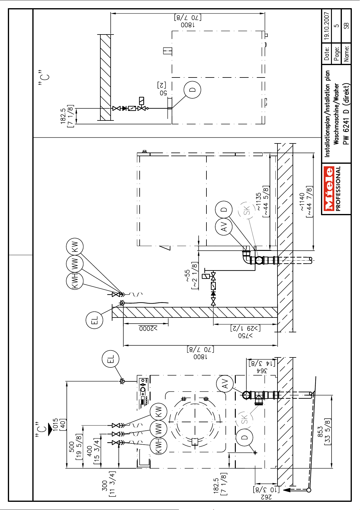
Direct steam (page 5)
Steam pressure (High pressure) ≤ 58 psi ≤58 psi
Boiling point (High pressure) ≤ 306 °F ≤ 152 °C
Heating capacity (High pressure) 86 kW 86 kW
Steam supply capacity (High pressure) 308 lbs/h 140 kg/h
Steam pressure (Low pressure) ≤7.25 psi ≤7,25 psi
Boiling point (Low pressure) ≤84 °F ≤120 °C
Heating capacity (Low pressure) 29 kW 29 kW
Steam supply capacity (Low pressure) 99.2 lbs/h 45 kg/h
Connection thread (on-site) 3/4" MPT 3/4" MPT
Steam
connection
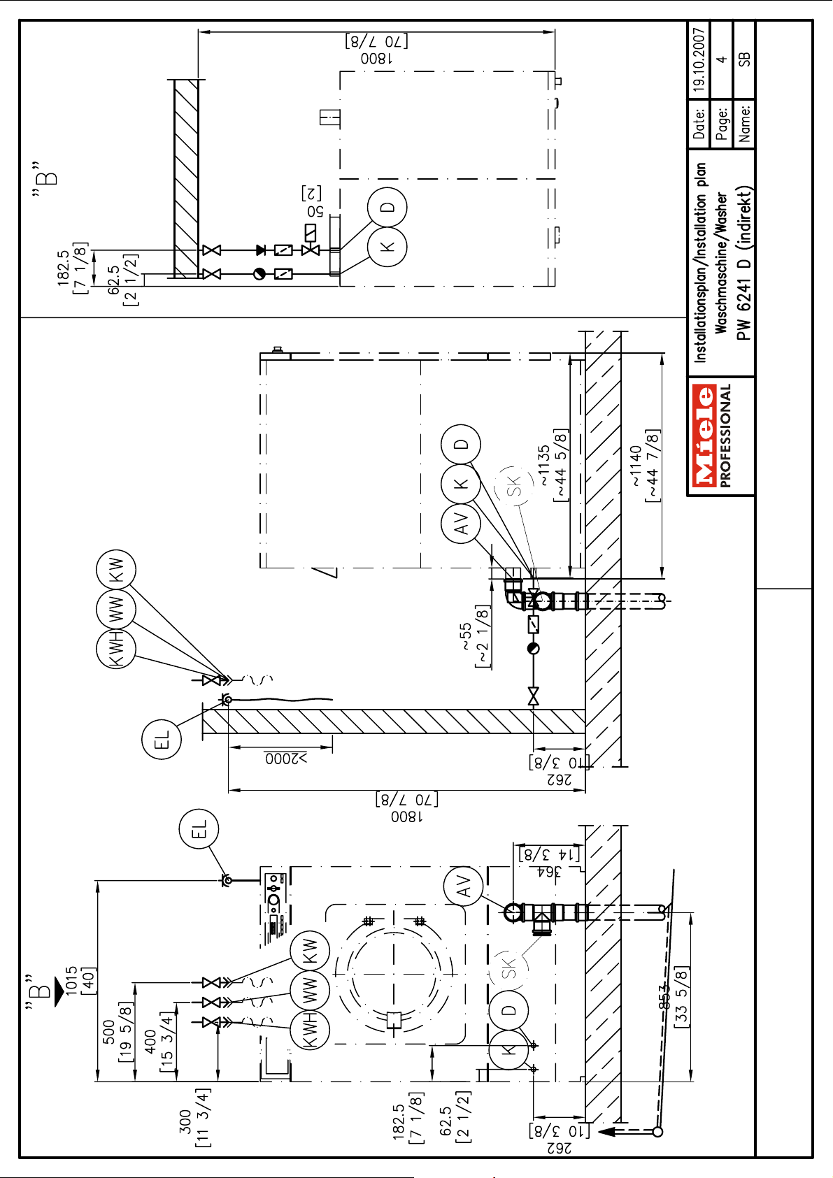
Indirect steam (page 4)
Steam pressure 58 - 145 psi 58 - 145 psi
Steam pressure on dryer version 58 - 72.5 psi 58 - 72,5 psi
Boiling point 306 - 363 °F 152 - 184 °C
Heating capacity 50 kW 50 kW
Steam supply capacity 185 lbs/h 84 kg/h
Connection thread (on-site) 1/2" MPT 1/2" MPT
Steam valve, steam filter and steam faucet must be
provided on-site.
Steam valve, steam filter, steam faucet and non-return
valve must be provided on-site.
USA CDN
On-site connection thread 1" MPT 1" MPT
Length of connection hose (supplied) 59 1/16" 1.500 mm
Water requirements (average 140°F [60°C] program)
Standard connection (with hot water connection) approx. 16.1 gal/h approx. 61 l/h
Additional requirements if hot water supply is not
Max. throughput 7.93 gal/min 30 l/min
On-site connection thread 1" MPT 1" MPT
Length of connection hose (supplied) 59 1/16" 1.500 mm
Water requirements (average for 140°F [60°C] program)
Standard connection (with hot water connection) approx. 15.3 gal/h approx. 58 l/h
Condensate
connection
Cold water
(Soft water)
Hot water
Note installation instructions for steam-heated Miele
washer-extractors.
Indirect steam (page 4)
Connection thread (on-site)
Steam valve, steam filter and steam faucet must be
provided on-site.
Min. flow pressure 14.5 psi 14,5 psi
Max. pressure 145 psi 145 psi
Max. throughput (if hot water supply is not available) 9.4 (21) gal/min 35.5 (80) l/min
available.
Max. temperature 158 °F 70 °C
Min. flow pressure 14.5 psi 14,5 psi
Max. pressure 145 psi 145 psi
If no hot water supply, connect hose to cold water!
1/2" MPT
1/2" MPT
Mains water
(Raw water)
Length of connection hose (supplied) 59 1/16" 1.500 mm
Water requirements (average for 140°F [60°C] program)
Standard connection (with hot water connection) approx. 57.9 gal/h approx. 219 l/h
Installation plan PW 6241 Steam
Date 19.10.2007 Page 8
(Optional)
Min. flow pressure 14.5 psi 14,5 psi
Max. pressure 145 psi 145 psi
Max. throughput 10.6 gal/min 40 l/min
On-site connection thread 1" MPT 1" MPT
If no raw water supply, connect hose to cold water!
Page 9

Drainage via
dump valve
Max. temperature 203 °F 95 °C
Machine drain connection (da × s × l) 3" x 1/16" x 4" 75 × 1,9 × 100 mm
On-site drain connection (d
Max. throughput 52.8 gal/min 200 l/min
Vented drainage required. If ventilation is insufficient, fit
Miele kit, Mat. no. 05238090.
Drain manifolds serving several machines must be of
sufficient cross-section.
USA CDN
) 3" 75 mm
i
Foam vent A drainage system for foam escaping from the drain
(supplied) 2 × screws (Diameter × length)
Machine must be secured! 5/8" x 3 9/16" 16 × 90 mm
Fixing materials provided for securing to concrete floor
4 × screws (Diameter × length) 1/2“ x 3 9/16“ 12 × 90 mm
4 × wall anchors (Diameter × length) 5/8“ x 3 9/16“ 16 × 90 mm
Machine must be secured!
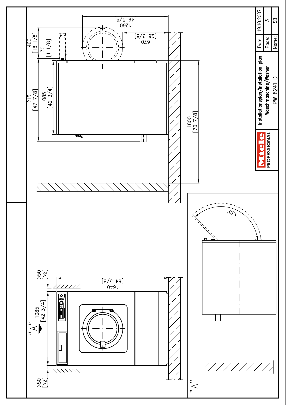
Machine data Width 42 11/16" 1.085 mm
Depth 48 1/4” 1.225 mm
Height 64 9/16" 1.640 mm
Knocked-down dimensions (Width) 42 15/16” 1.090 mm
Recommended clearance to rear wall
Net weight 1,410 lbs 640 kg
Dynamic floor load during operation, max. 8,417 N 8.417 N
Static load, max. 7,036 N 7.036 N
Dynamic load max. 1,353 N 1.353 N
Drum frequency, max. 18.3 Hz 18,3 Hz
Average heat dissipation
2 × wall anchors (Diameter × length) 1/2" x 3 9/16" 12 × 90 mm
Special product
WI:
vent can be built using standard drain pipe sections.
A 87° branch with an end cap should be provided for
this purpose.
Without plinth Fittings
Without plinth
Fixing materials provided for securing to concrete floor
(to machine front edge)
(depending on room temperature and selected program)
70 7/8" 1.800 mm
1,306 W 1.306 W
Installation should only be carried out by authorized installers in accordance with all local and national regulations!
Observe installation instructions when installing machine! All rights reserved!
Installation plan PW 6241 Steam
Date 19.10.2007 Page 9
 Loading...