

Installation plan
Washer-extractor
PW 6207 G
en - GB
12.13 M.-Nr. 09 868 210 / 01

2
M.-Nr. 09 868 210 / 01
Installationsplan / Installation plan
Waschmaschine / Washer
PW 6207 G

Installationsplan / Installation plan
Waschmaschine / Washer
PW 6207 G

A - A
Installationsplan / Installation plan
Waschmaschine / Washer
PW 6207 G

Installationsplan / Installation plan
Waschmaschine / Washer
PW 6207 G

Installationsplan / Installation plan
Waschmaschine / Washer
PW 6207 G

Technical data sheet
Washer-extractor:
Heating type:
PW 6207
Gas (G)
Legend:
Circled, bold-type abbreviations:
Connection required
en - GB
Abbreviations surrounded by broken circle:
Connection optional or required, depending on model
UM
Miele plinth
UG/UO 6020
(UG = Box plinth/UO = Open plinth)
Height/Type
mm
240
Width UG (UO)
mm
920 (900)
Depth UG (UO)
mm
1049 (1009)
BS
Concrete platform
Concrete platform (min. grade B15)
Recommended height
mm
240 Minimum height
mm
100
Recommended width
mm
920
Recommended depth
mm
1020
Good bond to floor is important!
Electrical
connection
1. Standard voltage (standard version)
V 3N AC 380-415
Frequency
Hz
50
Connected load
kW
4.4
Fuse rating
A 3 × 16
Connection cable, min. gauge
mm²
5 × 1.5
Cable grommet
M 20 x 1.5
It is always recommended to make electrical connection in
accordance with IEC 60309 via a plug and socket so that
electrical safety checks, e.g. during repair or service work,
can be carried out easily. For hard-wired connections install a
mains isolator device as per IEC 60947. The socket must be
accessible after machine installation. In order to increase
safety, the installation of an earth leakage circuit breaker is
recommended. In such case, an interrupter sensitive to all
voltages is necessary.
If necessary, equipotential bonding with good galvanic contact
must be guaranteed in compliance with all applicable local
and national installation codes.
Gas connection
Natural gas
On-site threaded union
Inch
½" female thread
Rated heat load
kW
34
Minimum connection pressure (may vary in other
countries)
Pa
1700
Length of connection hose (included)
mm
350
Liquid gas
On-site connection (Ermeto socket)
DN
12
Minimum connection pressure (may vary in other
countries)
Pa
2800 - 5750
Length of connection hose (included)
mm
350
Options / Accessories:
Machine connections:
Installationsplan / Installation plan: PW 6207 G
Datum / Date: 25.11.2013 Seite / Page: 8

The gas stopcock is provided by Miele. A shut-off valve
should be provided on site.
c.f. installation instructions for gas-heated washer-extractors.
Local building and plumbing codes must also be observed.
Cold water
(softened water)
Minimum flow pressure
kPa
100
Maximum pressure
kPa
1000
Max. flow rate (in absence of hot water)
l/min
26 (42)
On-site threaded union in accordance with DIN 44991 (flat
sealing)
Inch
¾" male thread
Length of connection hoses
(2 hoses + Y-piece included)
mm
1500
Water requirement (60°C programme = average value)
Standard connection (with hot water connection)
l/h
approx. 125
In the absence of a hot water supply, add sufficient water to
reach the required amount.
Hot water
(softened water)
Maximum temperature
°C
70
Minimum flow pressure
kPa
100
Maximum pressure
kPa
1,000
Max. flow rate
l/min
16
On-site threaded union in accordance with DIN 44991 (flat
sealing)
Inch
¾" male thread
Length of connection hose (1 connection hose included)
mm
1500
Water requirement (60°C programme = average value)
Standard connection (with hot water connection)
l/h
approx. 126
In the absence of hot water, connect hose to cold water!
Cold water
(raw water)
(optional)
Minimum flow pressure
kPa
100
Maximum pressure
kPa
1000
Max. flow rate
l/min
32
On-site threaded union in accordance with DIN 44991 (flat
sealing)On-site threaded union in accordance with DIN 44991
(flat sealing)
Inch
¾" male thread
Length of connection hoses
(2 hoses + Y-piece included)
mm
1500
Water requirement (60°C programme = average value)
Standard connection (with hot water connection)
l/h
approx. 72
If connecting to raw water, subtract water requirement from
cold water.
In the absence of raw water, connect hose to cold water!
Exhaust gas
Natural gas heating
Rated heat load
kW
34
Waste gas connection (int dia x wall thickness x l) [DN
150]
mm
150 x 1 x 300
Exhaust gas emissions at nominal heat load
g/s
32.1
Exhaust temperature at nominal heat load
°C
110
CO2 concentration at nominal heat load
%
Approx. 4.0
Liquid gas heating
Rated heat load
kW
34
Exhaust gas connection (int dia x wall thickness x l) [DN
150]
mm
150 x 1 x 300
Exhaust gas emissions at rated heat load
g/s
35.3
Exhaust gas temperature at rated heat load
°C
100
CO2 concentration at rated heat load
%
Approx. 4.0
Atmospheric burner with integrated flow control, Type: B
11BS
c.f. installation instructions for gas-heated washer-extractors.
Local building and plumbing codes must also be observed.
A safe distance should be maintained between combustible or
non-heatproof items and the exhaust gas duct.
Installationsplan / Installation plan: PW 6207 G
Datum / Date: 25.11.2013 Seite / Page: 9

Drainage, version
with dump valve
Maximum temperature
°C
95
Waste water connection on machine (ext dia × wall thickness
× l) [DN 70]
mm
75 × 1.9 × 95
On-site drain connection (di) [DN 70 sleeve]
mm
75
Max. transient flow rate
l/min
200
Vented collector line required; if insufficient venting, use Miele
installation kit, Mat. no. 05238090.
When several machines are connected, ensure that the
manifold is of a sufficient diameter.
Foam venting
In the event of heavy foaming, foam may be released from
the air vent. In order to dispose of this foam, drainage
pipework with an odour trap can be built on site using
standard pipe sections of a suitable diameter. This generally
involves the use of an 87° branch-off with a cap.
Floor anchors
(supplied)
Miele UG/UO 6020 plinths
4 x metal angle brackets (to secure machine to plinth)
4 × wood screws DIN 571 (Ø × length)
mm
12 × 90
4 × rawl plugs (Ø × length)
mm
16 × 80
The machine must be secured!
Anchors for a floating screed floor must be provided on site.
On concrete platform
4 × wood screws DIN 571 (Ø × length)
mm
12 × 90
4 × rawl plugs (Ø × length)
mm
16 × 80
The machine must be secured!
Anchors for a floating screed floor must be provided on site.
Without plinth
4 × wood screws DIN 571 (Ø × length)
mm
12 × 90
4 × rawl plugs (Ø × length)
mm
16 × 80
The machine must be secured!
Anchors for a floating screed floor must be provided on site.
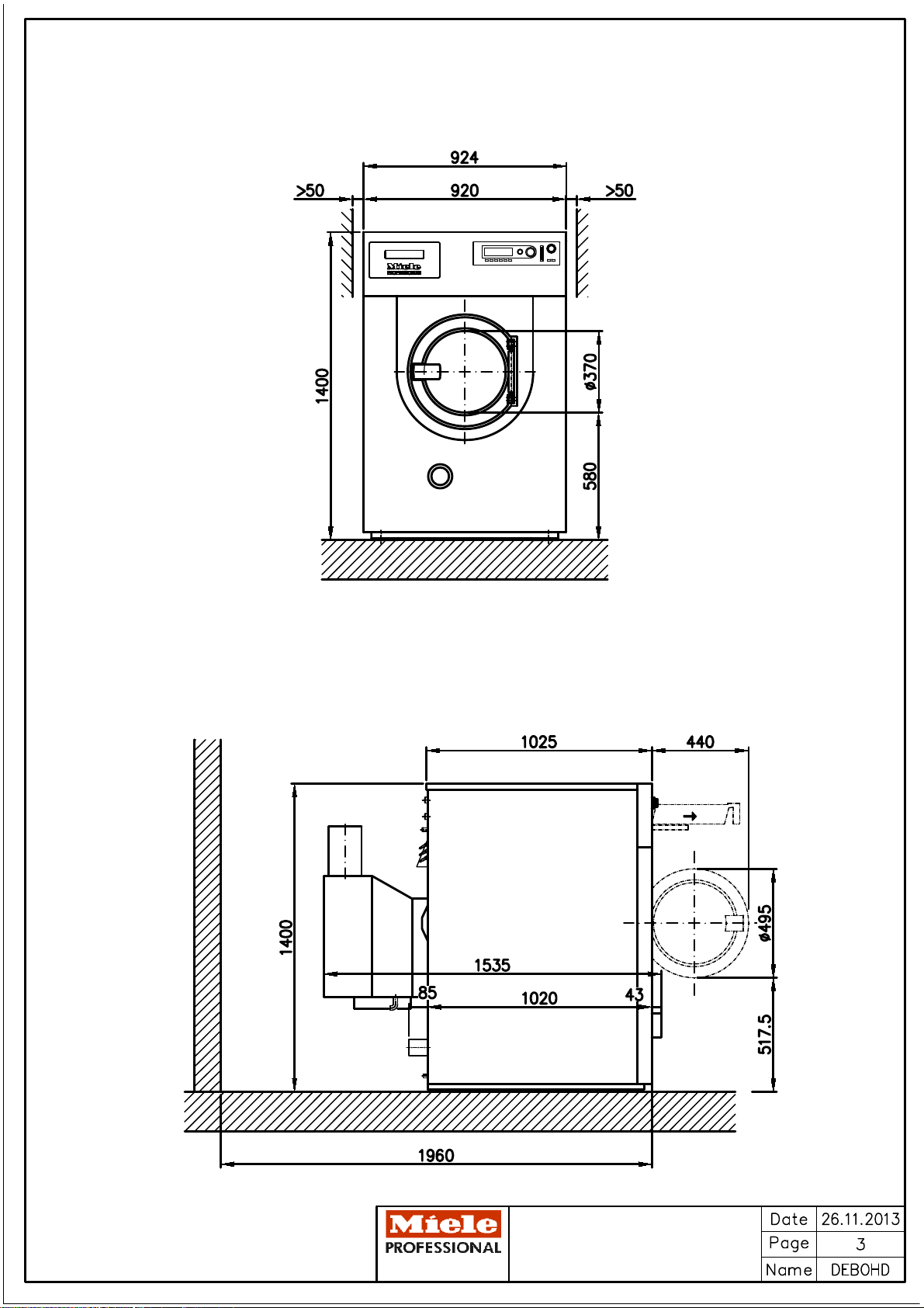
Machine data
Width
mm
924
Depth
mm
1535
Height
mm
1400
Min. access width
mm
930
Recommended distance from opposite wall (to front of
machine)
mm
1965
Net weight
kg
589
Max. floor load in operation
N
6978
Max. static floor load
N
6445
Max dynamic floor load
N
533
Max. drum rotation frequency
Hz
18.3
Average heat dissipation to installation site
(depending on ambient temperature and programme
selected)
W
N/A
Installation should only be performed by qualified fitters in accordance with valid regulations, relevant standards and health
and safety codes!
It is important to comply with installation instructions when installing machines! All rights reserved! Dimensions in mm.
Installationsplan / Installation plan: PW 6207 G
Datum / Date: 25.11.2013 Seite / Page: 10
 Loading...