

Page 1
Installation plan
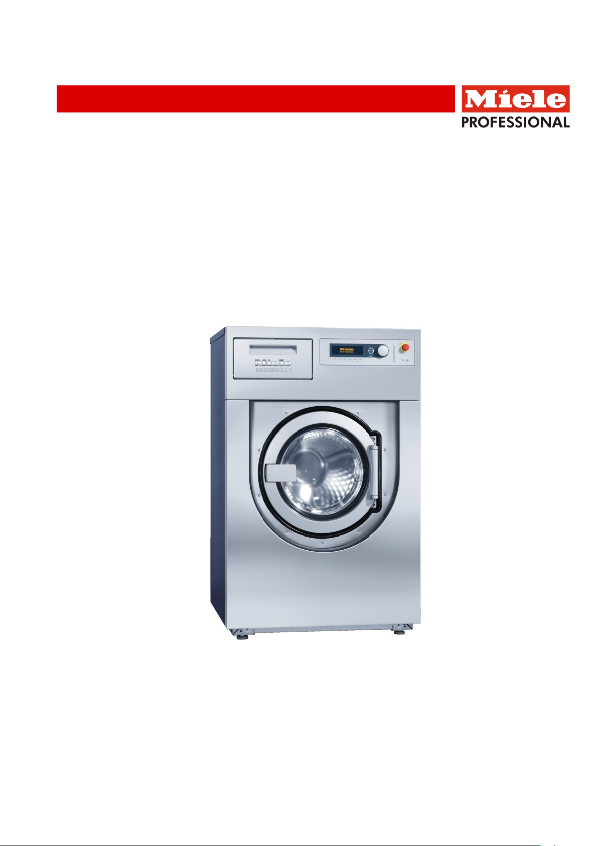
Washer
PW 6137 EL (Electrically heated)
en - US
12.15 M.-Nr. 09 284 470 / 02
Page 2

M.-Nr. 09 284 470 / 02
2
Page 3
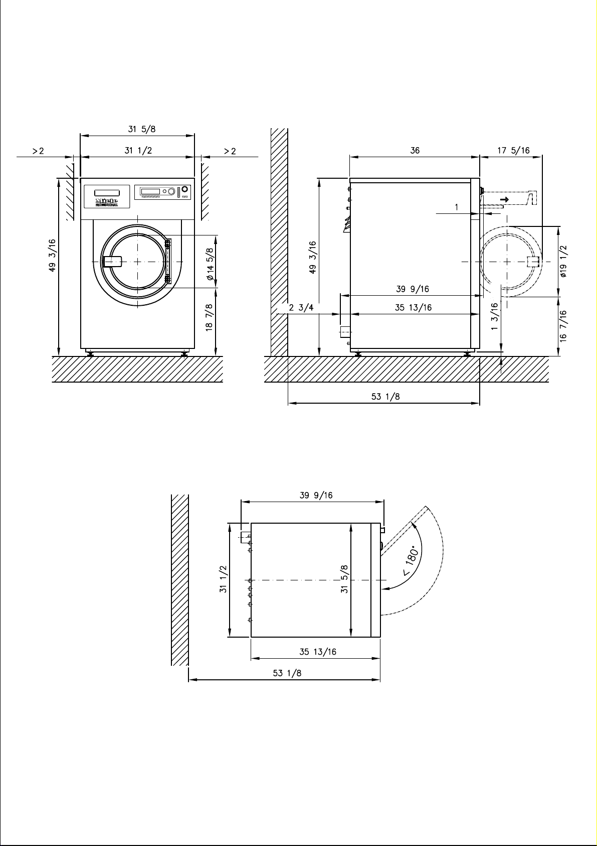
PW 6137 EL (measurements in inches)
3
Page 4
4
PW 6137 EL (measurements in inches)
Page 5

5
PW 6137 EL (measurements in inches)
Page 6

6
PW 6137 EL (measurements in inches)
Page 7

PW 6137 EL (measurements in millimeters)
7
Page 8

8
PW 6137 EL (measurements in millimeters)
Page 9

9
PW 6137 EL (measurements in millimeters)
Page 10

10
PW 6137 EL (measurements in millimeters)
Page 11

Washer-extractor:
PW 6137
UO 6013 (UO = Open base)
Height
5 11/16“
144 mm
Width
30 11/16“
780 mm
Depth
35 3/8“
899 mm
UG 6013 (UG = closed base)
Height
5 11/16“
144 mm
Width
31 ½“
800 mm
Depth
35 13/16“
909 mm
UO 6013-30 (UO = Open base)
Height
11 13/16“
300 mm
Width
30 11/16“
780 mm
Depth
35 3/8“
899 mm
UG 6013-30 (UG = closed base)
Height
11 13/16“
300 mm
Width
31 01/2“
800 mm
Depth
35 13/16“
909 mm
Concrete base
Recommended height
5 15/16“
150 mm
Minimum height
3 15/16“
100 mm
Minimum width
37 3/8“
950 mm
Minimum depth
39 3/8“
1000 mm
External dispensing pumps (2 or 4 head pump):
Voltage (external power supply required)
120V
Fusing
15A
Supplied with supply cable and plug
NEMA 5-15
V
3 AC 220-240V
Hz
60
kW
17 kW
A
3 × 50
4 x AWG 6
4 x 10 mm²
V
3 AC 208V
Hz
60
kW
14.3 kW
A
3 × 50
4 AWG 6
4 x 10 mm²
Technical Datasheet
Heating:
Legend:
Optional extras:
UG/
Miele base
UO
Solid circle around symbol:
Connection mandatory
Broken circle around symbol:
Connection optional or as required
Electric (EL)
en - US
BS
Dispensing
pump
Machine connections:
Electrical
connection
1. Standard voltage (as supplied)
2. Standard voltage (convertible)
Frequency
Rated load
Fuse rating
Connection cable, min. cross-section
(Connection cable not included)
Frequency
Rated load
Fuse rating
Connection cable, min. cross-section
(Connection cable not included)
Technical datasheet: PW 6137 EL (electrically heated)
Date: 03.2015 Page: 11
Page 12

Sleeve with external thread
3/8 x 1 3/8“
10 × 35 mm
for washer and nut
M 10
OS machine version.
If necessary, equipotential bonding with good galvanic
Min. water pressure/flow pressure
14.5 psi
100 kPa
Max. water pressure/flow pressure
145 psi
1000 kPa
Max. throughput
6.9 gal/min
26 l/min
Max. throughput (if hot or raw water supply is not available)
11 gal/min
42 l/min
2 inlet hoses with ¾" threaded union (female)
On-site connection thread
Inch
¾“ garden hose
thread, male
Length of inlet hose
59 1/16“
1500 mm
Hourly water demand (average for 60°C cotton program)
determined at cold, hot and raw water connection
Approx. 23.5
gal/h
Approx. 89 l/h
ment, if there is no hot water supply available.
Max. water temperature
158°F
70°C
Min. water pressure/flow pressure
14.5 psi
100 kPa
Max. water pressure/flow pressure
145 psi
1000 kPa
Max. throughput
4.2 gal/min
16 l/min
1 inlet hose with ¾" threaded union supplied.
On-site connection thread
Inch
¾" garden hose
Length of inlet hose
59 1/16“
1500 mm
determined at cold, hot and raw water connection
Approx. 24.6
Approx. 93 l/h
If hot water is not available, connect hot water hose to cold
(Option)
Min. water pressure/flow pressure
14.5 psi
100 kPa
Max. water pressure/flow pressure
145 psi
1000 kPa
Max. throughput
8.5 gal/min
32 l/min
(female)
On-site connection thread
Inch
¾“ garden hose
thread, male
Length of inlet hose
59 1/16“
1500 mm
Hourly water demand (average for 60°C cotton program)
Approx. 15.5
Approx. 55 l/h
Electrical connection must comply with national regulations.
Connection using multi-pole lockable wall socket in compliance with IEC/EN 60309 and IEC/EN 60947 is recommended in order to simplify electrical tests. If machines are hardwired, a multi-pole mains switch must be provided on site.
Switches with a contact gap of more than 3 mm can be
used. These include switches, fuses and contactors (IEC/EN
60947). A wall socket or mains isolator must be easily accessible after installation.
Reinstallation of the supply point, changes to the equipment
or checks on the protective conductor, including determination of correct fuse rating, should only be performed by a
properly trained electrician.
If necessary, equipotential bonding with good galvanic
contact must be provided in accordance with all appropriate
national and local regulations.
Equipotential
bonding
(Option)
Cold water
(soft water)
Fitting such as washers and nuts are only supplied with the
contact must be provided in accordance with all appropriate
national and local regulations.
Hot water
(soft water)
Cold water
(hard water)
Add the hot water requirement to the cold water require-
If connected to hard water supply, subtract cold water (soft)
volume.
Hourly water demand (average for 60°C cotton program)
water valve!
Optional retrofit kit: 2 inlet hoses with ¾" threaded union
thread, male
gal/h
determined at cold, hot and hard water connection)
Technical datasheet: PW 6137 EL (electrically heated)
Date: 03.2015 Page: 12
gal/h
Page 13

(Option)
Min. water pressure/flow pressure
14.5 psi
100 kPa
Max. water pressure/flow pressure
145 psi
1000 kPa
Max. throughput
1.5 gal/min
5.5 l/min
1 inlet hose with ¾" threaded union included (optional).
On-site connection thread
Inch
¾" garden hose
thread, male
Length of inlet hose
59 1/16“
1500 mm
Max. waste water temperature
203°F
95°C
Waste water connection on machine (ext. diameter)
2 15/16“
75 mm [DN 70]
Drain connection on site (int. diameter)
2 15/16“
75 mm [DN 70]
Max. transient throughput
52.9 gal/min
200 l/min
Without base
The machine must be firmly anchored to the floor!
Anchor fittings included:
2 × angle brackets (from shipping lock)
2 × bolts DIN 571 (Ø × length)
5/16 x 3 1/8“
8 x 80 mm
2 × rawl plugs (Ø × length)
½ x 2 3/8“
12 x 60 mm
On concrete base
The machine must be firmly anchored to the floor!
Anchor fittings included:
2 × angle brackets (from shipping lock)
2 × bolts DIN 571 (Ø × length)
5/16 x 3 1/8“
8 x 80 mm
2 × rawl plugs (Ø × length)
½ x 2 3/8“
12 x 60 mm
Miele base
The base must be firmly anchored to the floor!
Anchor fittings included with plinth:
4 × bolts DIN 571 (Ø × length)
5/16 x 3 1/8“
8 x 80 mm
4 × rawl plugs (Ø × length)
½ x 2 3/8“
12 x 60 mm
Machine data
Machine width
31 5/8“
804 mm
Machine depth
39 9/16“
1005 mm
Machine height
49 3/16“
1250 mm
Casing width
31 ½“
800 mm
Casing depth
35 13/16“
910 mm
Min. width of delivery access to installation site
31 7/8“
810 mm
Recommended rear wall gap (measured to front of machine)
53 1/8“
1350 mm
Minimum rear wall gap (measured to rear of machine lid)
15 ¾“
400 mm
Net weight
751 lb
340.6 kg
Dynamic floor load, max.
4290 N
4290 N
Static floor load, max.
3778 N
3778 N
Dynamic load, max.
503 N
503 N
Drum frequency, max.
18,3 Hz
18,3 Hz
Average heat dissipation
5016 BTU/h
1.47kW
Sound pressure level (re 20 mPA),
69 dB (A
69 dB (A)
Cold water
Liquid
dispensing
Waste water
Drain valve
Fittings
Vented drainage required. If ventilation is insufficient, fit Miele
kit, Mat. no. 05238090.
Drain manifolds serving several machines must be of sufficient cross-section.
The floor must be solid and able to support the machine. The
fittings included are suitable for a solid concrete floor. Anchor
bolts and fittings for other floor types must be provided on
site.
The grade of concrete should be suitable for the load. The
base should be firmly anchored to the floor to accommodate
dynamic stress!
Both the machine and the base must be installed according to
the installation instructions provided.
(dependent on ambient room temperature and program selected)
workplace-related
(at distance of 1 m and height of 1.6 m)
Installation should only be carried out by authorized installers in accordance with valid regulati ons!
Follow installation instructions when installing machine! All rights reserved!
Technical datasheet: PW 6137 EL (electrically heated)
Date: 03.2015 Page: 13
 Loading...