

Page 1
Installation plan
Heat-pump dryer
Installatieschema
Warmtepompdroger
PT 8337 WP
nl - NL
en - GB
08.11 M.-Nr. 09 108 880 / 02
Page 2

2
Lees beslist de gebruiks- en montagehandleiding voordat u uw
apparaat plaatst, installeert en in gebruik neemt.
Dat is veiliger voor uzelf en u voorkomt schade aan uw apparaat.
Technische wijzigingen voorbehouden
It is essential to read the operating and installation instructions before
installing, commissioning or using the machine.
This avoids the risk of accidents or damage.
All rights reserved
M.-Nr. 09 108 880 / 02
Page 3
Page 4
Page 5

Page 6

Page 7

Page 8

Technical datasheet
Tumble dryer:
Heating:
PT 8337 WP
Electric (EL)
Legend:
Abbreviations in bold type:
Connection required
en - GB
Abbreviations in circle with dashes:
Connection optional or required depending on model version
BS
Concrete plinth
Quality and density of concrete must comply with load.
Concrete plinth must be firmly secured to floor!
Recommended height
mm
100
Minimum height
mm
50
Width min.
mm
1050
Depth:min.
mm
1400
Electrical
connection
1. Standard voltage (as supplied)
V 3N AC 380 - 415
Frequency
Hz
50
Rated load
kW
5.2
Fuse rating
A 3 × 16
Connection cable, min. cross-section
mm²
5 × 1.5
Cable screw connector
M 16
Connection cable (to be ordered
separately)
Electrical connection must comply with national regulations.
Connection using multi-pole wall socket in compliance with
IEC/EN 60309 and IEC/EN 60947 is recommended in order to
simplify electrical tests.
If machines are hard-wired, a multi-pole mains switch must be
provided on site.
A wall socket or mains isolator must be accessible after
installation.
Peak load energy
management
Control contact voltage
V
AC 230
Connection cable, min. cross-section
mm²
5 × 1.5
Connection cable (to be ordered separately)
Connection via a flexible supply lead with a separate isolator
is recommended. The isolator should be visible and easily
accessible after machine installation.
Condensate
drainage
Machine-side drain connection (ext. diameter) mm 75 [DN 70]
mm
40 [DN 40]
Heat-pump dryers operate on the principle of condensation.
Condensate is drained off separately via a floor drain.
Condensate can be fed off to the floor drain using a hose or
pipe.
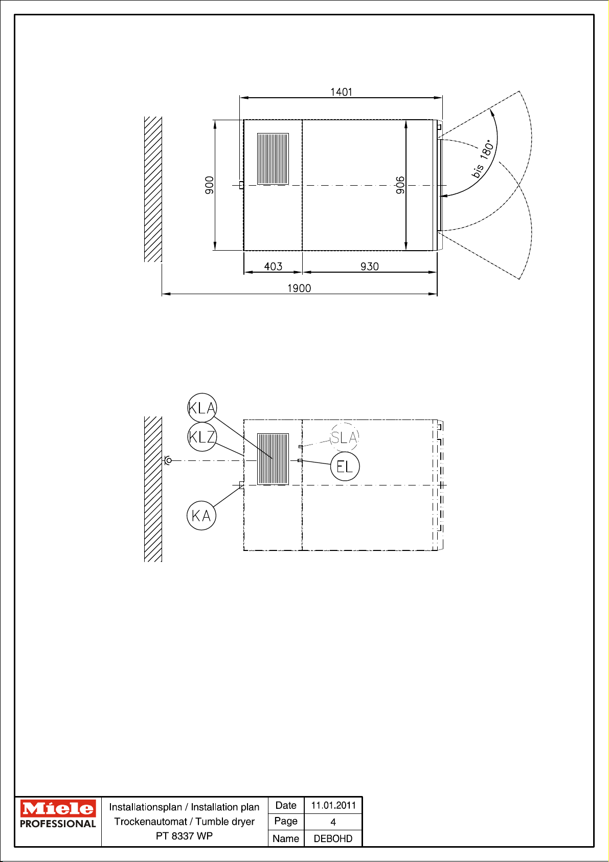
N
Optional extras:
Machine connections:
Installationsplan / Installation plan: PT 8337 WP
Datum / Date: 01.08.2011 Seite / Page: 7
Page 9

Cooling air intake
Vents for the provision of cooling air must remain unobstructed.
Cooling air outlet
Vents for the provision of cooling air must remain unobstructed.
During cooler operation, transient waste air temperatures of
up to 60°C may occur. Hence, only heat-resistant materials
should be used close to the outlet vent.
Fittings (supplied)
On concrete platform
2 × clamps
2 × screws DIN 571 (Ø × length)
mm
6 × 40
2 × rawl plugs (Ø × length)
mm
10 × 50
Machine must be bolted to the floor!
Fixing materials for a floating screed floor are to be provided
on site.
Without plinth
2 × clamps
2 × screws DIN 571 (Ø × length)
mm
6 × 40
2 × rawl plugs (Ø × length)
mm
10 × 50
The machine should be bolted to the floor.
Fixing materials for a floating screed floor are to be provided
on site.
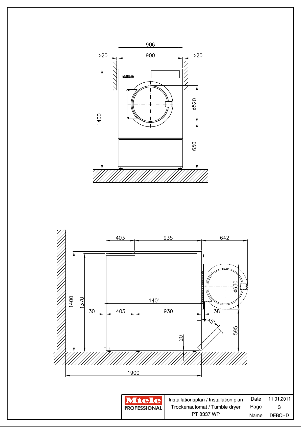
Machine data
Machine width (total installation)
mm
906
Machine depth (total installation)
mm
1401
Machine height (total installation)
mm
1400
Casing width
mm
900
Casing depth (dryer module)
mm
930
Casing depth (heat pump module)
mm
403
Minimum width of delivery access to installation site
mm
920
Recommended rear wall gap (measured to front of machine)
mm
1900
Min. wall gap (to rear edge of lid)
mm
500
Net weight
kg
314.5
Average heat dissipation
(dependent on ambient room temperature and programme
selected)
W
1.300
A Noise level
dB (A)
72.2
A Sound pressure level
(measured at a distance of 1 m from the machine and at a
height of 1.6 m)1 m
dB (A)
58
Ambient temperature at installation site to ensure optimum
heat pump operating conditions.
°C
15 - 43
If the ambient temperature is permanently above 45°C,
cooling or room ventilation is recommended.
Installation should only be carried out by authorised fitters in accordance with valid regulations!
Observe installation instructions when installing machine! All rights reserved! Measurements in mm.
Installationsplan / Installation plan: PT 8337 WP
Datum / Date: 01.08.2011 Seite / Page: 8
Page 10

Technische gegevens
Droogautomaat:
Verwarmingssoort:
PT 8337 WP
Elektrisch (EL)
Legenda:
Geheel omcirkelde afkortingen betekenen:
aansluiting vereist
nl - NL
Niet geheel omcirkelde afkortingen betekenen:
optioneel of afhankelijk van het apparaat is aansluiting vereist
BS
Betonnen sokkel
De betonsoort en de stevigheid moeten geschikt zijn voor de
belasting die de automaat uitoefent. Een aanwezige betonnen
sokkel moet goed aan de ondergrond hechten!
Hoogte aanbevolen
mm
100
Hoogte minimaal
mm
50
Breedte minimaal
mm
1.050
Diepte minimaal
mm
1.400
Elektrische
aansluiting
1. Standaardspanning (af fabriek)
V 3N AC 380 - 415
Frequentie
Hz
50
Aansluitwaarde
kW
5,2
Zekering
A 3 × 16
Aansluitkabel, draaddoorsnede, minimaal
mm²
5 × 1,5
Kabelwartel
M 16
De aansluitkabels worden niet bijgeleverd.
De elektrische aansluiting dient volgens de nationale en
plaatselijke voorschriften te worden uitgevoerd.
Het is aan te bevelen het apparaat op een vergrendelbare
contactdoos aan te sluiten (volgens NEN-EN-IEC 60309 en
NEN-EN-IEC 60947) waarmee het apparaat met alle polen
van de netspanning kan worden losgekoppeld, zodat de
elektrische veiligheid eenvoudig kan worden gecontroleerd.
Bij een vaste aansluiting moet men alle polen via de installatie
kunnen loskoppelen.
De contactdoos of de schakelaar moet ook na de plaatsing
van het apparaat zichtbaar en goed toegankelijk zijn.
Piekbelastings-
schakelaar
Aansluitspanning contacten (besturing)
V
AC 230
Aansluitkabel, draaddoorsnede, minimaal
mm²
5 × 1,5
De aansluitkabels worden niet bijgeleverd.
Het is aan te bevelen de aansluiting met een flexibele
aansluitleiding te realiseren, met een extra mogelijkheid tot
loskoppelen. Het scheidingssysteem (schakelaar) moet na de
plaatsing van het apparaat zichtbaar en goed toegankelijk
zijn.
Condensafvoer
Condenstuit machinekant (buitendiameter) mm 75 [DN 70]
mm
40 [DN 40]
Een droogautomaat met warmtepomp werkt volgens het
condensprincipe. Het condenswater moet apart via een
vloerafvoer worden afgevoerd.
De condensafvoer kan plaatsvinden via een slang of buis
(met verval) naar de vloerafvoer.
KA
Opties/toebehoren:
Aansluitingen:
Installationsplan / Installation plan: PT 8337 WP
Datum / Date: 01.08.2011 Seite / Page: 7
Page 11

Koellucht toevoer
Houd openingen voor de koelluchtvoorziening vrij.
Koellucht afvoer
Houd openingen voor de koelluchtvoorziening vrij.
Als het regelcircuit (nakoeler) in bedrijf is, kan de afgevoerde
lucht kortstondig een temperatuur bereiken van max. 60°C.
Gebruik in de buurt van de afvoeropening daarom alleen
hittebestendige materialen.
Bevestiging
(bijgeleverd)
Op betonnen sokkel
2 bevestigingsprofielen
2 houtschroeven DIN 571 (Ø × lengte)
mm
6 × 40
2 pluggen (Ø × lengte)
mm
10 × 50
De machine moet beslist worden bevestigd!
Bevestigingsmateriaal voor speciale vloeren (bijv. met
geïsoleerde afdeklaag) wordt niet bijgeleverd.
Zonder sokkel
2 bevestigingsprofielen
2 houtschroeven DIN 571 (Ø × lengte)
mm
6 × 40
2 pluggen (Ø × lengte)
mm
10 × 50
Het is aan te bevelen de machine te bevestigen.
Bevestigingsmateriaal voor speciale vloeren (bijv. met
geïsoleerde afdeklaag) wordt niet bijgeleverd.
Gegevens
machine
Machinebreedte (complete installatie)
mm
906
Machinediepte (complete installatie)
mm
1.401
Machinehoogte (complete installatie)
mm
1.400
Breedte behuizing
mm
900
Diepte behuizing (droogmodule)
mm
930
Diepte behuizing (warmtepompmodule)
mm
403
Breedte transportopening min. (binnenwerks)
mm
920
Aanbevolen afstand tot de wand (tot voorkant apparaat)
mm
1.900
Minimale afstand tot de wand (tot achterkant deksel)
mm
500
Nettogewicht
kg
314,5
Gemiddelde warmteafgifte aan de ruimte
(afhankelijk van omgevingstemperatuur en gekozen
programma)
W
1.300
A-gewogen geluidsvermogen
dB (A)
72,2
A-gewogen geluidsdruk, werkplekspecifiek
(afstand 1 m, hoogte 1,6 m)
dB (A)
58
Omgevingstemperatuur op de plaats van opstelling (voor een
optimale werking van de warmtepomp)
°C
15 - 43
Ligt de omgevingstemperatuur continu boven 45°C, dan
verdient het aanbeveling het vertrek extra te
koelen/ventileren.
De installatiewerkzaamheden mogen alleen door een erkend installateur worden uitgevoerd met inachtneming van alle van
toepassing zijnde voorschriften en normen!
Houdt u zich bij plaatsing van het apparaat beslist aan de montagehandleiding! Wijzigingen voorbehouden! Afmetingen in
mm.
Installationsplan / Installation plan: PT 8337 WP
Datum / Date: 01.08.2011 Seite / Page: 8
 Loading...