

Page 1

Installation Instructions
Gas Cooktops
KM 342
KM 344
To prevent accidents and
machine damage,
read these instructions
before installation or use.
®
UV
M.-Nr.
®
05 649 320
Page 2
WARNING:
If the information in this manual is not followed
exactly, a fire or explosion may result causing
property damage, personal injury or death.
Do not store or use gasoline or other flammable
–
vapors and liquids in the vicinity of this or any
other appliance.
WHAT TO DO IF YOU SMELL GAS
–
ß Do not try to light any appliance.
ß Do not touch any electrical switch.
ß Do not use any phone in your building.
ß Immediately call your gas supplier from a
neighbor’s phone. Follow the gas supplier’s
instructions.
ß If you cannot reach your gas supplier, call the
fire department.
– Installation and service must be performed by a
qualified installer, service agency or the gas
supplier.
(In Massachusetts a licensed plumber/gasfitter)
–
Note to the installer:
Please leave this instruction book with the con
-
sumer for the local electrical/gas inspector’s use.
2
Page 3

Contents
Important safety instructions . . . . . . . . . . . . . . . . . . . . . . . . . . . . . . . . . . . . . . . . 4
Appliance dimensions. . . . . . . . . . . . . . . . . . . . . . . . . . . . . . . . . . . . . . . . . . . . . . 6
Installation . . . . . . . . . . . . . . . . . . . . . . . . . . . . . . . . . . . . . . . . . . . . . . . . . . . . . . . 8
Setting the cooktop into place . . . . . . . . . . . . . . . . . . . . . . . . . . . . . . . . . . . . . . . . . 8
Electrical connection. . . . . . . . . . . . . . . . . . . . . . . . . . . . . . . . . . . . . . . . . . . . . . 10
Wiring diagram . . . . . . . . . . . . . . . . . . . . . . . . . . . . . . . . . . . . . . . . . . . . . . . . . . . 11
Gas connection . . . . . . . . . . . . . . . . . . . . . . . . . . . . . . . . . . . . . . . . . . . . . . . . . . 12
Gas pressure regulator . . . . . . . . . . . . . . . . . . . . . . . . . . . . . . . . . . . . . . . . . . . . . 14
Nominal Rating Table. . . . . . . . . . . . . . . . . . . . . . . . . . . . . . . . . . . . . . . . . . . . . . . 15
Converting to LP gas. . . . . . . . . . . . . . . . . . . . . . . . . . . . . . . . . . . . . . . . . . . . . . 16
To convert the regulator: . . . . . . . . . . . . . . . . . . . . . . . . . . . . . . . . . . . . . . . . . . . . 16
To convert the burners . . . . . . . . . . . . . . . . . . . . . . . . . . . . . . . . . . . . . . . . . . . . . . 17
Changing the needle valves . . . . . . . . . . . . . . . . . . . . . . . . . . . . . . . . . . . . . . . . . 19
Changing the orifices. . . . . . . . . . . . . . . . . . . . . . . . . . . . . . . . . . . . . . . . . . . . . . . 20
Check the intake air . . . . . . . . . . . . . . . . . . . . . . . . . . . . . . . . . . . . . . . . . . . . . . . . 22
After conversion. . . . . . . . . . . . . . . . . . . . . . . . . . . . . . . . . . . . . . . . . . . . . . . . . . . 23
3
Page 4

Important safety instructions
Installation
The minimum distances given in
these Installation Instructions must
be observed in order to ensure safe
operation. Failure to do so increases
the risk of fire.
The countertop must be bonded
with heat resistant (212 °F/100 °C)
adhesive to prevent distortion or dis
solving.
-
fig. 1 recommended
Deep fat fryers must not be in
stalled next to gas cooktops. Gas
flames can ignite splattering oil. A distance of at least 12" (305 mm) should
be maintained between these two appliances. The mimimum distance between two cooktops must be 4"
(10 cm).
The cooktops should only be in-
stalled as shown in Figs. 1 & 2,
while maintaining the required safety
distances shown. Do not install the
cooktop between two tall cabinets as
this is a fire hazard.
a = minimum distance between
cooktop and a tall cabinet:
12" (300 mm)
Cooktops should not be installed
above a dishwasher, washer, dryer,
freezer or refrigerator. The heat gener
ated by cooktops could damage these
appliances.
-
fig. 2 possible but not recommended
fig.3 not allowed
4
Page 5

Important safety instructions
Gas appliances should only be in
stalled in a well ventilated area.
Install the appliance so that the
power cord or gas piping does not
come into contact with any portion of
the cooktop which may become hot
during use.
This appliance must be installed
with its own shut off valve and the in
cluded gas pressure regulator. Both
the valve and the regulator must be
easily accessible to the consumer to
turn on or shut off the gas supply af
ter the appliance is installed.
This appliance must be disconnected from the gas supply during
any pressure testing of that system
performed in excess of
1 / 2 psi
(3.5 kPa), or isolated at test pressures equal to or less than
1 / 2 psi
(3.5 kPa).
Any pipe connections must be made
using a thread sealant approved for
gas connections. Failure to correctly
install these items could lead to a
gas leak and subsequent explosion.
Safety distance above the appliances
-
-
As a general rule there must be at least
30 inches (762 mm) between the top of
the appliance and any cabinet above it,
b. If the cabinet manufacturer recommends a greater distance, follow that
manufacturer’s recommendation.
The maximum depth, c, of cabinets installed above a cooktop must not exceed 13" (330 mm).
When installing the cooktop under a
venting hood, always observe the minimum safety distance recommended by
the hood manufacturer.
Keep this instruction book in a safe
place for future reference and pass it
on to any future owner.
5
Page 6

Appliance dimensions
KM 342
3/8"
(9mm)
3 / 8 "
3
(86mm)
5/16"
21
(542mm)
36"
(914mm)
b
3 / 8 "
3
(86mm)
* max.R 3/16
(max.R4 mm)
a Built-in depth
"
3 / 4 "
2
(min.70mm)
35"
(889mm)
3 / 8 "
20
(518mm)
25"
(min.635mm)
1
7 / 8
”
(min.47mm)
6
Page 7
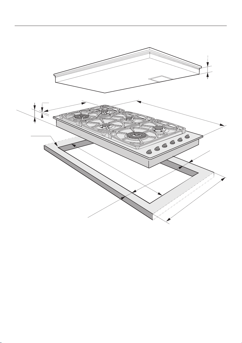
KM344
3/8”
(9mm)
3 / 8 "
3
(86mm)
* max.R 3/16"
(max.R4mm)
5 / 1 6 "
21
(542mm)
41
1 / 2 "
(1054mm)
Appliance dimensions
a
3/ 8"
3
(86mm)
1 / 2 "
42
(1079mm)
3 / 4 "
2
(min.70mm)
3 / 8 "
20
(518mm)
a Built-in depth
”
7 / 8
1
(min.47mm)
25”
(min.635mm)
7
Page 8
Installation
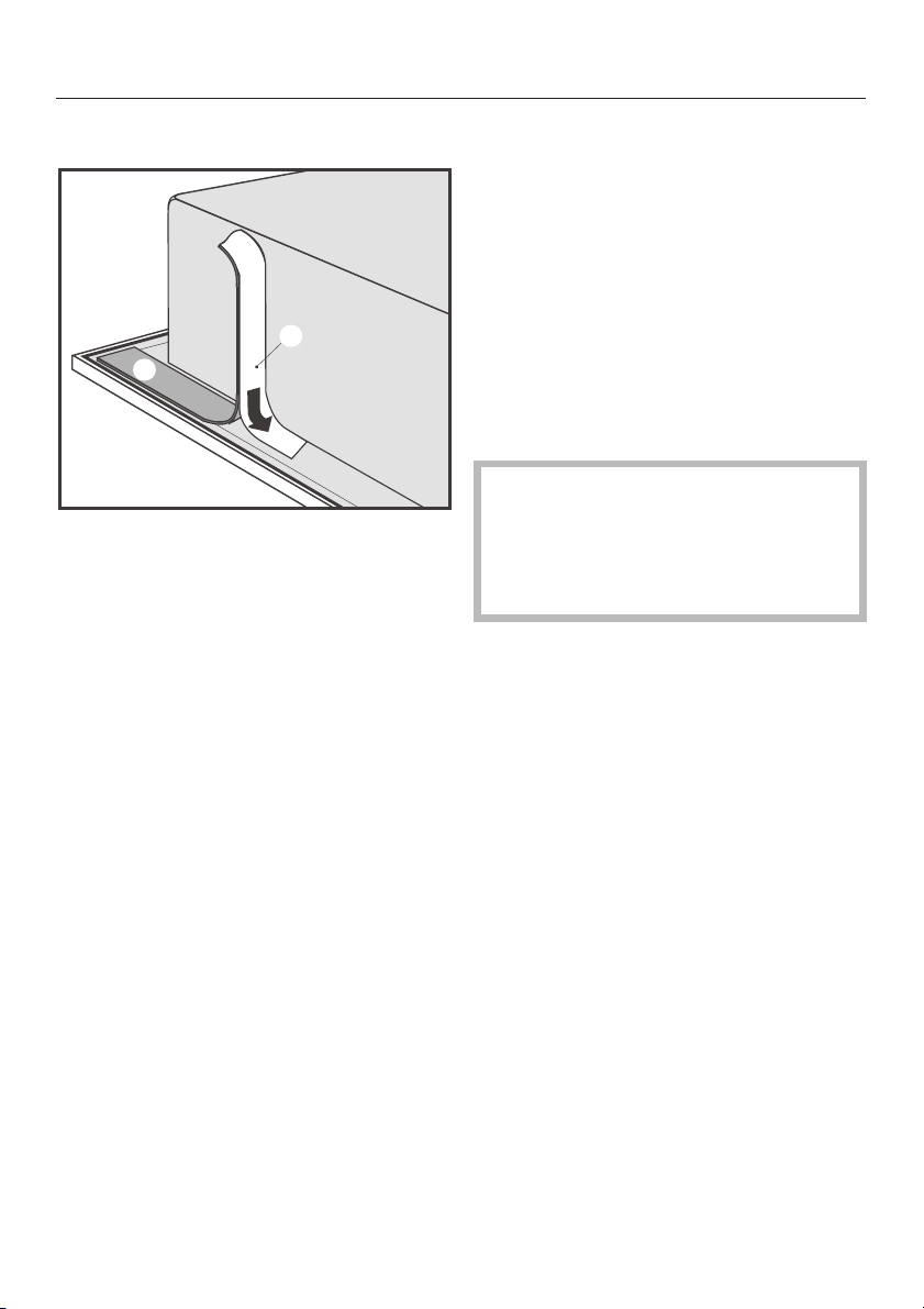
Setting the cooktop into place
e
d
Remove the protective backing, d,
^
from the seal, c, supplied and stick it
under the edge of the cooktop.
Screw the gas regulator onto the nip
^
ple at the rear of the cooktop. (See
"Gas Connection" for more guid
ance).
Feed the power cord through the
^
cut-out to the power outlet.
Set the cooktop in the cut-out and
^
center it.
Install the appliance so that the
power cord or gas piping does not
come into contact with any portion of
the cooktop which may become hot
during use.
-
-
8
Page 9

Installation
The cooktop must not be perma
nently sealed into the countertop
when installed.
If the cooktop is sealed into position,
the countertop or appliance could be
damaged if the cooktop needs to be re
moved for maintenance or service. The
sealing strip under the edge of the top
part of the cooktop provides a sufficient
seal for the countertop.
-
-
9
Page 10

Electrical connection
This appliance must be electrically
grounded according to local or na
tional codes.
All electrical work should be per
formed by a qualified electrician in
accordance with local codes and
with the
- National Electrical Code
ANSI / NFPA No. 70
for the USA
or
- Canadian Electrical Code Part I
for Canada
(CSA Standard C 22.1)
WARNING:
Disconnect the appliance from the main
power supply before installation or service. To reduce the risk of electric
shock, make sure that the appliance is
properly grounded after installation.
Power supply:
The automatic ignition requires that the
cooktop be connected to a 120 VAC,
60 Hz power supply. The supply line
should be protected by a 15A fuse.
Actual power consumption (during igni
tion only) is 25W.
-
-
This appliance is equipped with a
three-prong grounding plug to pre
vent shock hazards. It should be
plugged directly into a properly
grounded outlet. Do not cut or re
move the grounding prong from the
plug. If the plug does not fit the out
let, have the proper outlet installed
by a licensed electrician.
To guarantee the electrical safety of
this appliance, continuity must exist
between the appliance and an effective grounding system. It is imperative that this basic safety requirement be met. If there is any doubt,
have the electrical system of the
house checked by a qualified electrician.
The manufacturer cannot be held responsible for damages caused by
the lack, or inadequacy of, an effective grounding system.
Note to the installer:
Please leave these instructions with the
consumer or the appliance.
-
-
-
-
This appliance is equipped with a 4 ft.
(1.2 m) long power cord that is ready
for connection to the appropriate outlet.
Please place the power outlet so that it
is accessible after the appliance has
been installed in the countertop.
10
Page 11

Wiring diagram
Electrical connection
11
Page 12

Gas connection
Installation and service must be per
formed by a qualified installer, ser
-
vice agency or the gas supplier.
In Massachusetts a licensed
plumber/gasfitter is required.
This appliance must be installed
with its own shut off valve and the in
cluded gas pressure regulator. Both
the valve and the regulator must be
easily accessible to the consumer to
turn on or shut off the gas supply af
ter the appliance is installed.
This appliance and its individual
shut off valve must be disconnected
from the gas supply during any
pressure testing of that system performed in excess of
1
/2psi (3.5 kPa),
or isolated from the gas supply line
by closing its individual manual shut
off valve at test pressures equal to or
less than
1
/2psi (3.5 kPa).
-
The gas connection must be made
in accordance with local codes or, in
the absence of local codes, with
- the National Fuel Gas Code,
ANSI Z 223.1/NFPA 54
for the USA
or
- the current Can/CGA B 149.1
and .2 Installation Codes for gas
burning appliances for Canada.
-
Any pipe connections must be made
using a thread sealant approved for
gas connections. Failure to correctly
install these items could lead to a
gas leak and subsequent explosion.
12
Page 13

Gas connection
Make sure that the maximum gas sup
ply pressure before the gas pressure
reguator is never more than
1
/2psi for
both natural gas or LP gas.
The minimum required gas pressure to
get the required gas input is
1
5
/2" w.c. for natural gas
11" w.c. for LP gas.
-
KM 342
11/16
2
(68mm)
KM 344
5/8
1
(41mm)
FRONT
FRONT
FRONT
10
(269mm)
FRONT
9/16
7/16
8
(214mm)
13
Page 14

Gas connection
Gas pressure regulator
A pressure regulator that is convertible
from natural to LP gas (Propane) is in
cluded with the appliance. The ad
justed pressure is for:
natural gas - 4" w.c.
LP gas - 10" w.c.
½ " NPT
gas cooktop
use pipe
regulator (included)
As shown in the above diagram, the included regulator must be used when
connecting the Miele cooktop to your
gas supply. This item has been custom
ized by Miele to meet all applicable
safety requirements. Make sure the reg
ulator is easily accessible for adjust
ment after the appliance has been in
stalled.
-
-
dope
-
-
Do not use any regulator unless it
has been supplied by Miele. Doing
so may cause a gas leak.
If there is any doubt concerning instal
lation contact the Miele Technical Ser
vice Department at:
USA 1-800-999-1360
techserv@mieleusa.com
CDN 1-800-565-6435
service@miele.ca
After connecting the appliance check
all fittings for gas leaks e.g. with
soapy water.
When installed properly, the flame will
be steady and quiet. It will also have a
sharp, blue inner core that will vary in
length proportional to the burner size.
Flame adjustment will not be necessary.
-
-
-
-
For convenience, an AGA or CGA ap
proved flexible stainless steel gas hose
(accordion type) may be used between
the gas connection and the regulator.
This will allow the appliance to be lifted
out of the countertop for cleaning or
servicing. Make sure that any drawers,
cabinet doors, etc., do not rub on this
gas hose.
14
Page 15

Gas connection
Nominal Rating Table
KM 342 G KM 344 G
NG / LP-Gas NG / LP-Gas
Normal burner BTU/hr kW BTU/hr kW
Max. output 9.000 2.6 9.000 2.6
Min. output 1.700 0.50 1.700 0.5
Fast burner
Max. output 12.000 3.5 12.000 3.5
Min. output 2.500 0.75 2.500 0.75
Wok burner left
Max. output 15.300 4.5 15.300 4.5
Min. output 620 0.18 620 0.18
Wok burner right
Max. output 15.300 4.5 16.500 4.8
Min. output 620 0.18 620 0.18
All burners
Max. output 60.600 17.7 73.800 21.5
15
Page 16

Converting to LP gas
All cooktops come set for connection to
either natural gas or LP gas. The ad
justment of the included regulator cor
responds with the gas type of the
cooktop. If the appliance is to be con
nected to LP gas, both the regulator
and burners must be converted.
WARNING
The conversion kit must be in
stalled by a qualified technician in
accordance with the manufac
turer’s instructions and all appli
cable local and national codes. If
the information in these instructions is not followed exactly, a fire,
explosion or production of carbon
monoxide may result causing
property damage, personal injury
or loss of life. The qualified technician is responsible for the proper
installation of this kit. The installation is not proper and complete
until the operation of the converted appliance is checked as
specified in the instructions sup
plied with the conversion kit.
-
-
-
-
-
-
-
To convert the regulator:
Unscrew the hexagonal silver cap lo
–
cated on the top of the regulator.
Make sure that the spring stays in
–
place.
Flip it over and screw it back in
–
place. A stamp should be visible on
top of the cap or at the bottom of the
center hole when converted ("LP" for
LPG and "NG" for Natural gas).
-
16
Page 17

Converting to LP gas
To convert the burners
Turn off the main gas supply (if the
appliance has already been in
stalled) and disconnect the appli
ance from the main electrial power
supply before proceeding.
The following orifices and needle valves
should be installed into their respective
burners.
Conversion table KM 342
Code Orifice
Normal
burner
Fast burner 167 1.67 78 0.78
Wok burner
inner
outer
Normal
burner
Fast burner 103 1.03 45 0.45
Wok burner
inner
outer
140 1.40 62 0.62
190
109
size
(Ø mm)
Natural gas
34
No. 34
1.904088
Propane (LP)
90 0.90 41 0.41
7
No. 7
1.092554
-
-
Code Needle
valve
size
(Ø mm)
0.40
0.88
0.25
0.54
Conversion table KM 344
Code Orifice
Natural gas
Normal
burner
Fast burner 167 1.67 78 0.78
Wok burner
left
inner
outer
Wok burner
right
inner
outer
Normal
burner
Fast burner 103 1.03 45 0.45
Wok burner
left
inner
outer
Wok burner
right
inner
outer
140 1.40 62 0.62
34
No. 34
190
34
No. 34
195
Propane (LP)
90 0.90 41 0.41
7
109
7
112
Code Needle
size
(Ø
mm)
1.904088
1.954088
No. 7
1.092554
No. 7
1.122554
(Ø mm)
valve
size
0.40
0.88
0.40
0.88
0.25
0.54
0.25
0.54
Save the orifices and needle valves re
moved from the appliance for future
use.
-
17
Page 18

Converting to LP gas
To change the orifices and needle
valves the appliance has to be opened
by removing the burners.
Normal/Fast burner
b
f
g
^ Remove the grates and the burner
cap, b.
^ Loosen the screws, f, and take off
the burner base, g.
Wok burner
^ Remove the grates, the small burner
cap, b, the large burner cap, c, the
burner ring, d, and the burner base,
e.
18
^
Loosen the screws, f.
^
When all burners have been taken
off, pull all control knobs off of the
cooktop.
Now the top of the appliance can be
taken off.
Page 19

Changing the needle valves
Converting to LP gas
Normal/Fast burner
a
b
^ Take off the ignition switch, a.
^ Loosen the needle valve, b, with a
screwdriver and remove them with a
pair of pliers.
^
Install the new needle valve accord
ing to the conversion table and
tighten.
Wok burner
^ Take off the ignition switch, a.
^ Loosen the needle valves, b,
(smaller diameter) and, c, (larger diameter) with a screwdriver and re
-
move them with a pair of pliers.
^
Install the new needle valves accord
ing to the conversion table and
tighten.
-
-
19
Page 20

Converting to LP gas
Changing the orifices
Normal/Fast burner
Using a 7mm nut driver or socket
^
wrench, unscrew the orifice.
Install the new orifice according to
^
the conversion table.
Wok burner
20
^
Use a 10 mm wrench to remove the
orifice. While doing this, use a 13 mm
wrench to hold the gas tube to pre
vent it from twisting.
^
Screw in the new orifice using the
same procedure.
-
Page 21

Converting to LP gas
Changing the small burner orifice
g
f
b
c
d
efg
1
/
"
16
(2mm)
d Small burner orifice
e Air sleeve
f Air vent
First, loosen fitting, c, using an 8 mm
^
wrench. Hold nut, b, with a 12 mm
wrench while doing this to prevent
the tubing from twisting.
Then remove fitting, b, from fitting,
^
a, by using two 12 mm wrenches.
Remove the orifice, d, and replace it
^
with the new orifice.
Rotate the air sleeve, e, until there is
^
1
a
/16" (2 mm) gap between the
sleeve and the air vent, f, as shown.
Reassemble the burners and test the
^
unit for leaks. It can be operated
without the upper cover in place by
igniting the flames with a match.
21
Page 22

Converting to LP gas
Check the intake air
a Lock screw
b Air sleeve
Gap X must measure:
1
–
/2" (13 mm) for natural gas
1
–
/4" (6.5 mm) for LP gas
To adjust the gap, loosen the lock
^
screw and slide the air sleeve in or
out as necessary.
Tighten the lock screw and reassem
^
ble the cooktop in the reverse order.
Check all fittings for gas leaks be
fore reassembling the cooktop.
-
-
22
Page 23

Converting to LP gas
After conversion
After converting the cooktop unit to
–
LP gas, stick the label supplied with
the conversion kit next to the data
plate underneath the appliance.
Check that the regulator has been
–
converted.
Check that there are no leaks e.g.
–
with soapy water.
Reassemble the appliance in reverse
–
order.
Check that the burner is correctly as
–
sembled.
– Turn on the gas supply.
– Light each of the burners in turn.
The flame should not go out when set
at "low" nor when the control knob is
quickly turned from "high" to "low".
When set at "high" the gas flame must
burn with the center clearly visible.
When installed properly, the flame will
be steady and quiet. It will also have a
sharp, blue inner core that will vary in
length proportional to the burner size.
Flame adjustment will not be necessary.
-
23
Page 24

Alteration rights reserved / 2702
This paper consists of cellulose bleached without the use of chlorine.
M.-Nr. 05 649 320 / V
02
 Loading...