

Page 1
Technical Service
KM 2355 G
Installation Instructions
IMPORTANT: SAVE FOR THE LOCAL ELECTRICAL INSPECTOR'S USE
Information is subject to change. Please refer to our website to obtain the most
current product specification, technical & warranty information.
To prevent accidents
and appliance damage
read these instructions
before
installation or use.
25
Page 2
IMPORTANT INSTALLATION SAFETY INSTRUCTIONS
Installation
The minimum distances given in
these Installation instructions are to
combustible surfaces, and must be
observed to ensure safe operation.
Failure to do so increases the risk of
fire.
The cabinetry and venting hood
should be installed first to prevent
damage to the cooktop.
Gas appliances should only be
~
installed in a well ventilated area.
The countertop must be bonded
~
with heat resistant (212°F/100°C)
adhesive to prevent distortion or
dissolving.
Any wall coverings must be heat
resistant as well.
This appliance must not be used in
~
a non-stationary location (e.g. on a
ship).
Deep fat fryers must not be installed
~
directly next to gas cooktops. Gas
flames can ignite splattering oil. A
distance of at least 11
should be maintained between these
two appliances.
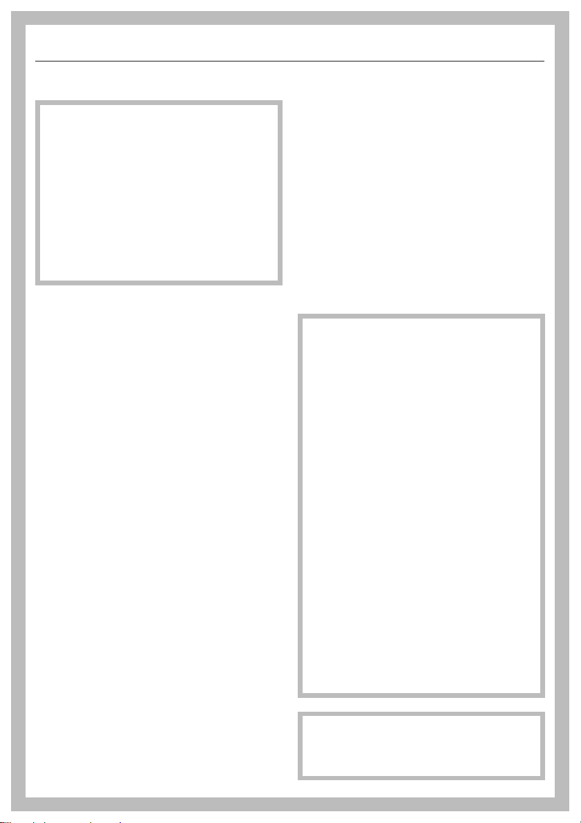
The cooktop must not be installed
~
over a dishwasher, washer, dryer,
refrigerator or freezer. Heat radiated by
the cooktop may damage the
appliances.
Install the appliance so that the
~
power cord or gas piping does not
come into contact with any portion of
the cooktop which may become hot
during use.
3
/4" (300 mm)
The power cord and a flexible gas
~
connection line must be attached in
such a way that they are not in contact
with moving parts of kitchen elements
(e.g. a drawer) and are not subject to
mechanical stress.
The safety distances listed on the
~
following pages must be carefully
maintained.
Never use a sealant unless
~
expressly stipulated. The sealing tape
of the appliance ensures adequate
sealing to the countertop.
This appliance must be installed
with its own shut off valve and the
included gas pressure regulator.
Both the valve and the regulator
must be easily accessible to the
consumer after the appliance is
installed.
This appliance must be
disconnected from the gas supply
during any pressure testing of the
system performed in excess of ½
psi (3.5 kPa). This appliance must
be isolated at test pressures equal
to or less than ½ psi (3.5 kPa).
Any pipe connections must be
made using a thread sealant
approved for gas connections.
Failure to correctly install these
items could lead to a gas leak and
subsequent explosion.
In Massachusetts installation must
be performed by a licensed
plumber/gas fitter.
26
Page 3
IMPORTANT INSTALLATION SAFETY INSTRUCTIONS
Safety distances above the
appliance
The minimum safety distance given by
the hood manufacturer must be
maintained between the cooktop and
the hood above it. See the installation
instructions of the hood for these safety
measurements.
If the hood manufacturers instructions
are not available or if flammable objects
are installed over the cooktop (e.g.
cabinets, utensil rail, etc.), a minimum
safety distance of 30" (760 mm) must
be maintained.
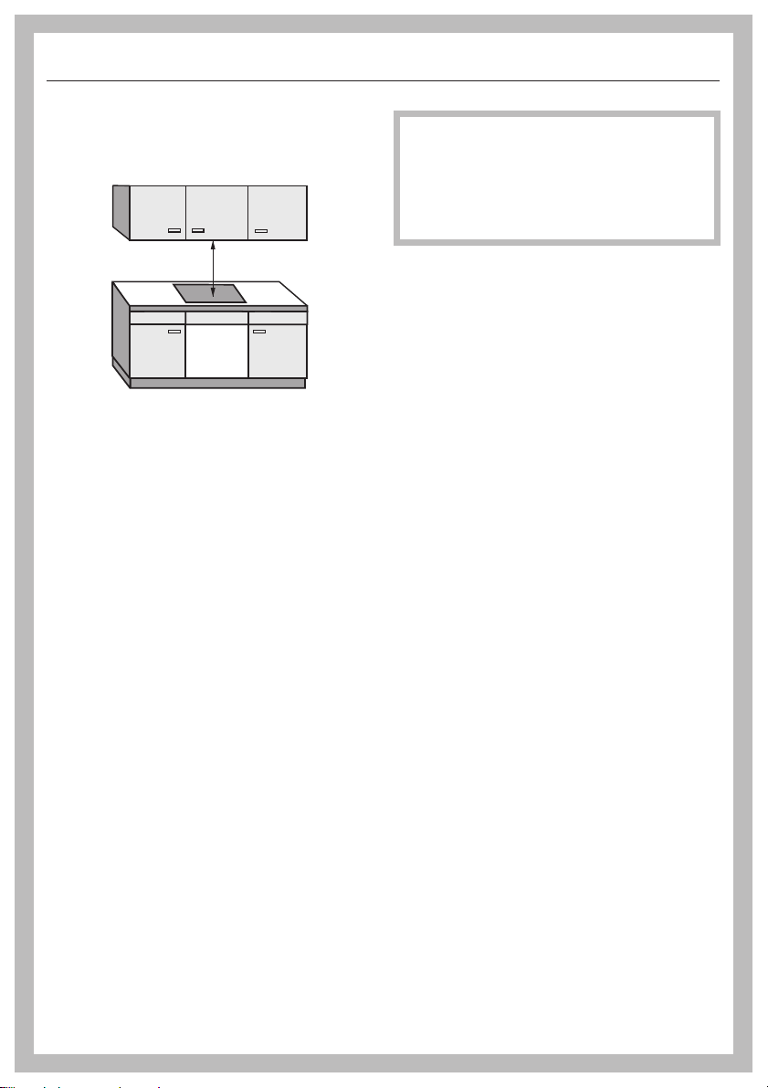
If there are several appliances
beneath a hood, and they have
different minimum safety distances
always observe the greatest
distance.
27
Page 4
IMPORTANT INSTALLATION SAFETY INSTRUCTIONS
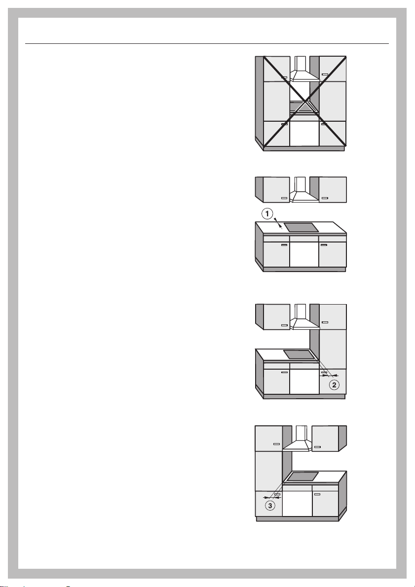
Safety distances
When installing a gas cooktop, there
may be cupboard or room walls of any
size on the rear side and on one side
(right or left) (see illustrations).
The following minimum safety distances
must be maintained:
a 2" (50 mm) minimum distance at the
rear of the countertop cutout to the
rear edge of the countertop.
b 5 7/8" (150 mm) minimum distance to
the right of the countertop cutout to
an adjacent piece of furniture (e. g.
tall cabinet) or room wall.
c 5 7/8" (150 mm) minimum distance to
the left of the countertop cutout to an
adjacent piece of furniture (e. g. tall
cabinet) or room wall.
Not allowed
Recommended
28
Not recommended
Not recommended
Page 5
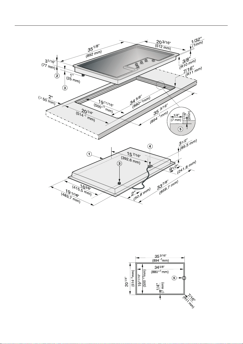
Installation dimensions
a Appliance front
b Installation height
c Gas connection
dPower supply box with connection
cable,L=4ft(1.2 m)
e Stepped cut-out for granite or marble
worktops
Please take careful note of the
detailed diagrams for the cut-out
dimensions in granite and marble
countertops.
29
Page 6
Installation
Flush mounted gas cooktops are
only suitable for installation in
granite, marble, tiled or solid wood
countertops.
If installing into a countertop made
from any other material, please
check first with the countertop
manufacturer that it is suitable for
installing a flush mounted cooktop.
This appliance requires a 36 7/16"
(900 mm) wide base unit for
installation.
The cooktop must be accessible
from below for servicing purposes
and to ensure that the seal around it
is not dislodged.
The cooktop may be installed:
in a suitable cut-out in a granite or
–
marble countertop.
in a suitable cut-out in a tiled or solid
–
wood countertop with a wooden
support frame. The frame must be
provided on site, and is not supplied
with the appliance.
30
Page 7

Installation
Granite and marble countertops
a Countertop
b Cooktop
c Gap
As the ceramic glass and the
countertop cut-out have a certain
dimensional tolerances, the size of
gap c can vary.
Make the countertop cut-out as
^
shown in "Installation dimensions".
Remember to maintain the minimum
safety distances (see "IMPORTANT
INSTALLATION SAFETY
INSTRUCTIONS").
Feed the power cord down through
^
the cut-out.
Center the cooktop b in the cut-out.
^
Connect the cooktop to the mains
^
(see "Electrical connection").
Connect the appliance to the gas
^
supply (see "Gas connection").
^ Secure the appliance at the back and
front using the brackets supplied.
See "Securing the appliance".
^ Check that the cooktop works.
^ Seal the remaining gap c with a
silicone sealant that is heat-resistant
to at least 320 °F (160 °C).
For granite and marble countertops,
only use silicone sealant that is
especially formulated for granite and
marble, and observe the sealant
manufacturer's instructions.
31
Page 8

Installation
Solid wood and tiled worktops
a Countertop
b Cooktop
c Gap
d Wooden frame 1/4" (7 mm)
(to be provided on site)
As the ceramic glass and the
countertop cut-out have a certain
dimensional tolerance, the size of
gap c can vary.
Make the countertop cut-out as
^
shown in "Building-in dimensions".
Remember to maintain the minimum
safety distances (see "IMPORTANT
INSTALLATION SAFETY
INSTRUCTIONS").
Fix the wooden frame d 1/16"
^
(2 mm) below the top edge of the
countertop (see diagram).
Feed the power cord down through
^
the cut-out.
Center the cooktop b in the cut-out.
^
Connect the cooktop to the mains
^
(see "Electrical connection").
^ Connect the appliance to the gas
supply (see "Gas connection").
^ Secure the appliance at the back and
front using the brackets supplied.
See "Securing the appliance".
^ Check that the cooktop works.
^ Seal the remaining gap c with a
silicone sealant that is heat-resistant
to at least 320 °F (160 °C).
32
Please follow the manufacturer's
instructions.
For granite and marble tiles only
use a silicone sealant that is
specifically formulated for granite
and marble, and observe the
sealant manufacturer's instructions.
Page 9

Securing the appliance
Secure the appliance as shown, using
the fixing brackets supplied.
3/4" (20 mm) countertop
1 1/4" (30 mm) countertop
After installation
Check that all the burners are operating
correctly.
The flame must not go out on the lowest
setting, or when the control is turned
quickly from a high to a low setting.
On the highest setting, the flame must
have a distinctive and visible core.
1 1/2" (40 mm) countertop
33
Page 10

Electrical connection
This appliance must be grounded
according to local or national codes.
All electrical work should be
performed by a qualified electrician
in accordance with local codes and
with the:
- National Electrical Code
ANSI / NFPA No. 70
for the USA
or
- Canadian Electrical Code Part I
for Canada
(CSA Standard C 22.1).
WARNING
,
Disconnect the appliance from the
main power supply before
installation or service. To reduce the
risk of electric shock, make sure that
the appliance is properly grounded
after installation.
Power supply
This appliance is equipped with a
three-prong grounding plug to
prevent shock hazards. It should be
plugged directly into a properly
grounded outlet. Do not cut or
remove the grounding prong from
the plug. If the plug does not fit the
outlet, have the proper outlet
installed by a licensed electrician.
To guarantee the electrical safety of
this appliance, continuity must exist
between the appliance and an
effective grounding system. It is
imperative that this basic safety
requirement be met. If there is any
doubt, have the electrical system of
the house checked by a qualified
electrician.
Note to the installer
Please leave these instructions with the
consumer or the appliance.
The automatic ignition requires that the
appliance be connected to a 120 VAC,
60 Hz power supply. The supply line
should be protected by a 15 A fuse.
Actual power consumption (during
ignition only) is 25 W.
This appliance is equipped witha4ft
(1.2 m) long power cord that is ready
for connection to the appropriate outlet.
Place the power outlet so that it is
accessible after the appliance has
been installed in the countertop.
34
Page 11

Electrical connection
Wiring diagram
,
Caution: Label all wires prior to disconnection when servicing controls.
Wiring errors can cause improper and dangerous operation.
Verify proper operation after servicing.
35
Page 12

Gas connection
Installation and service must be
performed by a qualified installer,
service agency or gas supplier.
In Massachusetts installation must
be performed by a licensed
plumber/gas fitter.
This appliance must be installed
with its own shut off valve and the
included gas pressure regulator.
Both the valve and the regulator
must be easily accessible to the
consumer to turn on or shut off the
gas supply after the appliance is
installed.
This appliance and its individual
shut off valve must be disconnected
from the gas supply during any
pressure testing of that system
performed in excess of ½ psi
(3.5 kPa). The appliance must be
isolated from the gas supply line by
closing its individual manual shut off
valve at test pressures equal to or
less than ½ psi (3.5 kPa).
The gas connection must be made
in accordance with local codes or,
in the absence of local codes, with
- the National Fuel Gas Code,
ANSI Z 21.1 / NFPA 54
for the USA
or
- the current Can / CGA B 149.1
and .2 Installation Codes for
gas
burning appliances for Canada.
Make sure that the maximum gas
supply pressure before the gas
pressure regulator is never more than
½ psi for both natural gas or LP gas.
The minimum required gas supply
pressure to get the required gas input
is
6" w.c. for natural gas
10" w.c. for LP gas.
Any pipe connections must be
made using a thread sealant
approved for gas connections.
Failure to correctly install these
items could lead to a gas leak and
subsequent explosion.
Leak testing of the appliance shall
be conducted according to the
manufacturer's instructions.
36
Page 13

Gas connection
Gas pressure regulator
A pressure regulator that is convertible
from natural to LP gas (Propane) or vice
versa is included with the appliance.
The included regulator corresponds
with the gas type of the appliance.
Verify before installing.
The adjusted pressure is:
natural gas - 4" w.c.
LP gas - 10" w.c.
a Appliance
b ½" NPT
c Regulator
For convenience, an AGA or CGA
approved flexible stainless steel gas
hose (accordion type) may be used
between the gas connection and the
regulator. This will allow the appliance
to be lifted out of the countertop for
cleaning or servicing. Make sure that
any drawers, cabinet doors, etc., do not
rub on this gas hose.
Do not use any regulator unless it
has been supplied by Miele. Doing
so may cause a gas leak.
If there is any doubt concerning
installation contact the Miele Technical
Service Department.
After connecting the appliance check
all fittings for gas leaks e.g. with
soapy water.
When installed properly, the flame will
be steady and quiet. It will also have a
sharp, blue inner core that will vary in
length proportional to the burner size.
Flame adjustment will not be
necessary.
As shown in the above diagram, the
included regulator must be used when
connecting the Miele appliance to your
gas supply. This item has been
customized by Miele to meet all
applicable safety requirements. Make
sure the regulator is easily accessible
for adjustment after the appliance has
been installed.
37
Page 14

Conversion to another type of gas
The applinace should have been
ordered for connection to either natural
gas or LP gas (propane).
If the appliance is not configured for the
proper type of gas connection please
contact your Miele Dealer.
If the appliance is to be connected to a
type of gas other than it was originally
configured for, both the regulator and
burners must be converted. A
conversion kit is available as an
optional accessory from the Miele
Technical Service Department.
38
Page 15

Burner performance
Rated load at high setting
Burner Type of gas KM 2355
BTU/hr kW
Auxiliary burner Natural gas (NG)
Liquid gas (LP)
Normal burner Natural gas (NG)
Liquid gas (LP)
High-speed
burner
Double-insert
super burner
Total Natural gas (NG)
Rated load at low setting
Burner Type of gas KM 2355
Auxiliary burner Natural gas (NG)
Normal burner Natural gas (NG)
High-speed
burner
Double-insert
super burner
Natural gas (NG)
Liquid gas (LP)
Natural gas (NG)
Liquid gas (LP)
Liquid gas (LP)
Liquid gas (LP)
Liquid gas (LP)
Natural gas (NG)
Liquid gas (LP)
Natural gas (NG)
Liquid gas (LP)
3,900
3,000
5,900
6,000
9,800
9,500
13,000
15,000
38,500
39,500
BTU/h kW
1,200
650
1,200
1,100
1,700
1,800
750
700
1.14
0.88
1.73
1.76
2.87
2.78
3.81
4.40
11.3
11.6
0.35
0.19
0.35
0.32
0.50
0.53
0.22
0.21
39
Page 16

Help protect our environment
Disposal of packing materials
The cardboard box and packing
materials are biodegradable and
recyclable. Please recycle.
Ensure that any plastic wrappings,
bags, etc. are disposed of safely and
kept out of the reach of children.
Danger of suffocation!
Disposal of an old appliance
Old appliances contain materials that
can be recycled. Please contact your
local recycling authority about the
possibility of recycling these materials.
Before discarding an old appliance
disconnect it from the electrical supply
and cut off the power cord to prevent it
from becoming a hazard.
404142
Page 17

Page 18

Page 19

43
Page 20

KM 2355
M.-Nr. 09 596 090 / 00en-US
 Loading...