

Page 1
Installation instructions
Upright Cooker
It is essential to read all instructions supplied before installing and using
the appliance for the first time. This prevents both personal injury and
damage to the appliance.
en-AU, NZ M.-Nr. 10 931 360
Page 2
Important installation information
This Upright Cooker can be used in countries other than those
specified on the appliance. It is, however, set up for connection to
the gas and electricity supplies in these countries. For trouble-free
operation of the appliance, it is best to use it in the countries
specified.
For use in other countries, please contact Miele in your country.
Risk of death from tipping!
If the Upright Cooker is not yet secured it could tip over and fatally
injure children or adults.
Secure the Upright Cooker with the anti-tip device in accordance
with the installation instructions.
The Upright Cooker must be secured and connected according to
the installation instructions.
If you have moved the Upright Cooker, slide the locking latch onto
the anti-tip device until you feel it lock into place.
Do not use the Upright Cooker if the anti-tip device has not been
properly installed and engaged.
2
Page 3

Contents
Important installation information ....................................................................... 2
Warning and Safety instructions.......................................................................... 5
Caring for the environment ................................................................................13
Features................................................................................................................ 14
Model numbers .................................................................................................... 14
Data plate ............................................................................................................. 14
Distance to the rangehood.................................................................................... 14
Items supplied with the Upright Cooker................................................................ 15
Fitting the plinth cover...................................................................................... 15
Fitting the drip tray ...........................................................................................15
Optional accessories............................................................................................. 16
RBGDF wall panel for Dual Fuel Upright Cooker .............................................16
RBS backsplash panel .....................................................................................16
Installation information....................................................................................... 17
Weight ................................................................................................................... 17
Dimensions............................................................................................................ 17
Location................................................................................................................. 18
Ventilation.............................................................................................................. 18
Required connections ........................................................................................... 18
Safety instructions for installation..................................................................... 19
Safety distances .................................................................................................. 20
Dimensional drawings for the Dual Fuel Upright Cooker ................................21
Detailed views of HR 1936 .................................................................................... 23
Detailed views of HR 1956 .................................................................................... 27
Distances from burner to the edge of the appliance ....................................... 31
Anti-tip device...................................................................................................... 33
Before installation.................................................................................................. 33
Checking the installation space ............................................................................ 34
Accessories supplied ............................................................................................ 35
Installation dimensions of locking bolt .................................................................. 36
Installing the Upright Cooker with the anti-tip device........................................... 36
Disconnecting the Upright Cooker from the anti-tip device.................................. 40
Electrical connection ..........................................................................................41
Gas connection.................................................................................................... 45
Setting the gas pressure ....................................................................................... 46
3
Page 4

Contents
Checking operation ............................................................................................... 46
Jet table................................................................................................................ 47
Natural gas ............................................................................................................ 47
Burner ratings ...................................................................................................... 48
Service.................................................................................................................. 50
Contact in case of fault ......................................................................................... 50
Data plate ............................................................................................................. 50
Warranty ................................................................................................................ 50
4
Page 5

Warning and Safety instructions
This appliance complies with all current local and national safety
requirements. However, inappropriate use can lead to personal
injury and damage to property.
Read the installation instructions carefully before installing and
connecting the Upright Cooker.
Read the operating instructions carefully before using the Upright
Cooker. The installation and operating instructions are always
jointly applicable and both contain important information on its
installation, safety, use and maintenance. This prevents both
personal injury and damage to the appliance.
Miele cannot be held liable for damage caused by non-compliance
with these instructions.
Keep the installation instructions and the operating instructions in
a safe place and pass them both on to any future owner.
5
Page 6

Warning and Safety instructions
Correct application
This Upright Cooker is designed for domestic use and for use in
similar environments.
The appliance is not intended for outdoor use.
The Upright Cooker is exclusively intended for use under normal
domestic conditions:
– Use the oven for baking, roasting, grilling, cooking, defrosting and
drying food.
– Use the cooktop to cook food and keep it warm.
All other types of use are not permitted.
This Upright Cooker is not intended for use by people (including
children) with reduced physical, sensory or mental capabilities or
lack of experience and knowledge, unless they have been given
supervision and instruction concerning its use by a person
responsible for their safety.
They may only use the appliance unsupervised if they have been
shown how to use it in a safe way. They must be able to recognise
and understand the dangers of misuse.
This Upright Cooker is supplied with a special lamp to cope with
particular conditions (e.g. temperature, moisture, chemical
resistance, abrasion resistance and vibration). This special lamp
must only be used for the purpose for which it is intended. It is not
suitable for room lighting.
6
Page 7

Warning and Safety instructions
Safety with children
Young children must not be allowed to use this appliance.
Children should be supervised in the vicinity of the Upright
Cooker. Do not allow them to play with the appliance.
Danger of burning from incorrect operation! Do not allow children
to operate the Upright Cooker.
Danger of suffocation! Whilst playing, children may become
entangled in packaging material (such as plastic wrapping) or pull it
over their head with the risk of suffocation. Keep packaging material
away from children.
Danger of burning!
Do not store anything which might arouse a child's interest in
storage areas above the Upright Cooker. Otherwise children could
be tempted to climb onto the Upright Cooker with the risk of burning
themselves.
Danger of injury! The maximum load capacity of the door is 8kg
for the Speed Oven and 15kg for the Oven. Children can hurt
themselves on an open door.
Ensure that children do not sit on or swing on the door.
7
Page 8

Warning and Safety instructions
Technical safety
Unauthorised installation, maintenance and repairs can cause
considerable danger for the user. Installation, maintenance and
repairs must only be carried out by a Miele authorised technician.
Do not lift or carry the Upright Cooker by the oven door handle or
control panel.
Check whether the anti-tip device is properly installed and locked
into place (see “Anti-tip device”):
– The anti-tip device must be fastened to the floor or wall with
suitable screws.
– The locking latch must be noticeably engaged with the bolt on the
anti-tip device.
Slide the Upright Cooker's locking latch into place on the anti-tip
device. The locking latch must be noticeably engaged with the bolt
on the anti-tip device.
Damage to the Upright Cooker can compromise your safety.
Check the appliance for visible signs of damage. Never use a
damaged Upright Cooker.
Reliable and safe operation of the Upright Cooker can only be
guaranteed if it is connected to the mains electricity supply.
The electrical safety of this appliance can only be guaranteed
when continuity is complete between it and an effective earthing
system. It is essential that this basic safety requirement is present
and tested regularly. If in doubt, consult a suitably qualified
electrician.
The connection to the gas supply must be carried out by a
suitably qualified and competent person in accordance with current
local and national safety regulations. If the plug is removed from the
connection cable or if the cable is supplied without a plug, the
Upright Cooker must be connected to the electricity supply by a
suitably qualified electrician.
8
Page 9

Warning and Safety instructions
Before connecting the Upright Cooker to the mains supply, ensure
that the connection data on the data plate (voltage and frequency)
match the mains electricity supply.
Compare this data before connecting the appliance to the mains. If
in doubt, consult a qualified electrician.
If the mains connection cable is damaged, it must only be
replaced by a Miele approved service technician in order to avoid a
hazard.
During installation, maintenance and repair work, e.g. if the oven
lighting is faulty, the Upright Cooker must be completely
disconnected from the household electricity supply (see “Problem
solving guide”). The gas inlet valve must be closed. To ensure this:
– Switch off the mains circuit breaker, or
– Remove the screw-out fuse (in countries where this is applicable),
or
– Switch off at the wall socket and withdraw the plug. Do not pull
on the cable, but pull the plug to do this.
– Close the gas inlet valve.
Multi-socket adapters and extension leads do not guarantee the
required safety of the appliance (fire hazard). Do not use these to
connect the Upright Cooker to the mains electricity supply.
Any contact with live connections or tampering with the electrical
or mechanical components of the Upright Cooker will endanger your
safety and may lead to appliance malfunctions.
Do not open the Upright Cooker housing under any circumstances.
This Upright Cooker must not be installed and operated in mobile
installations (e.g. on a ship).
While the Upright Cooker is under warranty, repairs should only
be undertaken by a Miele authorised service technician. Otherwise
the warranty is invalidated.
9
Page 10

Warning and Safety instructions
Faulty components must only be replaced by genuine Miele spare
parts. The manufacturer can only guarantee the safety of the
appliance when Miele replacement parts are used.
The Upright Cooker requires a sufficient supply of cool air for
efficient operation. Make sure that the supply of cool air is not
hindered in any way. Furthermore the required supply of cool air
must not be excessively heated by other heat sources (e.g. solid fuel
stoves).
If the Upright Cooker is to be built in behind a furniture front (e.g. a
door) do not close the door while the Upright Cooker is in use. Heat
and moisture can build up behind the closed door. This can result in
damage to the Upright Cooker, surrounding cupboards and the floor.
Leave the furniture door open until the Upright Cooker has cooled
down completely.
In areas which may be subject to infestation by cockroaches or
other vermin, pay particular attention to keeping the appliance and
its surroundings clean at all times. Any damage caused by
cockroaches or other vermin will not be covered by the warranty.
DO NOT MODIFY THIS APPLIANCE.
This cooktop is not suitable for installation and operation with
aftermarket lids or covers fitted.
10
Page 11

Warning and Safety instructions
Cleaning and care
The steam from a steam cleaning appliance could reach electrical
components and cause a short circuit.
Do not use a steam cleaner to clean the Upright Cooker.
Scratches on the door glass can result in the glass breaking.
Do not use abrasive cleaners, hard sponges, brushes or sharp metal
tools to clean the door glass.
The shelf runners can be removed for cleaning (see “Cleaning and
care”).
Ensure that they are replaced correctly and do not use the oven
without them fitted.
Coarse soiling should be removed before running the Pyrolytic
cleaning programme. If not removed, coarse soiling can smoke and
cause the Pyrolytic cleaning programme to switch itself off.
Stainless steel appliances
The coated stainless steel surface can be damaged by adhesives
and will lose its dirt-repelling properties. Do not adhere sticky notes,
transparent tape, masking tape or other adhesives onto the stainless
steel surface.
The surface is susceptible to scratching. Even magnets can cause
scratches.
11
Page 12

Warning and Safety instructions
Accessories
Use only genuine original Miele spare parts. If spare parts or
accessories from other manufacturers are used, the warranty will be
invalidated, and Miele cannot accept liability.
Only use the Miele food probe supplied with this oven. If it is
faulty, it must only be replaced with a suitable original Miele food
probe.
The plastic on the food probe can melt at very high temperatures.
Do not use the food probe when grilling (exception: Fan Grill). If
you are not using the food probe, do not store it in the oven.
The high temperatures used during the Pyrolytic cleaning
programme will damage accessories that are not designed for
cleaning in the Pyrolytic programme. Please remove these
accessories from the oven interior before starting the Pyrolytic
cleaning programme. This also applies to non-pyrolytic accessories
purchased separately to the oven (see “Cleaning and care”).
12
Page 13
Caring for the environment
Disposal of the packing material
The transport and protective packaging
has been selected from materials which
are environmentally friendly for
disposal, and can normally be recycled.
Recycling the packaging reduces the
use of raw materials in the
manufacturing process and also
reduces the amount of waste in landfill
sites. Ensure that any plastic
wrappings, bags etc. are disposed of
safely and kept out of the reach of
babies and young children. Danger of
suffocation.
Disposing of your old appliance
Electrical and electronic appliances
often contain valuable materials. They
also contain specific materials,
compounds and components, which
were essential for their correct function
and safety. These could be hazardous
to human health and to the environment
if disposed of with your domestic waste
or if handled incorrectly. Please do not,
therefore, dispose of your old appliance
with your household waste.
Please dispose of it at your local
community waste collection / recycling
centre for electrical and electronic
appliances. You are also responsible for
deleting any personal data that may be
stored on the appliance prior to
disposal. Please ensure that your old
appliance poses no risk to children
while being stored prior to disposal.
13
Page 14

Features
Model numbers
A list of the model numbers described
in these operating instructions can be
found on the back page.
Data plate
The data plate is located behind the
plinth cover. The plinth cover is
attached to the plinth of the Upright
Cooker by magnets so it can be
removed and re-attached easily.
The data plate states the model number
of your Upright Cooker, the serial
number as well as the connection data
(voltage, frequency and maximum rated
load).
Have this information available if you
need to contact Miele so that any
issues can be rectified as quickly as
possible.
Distance to the rangehood
The safety distance specified by the
manufacturer of the rangehood must be
maintained between the cooktop and
the rangehood above it.
If the rangehood manufacturer's
instructions are not available or if
flammable objects are installed above
the appliance (e.g. cabinets, utensils rail
etc.), a minimum safety distance of
760mm must be maintained.
If there is more than one appliance
installed below the rangehood, each
with a different safety clearance, the
largest required clearance must be
adhered to.
14
Page 15
Features
Items supplied with the Upright Cooker
Items supplied will vary depending on
model:
– Installation instructions for the
Upright Cooker
– Operating instructions for the Dual
Fuel Upright Cooker 36"
(Oven)
– Operating instructions for the Dual
Fuel Upright Cooker 48"
(Oven)
– Operating instructions and recipe
booklet for the Dual Fuel Upright
Cooker 48"
(Speed oven)
– Operating instructions for the Dual
Fuel Upright Cooker 48"
(Gourmet warming drawer)
– Operating instructions for the Dual
Fuel Upright Cooker
(Gas cooktop)
– Anti-tip device including screws for
securing the Upright Cooker
Plinth cover and drip tray
Components for the 36" Upright
Cooker are located in the packaging
of the Upright Cooker.
Components for the 48" Upright
Cooker are pre-fitted.
Fitting the plinth cover
The plinth cover has sheet metal tabs
and magnets by means of which it can
be positioned and attached to the
base of the Upright Cooker.
Position the plinth cover in such a
way that the sheet metal tabs are
facing the holes provided in the base.
Push the plinth cover onto the base
of the Upright Cooker until it clicks
into place.
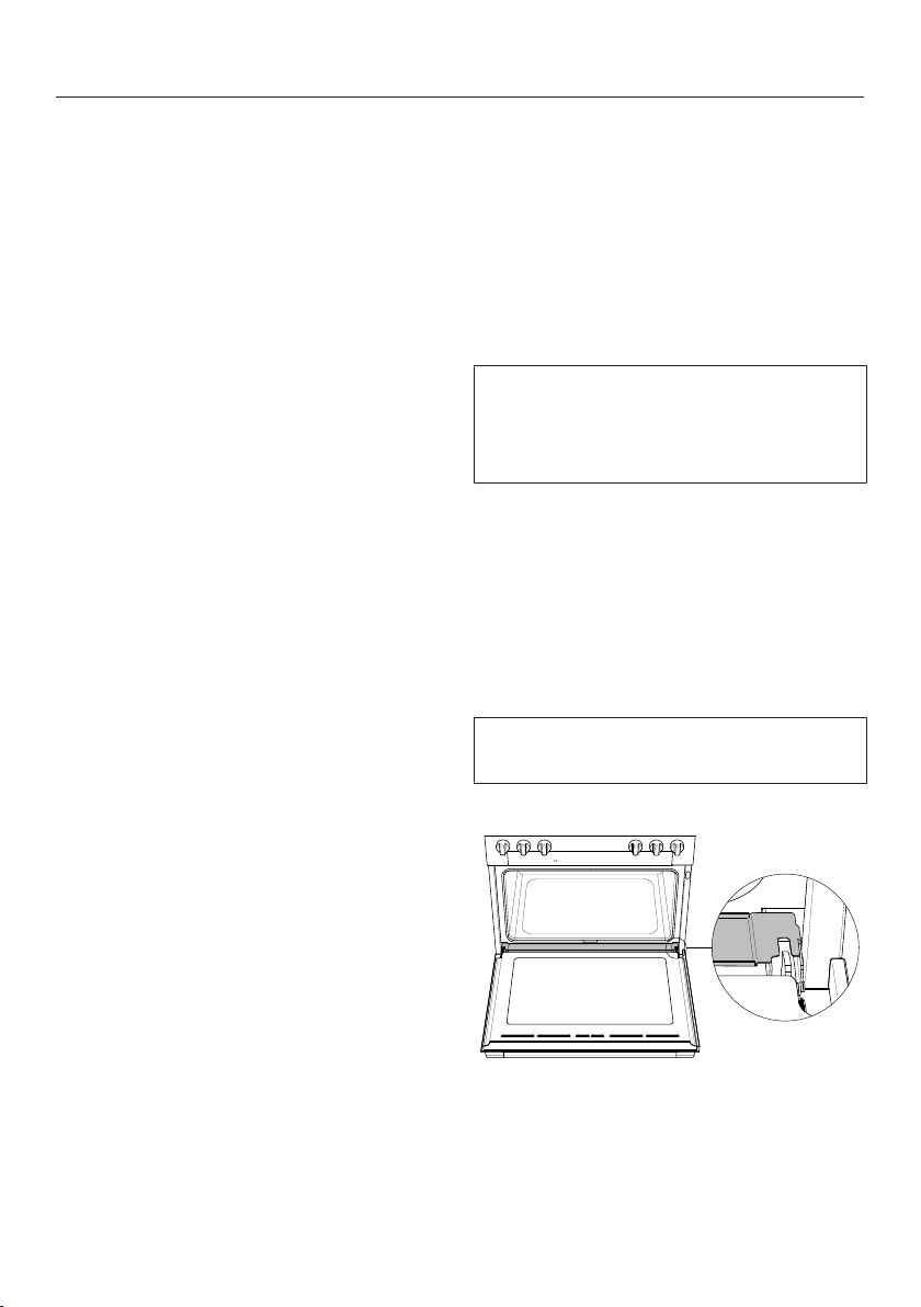
Fitting the drip tray
The drip tray covers the gap between
the oven cavity and the door.
Open the oven door.
– Various accessories
Place the drip tray over the gap
between the oven cavity and the
door.
Close the oven door.
15
Page 16

Features
Optional accessories
All accessories listed in these
instructions are designed to be used
with the Miele Upright Cooker.
These are available to order via the
Miele online shop or directly from Miele
(see the end of this booklet for contact
details).
When ordering, please quote the model
number of your Upright Cooker and the
reference number of the accessories
required.
RBGDF wall panel for Dual Fuel Upright Cooker
Depending on the model, you can
exchange the existing edge profile on
your appliance for a taller wall panel.
The wall panel is available in the
following heights: 305 mm and 508 mm.
If installing the Upright Cooker against a
wall made of flammable materials, a
wall panel that is at least 305mm high
must be fitted. If you do not wish to
replace the existing edge profile, the
Upright Cooker must be installed with a
gap of at least 305mm between it and
the wall made of flammable materials.
Fitting the RBGDF wall panel
The back of the Upright Cooker must
be accessible.
Fit the wall panel before installing the
anti-tip device and connecting the
Upright Cooker.
Loosen the screws of the edge
profile.
Pull back the edge profile slightly until
it can be removed.
Refit the wall panel in the reverse order.
RBS backsplash panel
The backsplash panel is designed for
installation with a Miele rangehood.
Please observe the installation
instructions supplied with the
rangehood.
16
Page 17

Installation information
Do not lift or carry the Upright Cooker by the oven door handle or the control
panel.
The Upright Cooker is heavy.
Due to the size and weight of the appliance, installation should be performed by
two people.
Weight
Model Gross weight Net weight *
HR 1936 Approx. 205kg Approx. 175kg
HR 1956 Approx. 295kg Approx. 250kg
* including accessories: shelf runners, 1rack, 1tray
Dimensions
Model Width Height Depth
HR 1936 915mm 902 - 940mm 698mm
HR 1956 1220mm 902 - 940mm 698mm
17
Page 18

Installation information
Location
This Upright Cooker is not intended for outdoor use.
To ensure the safe installation of the appliance and to guarantee its correct
functioning, the floor of the niche where the appliance is to be installed must be
smooth and even.
The niche floor must be made of strong, rigid material.
Because the Upright Cooker is heavy and has to be secured with the anti-tip
device supplied, the surface must be able to bear the full load of the appliance. If
necessary, seek the advice of an architect or construction expert. The Upright
Cooker must not be installed on a base.
Ventilation
The air intake and outlet openings must not be covered or blocked in any way.
Required connections
Model Electrical connection Gas connection
HR 1936 Required Required
HR 1956 Required Required
18
Page 19

Safety instructions for installation
A gas cooktop must not be installed directly next to a deep fat
fryer as the gas flames could ignite the fat in the fryer. It is essential
to maintain a distance of at least 300mm between these two
appliances.
The electrical cable and any flexible gas connection pipes must be
installed in such a way so that they do not come into contact with
any moving kitchen parts (e.g. a drawer) after the Upright Cooker
has been installed, and that they cannot be subjected to any
mechanical action which could cause damage.
The appliance must be installed in accordance with AS/NZS 5601
and relevant local and national regulations.
Remove any protective wrapping and stickers before installation
(except the data plate).
Carefully observe the safety clearances listed on the following
pages.
All dimensions in this instruction booklet are given in mm.
19
Page 20

Safety distances
A gas appliance shall be installed such
that the surface temperature of any
nearby combustible surface* will not
exceed 65°C above ambient.
The minimum clearance from a
combustible surface shall be a 200mm
horizontal distance from the periphery
of any gas burner (AS/NZS 5601.1).
If that horizontal clearance is less than
200mm, that vertical surface must be
protected by a non-combustible
material for 150mm above the cooktop
surface across the entire length (depth,
width).
The shown area indicates the protected
surface, which may be ceramic tiles or
other approved material.
* Combustible surface: A material
which will ignite and burn, and
includes material which has been
flameproofed.
20
Page 21

Dimensional drawings for the Dual Fuel Upright Cooker
The shaded area represents the installation area for service connections:
E = Electrical connection, G = Gas connection
Position Dimensions Description
902 - 940mm Distance from the floor to cooktop surface
254mm Minimum distance to flammable surfaces
21
Page 22

Dimensional drawings for the Dual Fuel Upright Cooker
HR 1936
When two or more appliances which have different safety distances are
installed together below a rangehood, the greatest safety distance required
must be observed.
Position Dimensions Description
914 mm Niche width
760 mm Required safety distance if flammable objects are
installed above the appliance (e.g. cabinets,
utensils rail etc.).
The safety distance specified by the manufacturer of the rangehood
must be maintained between the cooktop and the rangehood above
it.
340 mm Maximum width/projection of overhead cupboards
HR 1956
When two or more appliances which have different safety distances are
installed together below a rangehood, the greatest safety distance required
must be observed.
Position Dimensions Description
1220 mm Niche width
760 mm Required safety distance if flammable objects are
installed above the appliance (e.g. cabinets,
utensils rail etc.).
The safety distance specified by the manufacturer of the rangehood
must be maintained between the cooktop and the rangehood above
it.
340 mm Maximum width/projection of overhead cupboards
22
Page 23

Dimensional drawings for the Dual Fuel Upright Cooker
Detailed views of HR 1936
Side view of HR 1936
(x) = depends on the appliance height adjustment: 127 mm - 165.1 mm
23
Page 24

Dimensional drawings for the Dual Fuel Upright Cooker
Detailed side view of HR 1936
24
Page 25

Dimensional drawings for the Dual Fuel Upright Cooker
Front view of HR 1936
(x) = depends on the appliance height adjustment: 127 mm - 165.1 mm
25
Page 26

Dimensional drawings for the Dual Fuel Upright Cooker
126.3 mm
778.5 mm
94.5 mm
696 mm
Rear view of HR 1936
E = Electrical connection
G = Gas connection
26
Page 27

Dimensional drawings for the Dual Fuel Upright Cooker
Detailed views of HR 1956
Side view of HR 1956
(x) = depends on the appliance height adjustment: 101.6 mm - 139.7 mm
27
Page 28

Dimensional drawings for the Dual Fuel Upright Cooker
Detailed front view of HR 1956
28
Page 29

Dimensional drawings for the Dual Fuel Upright Cooker
Front view of HR 1956
(x) = depends on the appliance height adjustment: 101.6 mm - 139.7 mm
29
Page 30

Dimensional drawings for the Dual Fuel Upright Cooker
1028 mm
126.3 mm
805 mm
96 mm
Rear view of HR 1956
E = Electrical connection
G = Gas connection
30
Page 31

Distances from burner to the edge of the appliance
HR 1936
31
Page 32

Distances from burner to the edge of the appliance
HR 1956
32
Page 33

Anti-tip device
Before installation
WARNING
Children and adults can tip over the
Upright Cooker if it has not been
secured. This may lead to fatal
injuries.
Make sure that the anti-tip device is
properly installed and locked into
place. It should be screwed to the
floor or wall and locked in the centre
of the base of the Upright Cooker.
You must take care to protect the
flooring when moving the Upright
Cooker.
After moving the Upright Cooker,
make sure that the anti-tip device
locks back into place. It should be
screwed to the floor or wall and
locked in the centre of the base of
the Upright Cooker.
Do not use the Upright Cooker if the
anti-tip device has not been properly
installed and engaged.
Due to the size and weight of the
appliance, installation should be
performed by two people.
Do not lift or carry the Upright
Cooker by the oven door handle or
the control panel.
The anti-tip device is also used as a
restraining device if the appliance is
connected to the gas supply using a
hose assembly. Take care when
moving the Upright Cooker to ensure
that the hose is not subject to
tension, abrasion, kinking or
permanent deformation.
Any apertures behind the appliance
or in the floor underneath the
appliance must be sealed.
It is a good idea to remove the door
(see “Removing the door”) and the
accessories before installing the
appliance. This will make it easier to
install the Upright Cooker in its niche.
Once the Upright Cooker has been
installed and secured against tipping,
you can reattach the oven door (see
“Refitting the door”).
33
Page 34

Anti-tip device
A
Checking the installation space
Install the anti-tip device on a base capable of bearing significant weight, such as
a concrete floor, concrete wall or timber framing. The surface must be flat and
level.
If the rear of the Upright Cooker has a distance A to the supporting wall due to
unevenness or the wall covering (e.g. tile level), you must install the anti-tip
device on the supporting floor. Alternatively, you can install the anti-tip device
with an adapter between the supporting wall and the anti-tip device. The
adapter must compensate for distance A and be made of suitable material so
that a supporting connection is made between the wall and anti-tip device. Use
appropriate screws (length and diameter).
A = Distance between the rear of the Upright Cooker and the supporting wall
Check the floor surface.
Check the installation dimensions.
34
Page 35

Anti-tip device
Check the building drawings for supply cables and pipework. Make sure that
you do not damage any cables or pipes when drilling holes to attach the anti-tip
device.
Check the position of the electric, gas and plumbing connections (see “Electrical
connection,” “Gas connection” and “Plumbing”). An overview of electrical and
gas connections required for your Upright Cooker can be found in “Installation
information”.
Accessories supplied
– 1 anti-tip device
– 4 screws
– 4 plugs
35
Page 36

Anti-tip device
X
Installation dimensions of locking bolt
Anti-tip device, front view
Model Width X
HR 1936 915mm 97mm
HR 1956 1220mm 82mm
Installing the Upright Cooker with the anti-tip device
Wear safety shoes and gloves.
The anti-tip device should be installed
at the back of the Upright Cooker, half
way along the bottom edge.
Measure the installation space for the
Upright Cooker close to floor level.
Mark the wall at the middle of the
space width.
Position the notch of the anti-tip
device on the wall marking.
The anti-tip device must fit tightly on
the floor or the wall.
36
Page 37

1
3
2
Fixing to the floor
1
2
3
Anti-tip device
Screw the locking nut to the bolt,
see the “Installation dimensions of
locking bolt” table.
Attaching to the wall
a
Anti-tip device
b
Screws
c
Locking nut
Secure the anti-tip device with four
screws to a surface with suitable
load bearing capacity, either to the
floor or the wall.
37
Page 38

Anti-tip device
Do not push the Upright Cooker
into position until all supply
connections have been
established.
The plinth cover is attached to the
base of the Upright Cooker by
magnets.
Complete all necessary connections
for the Upright Cooker. Read the
information in the “Electrical
connection” and “Gas connection”
sections.
The Upright Cooker can be damaged
if it is lifted by the control panel, the
island trim or the door handle.
Open the oven door and hold the
appliance by the front of the oven
cavity.
Lift the front of the Upright Cooker
and move it with the help of the rear
wheels.
Slide the Upright Cooker into
position, guiding the middle of the
appliance onto the anti-tip device.
Slide the appliance all the way back
to the wall.
a
Plinth cover
b
Locking latch
Remove the plinth cover from the
Upright Cooker.
Pull out the locking latch .
The locking latch fits into the base
plate of the Upright Cooker. It can be
pulled out and pushed back in again.
Its length is approximately equal to the
depth of the Upright Cooker.
A slot is located in the non-visible rear
section of the locking latch. This slot
engages with the bolt of the anti-tip
device when you slide the locking
latch back in.
38
Page 39

Anti-tip device
The Upright Cooker can be aligned if
necessary. Check it with a spirit level.
– Rear adjustment right and left:
You will need an SW 10 spanner.
– Front adjustment right and left:
You will need an SW 16 spanner
for the locknut and an SW 13
spanner for the adjustable nut.
In the Upright Cooker housing, there is
an opening for the bolt of the antitip device. The opening allows the
Upright Cooker to be pushed onto the
anti-tip device and back to the wall.
The locking latch must noticeably
engage with the bolt so that anti-tip
protection is ensured for the Upright
Cooker.
a
Locking latch
b
Rear adjustment
c
Front adjustment
Align the Upright Cooker.
Slide the locking latch firmly back.
a
Opening in the Upright Cooker
housing
b
Anti-tip device bolt
c
Locking latch with slot
The plinth cover can only be attached
if the locking latch has been
pushed all the way into the appliance.
Secure the plinth cover to the Upright
Cooker.
39
Page 40

Anti-tip device
Disconnecting the Upright Cooker from the anti-tip device
WARNING
Children and adults can tip over the
Upright Cooker if it has not been
secured. This may lead to fatal
injuries.
If you need to remove the Upright
Cooker from its installation space, e.g.
for service, you first need to
disconnect it from the anti-tip device.
Follow the instructions for installation
in reverse order.
40
Page 41

Electrical connection
Danger of injury!
Installation, maintenance and repairs
by unqualified persons could be
dangerous. Miele cannot be held
liable for unauthorised work.
All electrical work must be
undertaken by a suitably qualified
and competent person in strict
accordance with current national and
local safety and building code
regulations.
Connection of this appliance must
comply with national and local safety
regulations.
A suitable means of disconnection must
be provided on site for each pole.
Suitable means of disconnection
include switches with an all-pole
contact gap of at least 3mm. These
include isolator switches, fuses and
relays.
A means of disconnection must be
incorporated in the fixed wiring in
accordance with the wiring rules.
For extra safety, it is advisable to
protect the appliance with a suitable
residual current device (RCD) with a trip
current of 30 mA.
Connection data
The connection data is quoted on the
data plate. The data plate of the Upright
Cooker is located behind the removable
plinth cover (see “Overview Upright
Cooker”).
Please ensure the connection data
matches the household supply.
When replacing or changing the
mains connection cable, ensure that
the correct cable type is used.
For a 3 phase connection use cable
type H05 VV-F.
For a 1 phase connection use cable
type S05 VV-F.
NEW ZEALAND
If this Upright Cooker is to be
connected to a new or upgraded
electrical installation, it must be
connected to the mains electricity
supply by a supply cord fitted with:
– an appropriately rated plug that is
compatible with the socket fitted to
the final sub-circuit in the fixed wiring
that supplies this cooking range; or
– an appropriately rated installation
male connector that is compatible
with the installation female connector
fitted to the final sub-circuit in the
fixed wiring that supplies this
appliance.
41
Page 42

Electrical connection
Upright Cooker
Maximum rated load: see data plate.
HR 1936
Under adverse conditions of the power
supply network this device can cause
irritating voltage fluctuations. If the
network impedance at the point of
coupling to the public supply network is
higher than 0.45Ω, additional measures
may be required to assure normal use
of the appliance. Information about the
impedance can be inquired at the local
distribution network operator, if
necessary.
Wiring diagram
42
Page 43

NEW ZEALAND:
The size of the supply cord to be used is as follows:
Electrical connection
Type 3 phase electrical
connection
HR 1936
HR 1956
2.5mm
2.5mm
2
2
1 phase electrical
connection
4.0mm
10.0mm
2
2
43
Page 44

Electrical connection
4
5
1
6
7
6
7
8
5
2
3
1
5
6
2
3
4
7
HR 1956: Electrical conversion
The electrical connection can be
converted.
The ferrite ring must be used with both
the three phase and single phase
supplies in accordance with the
diagrams below.
Three phase 3 N AC 230 V
a
1 x ferrite ring
b
2 x bridges
c
PE (green/yellow)
d
3 x bridges
e
N (blue)
f
L 3 (grey)
g
L 2 (black)
h
L 1 (brown)
Single phase AC 230 V
a
1 x ferrite ring
b
PE (green/yellow)
c
N (blue)
d
L (black or brown)
e
2 x bridges
f
1 x bridge
g
2 x bridges
44
Page 45

Gas connection
Connection to the gas supply
should only be undertaken by an
approved and registered gas
installer. The installer is responsible
for ensuring that the appliance
functions correctly when installed.
The gas connection must be
installed so that connection can be
made either from inside or outside
the kitchen furniture unit. The
isolating valve must be easily
accessible and visible (by opening
the cabinet door if necessary).
Check with your local gas supplier
about the type of gas and compare
this information with the type of gas
quoted on the appliance's data plate.
The cooktop is not connected to an
exhaust duct.
When installing and connecting the
appliance please observe all relevant
installation instructions and ensure it
has adequate ventilation once
installed.
Gas connections, pipes and
connection cables can be damaged
if exposed to heat from the cooktop.
After installation make sure that
neither the gas pipe nor the mains
cable can come into contact with hot
parts of the appliance and that the
gas pipe and connections on the
cooktop cannot come into contact
with hot exhaust fumes.
Flexible gas pipes can be damaged
when installed incorrectly.
Ensure that the hose assembly is not
exposed to high temperatures
exceeding the maximum temperature
specified by the manufacturer, and
that it is not subjected to strain,
kinking, permanent deformation or
damage by vermin.
The gas pressure must be set by an
approved gas fitter and a full
operational test and a test for
possible leakages must be carried
out by the gas fitter after installation.
Connection to the gas supply must
be carried out in strict accordance
with local and national safety
regulations (e.g AS/NZS5601). Every
appliance should have its own easily
accessible isolating valve and test
point.
Any special local conditions relating
to gas installations as well as
building regulations must also be
observed.
45
Page 46

Gas connection
a
The gas connection is set up for natural
gas (see label on the appliance).
Connection to the appliance
The gas connection has a ¹/₂" conical
thread. There are two possibilities for
connection:
– fixed connection
– flexible hose class B or D which
complies with AS/NZS 1869 and
must be certified. The minimum
innerØ must be 10mm and the
maximum length 1.2m.
Setting the gas pressure
The gas pressure must be set by the
approved gas fitter as shown on the
data plate:
Natural gas 1.0 kPa
After installation, the test must be
carried out by an approved gas fitter
to confirm the correct gas pressure.
The gas pressure must be set with all
of the burners operating at maximum
setting.
The gas regulator is only included with
appliances which are set up for
connection to natural gas.
a
Pressure Test Point
Loosen the screw in the test point
until it is free in its housing. The
screw is retained in this position.
Connect the hose from the pressure
gauge.
Light all of the burners.
Test and ensure that the gas pressure
at the test point is 1.0 kPa.
Disconnect gauge and screw in the
test point screw.
Checking operation
Check all gas fittings for leaks.
Ignite all burners to check that they
are operating correctly.
– The flame must not go out on the
lowest setting, or when the control is
turned quickly from the highest to the
lowest setting.
– On the highest setting, the flame
must have a distinctive and visible
core.
46
Page 47

Natural gas
Jet table
Main jet Simmer jet Adjustment jet Adjustment jet
Code Code Code Code
Semi-rapid
burner
Rapid burner 146 1.46 80 0.80 88 0.88 60 0.60
Ultra-rapid
burner
Teppan Yaki
plate
119 1.19 64 0.64 75 0.75 55 0.55
175 1.75 84 0.84 90 0.90 68 0.68
155 1.55 – – – – – –
47
Page 48

Burner ratings
Nominal ratings HR 1936
Natural gas, 1.0 kPa
Burner Gas type Highest setting Lowest setting
MJ/h MJ/h
Semi-rapid burner Natural gas 8.75 1.10
Rapid burner Natural gas 14.00 1.35
Ultra-rapid burner Natural gas 17.00 2.20
Teppan Yaki plate
burner
Total Natural gas 60.50
Natural gas 12.00 –
48
Page 49

Burner ratings
Nominal ratings HR 1956
Natural gas, 1.0 kPa
Burner Gas type Highest setting Lowest setting
MJ/h MJ/h
Semi-rapid burner Natural gas 8.70 1.10
Rapid burner Natural gas 14.00 1.35
Ultra-rapid burner Natural gas 17.00 2.20
Teppan Yaki plate
burner
Total Natural gas 77.80
Natural gas 12.00 –
49
Page 50

Service
Contact in case of fault
In the event of any faults which you
cannot remedy yourself, please contact
Miele.
Contact information for Miele can be
found at the end of this booklet.
Please quote the model and serial
number of your appliance when
contacting Miele. This information can
be found on the data plate.
Data plate
The data plate is located behind the
plinth cover. The plinth cover is
attached to the plinth of the Upright
Cooker by magnets so it can be
removed and re-attached easily.
The data plate states the model number
of your Upright Cooker, the serial
number as well as the connection data
(voltage, frequency and maximum rated
load).
Have this information available if you
need to contact Miele so that any
issues can be rectified as quickly as
possible.
Warranty
The manufacturer's warranty for this
appliance is 2years.
For further information, please refer to
your warranty booklet.
50
Page 51

www.miele.com.au
Miele Experience Centre and
Head Office Melbourne:
1 Gilbert Park Drive
Knoxfield, VIC 3180
Miele Experience Centre South Melbourne:
206-210 Coventry Street
South Melbourne, VIC 3205
Miele Experience Centre and Office Sydney:
3 Skyline Place
Frenchs Forest, NSW 2086
Miele Experience Centre and Office Brisbane:
Tenancy 4C, 63 Skyring Terrace
Newstead, QLD 4006
Miele Experience Centre and Office Perth:
83-85 Sir Donald Bradman Drive
Hilton, SA 5033
205-207 Stirling Highway
Claremont, WA 6010
Miele Experience Centre and Office Adelaide:
Miele Australia Pty. Ltd.
Miele New Zealand Limited
Level 2, 10 College Hill
Freemans Bay, Auckland 1011
Miele Experience Centre
Auckland:
8 College Hill
Freemans Bay, Auckland 1011
Telephone:
0800 464 353 (0800 4 MIELE)
www.miele.co.nz
Miele Global Headquarters
Germany
Miele & Cie. KG
Carl-Miele-Straße 29
33332 Gütersloh
Federal Republic of Germany
Head Office:
IRD 98 463 631
ACN 005 635 398
ABN 96 005 635 398
Miele Experience Centre Gold Coast:
131 Ferry Road
Southport, QLD 4215
Page 52

HR1936; HR1956
M.-Nr. 10 931 360 / 03en-AU, NZ
 Loading...