

MIELE HR 1956-2 G, HR 1955-2 G, HR 1134-1 LP, HR 1936-2 LP, HR 1936-2 G Installation guide
...Page 1
Installation Instructions
30" Electric, 30" Induction Range
30", 36" All Gas Range
30", 36", 48" Dual Fuel Range
To prevent accidents and damage to the range, you
instructions supplied before installing or using the appliance.
en-US, CA M.-Nr. 11 060 790
must
read all
Page 2
PRECAUTIONS TO AVOID POSSIBLE EXPOSURE TO
EXCESSIVE MICROWAVE ENERGY
PRECAUTIONS TO AVOID POSSIBLE EXPOSURE TO EXCESSIVE
MICROWAVE ENERGY
(a) Do not attempt to operate this oven with the door open since
open-door operation can result in harmful exposure to microwave
energy. It is important not to defeat or tamper with the safety
interlocks.
(b) Do not place any object between the oven front and the door or
allow soil or cleaner residue to accumulate on sealing surfaces.
(c) Do not operate the oven if it is damaged. It is particularly
important that the oven door closes properly and that there is no
damage to the: (1) door (bent), (2) hinges and latches (broken or
loosened), (3) door seals and sealing surfaces.
(d) The oven should not be adjusted or repaired by anyone except
properly qualified service personnel.
2
Page 3
IMPORTANT SAFETY INSTRUCTIONS
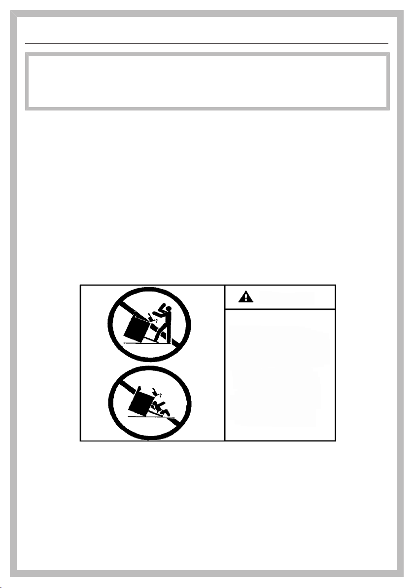
All ranges can tip
Injury to persons
could result
Install anti-tip devices
packed with range
See installation
instructions
WARNING
WARNING
Children and adults can tip over the range if has not been secured.
This may lead to fatal injuries.
This range must be secured and connected using the anti-tip
device according to the installation instructions.
If you have moved the range, slide the locking latch onto the anti-
tip device until you feel it lock into place.
Do not use the range if the anti-tip device has not been properly
installed and engaged.
Failure to observe the information contained in the installation
instructions can lead to serious or fatal injuries for children and
adults.
3
Page 4
IMPORTANT SAFETY INSTRUCTIONS
®
®
WARNING: If the information in this manual is not followed exactly, a fire or
explosion may result causing property damage, personal injury, or death.
- Do not use or store gasoline or other combustible liquids or vapors in the vicinity
of this or any other appliance.
- WHAT TO DO IF YOU SMELL GAS
– Do not try to light any appliance.
– Do not touch any electric switches.
– Do not use any phones inside your building.
– Immediately call your gas supplier from a neighbor's phone. Follow the gas
supplier's instructions.
– If you are unable to reach your gas provider, call the fire department.
- Installation and service must be performed by a qualified installer, qualified
service agency or your gas provider.
(In Massachusetts, installation must be performed by a licensed installer / gas
fitter.)
- Note to the installer:
Please give these installation instructions to the consumer for the local
electrical/gas inspector.
4
Page 5

Contents
PRECAUTIONS TO AVOID POSSIBLE EXPOSURE TO EXCESSIVE
MICROWAVE ENERGY...................................................................................... 2
IMPORTANT SAFETY INSTRUCTIONS ............................................................ 3
IMPORTANT SAFETY INSTRUCTIONS ............................................................ 7
Notes on installation ......................................................................................... 15
Model numbers .................................................................................................. 15
Data plate ........................................................................................................... 15
Distance to the range hood................................................................................. 15
Items included with this range............................................................................. 15
Toe-kick and drip tray..................................................................................... 16
Installation of the toe-kick .............................................................................. 16
Installation of the drip tray.............................................................................. 16
Assembling the grill ........................................................................................ 17
Optional accessories........................................................................................... 18
RBGAG All Gas Backguard/RBGDF Dual Fuel Backguard ............................ 18
RBS Backsplash............................................................................................. 21
XKM3000W Remote Vision (USA Only)........................................................ 21
Required connections ......................................................................................... 23
All Electric Range dimensions ......................................................................... 24
HR 1421, HR 1622-2 ........................................................................................... 24
Detailed views of HR 1421 .................................................................................. 26
Detailed views of HR 1622-2............................................................................... 30
All Gas Range dimensions................................................................................ 34
All Gas Range HR 1124....................................................................................... 34
All Gas Range HR1134-1, HR1135-1, HR1136-1 ............................................ 36
Detailed views of HR 1124 .................................................................................. 38
Detailed views of HR 1134-1............................................................................... 42
Detailed views of HR 1135-1............................................................................... 46
Detailed views of HR 1136-1............................................................................... 50
Dual Fuel Range dimensions............................................................................ 54
Dual Fuel Range HR 1724 ................................................................................... 54
Dual Fuel Range HR 1924-2................................................................................ 56
Dual Fuel Range HR 1934-2, HR 1935-2, HR 1936-2......................................... 58
Dual Fuel Range HR 1954-2, HR 1955-2, HR 1956-2......................................... 61
Detailed views of HR 1724 .................................................................................. 64
Detailed views of HR 1924-2............................................................................... 68
Detailed views of HR 1934-2............................................................................... 72
Detailed views of HR 1935-2............................................................................... 76
5
Page 6

Contents
Detailed views of HR 1936-2............................................................................... 80
Detailed views of HR 1954-2............................................................................... 84
Detailed views of HR 1955-2............................................................................... 88
Detailed views of HR 1956-2............................................................................... 92
Anti-tip device.................................................................................................... 96
Before installation................................................................................................ 96
Checking the installation space .......................................................................... 97
Included accessories........................................................................................... 99
Installation dimensions of locking bolt ................................................................ 99
Installing the range with the anti-tip device......................................................... 99
Disconnecting the range from the anti-tip device ............................................... 103
Electrical connection ........................................................................................ 104
Data plate ....................................................................................................... 105
Plumbing ............................................................................................................ 106
Notes on connecting to the water supply ........................................................... 106
Attach the stainless steel hose to the range. ...................................................... 107
Connecting to the water supply .......................................................................... 107
Gas connection.................................................................................................. 108
Burner ratings .................................................................................................... 110
Burner ratings HR 1124....................................................................................... 110
Burner ratings HR 1134-1 ................................................................................... 111
Burner ratings HR 1135-1 ................................................................................... 112
Burner ratings HR 1136-1 ................................................................................... 113
Burner ratings HR 1724....................................................................................... 114
Burner ratings HR 1924-2 ................................................................................... 115
Burner ratings HR 1934-2 ................................................................................... 116
Burner ratings HR 1935-2 ................................................................................... 117
Burner ratings HR 1936-2 ................................................................................... 118
Burner ratings HR 1954-2 ................................................................................... 119
Burner ratings HR 1955-2 ................................................................................... 120
Burner ratings HR 1956-2 ................................................................................... 121
Caring for the environment .............................................................................. 122
6
Page 7
IMPORTANT SAFETY INSTRUCTIONS
When using the appliance, follow basic safety precautions, including the
following:
Read all instructions before installation and use of the range to prevent
accidents and machine damage.
This range complies with current safety requirements. However,
improper use of the appliance can result in personal injury or
damage to property.
Please read the installation instructions carefully before installing
and connecting the appliance.
Read the operating instructions before using the range for the first
time. To prevent accidents and damage to the appliance, always
observe both the installation instructions and operating
instructions. Both documents contain important information about
installation, safety, use and maintenance.
Miele cannot be held liable for damage occurring as a result of
non-compliance with the instructions.
Keep these installation instructions and operating instructions in a
safe place and pass them on to any future owner.
7
Page 8

IMPORTANT SAFETY INSTRUCTIONS
When using the appliance, follow basic safety precautions, including the
following:
Read all instructions before installation and use of the oven to prevent
accidents and machine damage.
WARNING - To reduce the risk of burns, electric shock, fire, injury to persons,
or exposure to excessive microwave energy:
This appliance complies with current safety requirements.
Improper use of the appliance can lead to personal injury and
material damage.
Read all instructions before installing or using the oven for the first
time. Only use the appliance for its intended purpose.
Keep these operating instructions in a safe place and pass them
on to any future user.
Read and follow the specific “PRECAUTIONS TO AVOID
POSSIBLE EXPOSURE TO EXCESSIVE MICROWAVE ENERGY”
found at the beginning of this manual.
Only use the appliance for its intended purpose. Install or locate
this appliance only in accordance with the provided installation
instructions and all local codes.
8
Page 9

IMPORTANT SAFETY INSTRUCTIONS
Appropriate use
This range is intended for domestic use and use in other similar
environments.
This appliance is not intended for outdoor use.
Use the range exclusively under normal domestic conditions:
- Use the oven for baking, roasting, broiling, defrosting, canning
and drying food.
- Use the stovetop to prepare food and keep it warm.
Any other use is not permitted.
Risk of Fire! Do not use this oven to store or dry combustible
materials.
Persons who lack physical, sensory or mental abilities, or
experience with the appliance should not use it without supervision
or instruction by a responsible person.
9
Page 10

IMPORTANT SAFETY INSTRUCTIONS
Safety with children
Children must be kept away from the range unless constantly
supervised.
Please supervise any children in the vicinity of the range and do
not let them play with the appliance.
Burn hazard from improper use! Do not allow children to operate
the oven.
Danger of suffocation. While playing, children may become
entangled in packaging material (such as plastic wrapping) or pull it
over their head, presenting the risk of suffocation. Keep packaging
material away from children.
Burn hazard!
Keep the spaces above and behind the range clear of any items that
could draw the attention of children. Otherwise, they can be tempted
into climbing onto the appliance.
Danger of injury. Never allow children to hang or lean on any part
of the appliance.
10
Page 11

IMPORTANT SAFETY INSTRUCTIONS
Technical safety
Unauthorized installation, maintenance, and repairs can cause
considerable danger for the user. Installation, maintenance, and
repairs must only be carried out by a Miele authorized technician.
Do not carry or lift the range by the oven door handle or the
control panel!
Check whether the anti-tip device is properly installed and locked
into place (see“Anti-tip device”):
- The anti-tip device must be fastened to the floor or wall with
suitable screws.
- You must be able to feel that the locking latch is engaged in the
bolt of the anti-tip device.
Slide the range's locking latch into place on the anti-tip device.
The locking latch must be noticeably engaged with the bolt of the
anti-tip bracket.
A damaged range can be dangerous. Always check for visible
signs of damage. Never use a damaged appliance.
Reliable and safe operation of the range can only be guaranteed if
it is connected to the public power supply.
The electrical safety of the range can only be guaranteed when it
is properly grounded. Compliance with this essential safety
requirement is absolutely mandatory. If in any doubt, please have the
building's wiring system inspected by a qualified electrician.
To avoid damaging the range, make sure that the connection data
(voltage and frequency) on the data plate correspond to the
building's power supply before connecting the appliance.
When in doubt, consult a qualified electrician.
11
Page 12

IMPORTANT SAFETY INSTRUCTIONS
During installation, maintenance and repair work, e.g. if the oven
lighting is broken, the range must be completely disconnected from
the household electricity supply (see“Frequently asked questions”).
The gas inlet valve must be closed. It is only completely isolated
from the supply when:
- The circuit breakers have been switched off, or
- the fuses of the electrical installation have been completely
removed, or
- the plug (if present) is removed from the socket. To do this, pull
the plug not the cord.
- Shut off the gas supply and disconnect the range from the gas
supply. Installation and maintenance of the gas connection must
be performed by qualified installers, service agencies or gas
providers.
Do not use a power strip or extension cord to connect the range
to electricity. These are a fire hazard and do not guarantee the
required level of appliance safety.
Any contact with live connections or tampering with the electrical
or mechanical components of the range will endanger your safety
and may lead to appliance malfunctions.
Do not open the appliance housing under any circumstances.
This appliance must not be installed and operated in mobile
installations (e.g. on a ship).
Any repairs not performed by a Miele authorized service
technician will void the warranty.
Defective components should be replaced by Miele original parts
only. Only with these parts can safety of the appliance be assured as
intended by the manufacturer.
Risk of electric shock! If the ceramic surface of the stovetop is
defective or chipped, cracked or broken in any way, immediately
switch the stovetop off and do not continue to use it. Disconnect the
range from the power supply and contact Miele Technical Service.
12
Page 13

IMPORTANT SAFETY INSTRUCTIONS
In order for the range to function properly, it requires an adequate
supply of cool air. Ensure that the air flow is not impaired. Also be
sure that the cool air supply is not excessively heated by other heat
sources (e.g. solid fuel stoves).
If the range is installed behind a cabinet door, do not close the
door while the appliance is in operation. Heat and moisture can build
up behind the closed door and cause damage to the range and to
the surrounding cabinets and flooring. Do not close the door until the
appliance has completely cooled down.
Reaching over a hot cooktop to access the cabinets can result in
burns. You can reduce the risk of burns by installing a range hood
that extends at least 4 3/4" (12 cm) past the bottom of the cabinets.
The water shutoff valve must be accessible after the range has
been installed.
The integrated Waterproof System offers protection against water
damage if the following conditions are met:
- The range is properly installed (connected to electric and water
supply).
- The range is repaired immediately whenever damage is detected.
- The water supply is shut off during extended periods of non-use
(e.g. vacation).
Hard water, water containing minerals and water from reverse
osmosis filtering systems can damage the range. Only use filtered,
softened and demineralized water from the building's plumbing to
supply the range.
Preparing your appliance for an extended vacation
If you elect to turn off the water to your home for an extended
period of time, please note that this may not be enough to reduce
the risk of a leak. To be completely safe, you must turn off the water
supply to each individual appliance.
13
Page 14
IMPORTANT SAFETY INSTRUCTIONS
Cleaning and maintenance
The steam from a steam cleaning appliance could reach live
electrical components and cause a short circuit.
Do not use a steam cleaner to clean the range.
Only clean parts listed in these Operating and Installation
Instructions.
Scratches on the door glass can cause the glass to break.
Do not use abrasive cleaners, hard sponges, brushes or sharp metal
tools to clean the door glass.
The shelf runners can be removed for cleaning purposes (see
“Cleaning and care”). Ensure they are correctly fitted after cleaning
and never operate the oven without the shelf runners inserted.
There is a seal around the oven interior which seals the inside of
the door. Take care not to rub, damage or move the gasket. Do not
clean the door gasket - the door gasket is essential for a good seal.
Do not use a protective coating to line the oven and do not use
commercial oven cleaner unless certified for use in a self-cleaning
oven.
Debris should be removed before running the Self Clean program.
If not removed this debris can smoke causing the self-cleaning
program to turn itself off.
SAVE THESE INSTRUCTIONS AND REVIEW THEM PERIODICALLY
14
Page 15

*INSTALLATION*
Notes on installation
Model numbers
A list of the ovens described in these
operating instructions can be found on
the back page.
Data plate
The data plate is behind the toe-kick.
The toe-kick cover is attached to the
base of the range by magnets so it can
be removed and put back again easily.
There you can find the model number,
the serial number and the connection
data (voltage/frequency/maximum rated
load) for your range.
Have this information available when
contacting Miele Technical Service.
Distance to the range hood
The minimum clearance between the
appliance and a range hood above will
be listed by the hood manufacturer.
If there is more than one appliance
installed below the range hood, each
with a different safety clearance, the
largest clearance must be used.
Items included with this range
The range is supplied with:
- Installation Instructions,
- Multiple operating instructions
(depending on model) for:
– Electric Range
– Induction Range
– Convection Oven
– Gas Cooktop
– Gas Convection Oven
– Speed Oven
– Warming Drawer
- an anti-tip device including screws
for fastening the range,
- various accessories.
15
Page 16
*INSTALLATION*
Notes on installation
Toe-kick and drip tray
30“ and 36” range
The components are located in the
packaging of the range.
48" range
The components are already installed.
Installation of the toe-kick
The toe-kick has sheet metal lugs and
magnets by means of which it can be
positioned and attached to the base of
the range.
Position the toe-kick in such a way
that the sheet metal lugs are facing
the provided holes in the base.
Push the toe-kick onto the base of
the range until it audibly locks into
place.
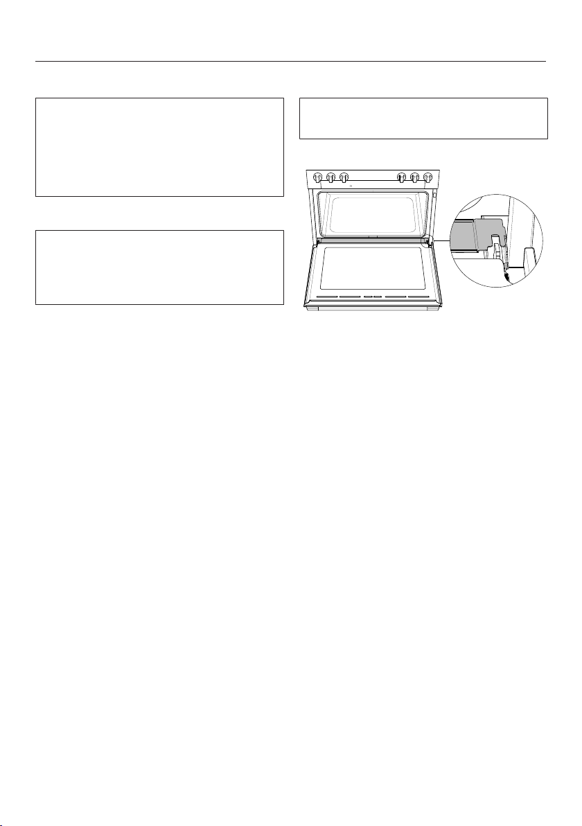
Installation of the drip tray
The drip tray covers the gap between
the oven cavity and the door.
Open the oven door.
Lay the drip tray over the gap
between the oven cavity and the
door.
Close the oven door.
16
Page 17
*INSTALLATION*
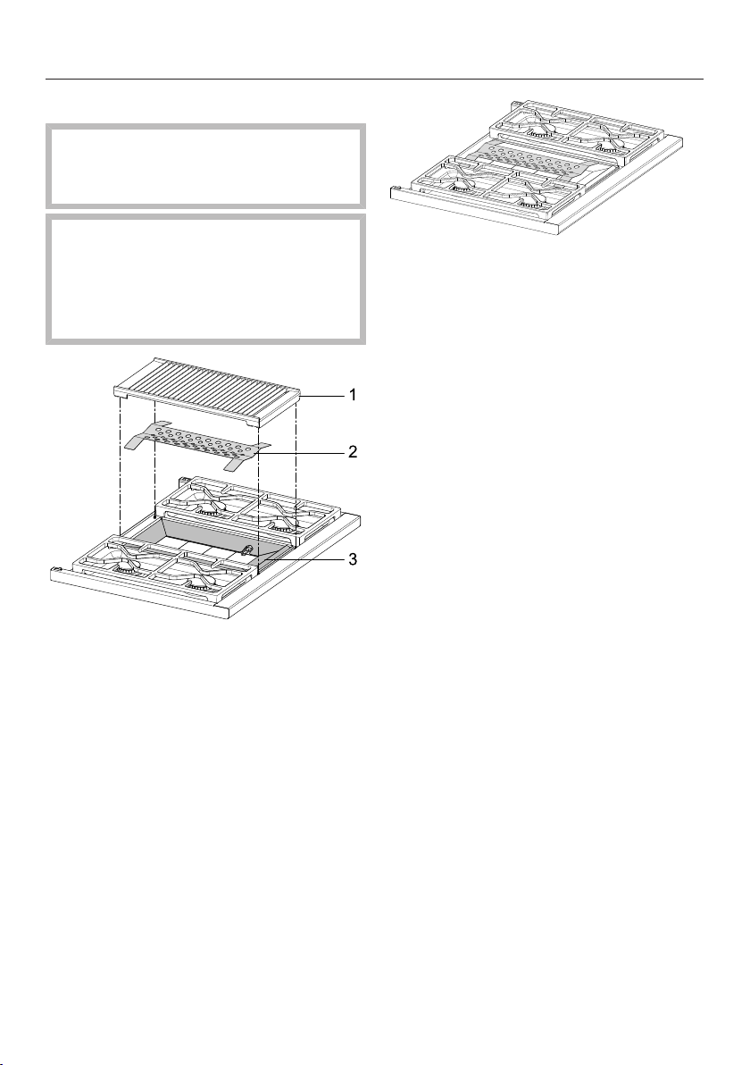
Assembling the grill
Burn hazard!
The burners must be turned off and
allowed to cool completely.
Risk of injury!
The cast-iron grill is heavy.
Carry the grill carefully and place it
securely on a soft base so that it lies
flat.
Notes on installation
Place the grill into position.
Cleaning and care
Tip: All parts can be disassembled in
the reverse order. You can also remove
the frame for cleaning.
a
Grill
b
Radiant plate
c
Frame
Using a soft sponge, clean radiant
plate with a solution of warm water
and a small amount of liquid dish
soap. Dry the parts thoroughly after
cleaning.
Remove the grill from the gas
cooktop.
Place the radiant plate on top of
the frame .
17
Page 18
*INSTALLATION*
Notes on installation
Optional accessories
All accessories and cleaning products
listed in these instructions are designed
to be used with the Miele range.
These can be ordered from the Miele
website (see end of this booklet for
contact details).
When ordering, please have your model
number available.
RBGAG All Gas Backguard/RBGDF Dual Fuel Backguard
Depending on the model, you can
exchange the existing island trim of
your appliance for a larger range
backguard. The backguard is available
in the following heights: 12“ (305 mm)
and 20” (508 mm).
All Gas Range
Risk of injury caused by hot vapors.
Hot vapors are emitted above the
island trim during Self Clean as well
as when cooking food in the oven.
You could burn yourself on the hot
vapors.
Do not reach above the island trim
and keep others away from it when
you are using the oven.
All Gas Range
Hot vapors are emitted above the
island trim during Self Clean as well
as when cooking food in the oven.
The emission of vapors can soil and
discolor surfaces above the island
trim.
Take precautions to protect sensitive
surfaces such as marble, granite,
and tiles against soiling and
discoloration (surfaces of this nature
can be difficult or even impossible to
clean).
18
Page 19
*INSTALLATION*
1
22
1 2 3
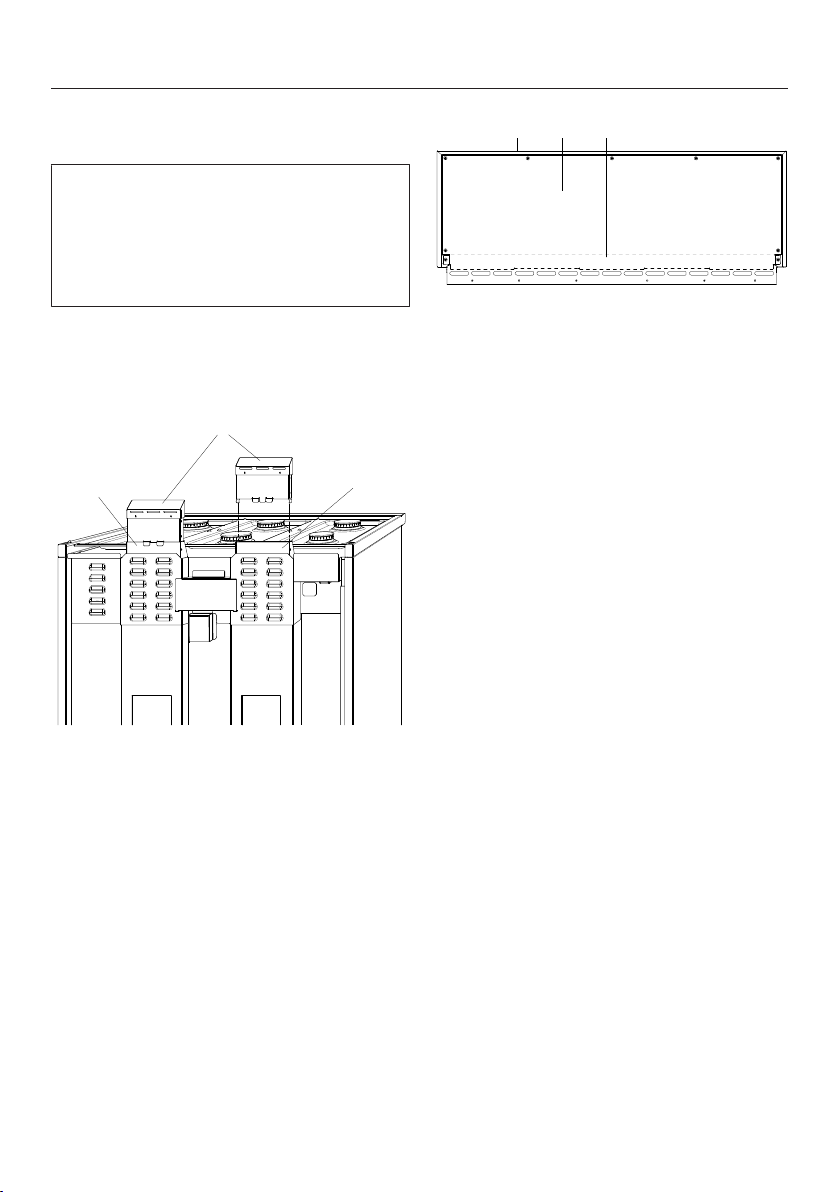
Mounting the RBGAG All Gas Backguard
The rear of the range must be
accessible.
Mount the backguard before installing
the anti-tip device and connecting of
the range.
Loosen the screws of the island trim.
Pull back the island trim slightly until
it can be removed.
Notes on installation
a
Backguard
b
Rear panel backguard
c
Interior panel
To avoid scratching the backguard
, place it front side downwards on a
soft surface (e.g., a blanket). The
lower edge should line up with the
edge of the table so that the
backguard is lying flat.
a
Extender
b
Air ducts
Insert one extender onto each of
the left and right air ducts .
Screw the extenders into place with
2 screws each.
Remove the screws from the rear of
the backguard.
Remove the rear and interior
panels.
19
Page 20
*INSTALLATION*
1
2
Notes on installation
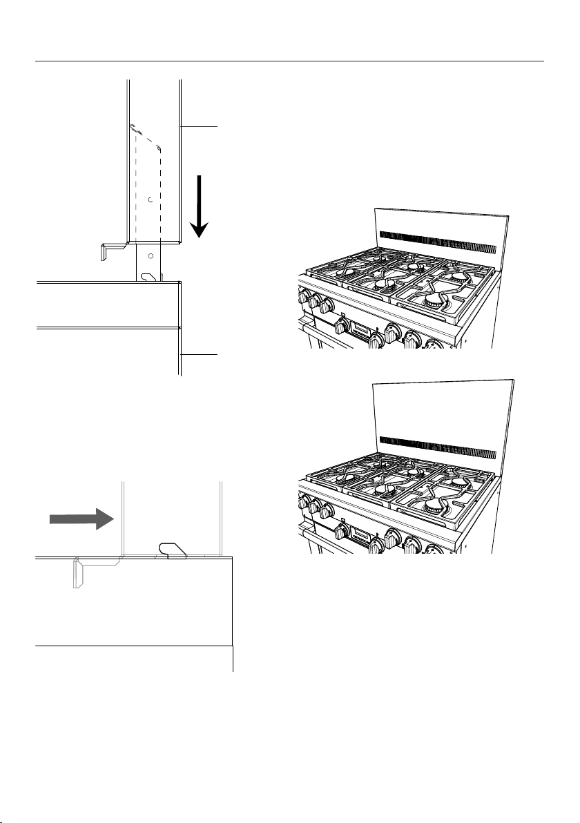
a
Backguard
b
Range
Secure the interior panel and the rear
panel to the backguard with the
screws supplied.
Secure the backguard to the range
with the screws supplied.
Backguard 12"
Push the backguard over the air
duct extensions from above.
As soon as the backguard is sitting
on the range, push the backguard
backwards.
20
Backguard 20"
Page 21

*INSTALLATION*
Notes on installation
Installing the RBGDF Dual Fuel Backguard
The rear of the range must be
accessible.
Install the backguard before installing
the anti-tip device and connecting of
the range.
Loosen the screws of the island trim.
Pull back the island trim slightly until
it can be removed.
The backguard can be installed in
reverse order.
RBS Backsplash
The backsplash is intended for
installation to a Miele Range Hood (DAR
model). Observe the installation
instructions of the Miele Range Hood.
XKM3000W Remote Vision (USA
Only)
Depending on the model, the range
maybe compatible with
RemoteVisionTM.
In order to use the RemoteVision
TM
monitoring service, you will require a
XKM3000W Communication Module.
Refer to the Operating and Installation
Instructions of the Miele XKM3000W
Communication Module.
21
Page 22
*INSTALLATION*
Notes on installation
Do not carry or lift the range by the oven door handle or the control panel!
The range is heavy.
Due to the size and weight of the appliance, installation should be performed by
two people.
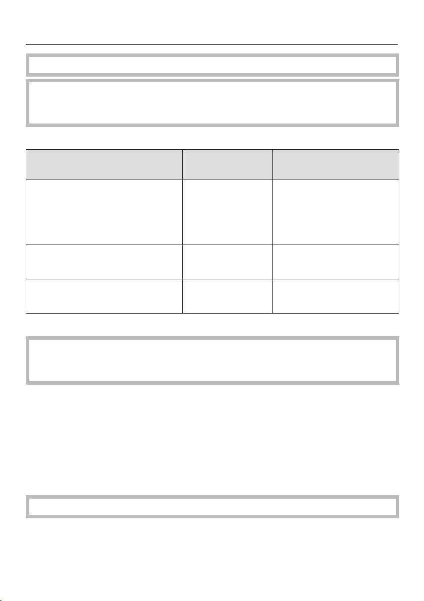
The net weight of the range with accessories is as follows:
Model Width Net weight incl.
accessories
HR 1421
HR 1622-2
HR 112x
2915/16""
(762mm)
approx.307lbs(140kg)
HR 1724
HR 192x-2
HR 113x-1
HR 193x-2
HR 195x-2 4715/16""
3515/16""
(915mm)
approx.405lbs(180kg)
approx.573lbs(260kg)
(1220mm)
Installation location
This appliance is not intended for outdoor use.
Ranges with a connection to the water supply should not be installed in rooms
where there is a risk of freezing temperatures.
The floor of the space where the appliance is to be installed must be flat, level and
made of a strong, rigid material.
The niche floor must be made of strong, rigid material.
Because the Range is heavy and has to be secured with the anti-tip device
supplied, the surface must be able to fully bear the load of the appliance. If
necessary, seek the advice of an architect or construction expert.
Ventilation
The air intake and outlet openings must not be covered or blocked in any way.
22
Page 23
*INSTALLATION*
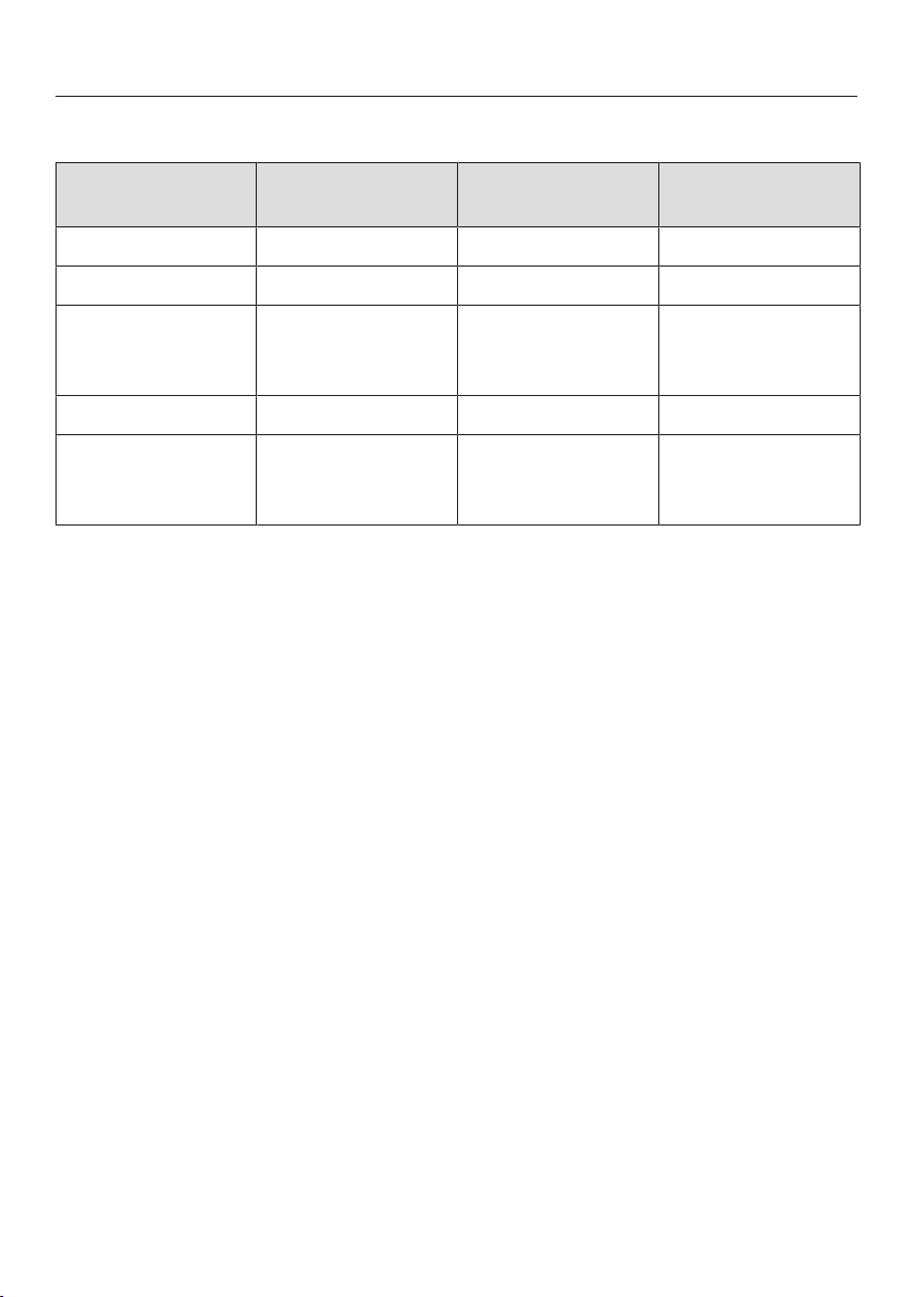
Required connections
Notes on installation
Model Electrical
connection
Gas connection Plumbed water
connection
HR 1421 Yes – –
HR 1622-2 Yes – Yes
HR 112x
Yes Yes –
HR 113x-1
HR 172x Yes Yes –
HR 192x-2
Yes Yes Yes
HR 193x-2
HR 195x-2
23
Page 24
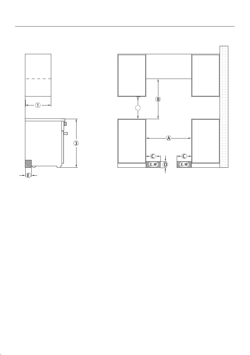
All Electric Range dimensions
2
HR 1421, HR 1622-2
, , The shaded area represents the installation area for the connections:
E = Electrical connection,
W = Plumbed water connection (HR 1622-2 only)
24
Page 25
All Electric Range dimensions
HR 1421, HR 1622-2
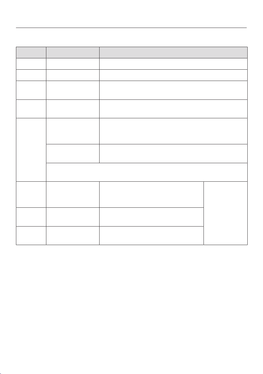
Position Dimensions Description
13" (330mm) Maximum depth of top cabinet
18" (547mm) Minimum distance to bottom edge of top cabinet
35 1/2"–37"
(901–940mm)
min. 30"
(762mm)
30" (762mm) Minimum distance between the top of the cooking
or 24" (609mm) Minimum distance to a protected combustible
For all other hoods please consult the manufacturer's specifications
for required distances.
approx. 4
approx. 2
Please observe a safe clearance distance of at least 12" (305mm) from combustible
surfaces located behind the appliance. For zero clearance installation the Miele Backguards
will satisfy the required distance to combustible surfaces. The Miele Backguard is available
in 12"(305mm) or 20"(508mm) heights.
approx.
101/16"
(256mm)
1/2" (115mm)
13/16" (72mm)
Distance from the floor to cooktop surface
Niche width
area and the bottom of an unprotected
combustible surface.
surface or when a Miele Range Hood is installed.
Maximum connection width right
and left
Maximum connection height
Maximum connection depth
Position of
the wall
socket
25
Page 26
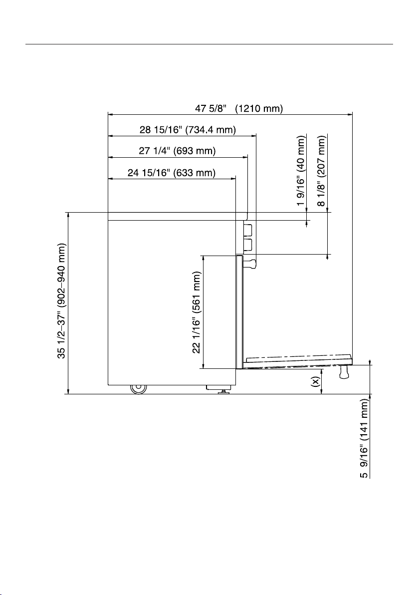
All Electric Range dimensions
Detailed views of HR 1421
Side view of HR 1421
(x) = Depending on the appliance height adjustment
5" - 61/2" (127 mm - 165.1 mm)
26
Page 27
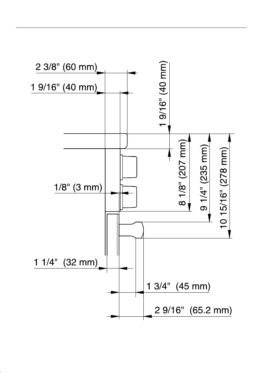
Detailed front side view of HR 1421
All Electric Range dimensions
27
Page 28
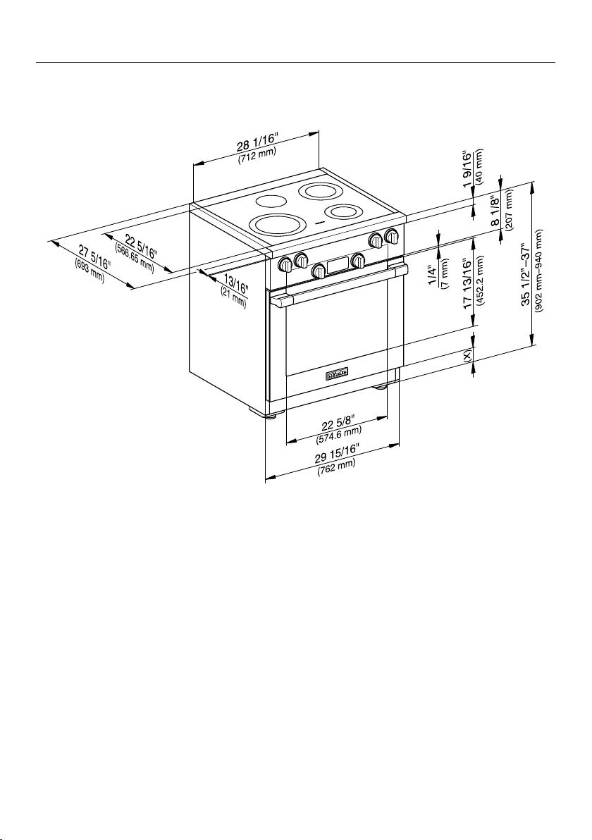
All Electric Range dimensions
Front side view of HR 1421
(x) = Depending on the appliance height adjustment
5" - 61/2" (127 mm - 165.1 mm)
28
Page 29
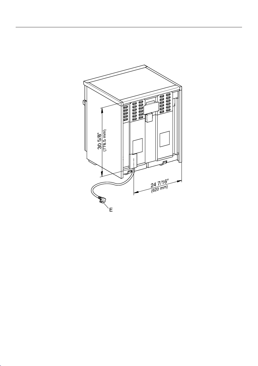
Rear view of HR 1421
All Electric Range dimensions
E = Electrical connection
29
Page 30
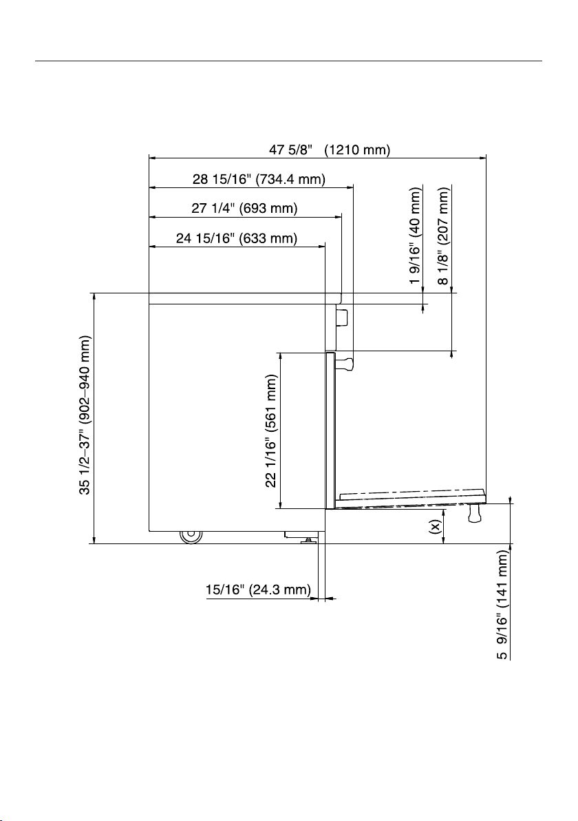
All Electric Range dimensions
Detailed views of HR 1622-2
Side view of HR 1622-2
(x) = Depending on the appliance height adjustment: 5" - 6 1/2" (127mm -
165.1mm)
30
Page 31
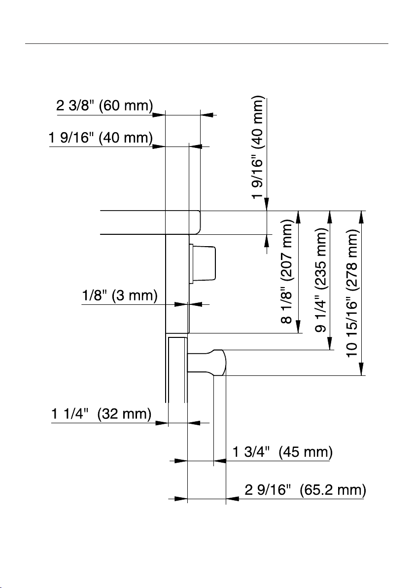
Detailed front side view of HR 1622-2
All Electric Range dimensions
31
Page 32
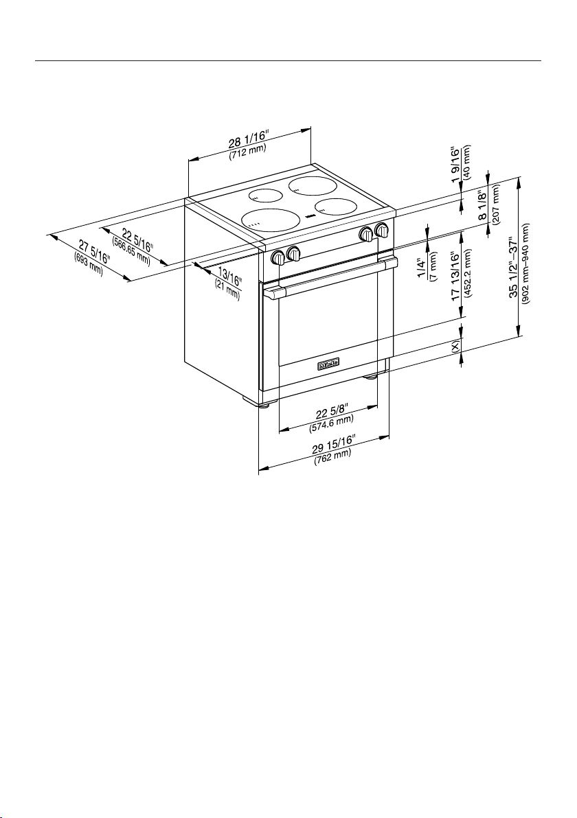
All Electric Range dimensions
Front view of HR 1622-2
(x) = Depending on the appliance height adjustment: 5" - 6 1/2" (127mm -
165.1mm)
32
Page 33
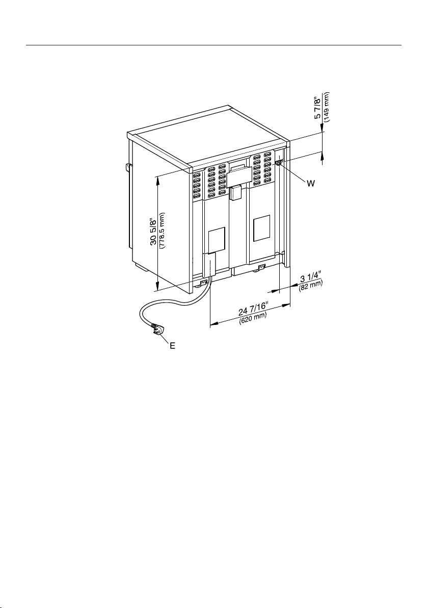
Rear view of HR 1622-2
All Electric Range dimensions
E = Electrical connection
W = Water connection
33
Page 34
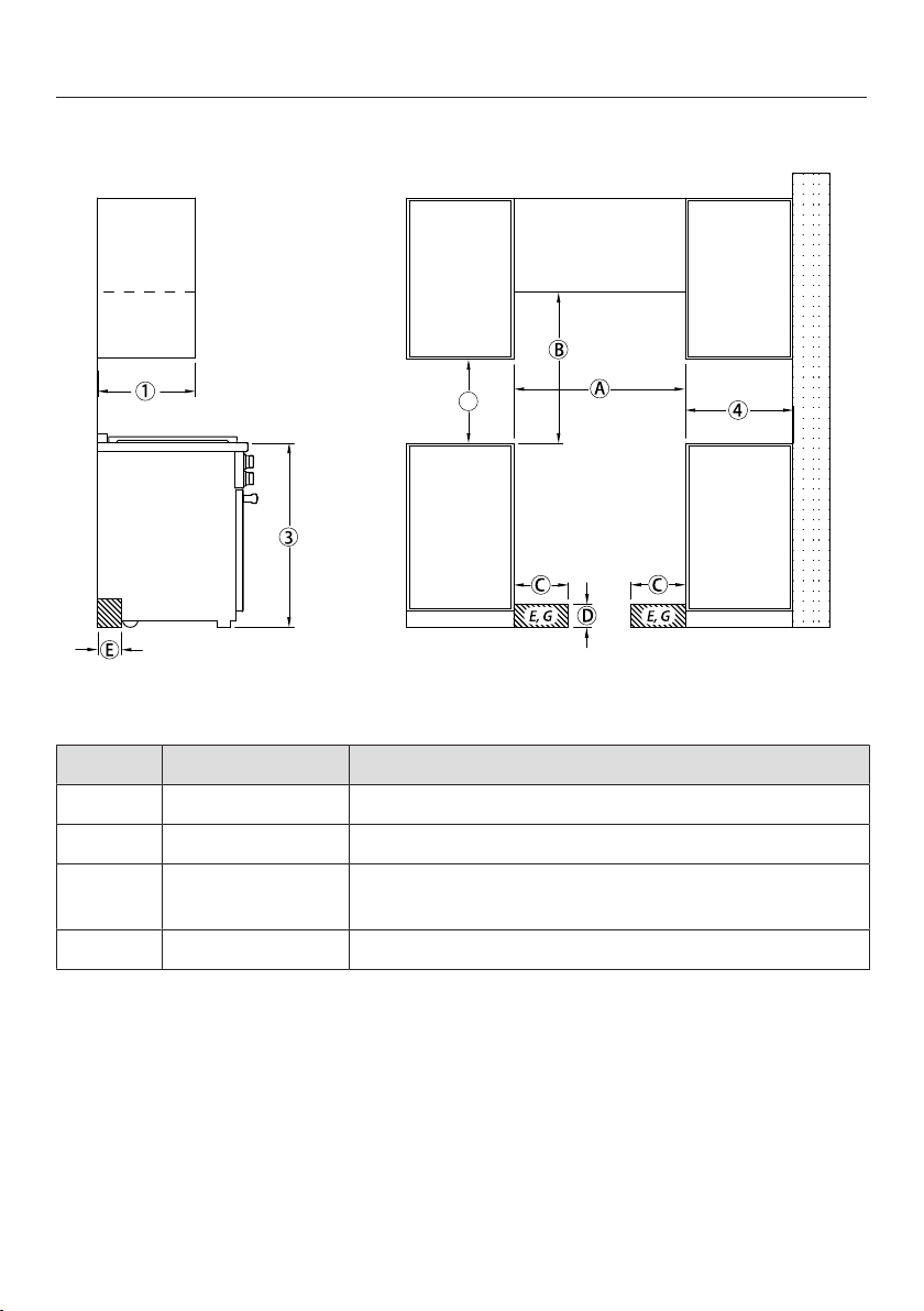
All Gas Range dimensions
2
All Gas Range HR 1124
, , The shaded area represents the installation area for the connections:
E = Electrical connection, G = Gas connection
Position Dimensions Description
13" (330mm) Maximum depth of top cabinet
18" (457mm) Minimum distance to bottom edge of top cabinet
35 1/2"–37"
(901–940mm)
10" (254mm) Minimum distance to combustible surfaces.
34
Distance from the floor to cooktop surface
Page 35
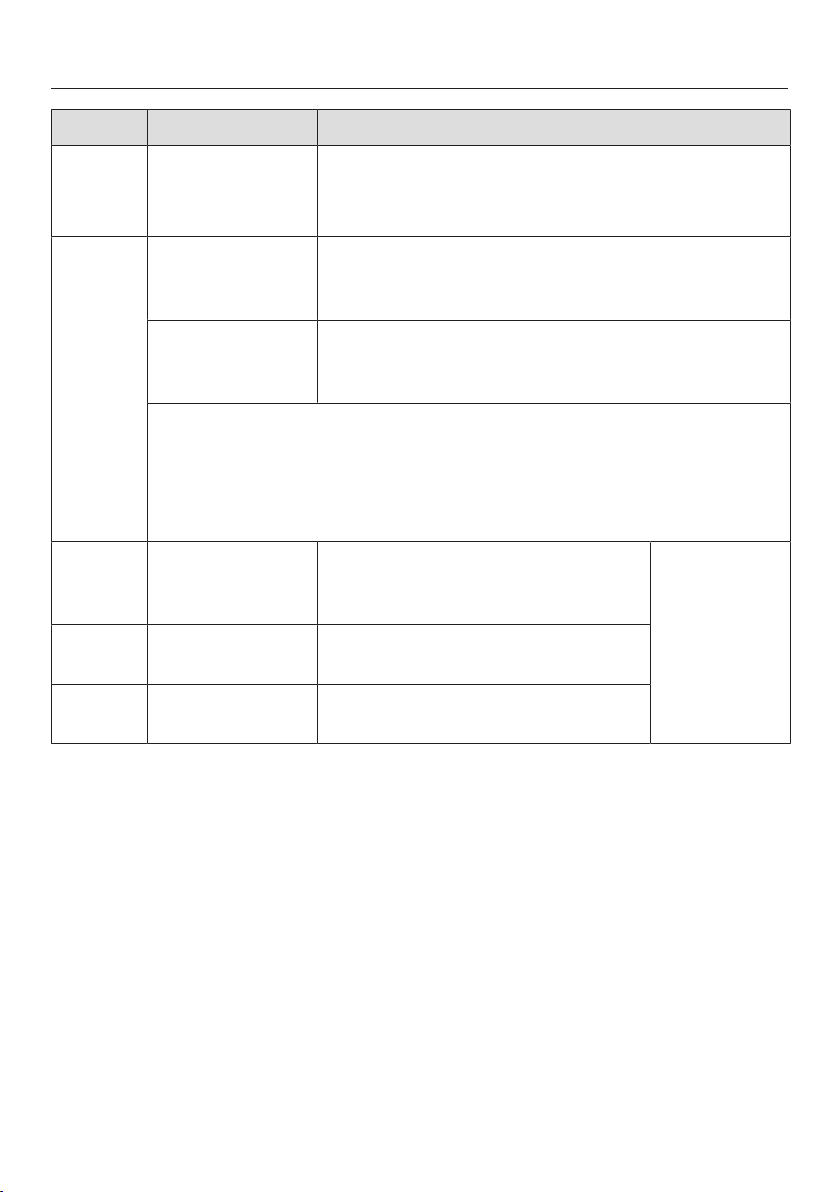
Position Dimensions Description
All Gas Range dimensions
min. 30"
(762mm)
Niche width
Please contact Miele Technical Service for more
information.
37" (940mm) Minimum distance between the top of the cooking
area and the bottom of an unprotected
combustible surface.
30" (762mm) Minimum distance between the top of the cooking
area and the bottom of the Miele Range Hood
(DAR model with DRxB XL or DRxB XXL blower).
Refer to the Installation instructions for the Miele ventilation hood,
Appliance dimensions (Distance between cooktop and ventilation
hood (S)).
For all other hoods please consult the manufacturer's specifications
for required distances.
approx.
101/16"
(256mm)
approx.
Maximum connection width right
and left
Maximum connection height
Position of
the wall
socket
41/2" (115mm)
approx.
Maximum connection depth
213/16" (72mm)
Please observe safe distances to rear combustible surfaces of 12" (305mm) clearance. For
zero clearance installation the Miele Backguards will satisfy the required distance to
combustible surfaces. The Miele Backguard is available in 12" (305mm) or 20" (508mm)
heights.
35
Page 36
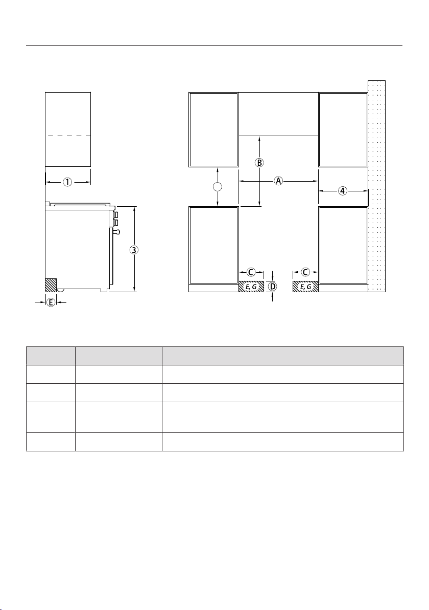
All Gas Range dimensions
2
All Gas Range HR1134-1, HR1135-1, HR1136-1
, , The shaded area represents the installation area for the connections:
E = Electrical connection, G = Gas connection
Position Dimensions Description
13" (330mm) Maximum depth of top cabinet
18" (457mm) Minimum distance to bottom edge of top cabinet
35 1/2"–37"
(901–940mm)
10" (254mm) Minimum distance to combustible surfaces.
36
Distance from the floor to cooktop surface
Page 37
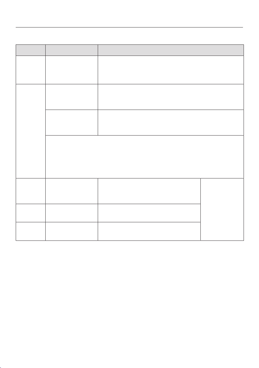
HR 1134-1, HR 1135-1, HR 1136-1
Position Dimensions Description
All Gas Range dimensions
min. 36"
(915mm)
Niche width
Please contact Miele Technical Service for more
information.
37" (940mm) Minimum distance between the top of the cooking
area and the bottom of an unprotected
combustible surface.
30" (762mm) Minimum distance between the top of the cooking
area and the bottom of the Miele Range Hood
(DAR model with DRxB XL or DRxB XXL blower).
Refer to the Installation instructions for the Miele ventilation hood,
Appliance dimensions (Distance between cooktop and ventilation
hood (S)).
For all other hoods please consult the manufacturer's specifications
for required distances.
approx.
131/16"
(332.5 mm)
approx.
Maximum connection width right
and left
Maximum connection height
Position of
the wall
socket
41/2" (115mm)
approx.
Maximum connection depth
213/16" (72mm)
Please observe safe distances to rear combustible surfaces of 12" (305mm) clearance. For
zero clearance installation the Miele Backguards will satisfy the required distance to
combustible surfaces. The Miele Backguard is available in 12" (305mm) or 20" (508mm)
heights.
37
Page 38
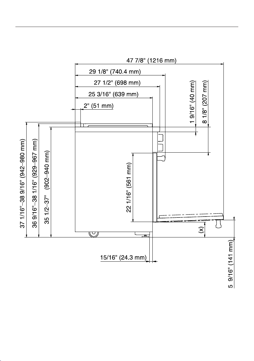
All Gas Range dimensions
Detailed views of HR 1124
Side view of HR 1124
(x) = Depending on the appliance height adjustment: 5" - 6 1/2" (127 mm - 165.1
mm)
38
Page 39
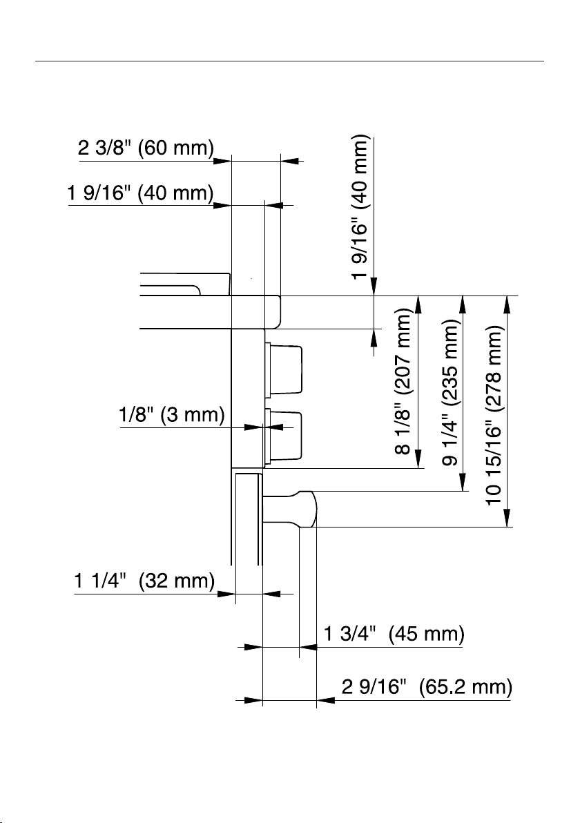
Detailed front side view of HR 1124
All Gas Range dimensions
39
Page 40
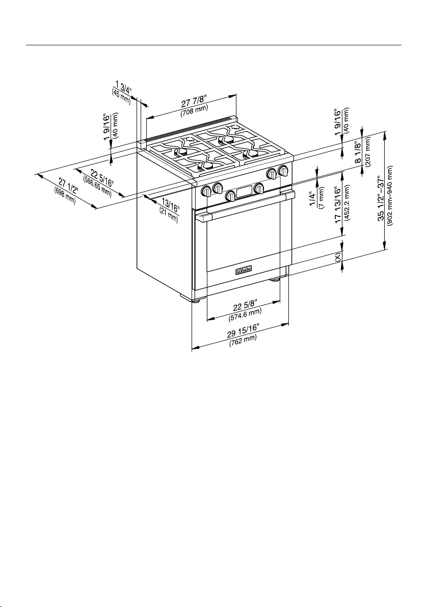
All Gas Range dimensions
Front side view of HR 1124
(x) = Depending on the appliance height adjustment: 5" - 6 1/2" (127 mm - 165.1
mm)
40
Page 41
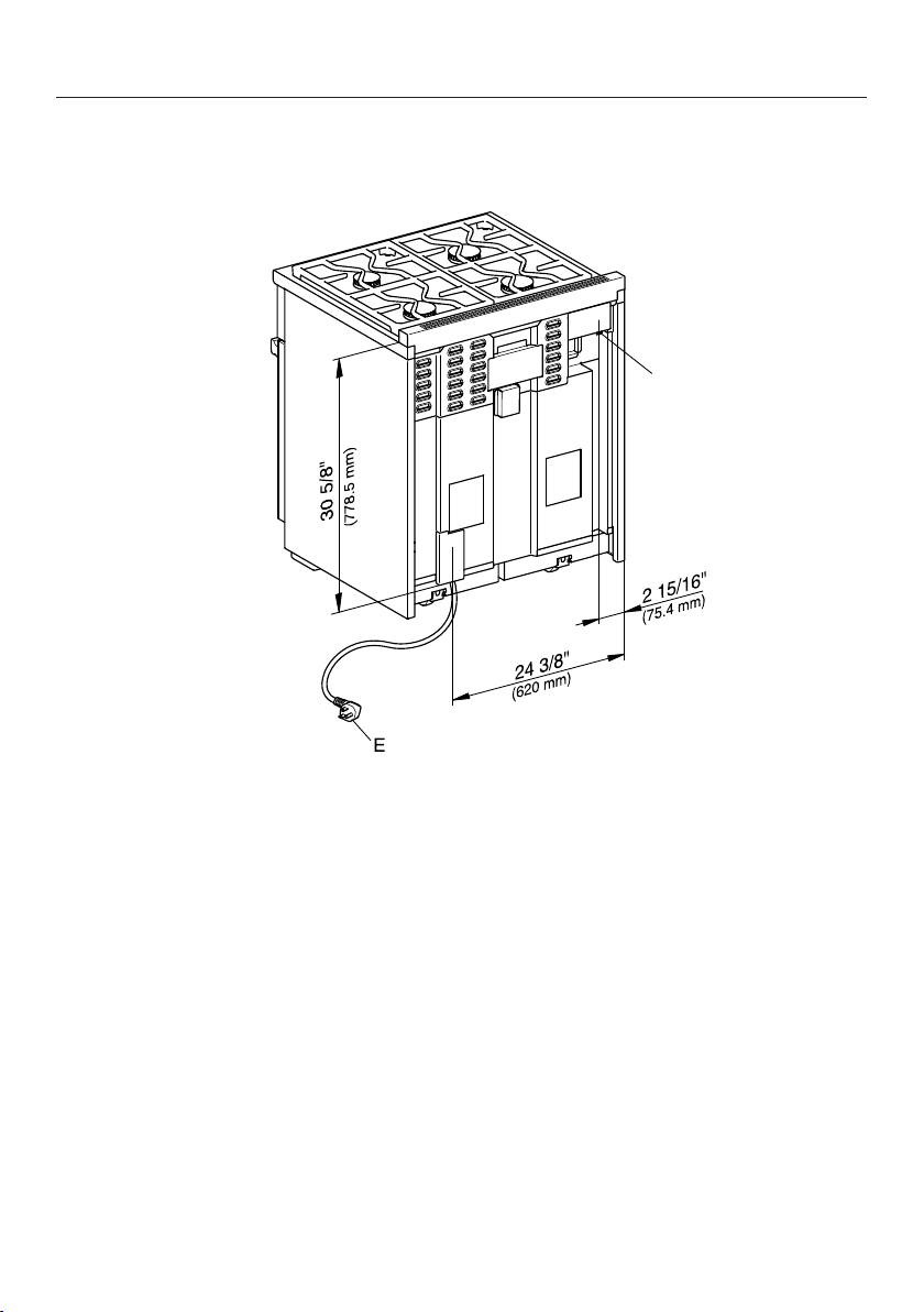
Rear view of HR 1124
G
All Gas Range dimensions
E = Electrical connection
G = Gas connection
41
Page 42
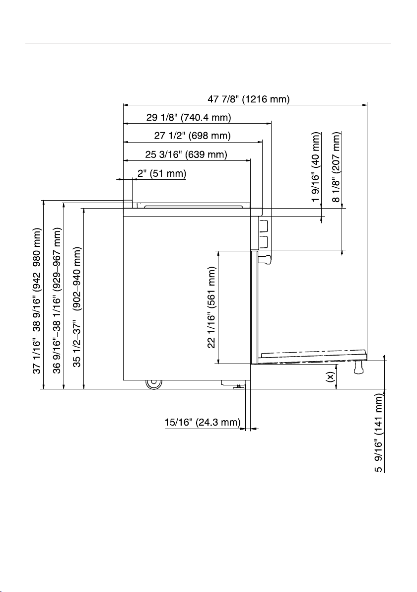
All Gas Range dimensions
Detailed views of HR 1134-1
Side view of HR 1134-1
(x) = Depending on the appliance height adjustment: 5" - 61/2" (127mm -
165.1mm)
42
Page 43
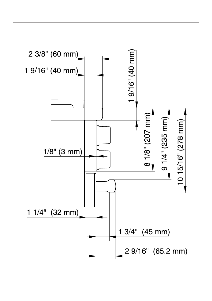
Detailed front side view of HR 1134-1
All Gas Range dimensions
43
Page 44
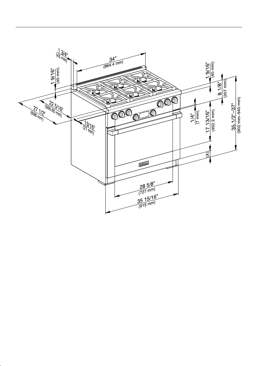
All Gas Range dimensions
Front view of HR 1134-1
(x) = Depending on the appliance height adjustment: 5" - 61/2" (127mm -
165.1mm)
44
Page 45
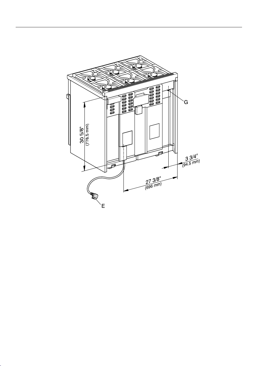
Rear view of HR 1134-1
All Gas Range dimensions
E = Electrical connection
G = Gas connection
45
Page 46
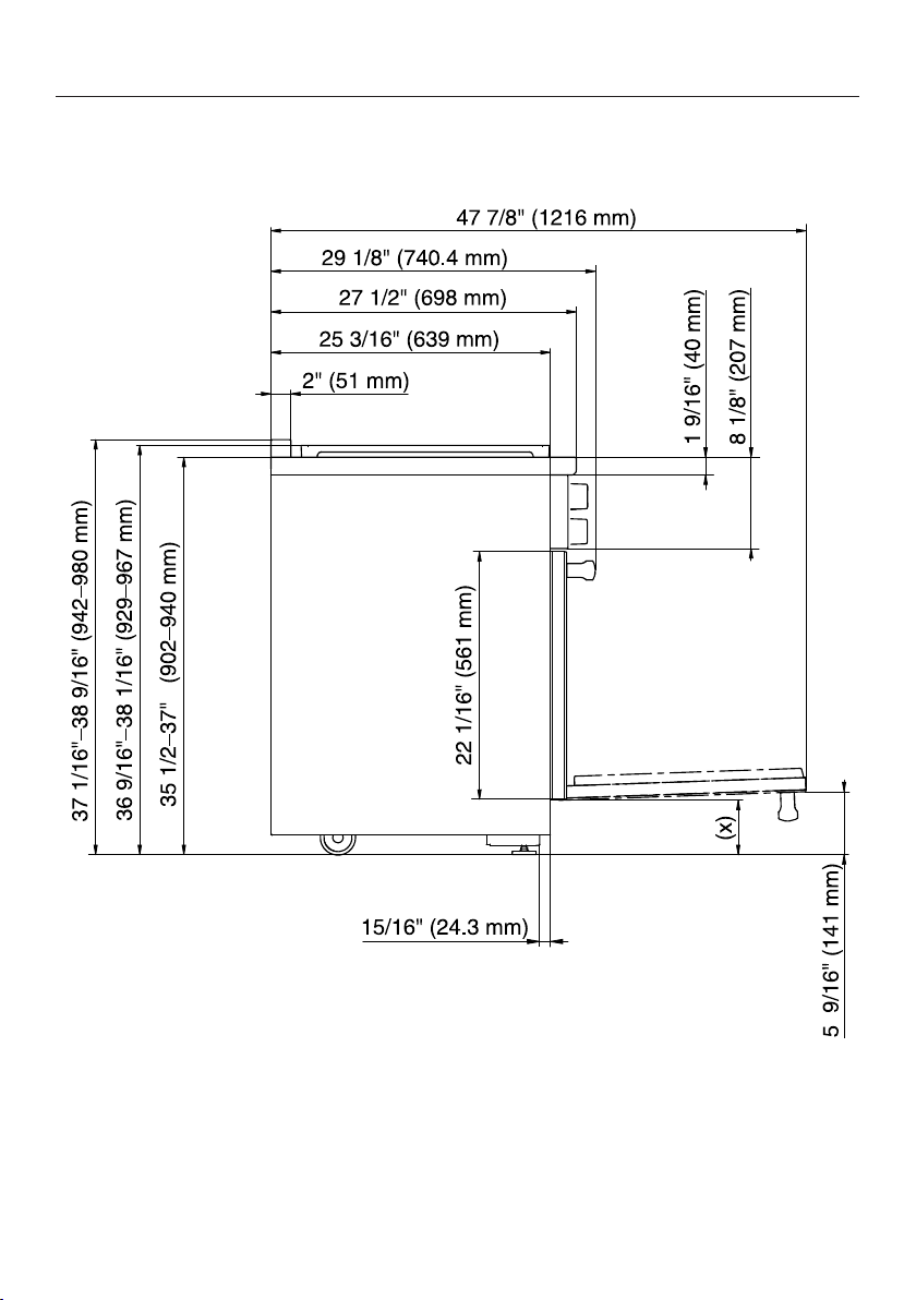
All Gas Range dimensions
Detailed views of HR 1135-1
Side view of HR 1135-1
(x) = Depending on the appliance height adjustment: 5" - 61/2" (127mm -
165.1mm)
46
Page 47
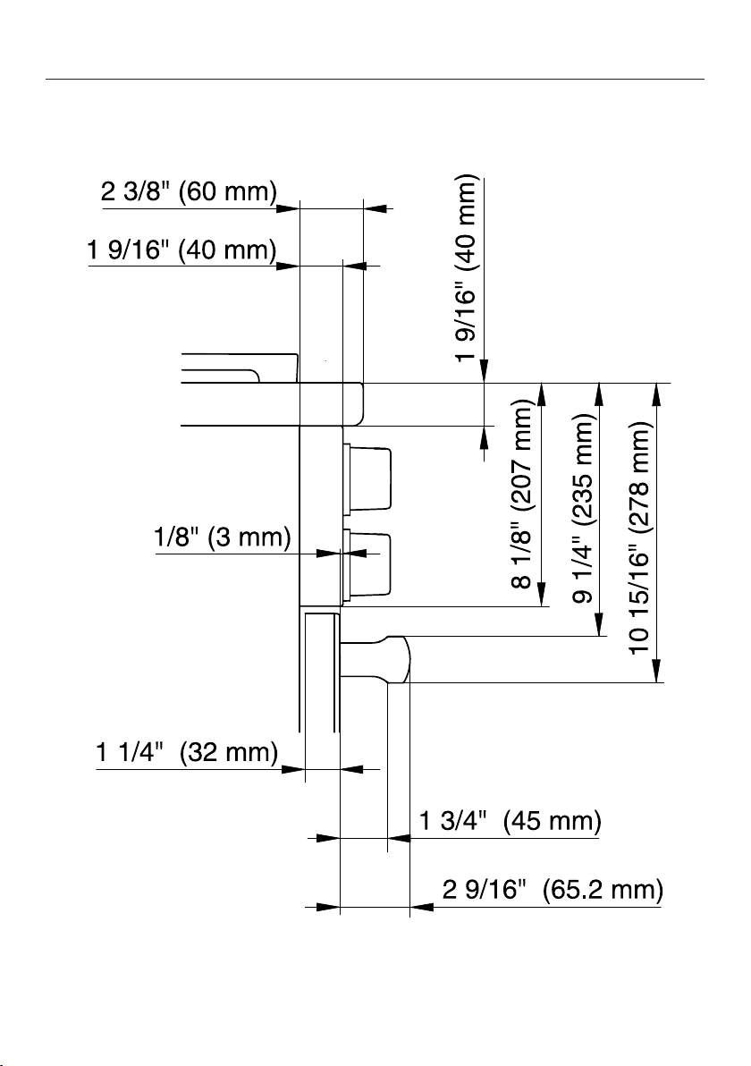
Detailed front side view of HR 1135-1
All Gas Range dimensions
47
Page 48
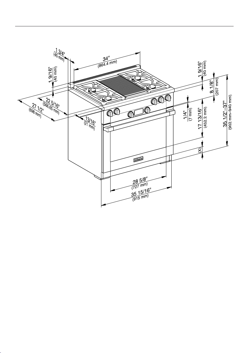
All Gas Range dimensions
Front view of HR 1135-1
(x) = Depending on the appliance height adjustment: 5" - 61/2" (127mm -
165.1mm)
48
Page 49
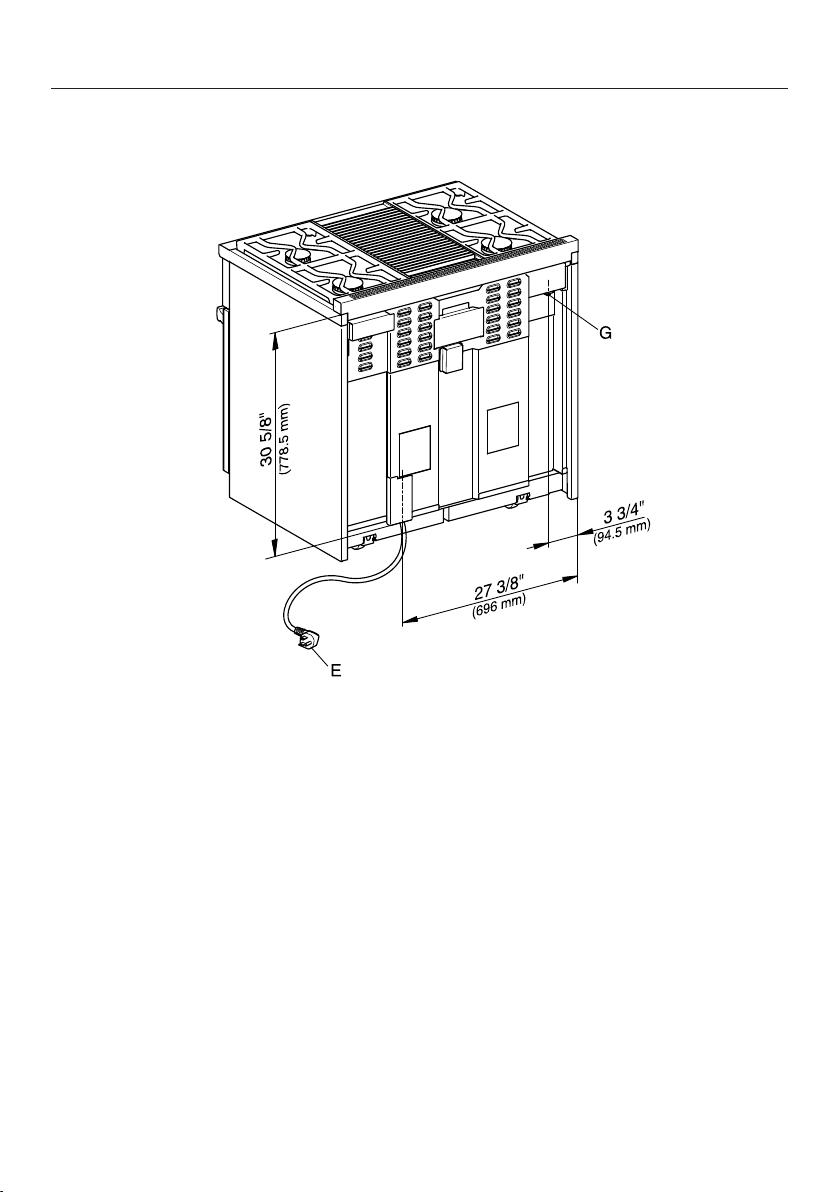
Rear view of HR 1135-1
All Gas Range dimensions
E = Electrical connection
G = Gas connection
49
Page 50
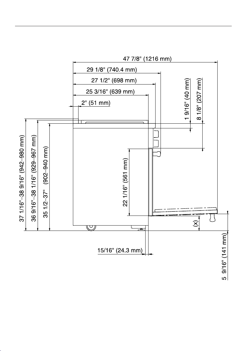
All Gas Range dimensions
Detailed views of HR 1136-1
Side view of HR 1136-1
(x) = Depending on the appliance height adjustment: 5" - 61/2" (127mm -
165.1mm)
50
Page 51
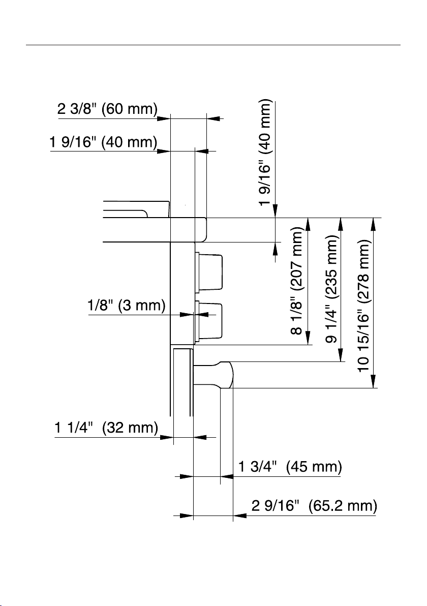
Detailed front side view of HR 1136-1
All Gas Range dimensions
51
Page 52
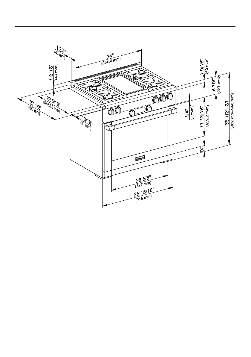
All Gas Range dimensions
Front view of HR 1136-1
(x) = Depending on the appliance height adjustment: 5" - 61/2" (127mm -
165.1mm)
52
Page 53
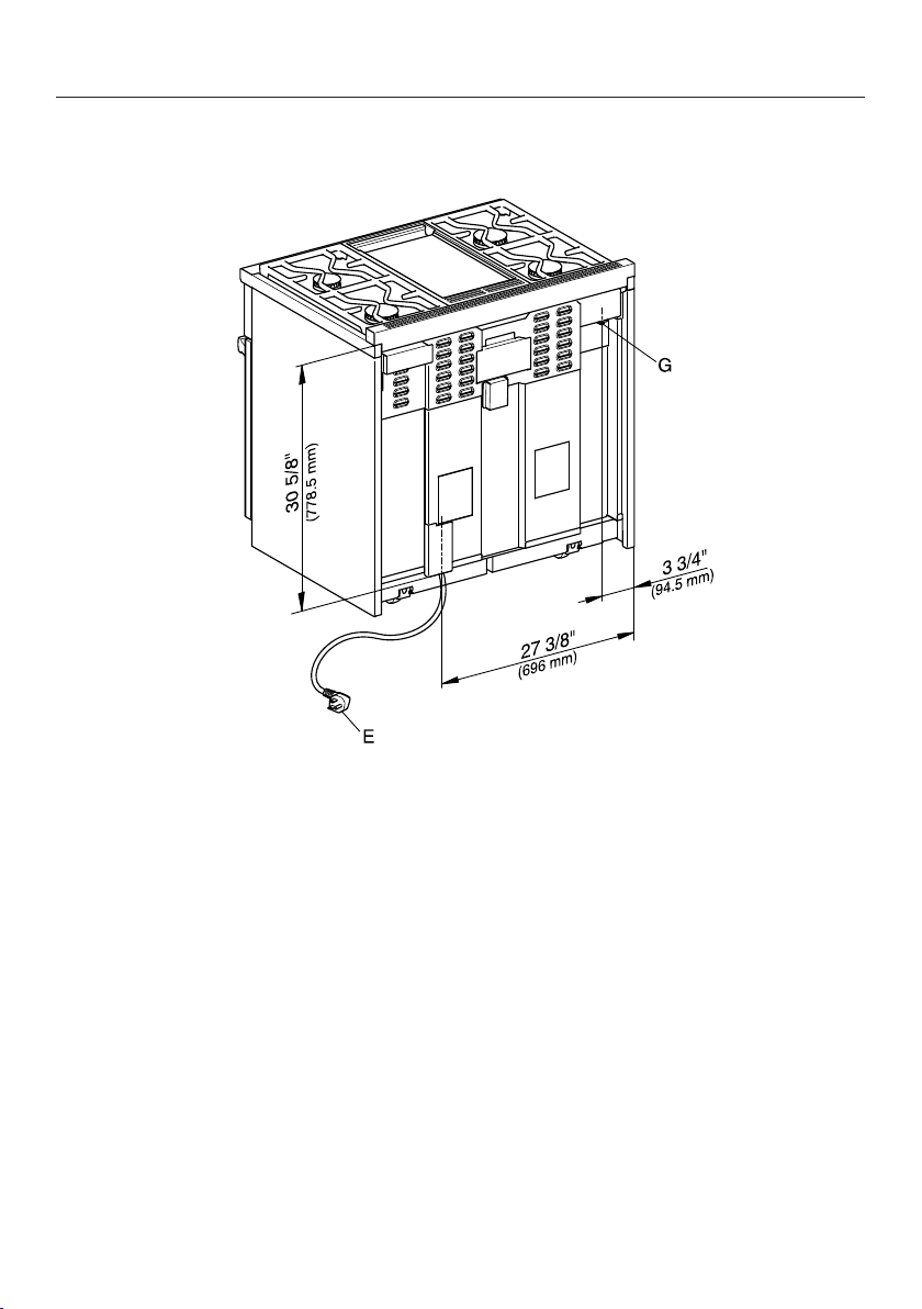
Rear view of HR 1136-1
All Gas Range dimensions
E = Electrical connection
G = Gas connection
53
Page 54
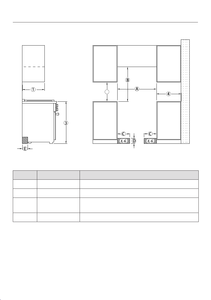
Dual Fuel Range dimensions
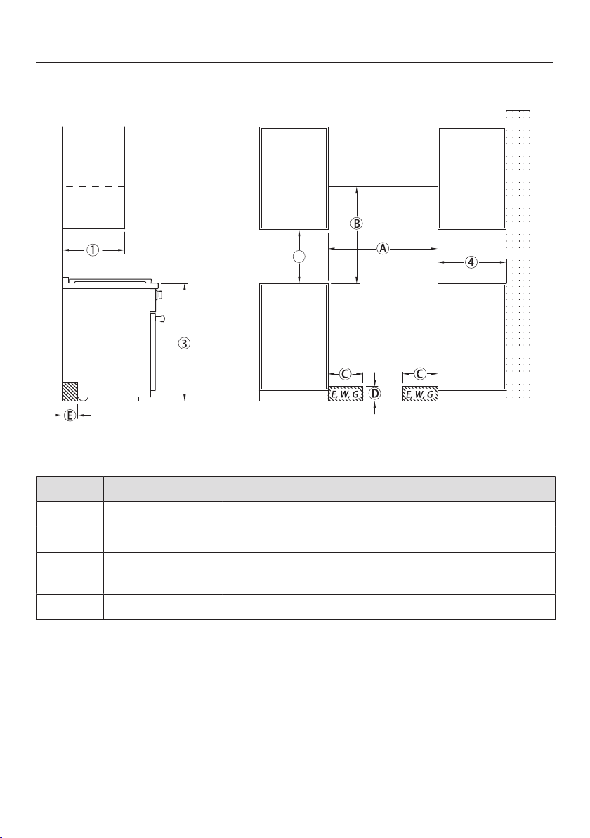
2
Dual Fuel Range HR 1724
, , The shaded area represents the installation area for the connections:
E = Electrical connection, G = Gas connection
Position Dimensions Description
13" (330mm) Maximum depth of top cabinet
18" (457mm) Minimum distance to bottom edge of top cabinet
35 1/2"–37"
(901–940mm)
10" (254mm) Minimum distance to combustible surfaces.
54
Distance from the floor to cooktop surface
Page 55
Dual Fuel Range dimensions
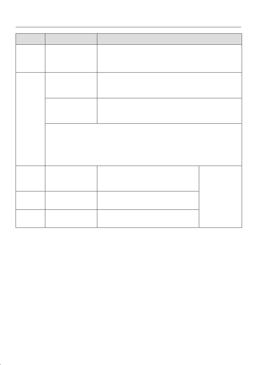
Position Dimensions Description
min. 30"
(762mm)
Niche width
Please contact Miele Technical Service for more
information.
37" (940mm) Minimum distance between the top of the cooking
area and the bottom of an unprotected
combustible surface.
30" (762mm) Minimum distance between the top of the cooking
area and the bottom of the Miele Range Hood
(DAR model with DRxB XL or DRxB XXL blower).
Refer to the Installation instructions for the Miele ventilation hood,
Appliance dimensions (Distance between cooktop and ventilation
hood (S)).
For all other hoods please consult the manufacturer's specifications
for required distances.
approx.
101/16"
(256mm)
approx.
Maximum connection width right
and left
Maximum connection height
Position of
the wall
socket
41/2" (115mm)
approx.
Maximum connection depth
213/16" (72mm)
Please observe safe distances to rear combustible surfaces of 12" (305mm) clearance. For
zero clearance installation the Miele Backguards will satisfy the required distance to
combustible surfaces. The Miele Backguard is available in 12" (305mm) or 20" (508mm)
heights.
55
Page 56
Dual Fuel Range dimensions
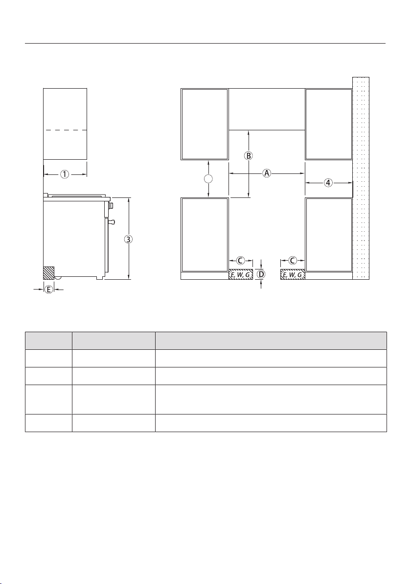
2
Dual Fuel Range HR 1924-2
, , The shaded area represents the installation area for the connections:
E = Electrical connection, W = Plumbed water connection, G = Gas connection
Position Dimensions Description
13" (330mm) Maximum depth of top cabinet
18" (457mm) Minimum distance to bottom edge of top cabinet
35 1/2"–37"
(901–940mm)
10" (254mm) Minimum distance to combustible surfaces.
56
Distance from the floor to cooktop surface
Page 57
Dual Fuel Range dimensions
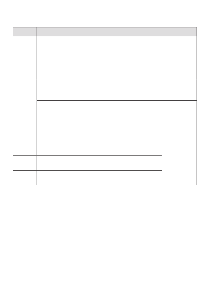
Position Dimensions Description
min. 30"
(762mm)
Niche width
Please contact Miele Technical Service for more
information.
37"(940mm) Minimum distance between the top of the cooking
area and the bottom of an unprotected
combustible surface.
30"(762mm) Minimum distance between the top of the cooking
area and the bottom of the Miele Range Hood
(DAR model with DRxB XL or DRxB XXL blower).
Refer to the installation instructions for the Miele Range Hood,
Appliance dimensions (Distance between cooktop and ventilation
hood (S)).
For all other hoods please consult the manufacturer's specifications
for required distances.
approx.
101/16"
(256mm)
approx. 4 1/2"
Maximum connection width right
and left
Maximum connection height
Position of
the wall
socket
(115 mm)
approx.213/16"
Maximum connection depth
(72mm)
Please observe a safe clearance distance of at least 12" (305mm) from combustible
surfaces located behind the appliance. For zero clearance installation the Miele Backguards
will satisfy the required distance to combustible surfaces. The Miele Backguard is available
in 12"(305mm) or 20"(508mm) heights.
57
Page 58
Dual Fuel Range dimensions
2
Dual Fuel Range HR 1934-2, HR 1935-2, HR 1936-2
, , The shaded area represents the installation area for the connections:
E = Electrical connection, W = Plumbed water connection, G = Gas connection
Position Dimensions Description
13" (330mm) Maximum depth of top cabinet
18" (457mm) Minimum distance to bottom edge of top cabinet
35 1/2"–37"
(901–940mm)
10" (254mm) Minimum distance to combustible surfaces.
58
Distance from the floor to cooktop surface
Page 59
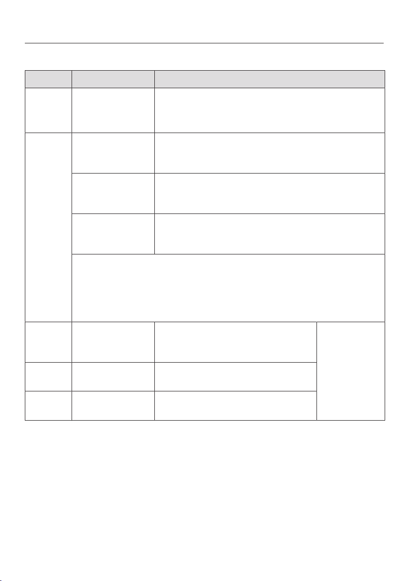
HR 1934-2
Position Dimensions Description
Dual Fuel Range dimensions
min. 36"
(915mm)
Niche width
Please contact Miele Technical Service for more
information.
37"(940mm) Minimum distance between the top of the cooking
area and the bottom of an unprotected
combustible surface.
36"(915mm) Minimum distance between the top of the cooking
area and the bottom of the Miele Range Hood
(DAR model with DRxB XL blower).
30"(762mm) Minimum distance between the top of the cooking
area and the bottom of the Miele Range Hood
(DAR model with DRxB XXL blower).
Refer to the installation instructions for the Miele Range Hood,
Appliance dimensions (Distance between cooktop and ventilation
hood (S)).
For all other hoods please consult the manufacturer's specifications
for required distances.
approx.
131/16"
(332.5 mm)
approx. 4 1/2"
Maximum connection width right
and left
Maximum connection height
Position of
the wall
socket
(115 mm)
approx.213/16"
Maximum connection depth
(72mm)
Please observe a safe clearance distance of at least 12" (305mm) from combustible
surfaces located behind the appliance. For zero clearance installation the Miele Backguards
will satisfy the required distance to combustible surfaces. The Miele Backguard is available
in 12"(305mm) or 20"(508mm) heights.
59
Page 60
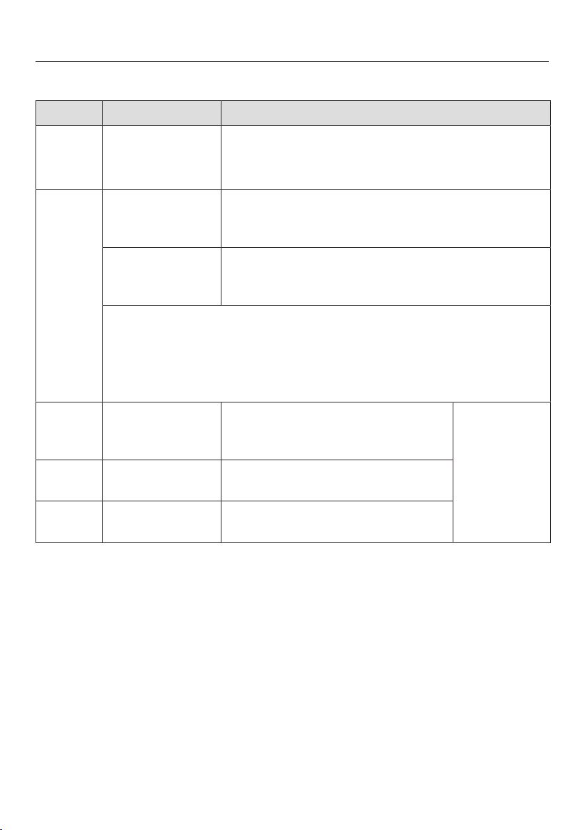
Dual Fuel Range dimensions
HR 1935-2, HR 1936-2
Position Dimensions Description
min. 36"
(915mm)
Niche width
Please contact Miele Technical Service for more
information.
37"(940mm) Minimum distance between the top of the cooking
area and the bottom of an unprotected
combustible surface.
30"(762mm) Minimum distance between the top of the cooking
area and the bottom of the Miele Range Hood
(DAR model with DRxB XL or DRxB XXL blower).
Refer to the installation instructions for the Miele Range Hood,
Appliance dimensions (Distance between cooktop and ventilation
hood (S)).
For all other hoods please consult the manufacturer's specifications
for required distances.
approx.
131/16"
(332.5 mm)
approx. 4 1/2"
Maximum connection width right
and left
Maximum connection height
Position of
the wall
socket
(115 mm)
approx.213/16"
Maximum connection depth
(72mm)
Please observe a safe clearance distance of at least 12" (305mm) from combustible
surfaces located behind the appliance. For zero clearance installation the Miele Backguards
will satisfy the required distance to combustible surfaces. The Miele Backguard is available
in 12"(305mm) or 20"(508mm) heights.
60
Page 61
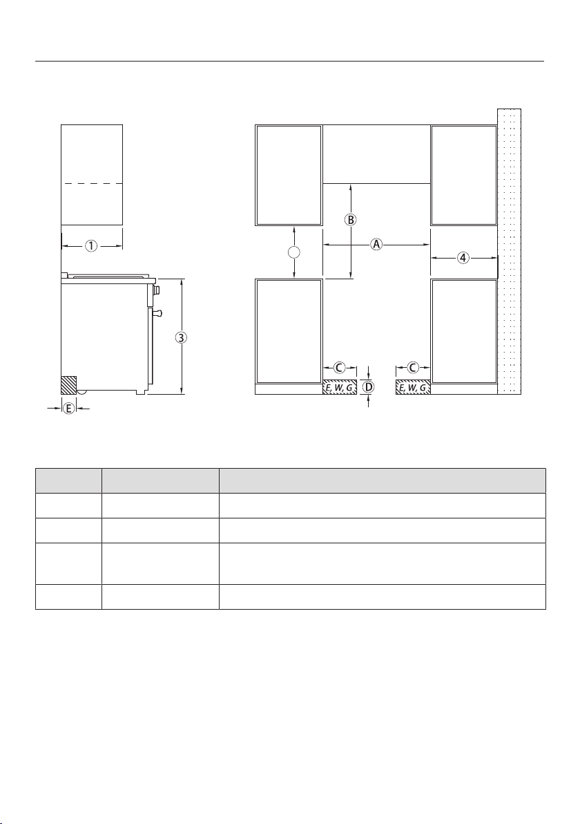
Dual Fuel Range dimensions
2
Dual Fuel Range HR 1954-2, HR 1955-2, HR 1956-2
, , The shaded area represents the installation area for the connections:
E = Electrical connection, W = Plumbed water connection, G = Gas connection
Position Dimensions Description
13" (330mm) Maximum depth of top cabinet
18" (457mm) Minimum distance to bottom edge of top cabinet
35 1/2"–37"
(901–940mm)
10" (254mm) Minimum distance to combustible surfaces.
Distance from the floor to cooktop surface
61
Page 62
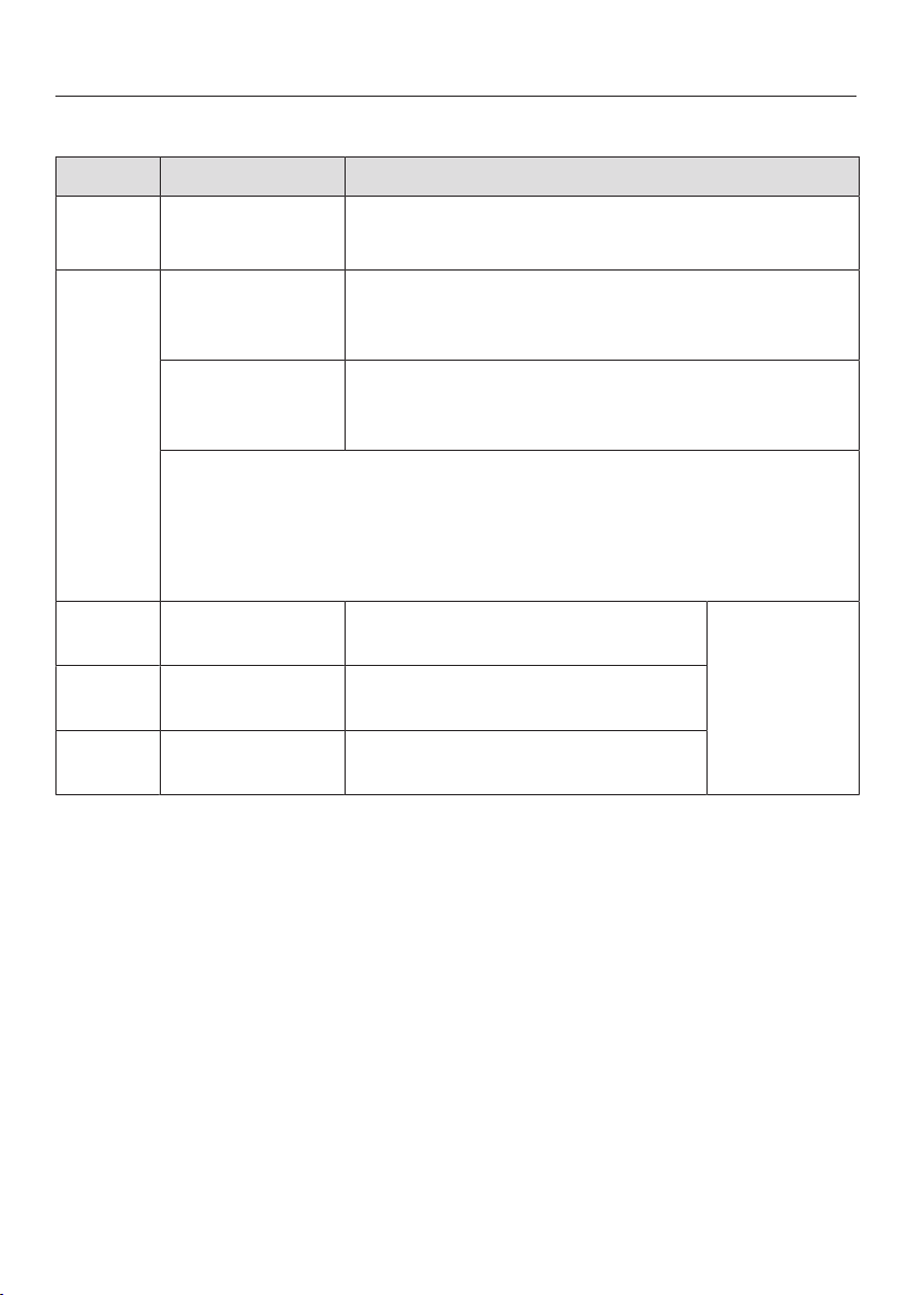
Dual Fuel Range dimensions
HR 1954-2
Position Dimensions Description
min. 48"
(1220mm)
Niche width
Please contact Miele Service for more information.
37"(940mm) Minimum distance between the top of the cooking
area and the bottom of an unprotected
combustible surface.
36"(915mm) Minimum distance between the top of the cooking
area and the bottom of the Miele Range Hood
(DAR model with DRxB XXL blower).
Refer to the installation instructions for the Miele Range Hood,
Appliance dimensions (Distance between cooktop and ventilation
hood (S)).
For all other hoods please consult the manufacturer's specifications
for required distances.
approx.
191/8" (485mm)
approx.
Maximum connection width right
and left
Maximum connection height
Position of
the wall
socket
31/2" (90mm)
approx.213/16"
Maximum connection depth
(72mm)
Please observe a safe clearance distance of at least 12" (305mm) from combustible
surfaces located behind the appliance. For zero clearance installation the Miele Backguards
will satisfy the required distance to combustible surfaces. The Miele Backguard is available
in 12"(305mm) or 20"(508mm) heights.
62
Page 63
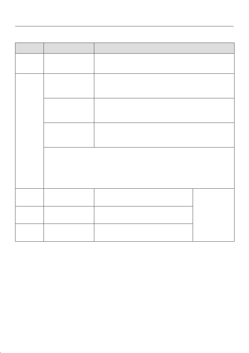
HR 1955-2, HR 1956-2
Position Dimensions Description
Dual Fuel Range dimensions
min. 48"
(1220mm)
Niche width
Please contact Miele Service for more information.
37"(940mm) Minimum distance between the top of the cooking
area and the bottom of an unprotected
combustible surface.
36"(915mm) Minimum distance between the top of the cooking
area and the bottom of the Miele Range Hood
(DAR model with DRxB XL blower).
30"(762mm) Minimum distance between the top of the cooking
area and the bottom of the Miele Range Hood
(DAR model with DRxB XXL blower).
Refer to the installation instructions for the Miele Range Hood,
Appliance dimensions (Distance between cooktop and ventilation
hood (S)).
For all other hoods please consult the manufacturer's specifications
for required distances.
approx.
191/8" (485mm)
approx.
Maximum connection width right
and left
Maximum connection height
Position of
the wall
socket
31/2" (90mm)
approx.213/16"
Maximum connection depth
(72mm)
Please observe a safe clearance distance of at least 12" (305mm) from combustible
surfaces located behind the appliance. For zero clearance installation the Miele Backguards
will satisfy the required distance to combustible surfaces. The Miele Backguard is available
in 12"(305mm) or 20"(508mm) heights.
63
Page 64
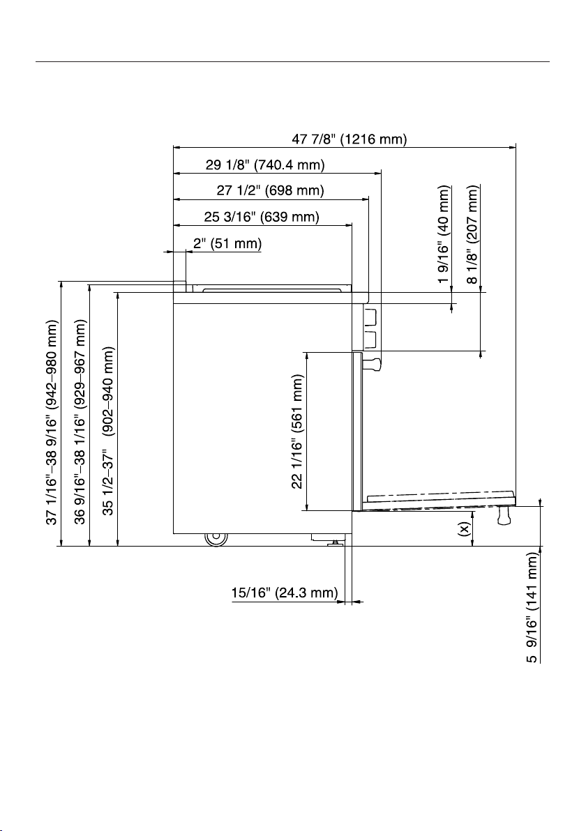
Dual Fuel Range dimensions
Detailed views of HR 1724
Side view of HR 1724
(x) = Depending on the appliance height adjustment: 5" - 6 1/2" (127 mm - 165.1
mm)
64
Page 65
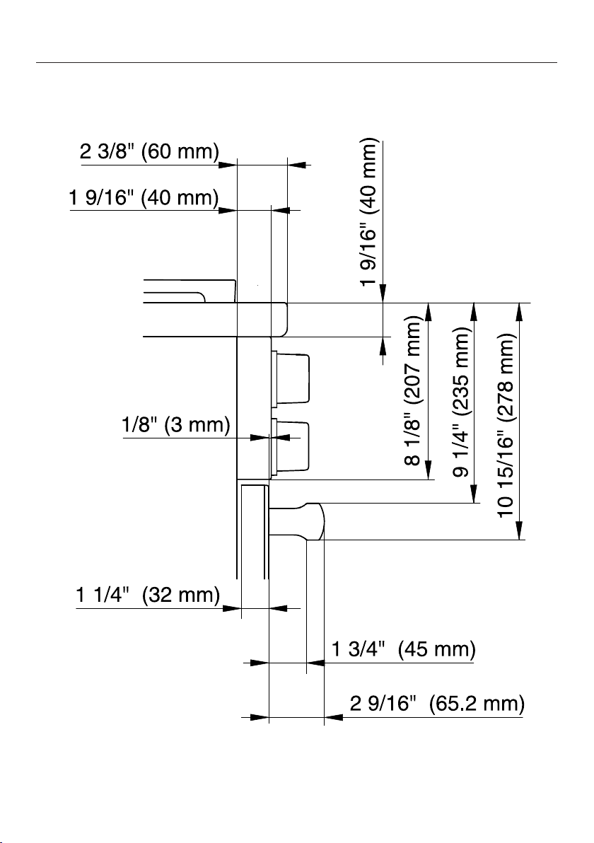
Detailed front side view of HR 1724
Dual Fuel Range dimensions
65
Page 66
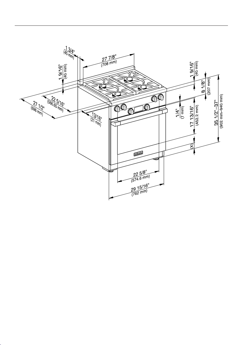
Dual Fuel Range dimensions
Front side view of HR 1724
(x) = Depending on the appliance height adjustment: 5" - 6 1/2" (127 mm - 165.1
mm)
66
Page 67
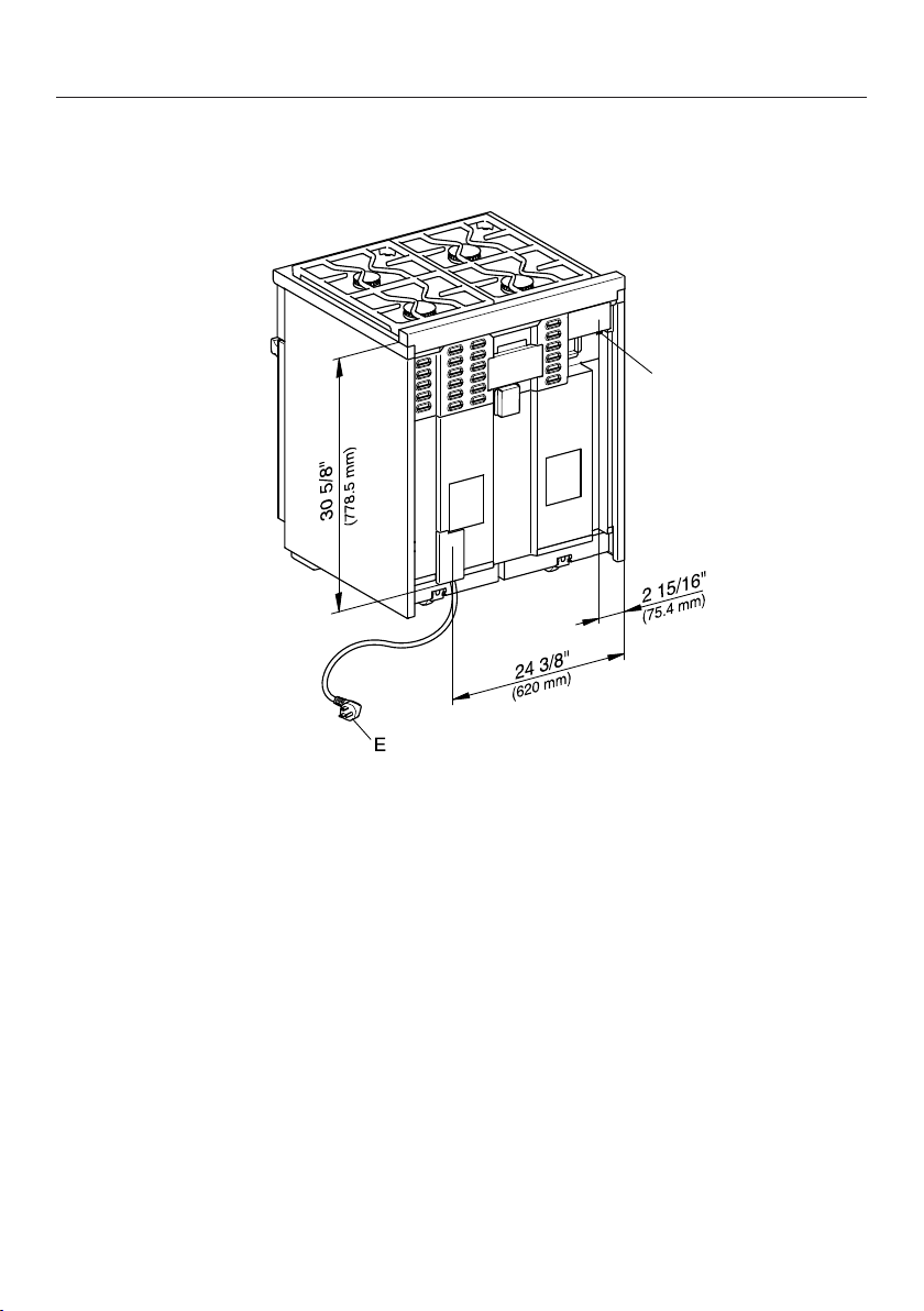
Rear view of HR 1724
G
Dual Fuel Range dimensions
E = Electrical connection
G = Gas connection
67
Page 68
Dual Fuel Range dimensions
Detailed views of HR 1924-2
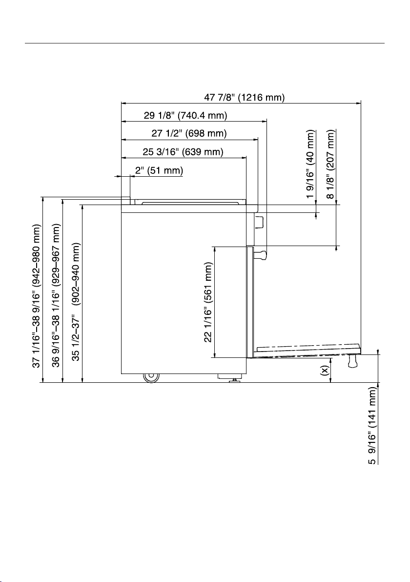
Side view of HR 1924-2
(x) = Depending on the appliance height adjustment: 5" - 6 1/2" (127mm -
165.1mm)
68
Page 69
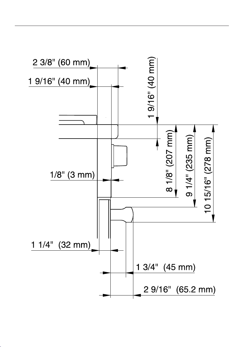
Detailed front side view of HR 1924-2
Dual Fuel Range dimensions
69
Page 70
Dual Fuel Range dimensions
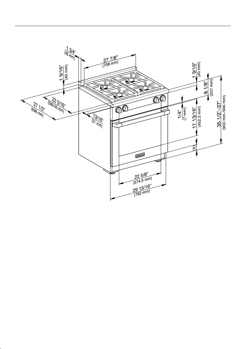
Front view of HR 1924-2
(x) = Depending on the appliance height adjustment: 5" - 6 1/2" (127mm -
165.1mm)
70
Page 71
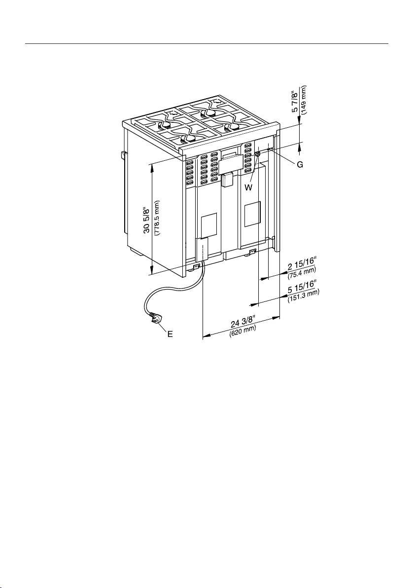
Rear view of HR 1924-2
Dual Fuel Range dimensions
E = Electrical connection
W = Water connection
G = Gas connection
71
Page 72
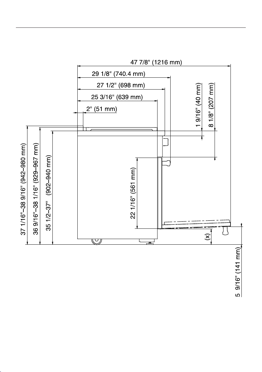
Dual Fuel Range dimensions
Detailed views of HR 1934-2
Side view of HR 1934-2
(x) = Depending on the appliance height adjustment: 5" - 61/2" (127mm -
165.1mm)
72
Page 73
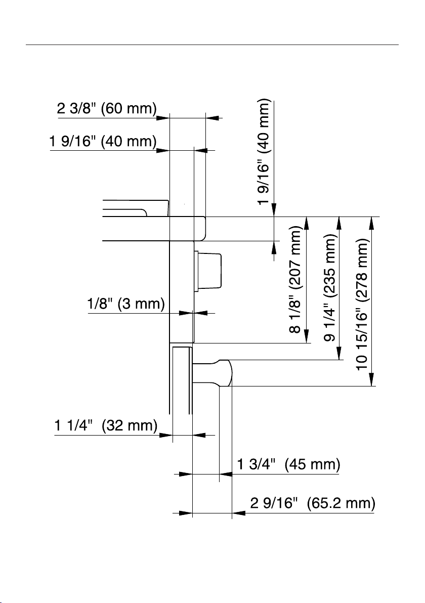
Detailed front side view of HR 1934-2
Dual Fuel Range dimensions
73
Page 74
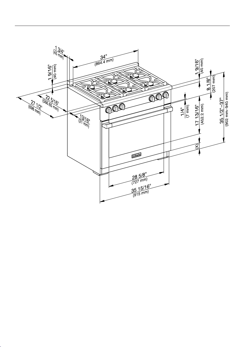
Dual Fuel Range dimensions
Front view of HR 1934-2
(x) = Depending on the appliance height adjustment: 5" - 61/2" (127mm -
165.1mm)
74
Page 75
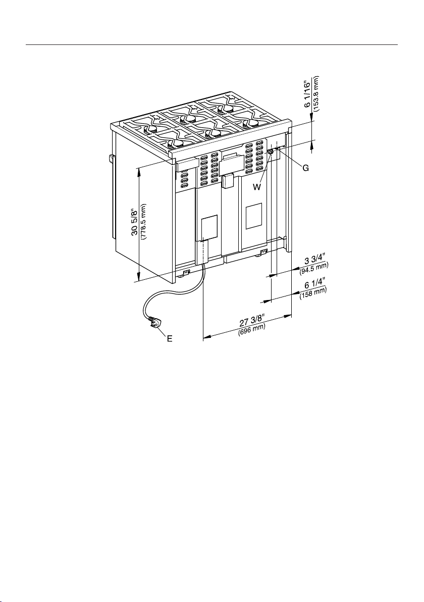
Rear view of HR 1934-2
Dual Fuel Range dimensions
E = Electrical connection
W = Water connection
G = Gas connection
75
Page 76
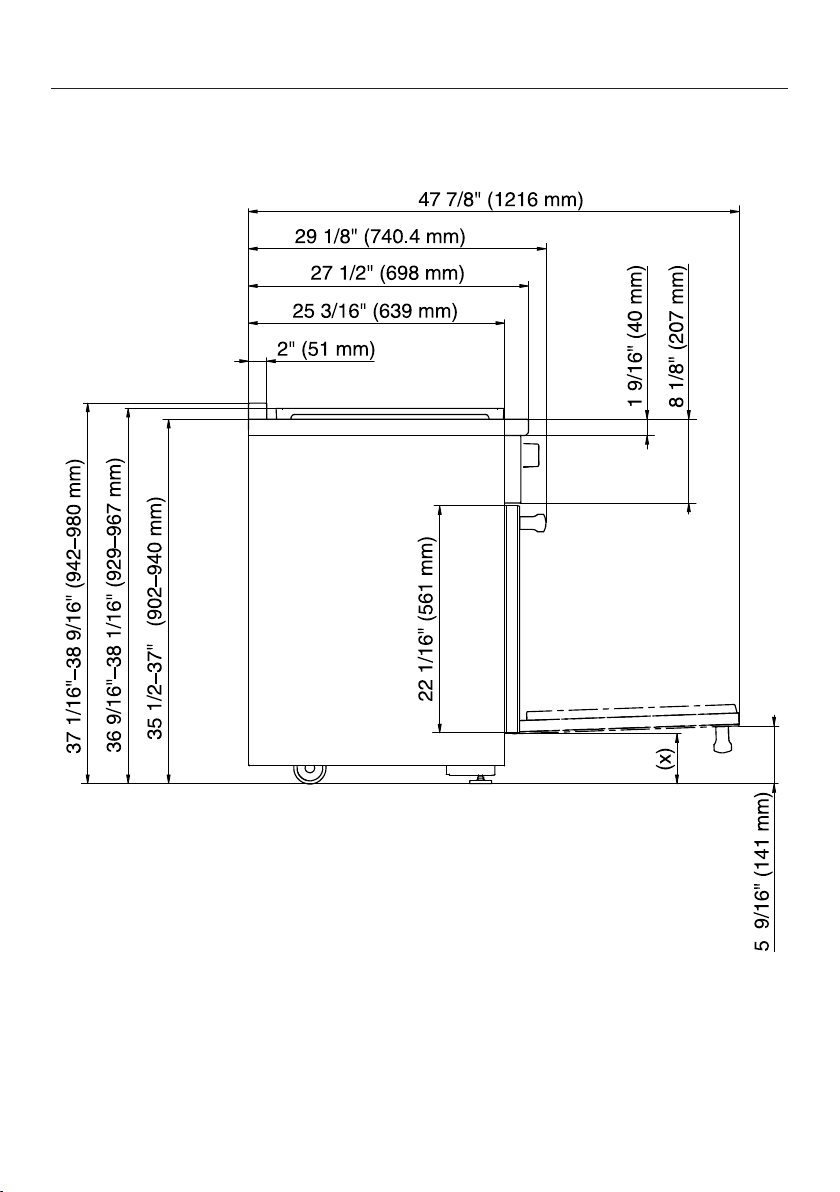
Dual Fuel Range dimensions
Detailed views of HR 1935-2
Side view of HR 1935-2
(x) = Depending on the appliance height adjustment: 5" - 61/2" (127mm -
165.1mm)
76
Page 77
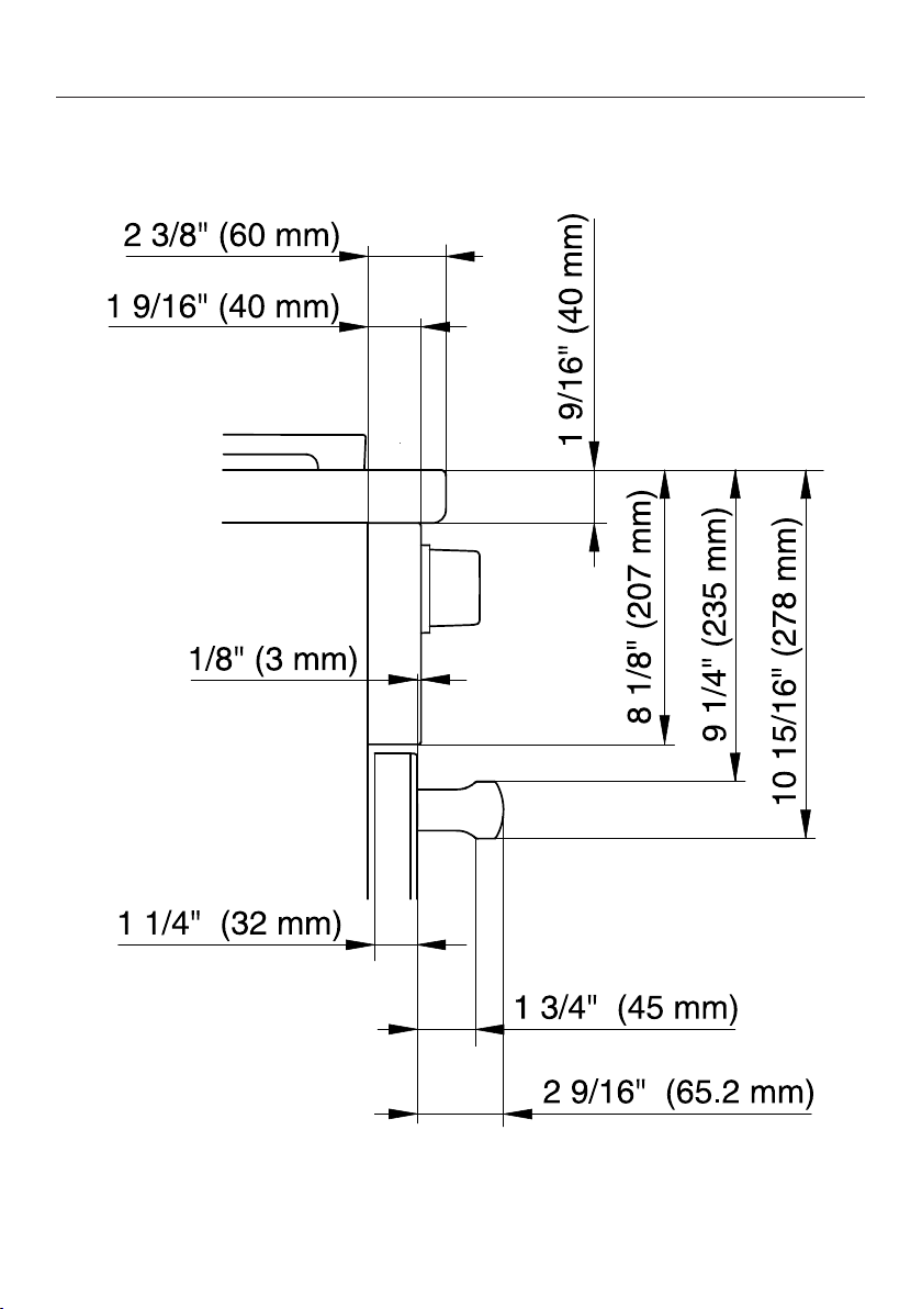
Detailed front side view of HR 1935-2
Dual Fuel Range dimensions
77
Page 78
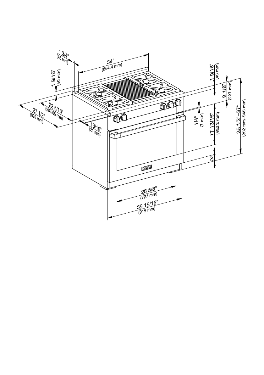
Dual Fuel Range dimensions
Front view of HR 1935-2
(x) = Depending on the appliance height adjustment: 5" - 61/2" (127mm -
165.1mm)
78
Page 79
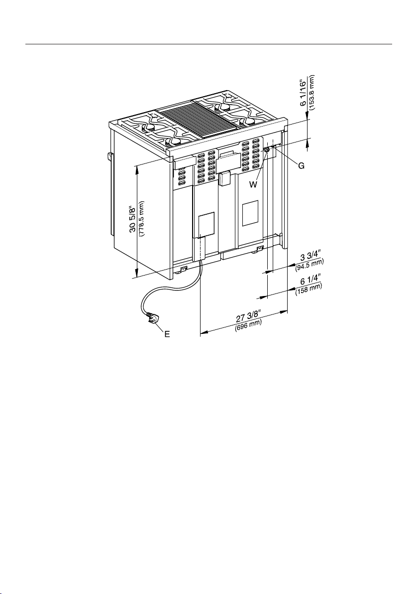
Rear view of HR 1935-2
Dual Fuel Range dimensions
E = Electrical connection
W = Water connection
G = Gas connection
79
Page 80
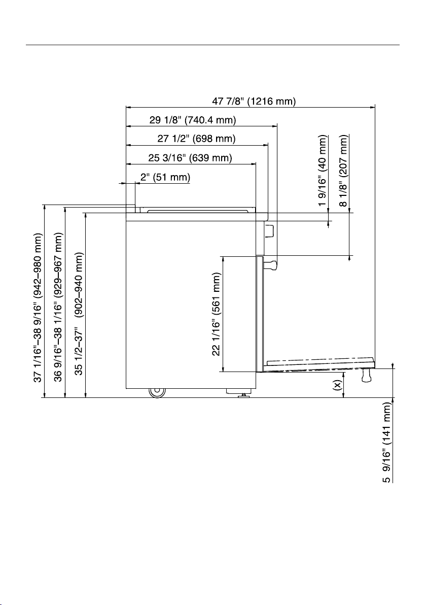
Dual Fuel Range dimensions
Detailed views of HR 1936-2
Side view of HR 1936-2
(x) = Depending on the appliance height adjustment: 5" - 61/2" (127mm -
165.1mm)
80
Page 81
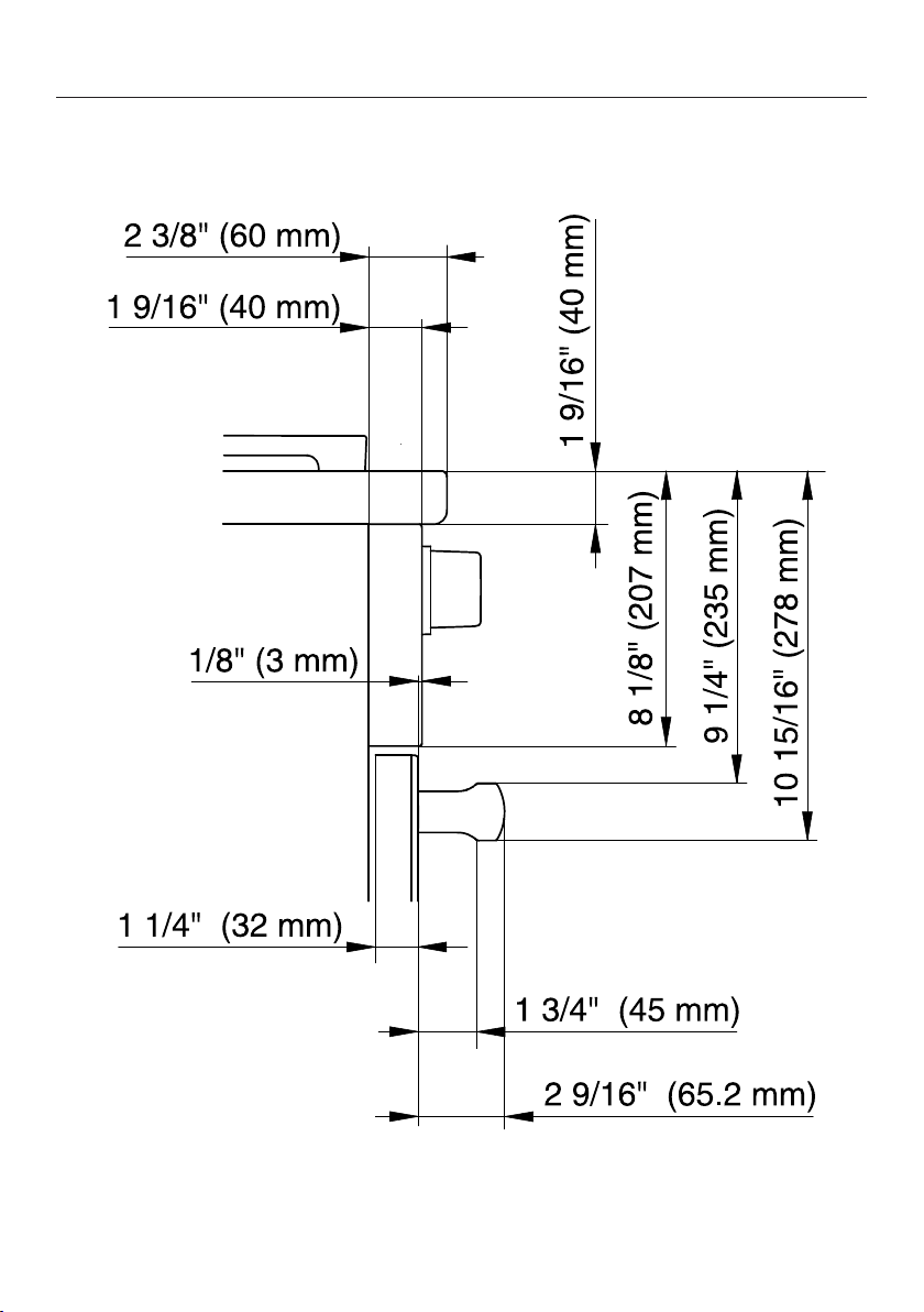
Detailed front side view of HR 1936-2
Dual Fuel Range dimensions
81
Page 82
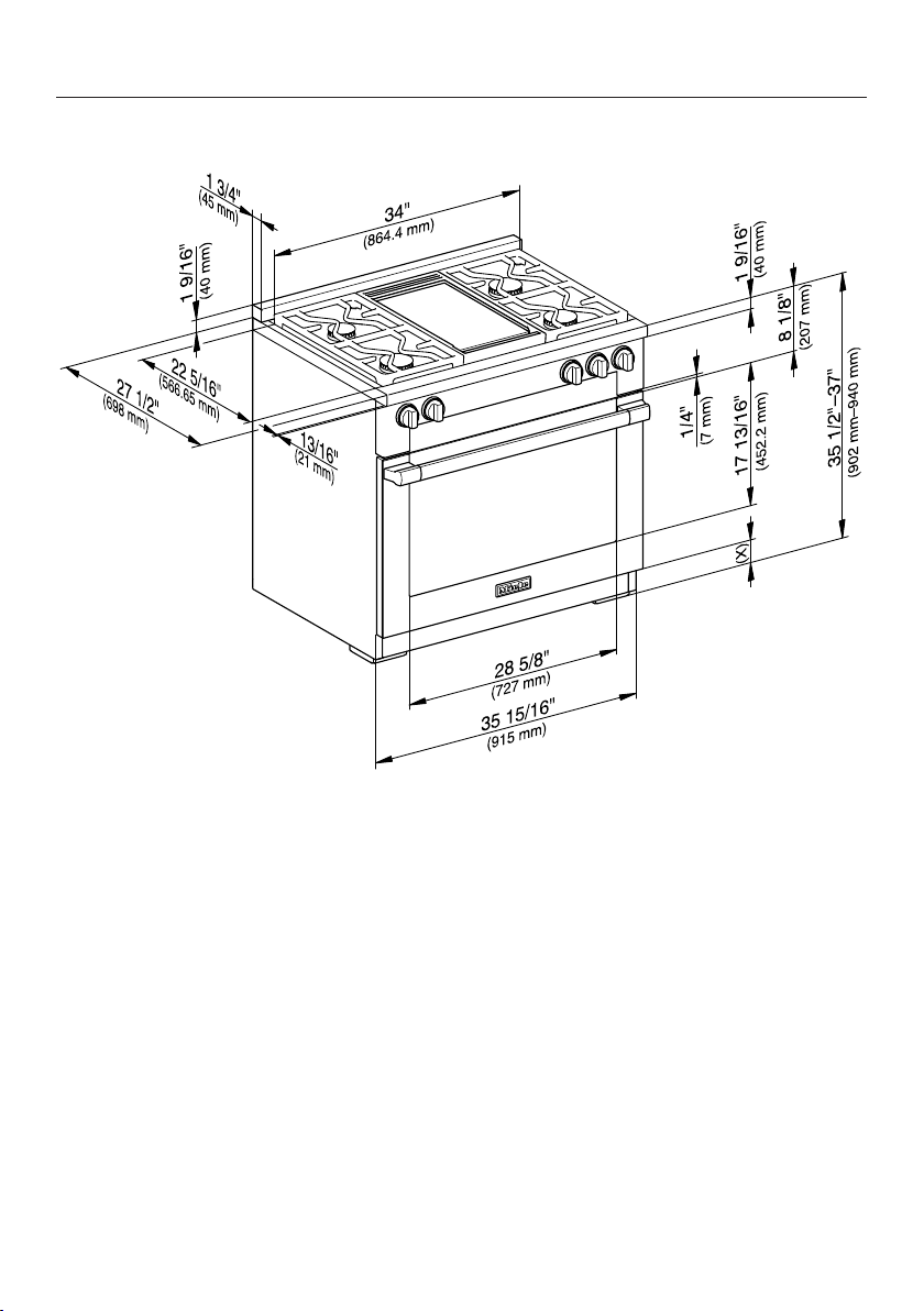
Dual Fuel Range dimensions
Front view of HR 1936-2
(x) = Depending on the appliance height adjustment: 5" - 61/2" (127mm -
165.1mm)
82
Page 83
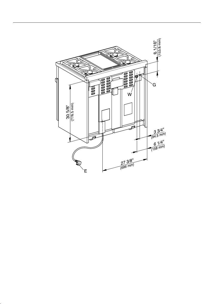
Rear view of HR 1936-2
Dual Fuel Range dimensions
E = Electrical connection
W = Water connection
G = Gas connection
83
Page 84
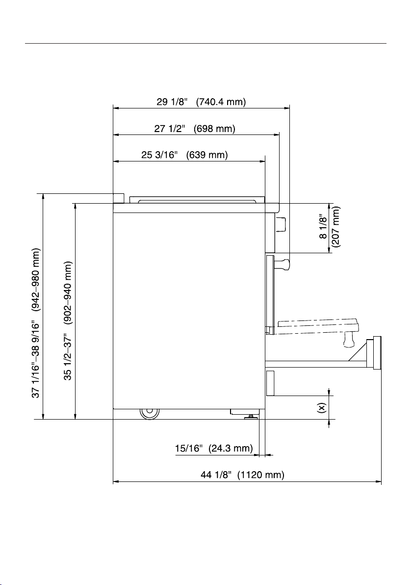
Dual Fuel Range dimensions
Detailed views of HR 1954-2
Side view of HR 1954-2
(x) = Depending on the appliance height adjustment: 4" - 51/2" (101.6mm -
139.7mm)
84
Page 85
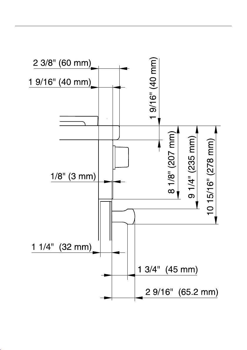
Detailed front side view of HR 1954-2
Dual Fuel Range dimensions
85
Page 86
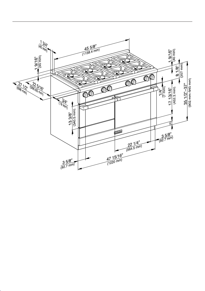
Dual Fuel Range dimensions
Front view of HR 1954-2
(x) = Depending on the appliance height adjustment: 4" - 51/2" (101.6mm -
139.7mm)
86
Page 87
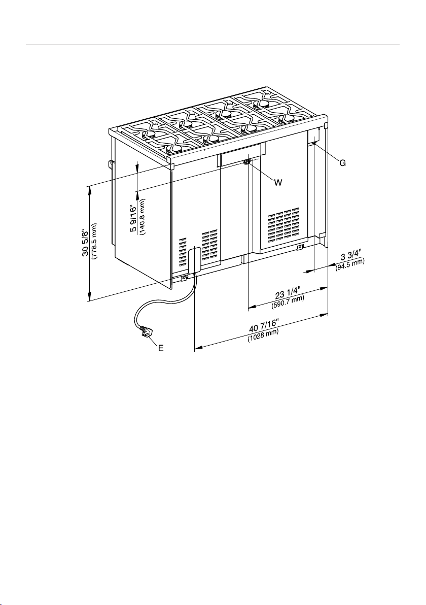
Rear view of HR 1954-2
Dual Fuel Range dimensions
E = Electrical connection
W = Water connection
G = Gas connection
87
Page 88
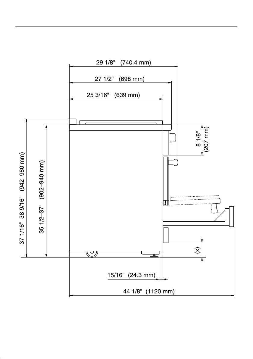
Dual Fuel Range dimensions
Detailed views of HR 1955-2
Side view of HR 1955-2
(x) = Depending on the appliance height adjustment: 4" - 51/2" (101.6mm -
139.7mm)
88
Page 89
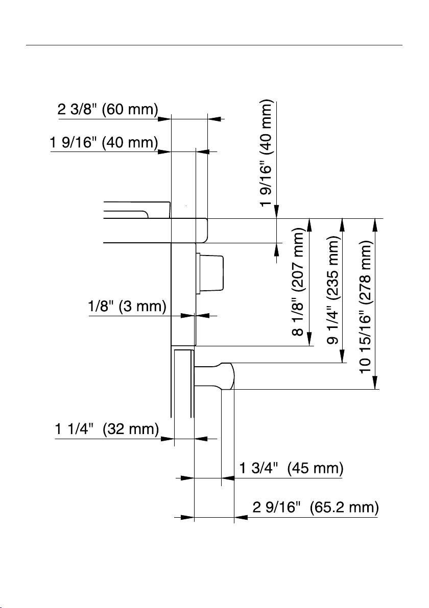
Detailed front side view of HR 1955-2
Dual Fuel Range dimensions
89
Page 90
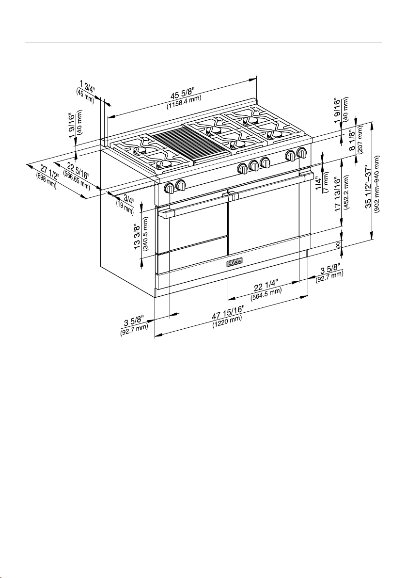
Dual Fuel Range dimensions
Front view of HR 1955-2
(x) = Depending on the appliance height adjustment: 4" - 51/2" (101.6mm -
139.7mm)
90
Page 91
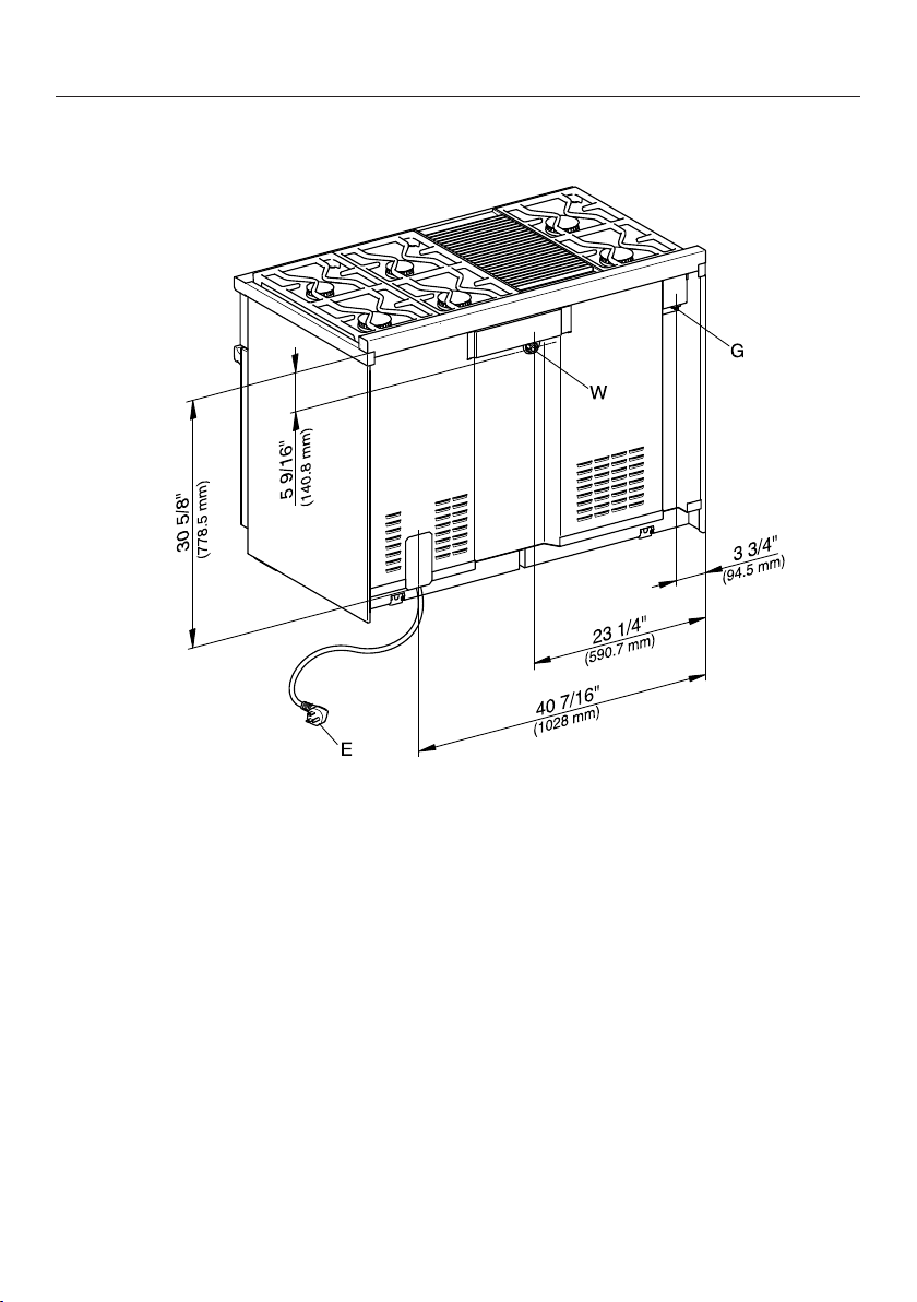
Rear view of HR 1955-2
Dual Fuel Range dimensions
E = Electrical connection
W = Water connection
G = Gas connection
91
Page 92
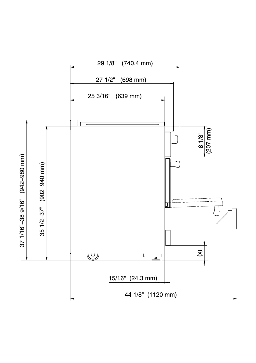
Dual Fuel Range dimensions
Detailed views of HR 1956-2
Side view of HR 1956-2
(x) = Depending on the appliance height adjustment: 4" - 51/2" (101.6mm -
139.7mm)
92
Page 93
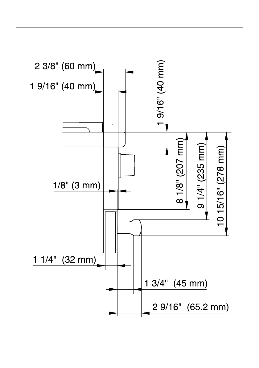
Detailed front side view of HR 1956-2
Dual Fuel Range dimensions
93
Page 94
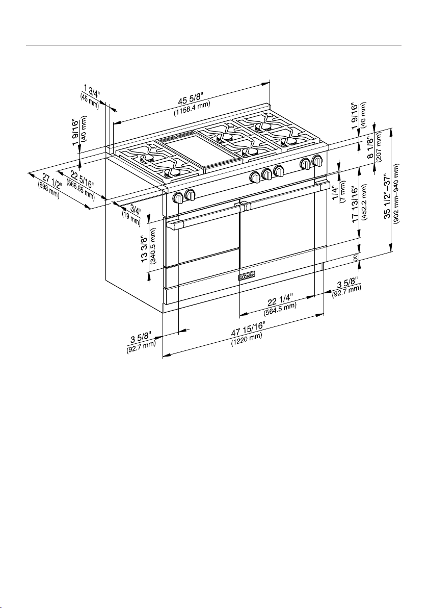
Dual Fuel Range dimensions
Front view of HR 1956-2
(x) = Depending on the appliance height adjustment: 4" - 51/2" (101.6mm -
139.7mm)
94
Page 95
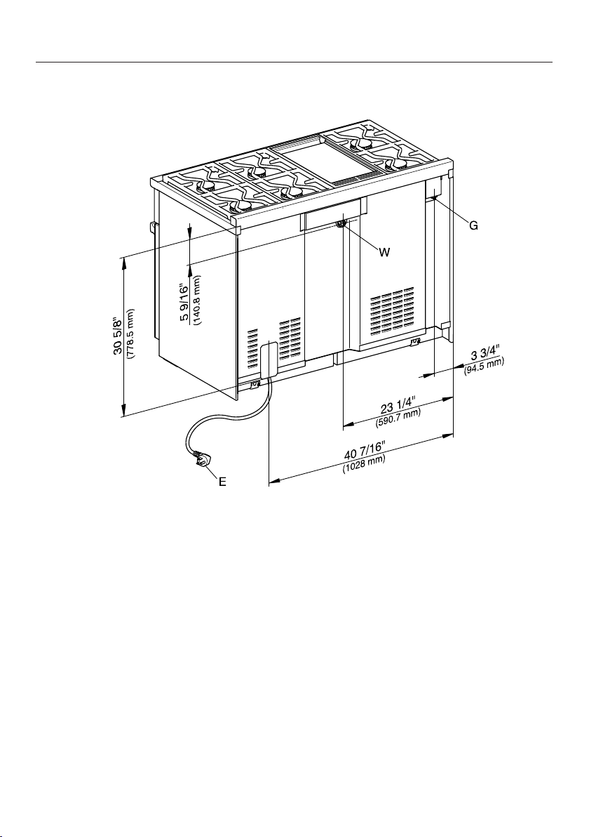
Rear view of HR 1956-2
Dual Fuel Range dimensions
E = Electrical connection
W = Water connection
G = Gas connection
95
Page 96
Anti-tip device
Before installation
WARNING
Children and adults can tip over the
range if has not been secured. This
may lead to fatal injuries.
Make sure that the anti-tip device is
properly installed and locked into
place. It should be screwed to the
floor or wall and engage with the
center of the bottom of the range.
You must take care to protect the
installed flooring when moving the
range.
After moving the range, make sure
that the anti-tip device locks back
into place. It should be screwed to
the floor or wall and engage with the
center of the bottom of the range.
Do not use the range if the anti-tip
device has not been properly
installed and engaged.
Due to the size and weight of the
appliance, installation should be
carried out by two people.
We recommend removing the oven
door before installing the range (see
“Removing the door” in the Operating
Instructions) and all accessories from
the oven interior. This will make it
easier to install the appliance in its
designated space.
Once the range has been installed and
secured against tipping, you can
reattach the oven door (see
“Reinstalling the door” in the
Operating Instructions).
Do not carry or lift the range by the
oven door handle or the control
panel!
Any opening in the wall behind the
appliance and in the floor under the
appliance shall be sealed.
96
Page 97
Anti-tip device
A
Checking the installation space
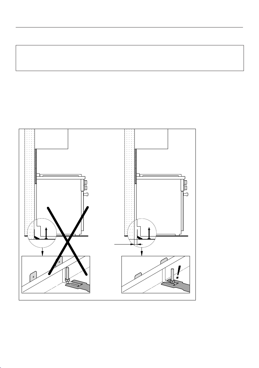
Install the anti-tip device on a floor capable of bearing significant weight, such as
a concrete floor, concrete wall or timber framing. The surface must be flat and
level.
If the rear of the range has distance A to the supporting wall due to unevenness
or wall covering (e.g., tile level), you must install the anti-tip device to the
supporting floor. Alternatively, you can also install the anti-tip device with an
adapter between the supporting wall and the anti-tip device. The adapter must
compensate dimension A and be made of suitable material so that a supporting
composite arises between the wall and anti-tip device. Use the corresponding
screws (length and diameter).
A = Distance between the rear of the range to the supporting wall
Check the floor surface.
Check the installation dimensions.
97
Page 98

Anti-tip device
Check the diagrams for the building's supply lines. Make sure that you do not
damage any lines when drilling the holes to attach the anti-tip device.
Check the position of the electric, gas and water connections (see “Electrical
connection,” “Gas connection” and “Plumbing”). An overview on the electrical
connections for your range can be found in “Notes on installation”.
98
Page 99
Anti-tip device
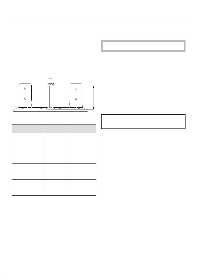
X
Included accessories
- 1 anti-tip device
- 4 screws
- 4 plugs
Installation dimensions of locking bolt
Anti-tip device, front view
Model Width Yes
HR 1421
HR 1622-2
HR 112x
HR 1724
HR 192x-2
2915/16"
(762mm)
313/16"
(97mm)
Installing the range with the anti-tip device
Wear safety shoes and gloves.
The anti-tip device should be installed
at the bottom rear of the range at the
midpoint of the width.
Measure the installation space for the
range close to floor level.
Mark the wall at the middle of the
space width.
Position the notch of the anti-tip
device on the wall marking.
The anti-tip device must fit tightly on
the floor or the wall.
HR 113x-1
HR 193x-2
HR 195x-2 4715/16"
3515/16"
(915mm)
(1220mm)
313/16"
97mm
31/4"
82mm
99
Page 100
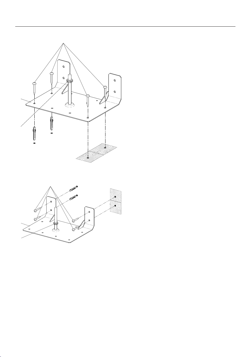
Anti-tip device
1
3
2
1
2
3
Attaching to the floor
Screw the locking nut to the bolt,
see the “Installation dimensions of
locking bolt” table.
Attaching to the wall
a
Anti-tip device
b
Screws
c
Locking nut
Secure the anti-tip device to the
100
floor surface with suitable bearing
capacity, either to the floor or wall.
using four screws .
 Loading...