

Page 1
Installation instructions
for dishwashers
To prevent accidents and
reduce machine damage, read
the Operating instructions
before installing or using
the machine. M.-Nr. 05 255 670
ö]
Page 2

These installation instructions apply to several different dishwasher models.
The model designations used in these instructions always refer to the model
listed on the data plate, regardless of the designation on the control panel.
The data plate is on the upper edge of the dishwasher door.
The model designations only use the model number, e. g. the G 640 SCi dish
washer is designated G 640.
-
Always read the “Warning and safety instructions” in the operations manual be
fore installing the dishwasher.
2
-
Page 3

Contents
Contents
Installation . . . . . . . . . . . . . . . . . . . . . . . . . . . . . . . . . . . . . . . . . . . . . . . . . . . . . . . 4
1. Installing the steam deflector (if applicable). . . . . . . . . . . . . . . . . . . . . . . . . . . . 7
2. Installing the dishwasher under the countertop. . . . . . . . . . . . . . . . . . . . . . . . . . 7
Installing the slides . . . . . . . . . . . . . . . . . . . . . . . . . . . . . . . . . . . . . . . . . . . . . . . 8
Mounting brackets . . . . . . . . . . . . . . . . . . . . . . . . . . . . . . . . . . . . . . . . . . . . . . . 8
Leveling legs. . . . . . . . . . . . . . . . . . . . . . . . . . . . . . . . . . . . . . . . . . . . . . . . . . . . 9
3. Installing the control panel. . . . . . . . . . . . . . . . . . . . . . . . . . . . . . . . . . . . . . . . . 10
4. Aligning the control panel with the drawer fronts. . . . . . . . . . . . . . . . . . . . . . . . 12
5. Installing the custom door panel. . . . . . . . . . . . . . . . . . . . . . . . . . . . . . . . . . . . 13
6. Securing the dishwasher to the countertop. . . . . . . . . . . . . . . . . . . . . . . . . . . . 17
7. Adjusting the door springs. . . . . . . . . . . . . . . . . . . . . . . . . . . . . . . . . . . . . . . . . 18
8. Installing the toekick. . . . . . . . . . . . . . . . . . . . . . . . . . . . . . . . . . . . . . . . . . . . . . 19
Electrical connection. . . . . . . . . . . . . . . . . . . . . . . . . . . . . . . . . . . . . . . . . . . . . . 22
Plumbing. . . . . . . . . . . . . . . . . . . . . . . . . . . . . . . . . . . . . . . . . . . . . . . . . . . . . . . . 24
Accessories . . . . . . . . . . . . . . . . . . . . . . . . . . . . . . . . . . . . . . . . . . . . . . . . . . . . . 28
Technical Data . . . . . . . . . . . . . . . . . . . . . . . . . . . . . . . . . . . . . . . . . . . . . . . . . . . 29
3
Page 4
Installation
Installation
Integrated (“i”) dishwashers
“i” models are designed for installation
under a continuous countertop.
The control panel with accessories is
–
enclosed in a separate package for
on site installation.
The front is designed for a custom
–
made panel to match the existing
kitchen cabinets.
All instructions necessary for installing
the dishwasher are described in the fol
lowing text.
“i” models can be converted into a
built-under model (“U”).
The dishwasher is converted using a
–
GDU kit (decor set).
The decor set includes a toekick
–
panel. The height of the dishwasher
toekick can be adjusted to match
that of adjacent cabinets. The
toekick recess depth is also adjust
able.
Instructions for installing the decor set
are given in a separate pamphlet that is
included with the decor set.
To ensure stability, these dishwashers should only be installed under a
continuous countertop and securely
fastened to the cabinet base units.
-
The dishwasher should not be installed underneath a cooktop. The
radiant heat generated by the cook
top may damage the dishwasher.
4
Page 5
Installation
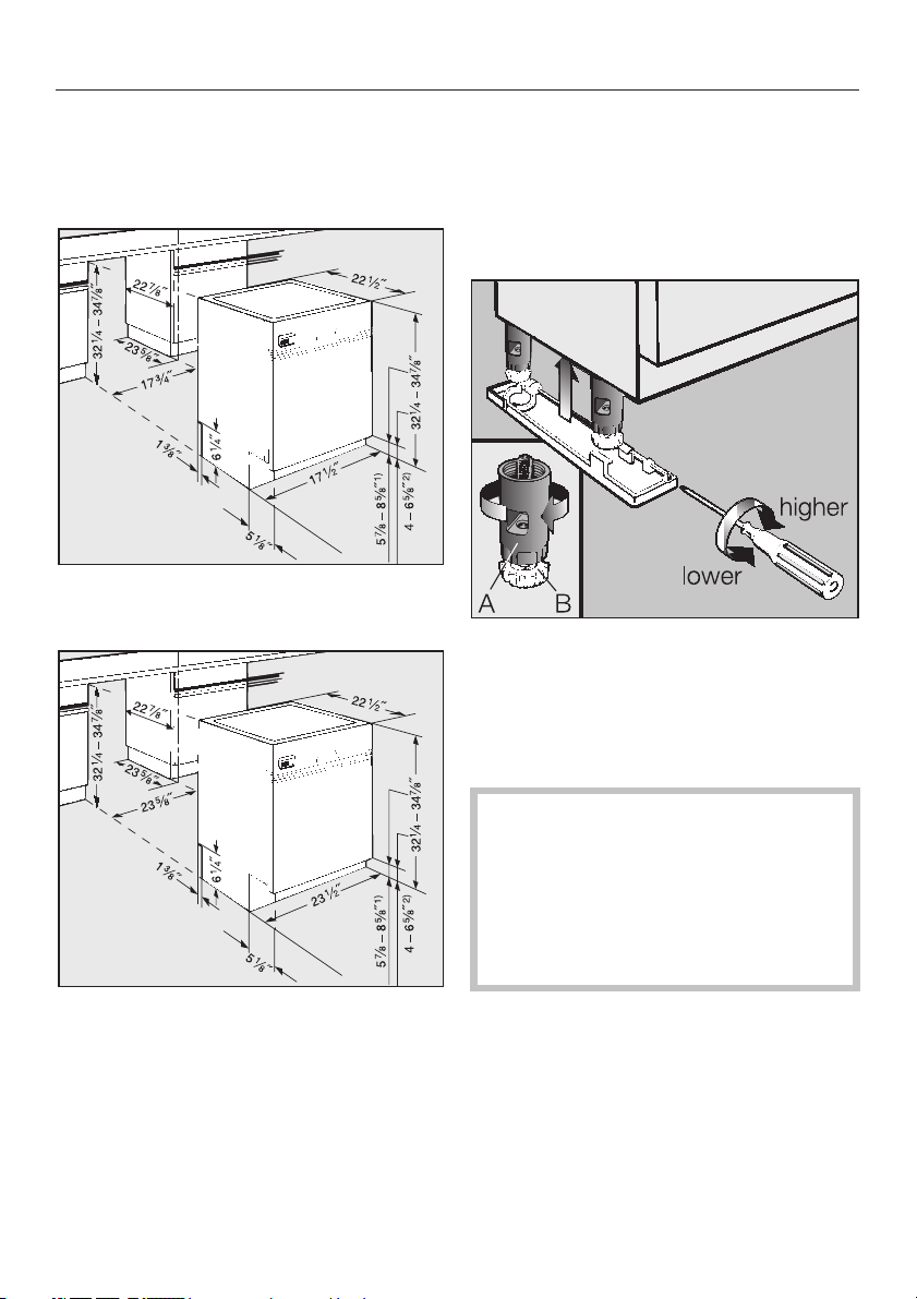
Dimensions
Dishwasher models G 601 - G 624
Dishwasher models G 640 - G 691
Removing the leg extensions
The black leg extensions can be re
moved to reduce the height of the ma
chine to 32 1/4" – 33" (819-838 mm)
(see Inset).
A = Black leg extension (removable)
B = White leg (must be installed on
machine).
^ After removing the extension, screw
the white legs onto the dishwasher.
-
-
1) with 34 7/8" (870 mm) machine
height
2) with 32 1/4" (820 mm) machine
height
Range of adjustment is approximately
2 3/4" (7 cm).
Machine heights of 33 1/4" – 34"
(845-864 mm) cannot be obtained
using the supplied legs.
For this height range, or for heights
greater than 34 7/8" (886 mm), con
tact the Miele Technical Service De
partment for the appropriate legs.
-
-
5
Page 6
Installation
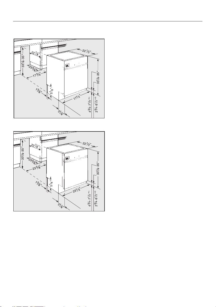
Dishwasher models G 801 - G 824
Dishwasher models G 840 - G 891
1) with 35" (890 mm) machine height
2) with 33 1/8" (840 mm) machine height
Range of adjustment is approximately
2" (5 cm).
Machine heights between 35" and 37"
can be obtained if the supplied legs are
removed and extended legs are at
tached. Please contact the Miele Tech
-
nical Service Department for the appro
priate legs.
6
-
Page 7
Installation
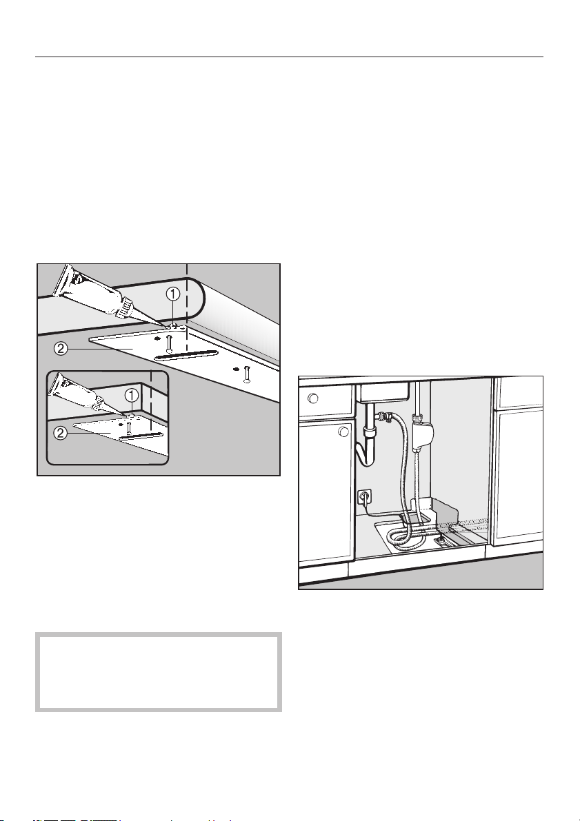
1.Installing the steam deflector
(if applicable)
A stainless steel coverplate is supplied
to protect the underside of the
countertop against steam rising from
the dishwasher when the door is
opened. If the countertop is made of
Corian®, granite, marble or other solid,
waterproof material, the steam deflector
should not be used.
2.Installing the dishwasher
under the countertop
For ease of service and quick discon
nection, it is best to install the machine
so that the water and electricity sup
plies can be accessed through an adja
cent cabinet, rather than situating them
behind the machine. If the electrical
and water supplies are located behind
the machine the dishwasher will have to
be removed from the cabinet for ser
vice. See the “Plumbing” and “Electri
cal” sections for proper connection pro
cedures before continuing. If electrical
and water supplies are not located in
adjacent cabinetry it is extremly important that the toekick is removable.
-
-
-
-
-
-
^ Squeeze a bead of sealant from the
supplied tube into the angle formed
by the curved edge
coverplate.
^
Align the plate
edge of the worktop (see illustration)
and use the supplied tacks to nail it
in place.
On countertops with wood or lami
nate edging, the tacks should be
nailed through the rear holes of the
coverplate.
b of the
c with the lower front
-
7
Page 8
Installation
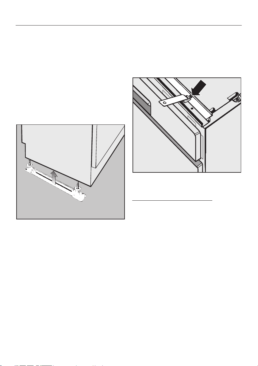
Installing the slides
Two slides are included and should be
installed on the feet of the dishwasher
before the machine is pushed under
the countertop. This will allow the ma
chine to slide easier, protect the floor,
and allow adjustment of the rear level
ing legs from the front of the machine.
Adjust the height of the legs so that
^
the top of the dishwasher is roughly
1/4" (5 mm) below the countertop.
^
Place the slides, with the ratchet at
the rear, under the dishwasher legs.
Mounting brackets
To ensure stability this dishwasher
should be securely attached to the
countertop (step 6). Two mounting
brackets are included for this purpose.
-
-
^ Insert the tab of each bracket into
the guide holes on the top.
Stone or marble countertops:
For these countertops the dishwasher
must be secured to the adjacent cabinets. Special brackets must be used,
see “Accessories”.
The drain hose connection at the rear of
the dishwasher can be turned to allow
the hose to be angled to the right or
left.
8
Page 9
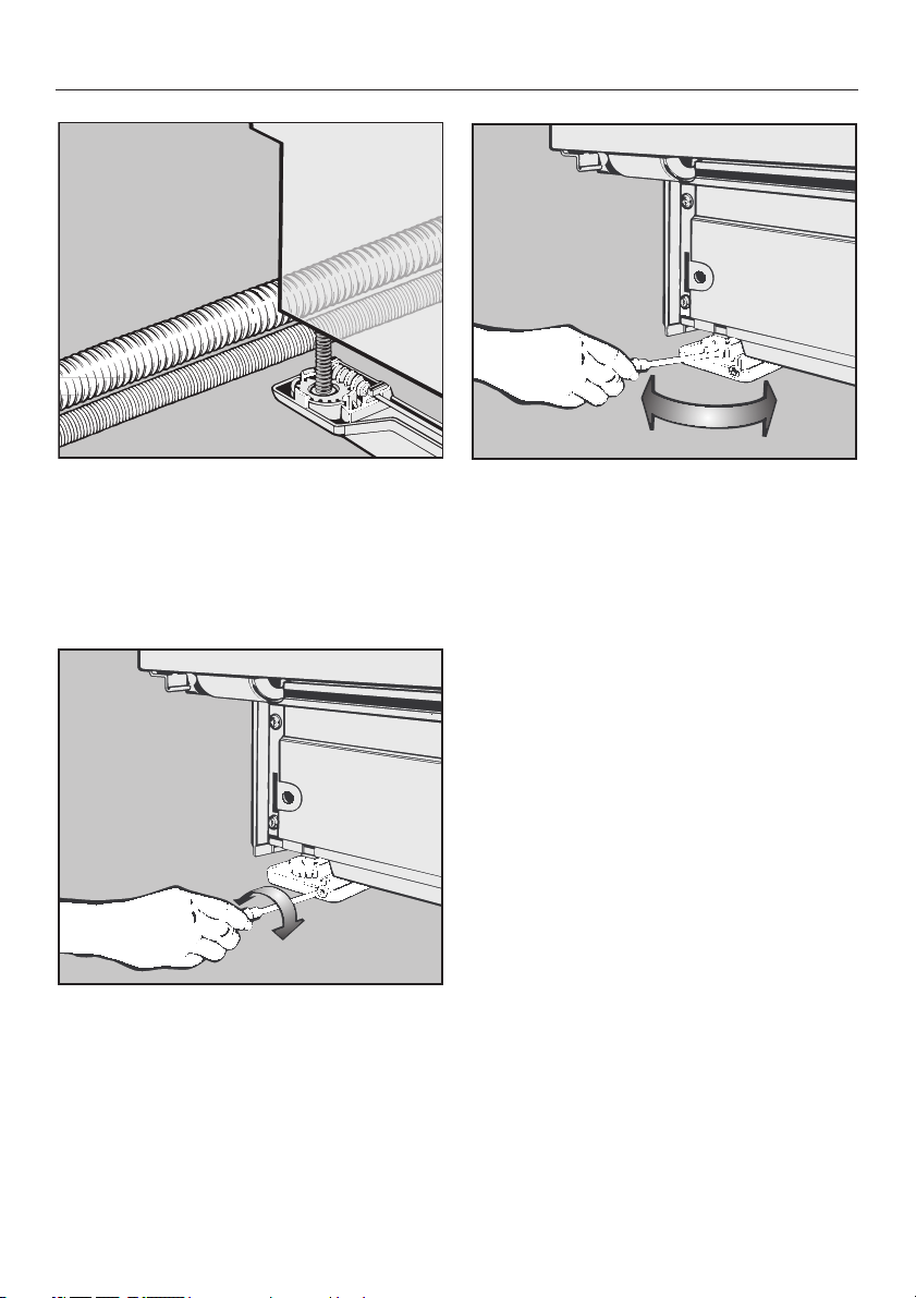
Push the machine into the opening,
^
making sure the electrical cable and
hoses can reach their connection
points without kinks.
Leveling legs
Installation
Adjust the front leveling legs by
^
pushing on the feet with a slotted
screwdriver.
^ Tipping the machine slightly to the
rear, if possible, will make adjusting
the front legs easier. Make sure the
machine is level when adjustments
are complete.
^
Adjust the rear leveling legs to the re
quired height with a T20 Torx screw
driver.
To raise the machine - turn clockwise.
To lower the machine -turn counter
clockwise.
Several turns may be needed to set the
correct height. A low speed electric or
cordless screwdriver can also be used.
The dishwasher should be raised until it
just touches the underside of the
countertop.
-
-
9
Page 10
Installation
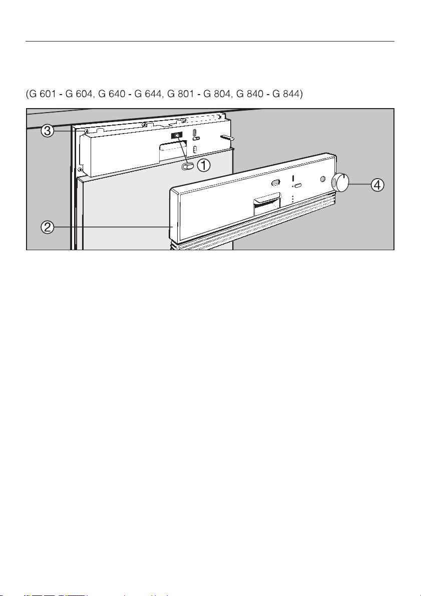
3. Installing the control panel
Dishwashers with selector knobs
^ Place the cover
ton.
^ Position the control panel
backing plate and fasten it from the
inside of the door
screws provided.
b over the push but-
c over the
d using the six
^ Align and press the knob onto its
e.
shaft
10
Page 11
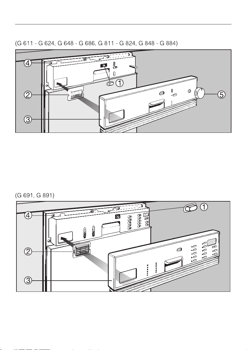
Dishwashers with selector knobs and ventilation grills
Installation
^ Place the cover
ton.
^ Push the ventilation grill
metal backing plate.
Dishwashers without selector knobs
^
Place the cover
ton.
^
Push the ventilation grill
metal backing plate.
b over the push but-
c into the
b over the push but
c into the
^ Position the control panel
backing plate and fasten it from the
inside of the door
screws provided.
^ Align and press the knob onto its
shaft
f.
^
-
Position the control panel
backing plate and fasten it from the
inside of the door
screws provided.
e using the six
e using the six
d over the
d over the
11
Page 12
Installation
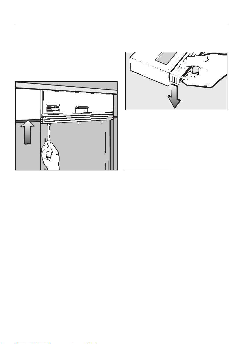
4.Aligning the control panel
with the drawer fronts
The control panel can be aligned
^
with the drawer fronts of the kitchen
cabinets by adjusting the spacer
bars.
^ Using an 8 mm socket, turn the nut
clockwise or counterclockwise until
the spacers reach the required
height.
If necessary, individual (or all) spacer
bars can be removed.
To remove the spacer bars from the
^
control panel, place the panel on a
table, printed side up, and gently
push down on the spacer bars at a
point near the bottom of the control
panel. This will release the mounting
bolts from their slots.
Adjustment range
from 4 1/2" control panel with(112 mm): out spacer bars,
to 5 3/4" control panel with
(145 mm): four spacer bars,
12
to 6" using a fifth spacer bar
(154 mm): (optional accessory).
^
After adjusting the control panel
height, cut off the plastic screw ex
cess.
-
Page 13
Installation
5.Installing the custom
door panel
A custom door panel matching the
kitchen cabinetry can be installed on
the dishwasher by using the provided
templates and bracket.
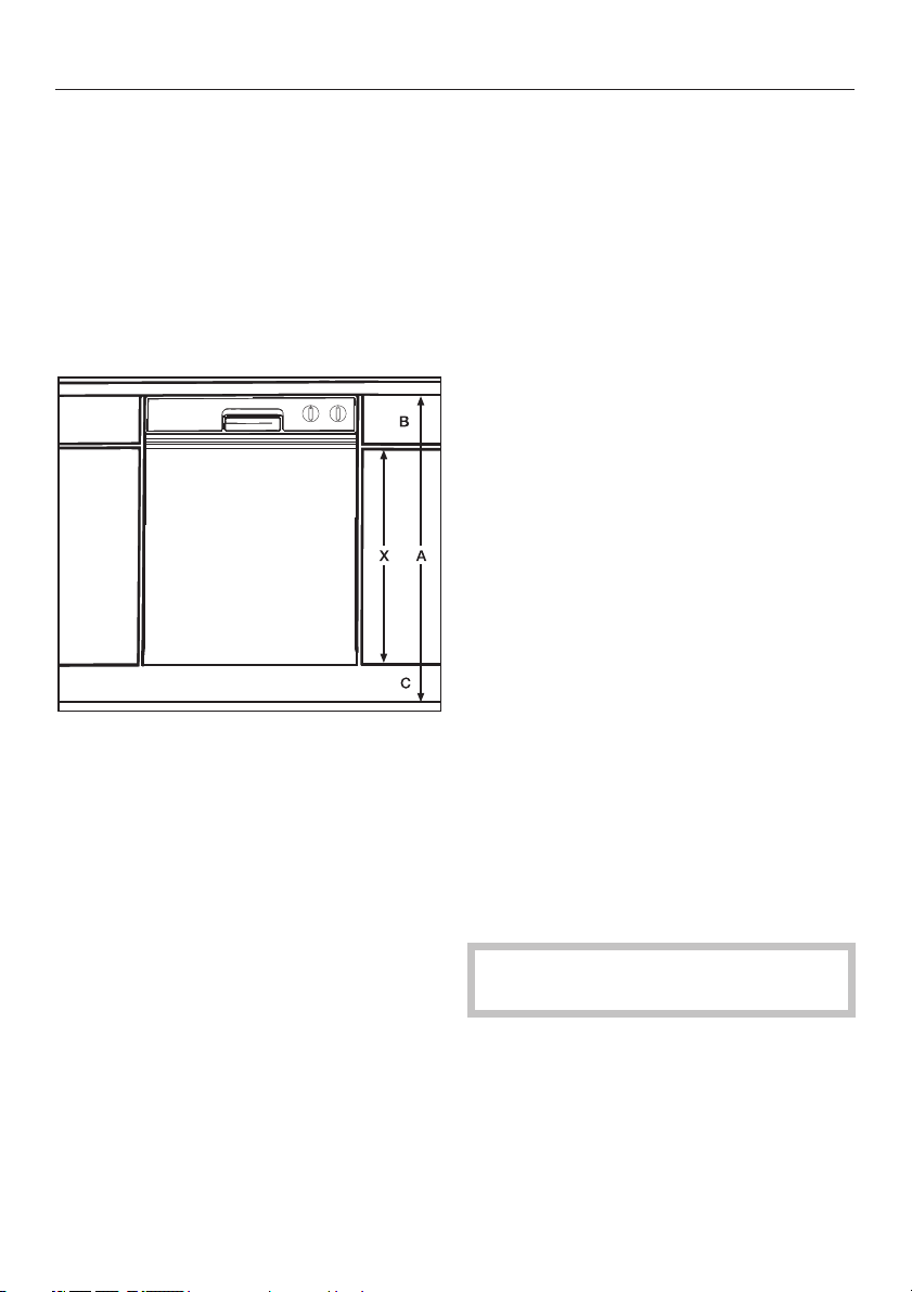
Panel size is determined in the follow
ing manner:
Length:
Determined using the following calculation: X = A – B – C
X =Panel length
A =Height to the underside of the
countertop
B =Control Panel Height (Note 1)
C =Toe Kick Height
-
As long as the panel length calculated
is within the Range of Panel Sizes listed
below, the custom panel should fit with
out a problem.
Range of Panel Sizes
G 601 - G 624
Length: 19" - 23 3/4" (48.3 - 60.3 cm)
Width: 17 1/2" (44.8 cm)
G 640 - G 691
Length: 19" - 23 3/4" (48.3 - 60.3 cm)
Width: 23 1/2" (59.8 cm)
G 801 - G 824
Length: 21" - 25 3/4" (53.3 - 65.4 cm)
Width: 17 1/2" (44.8 cm)
G 840 - G 891
Length: 21" - 25 3/4" (53.3 - 65.4 cm)
Width: 23 1/2" (59.8 cm)
Note: The maximum panel length is
only applicable when no spacer bars
are used.
If a stainless steel panel is being used,
please follow the separate installation
instructions included with the panel.
-
Note 1: Control Panel Height is deter
mined by the height of the drawers in
the cabinets. This height is adjustable
between 4 ½” and 5 ¾” with spacer
bars provided. Additional spacer bars
and foam inserts may be ordered to
reach 6” in height.
-
After panel installation, see Step 7
“Adjusting the door springs”.
13
Page 14
Installation
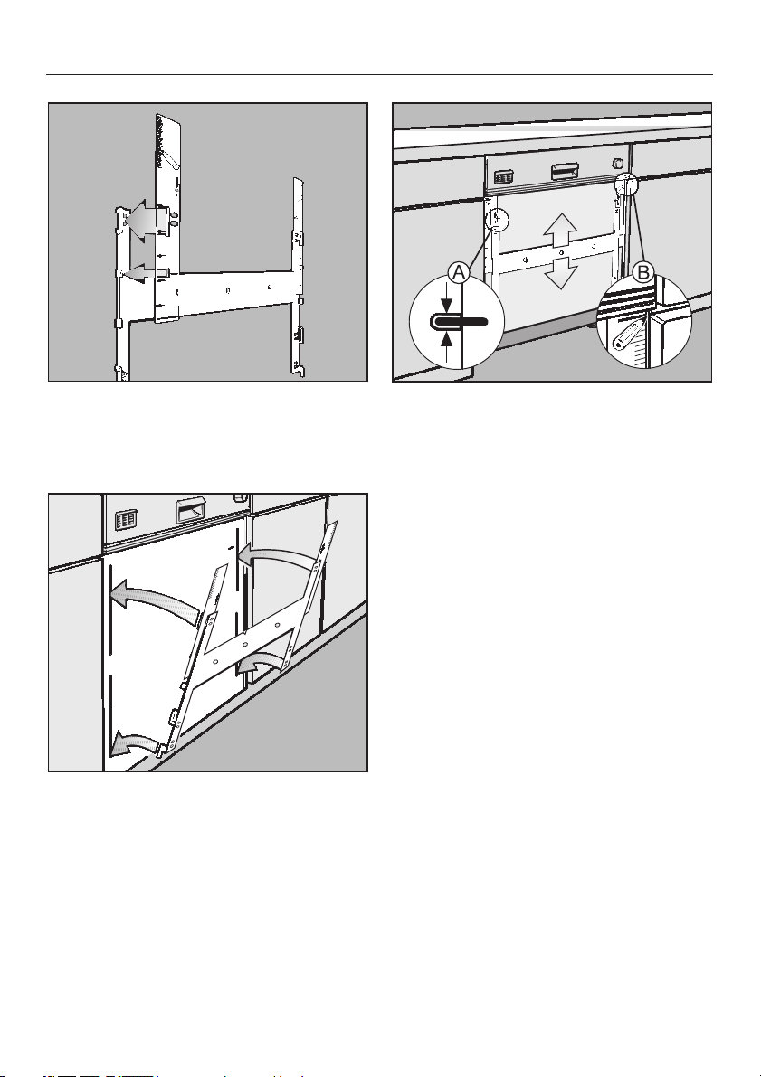
Place a template on each end of the
^
bracket as shown, making sure the
rule marks face the outside of the
bracket.
Slide the mounting bracket up or
^
down until the oblong holes on the
machine door align with the corresponding marks on the template (as
shown in the left side of inset
^ Draw a line on each template that is
even with the top edge of the adjacent cabinet door (inset
D).
E).
^
Hang the bracket on the machine
door.
^
Slide the top edge of the templates
under the spacer bars and control
panel.
14
^ Remove the bracket from the door.
^ Place the door panel on a flat sur-
face, good side facing down, taking
care not to scratch the surface. Make
certain that the bottom of the panel is
closest to you.
^
Place the bracket on the back of the
door panel and adjust it so that:
–
the lines drawn on the templates
align with the upper edge of the door
panel and;
–
the mounting bracket is centered (left
to right) on the door panel.
Page 15
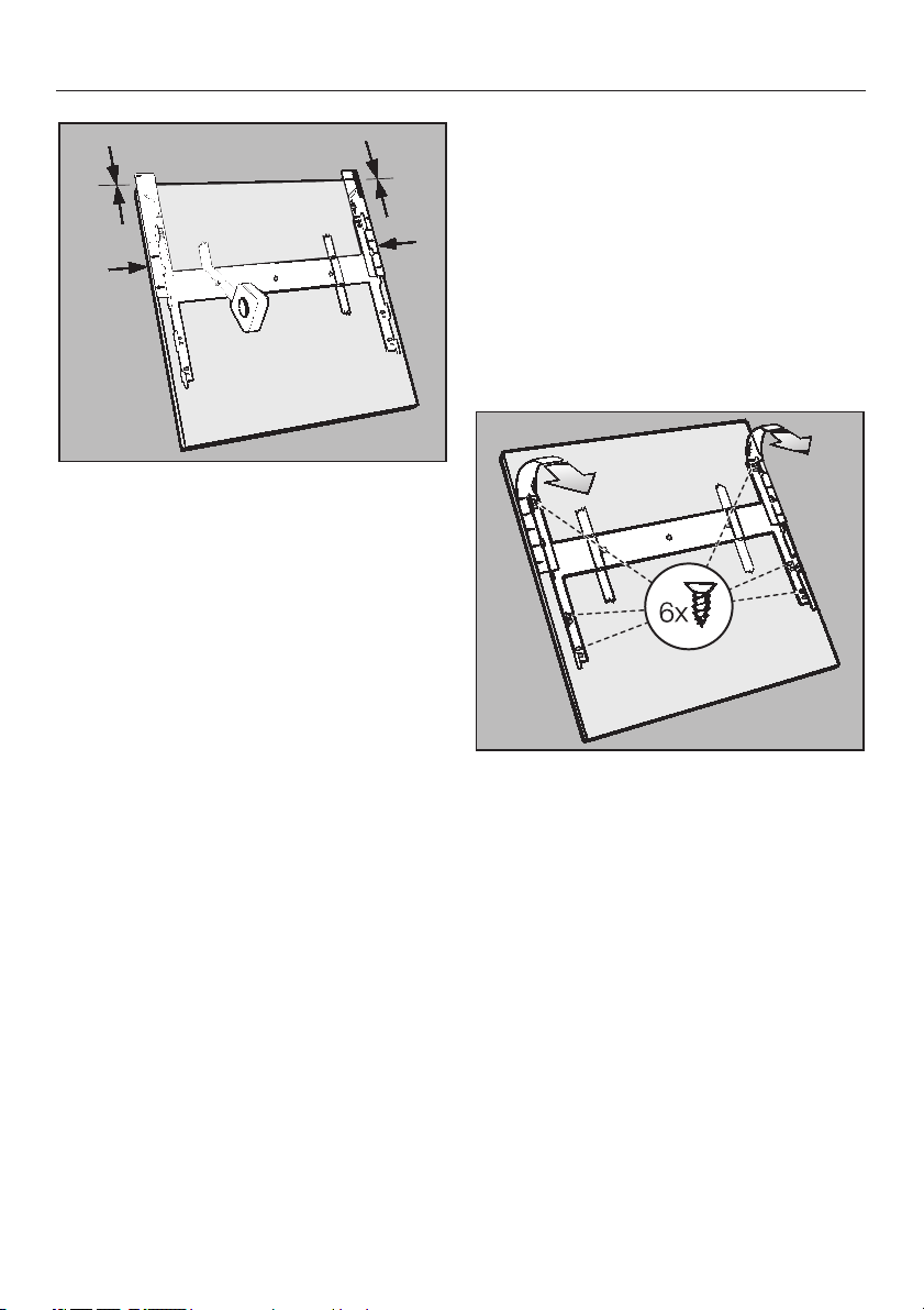
Tape the bracket to the door panel to
^
hold it in place while the mounting
holes are being drilled.
^ Proceed to step “Drill pilot holes ...”.
If the adjacent cabinetry (or appliance) does not have drawers and
alignment to a drawer line is impossible:
^ Hang the bracket on the machine
door, without the templates, and
tighten the four locking screws on the
edges of the door panel.
^
Close the door.
Installation
Remove the bracket from the ma
^
chine door and place it on the rear of
the door panel so that:
the bracket is centered left to right,
–
and
the bottom of the bracket is aligned
–
with the (X) line.
Tape the bracket to the door panel to
^
hold it in place while the mounting
holes are being drilled.
^ Drill pilot holes for the screws using a
3/32" (2.5 mm) bit.
^
Attach the bracket to the panel using
the 6 screws provided.
-
^
Measure the distance from the adja
cent cabinet (or appliance) door bot
tom to the bottom of the mounting
bracket (X).
^
Using measurement (X), draw a line
on the rear of the door panel (X)
inches up from the bottom.
^
-
Remove the templates (if used).
The templates should be kept in case
you want to install a different door
panel on the dishwasher at a later date.
15
Page 16
Installation
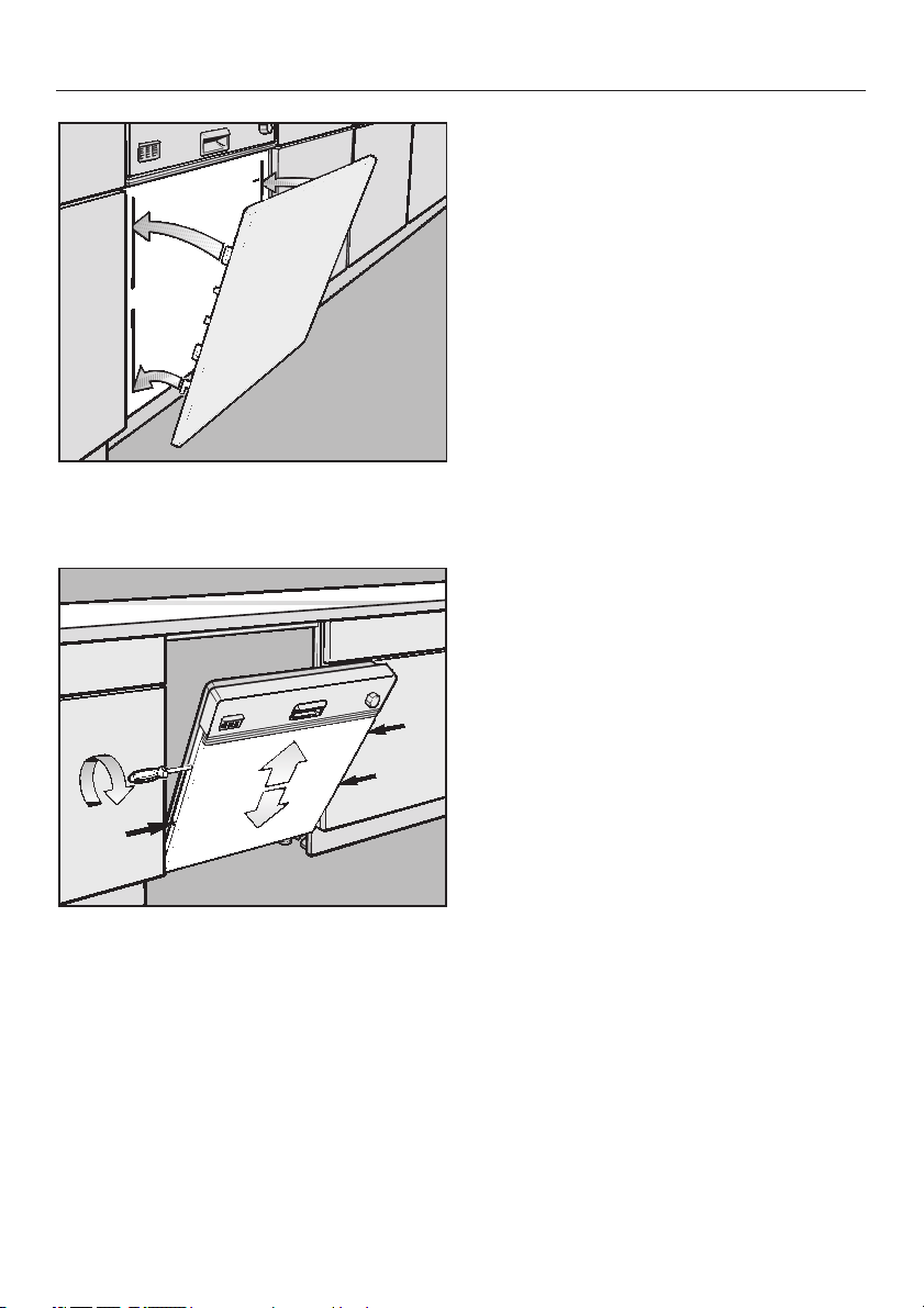
Attach the panel to the dishwasher
^
by aligning the bracket tabs with the
slots on the door.
Push up one side of the door panel
^
until it touches the spacer bars (or
control panel if spacer bars are not
being used) and lightly tighten the
T20 Torx screws on the correspond
ing edge of the machine door.
Repeat the process with the other
^
side of the door panel.
Shut the door.
^
Check that the door panel is ad
^
justed correctly. It should be snug at
the top and neatly aligned with the
cabinet drawer and door lines. If it is
not aligned properly, loosen the Torx
screws and readjust the panel
Once the door panel is positioned correctly:
^ Open the dishwasher door.
^ Tighten all the Torx screws on the
edges of the dishwasher door.
-
-
^
Open the dishwasher door slightly. If
the locking screws on the edge of
the dishwasher door can not be
reached, the dishwasher will have to
be pulled out of its opening a few
inches.
16
^ Use the provided caps to plug the
locking screw access holes.
Page 17
Installation
6.Securing the dishwasher
to the countertop
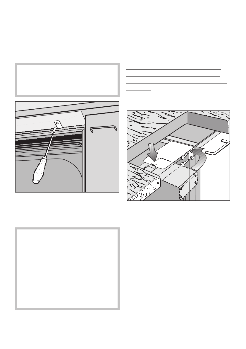
Open the dishwasher door.
^
If a steam deflector is installed un
der the countertop, the bracket
holes must align with the slots in the
deflector.
^ Using flat head screws, secure the
dishwasher to the countertop by
screwing through both the mounting
bracket and the steam deflector.
Make certain that the white rubber
seal located at the top, outer edge
of the dishwasher is tight against the
bottom of the countertop.
Do not drill any additional holes
through any portion of the wash
cabinet. If in doubt on how to secure
the dishwasher, please call the
Miele Technical Service Depart
ment.
-
For Corian® or granite countertops,
fasten the dishwasher to the adjoining
cabinets as follows:
-
For openings greater than 17 3/4"
(45 cm) wide (slimline models) or
23 5/8" (60 cm) wide (standard width
models):
Pull the dishwasher out from under
^
the countertop about 4" (10 cm).
^ Insert the tab (arrow) of each op-
tional side mounting bracket into the
guide hole on top of the dishwasher,
then swing it to the right or left as re
quired.
^
Push the dishwasher back into its
opening. Align and fasten it to the
adjacent cabinets using 2 screws for
each bracket.
-
17
Page 18
Installation
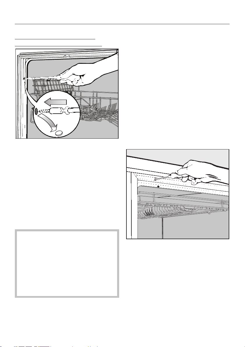
For openings exactly 17 3/4"
(45 cm) or 23 5/8" (60 cm) wide:
^ Open the dishwasher door and re-
move the caps covering the mounting holes on the outer edge of the
wash chamber.
^ Fasten the dishwasher to the adja-
cent cabinets using the supplied
screws and bushings. Make sure a
bushing is placed over the screw before inserting it into its mounting hole.
7.Adjusting the door springs
Open the dishwasher door halfway.
^
If the door remains in this position when
released, the springs are adjusted cor
rectly.
If the door drops, the tension on the
springs needs to be increased.
If it closes on its own, the tension on the
springs needs to be decreased.
The adjusting screw is located behind
the door in the upper front strip, on the
left hand side of the dishwasher.
The door springs are easier to adjust
when the door is only half open.
-
^
Tighten the screws and replace the
caps.
The side mounting holes should
only be used for securing the
dishwasher if the opening is ex
actly 17 3/4" (45 cm) wide (slim
line models) or 23 5/8" (60 cm)
wide (standard width models).
Use of this method on larger
openings will damage the ma
chine and cause leaks.
18
^
-
-
To adjust the door springs use a T20
Torx or a small slotted screwdriver
and turn the screw:
– clockwise to increase the
tension
– counterclockwise to decrease
the tension.
Page 19
Installation
8.Installing the toekick
For kitchens using one continuous
toekick or a cabinet matching toekick
To prevent damaging the front
panel, and before installing the
toekick, measurements must be
taken to ensure that the toekick will
not interfere with the complete
opening of the dishwasher door.
If the panel contacts the toekick
while the dishwasher door is being
opened, the dishwasher toekick must
be cut shorter or recessed deeper.
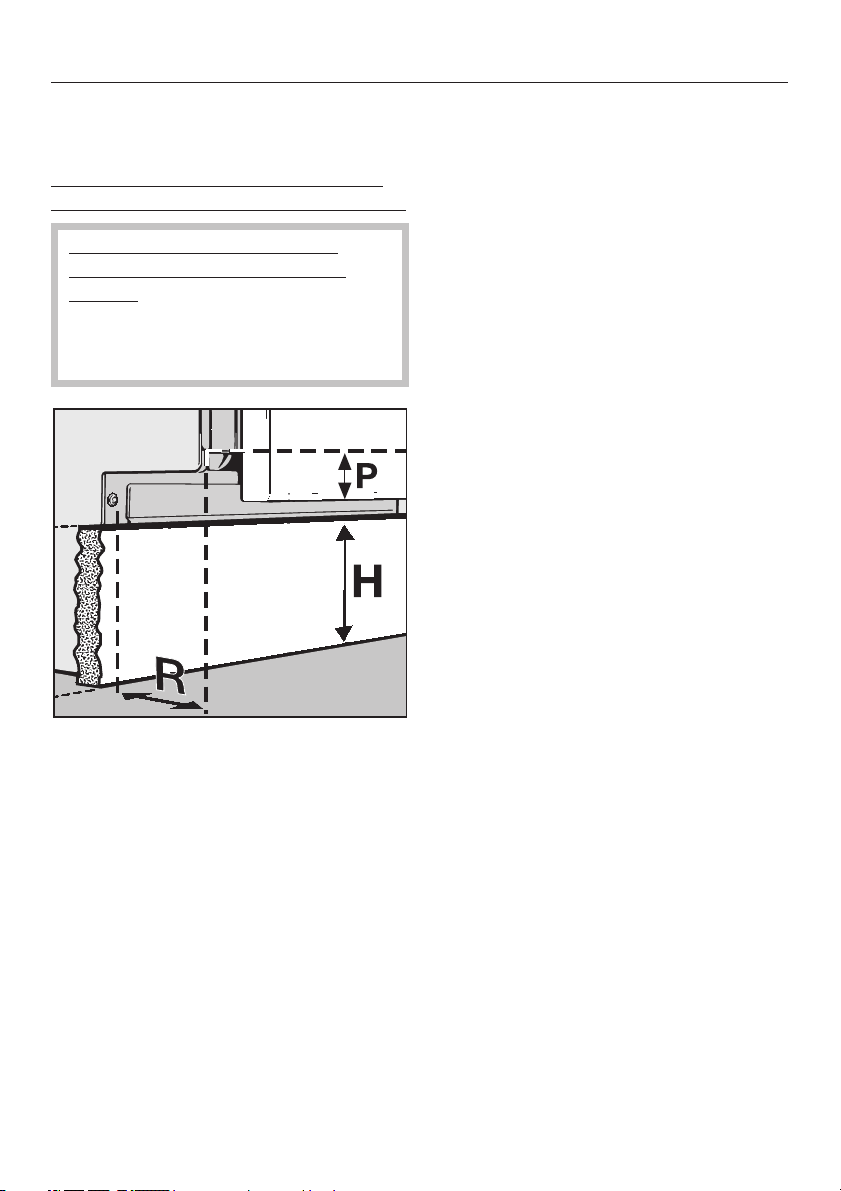
If (H) is equal to or less than the toekick
height of the adjoining cabinets, no in
terference will exist, provided that (R) is
at least 3/4".
Note: If a decorative or flush mount
toekick is desired, and (R) is less than
3/4", other modifications, such as bevel
ing the top rear edge of the toekick,
may be necessary. Install the toekick so
that it can be easily removed if service
is needed.
-
-
The panel overhang (P), and toekick
depth of recess (R), determine the
maximum dishwasher toekick height
(H).
19
Page 20
Installation
For kitchens using the included plastic
toekick
The included toekick will fit without
modification when:
The machine is set to its maximum
–
height (legs fully extended), and
the toekick is recessed as far as pos
–
sible (4" / 10 cm).
If the machine height is less than maxi
mum, or if the toekick is recessed less
than 4" (10 cm), the toekick must be
shortened (see following page).
After installation, carefully open the
dishwasher door to check that the
front panel does not hit the toekick.
If it does, remove the toekick and
trim it accordingly.
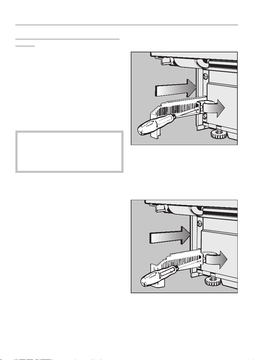
Adjusting the toekick recess
^ To adjust the depth (recess) of the
toekick, release the tension on the
spring clips (see illus) as shown, and
push the mounting brackets included
in the installation kit in as far as pos
sible.
Dishwasher model G 601 - G 691
(see data plate for model number)
-
-
The flange on the end of the mounting
brackets must point towards the center
of the machine.
Dishwasher model G 801 - G 891
(see data plate for model number)
-
20
^
The flange on the end of the mount
ing brackets must point towards the
outside of the machine.
-
Page 21
Installation
Trimming the toekick
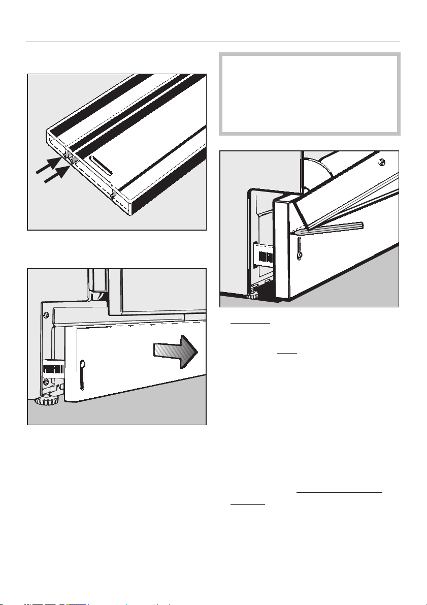
The rear of the toekick has two cutting
lines.
The toekick can not be pushed
back in. It must be unscrewed, so
that the tension on the spring
clips can be released. The brack
ets can then be pushed in, and
the toekick reattached.
^ Carefully
until it hits the toekick.
^ Using the front
door panel as a guide, draw a line
across the toekick.
open the dishwasher door
lower edge of the
-
^
Screw the toekick onto the installed
brackets, with the cutting lines to
wards the top, and pull out evenly
until it aligns with the toekick of the
adjoining cabinets.
^
Unscrew and remove the toekick.
^
If one of the cutting lines is close to
the line just drawn, score the front of
the toekick, and snap off the excess,
-
otherwise, trim the toekick along the
line using a saw.
^
Screw the toekick back onto the
brackets, with the cut edge at the
bottom.
If the dishwasher door does not open
completely, the toekick may need more
trimming.
21
Page 22

Electrical connection
Electrical connection
It is the responsibility of the con
sumer to ensure that the electrical
and plumbing installation is carried
out by a qualified installer in compli
ance with national and local codes
and ordinances.
Disconnect the appliance from the
power supply before servicing the ma
chine by pulling the plug or “tripping”
the circuit breaker.
Specifications
Power Supply: 120 VAC, 60 Hz
Rated Load: 12.5 A / 1500 W
Circuit breaker: 15 AMPS
The unit is equipped with a 4 ft (1.2 m)
power supply cord for connection to a
120 V, 15 AMP grounded receptacle.
Using an outlet:
^ It is recommended that the power
outlet for the appliance be installed
in a cabinet or on a wall adjacent
to the undercounter space in which
the appliance itself will be located.
An opening through the partition be
tween the compartments of 1 1/2"
(3 to 4 cm) can be made to allow
the plug to pass through.
-
Exercise care when sliding the dish
^
washer in or out, to prevent damag
ing the power cord or hoses.
-
GROUNDING INSTRUCTIONS
THIS APPLIANCE MUST BE
GROUNDED.
In the event of a malfunction or break
down, grounding will reduce the risk of
electric shock by providing a path of
least resistance for the electrical cur
rent. This appliance is equipped with a
cord having an equipment grounding
conductor and a grounding plug. The
plug must be plugged into an appropriate outlet that is installed and grounded
in accordance with all local codes and
ordinances.
WARNING - Improper connection
of the equipment grounding conductor can result in electric
shock. Check with a qualified
electrician or service representa
tive if there is a doubt that the ap
pliance is not properly grounded.
Do not modify the plug provided
-
with the appliance; if it will not fit
the outlet, have a proper outlet in
stalled by a qualified electrician.
-
-
-
-
-
-
-
^
Make certain that there are no rough
edges that could damage the power
cord. If metal cabinets are used,
place the supplied rubber grommet
around the edge of the opening be
fore passing the cable through.
22
-
Page 23
Permanent Connection (Hard Wiring)
For hard wiring, the power cord must
be disconnected from the terminal box
located at the lower left front of the
dishwasher, behind the toekick and ser
vice panel. Pass the permanent power
supply cable through the strain relief
and secure it to the terminal box.
Connect:
L1 (Black) to L on terminal block
N (White) to N on terminal block
GRND To ground connector
GROUNDING INSTRUCTIONS
This appliance must be connected
to a grounded metal, permanent wiring system, or an equipment
grounding conductor must be run
with the circuit conductors and connected to the equipment grounding
terminal or lead on the appliance.
Electrical connection
-
Use copper conductors only.
Warning
Hardwiring the dishwasher should
only be done if required by local
electrical codes, and then in ac
cordance with those codes. Do
not cut the plug off the power
supply cord and connect it di
rectly to the house wiring.
-
-
23
Page 24
Plumbing
Plumbing
It is the responsibility of the con
sumer to ensure that the electrical
and plumbing installation is carried
out by a qualified installer in compli
ance with national and local codes
and ordinances.
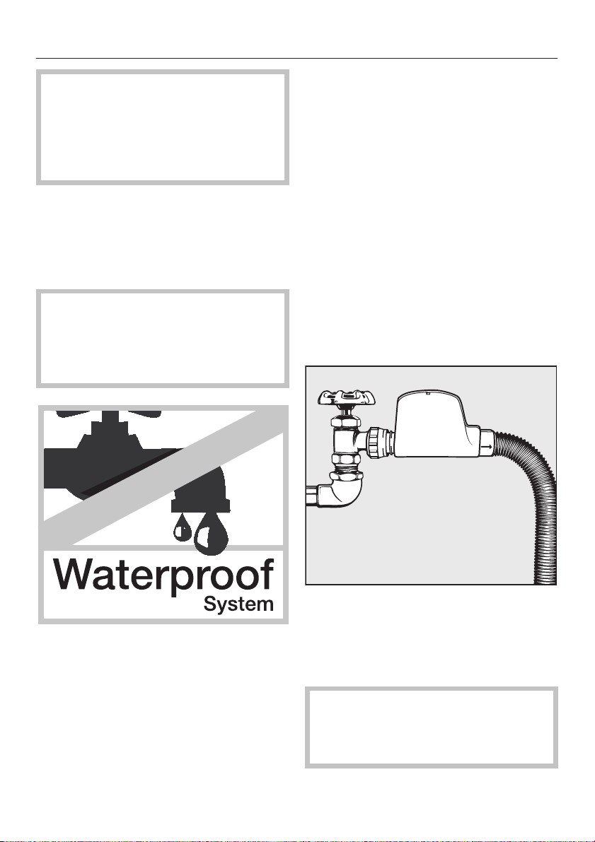
All dishwashers that carry the following
blue and white sticker are designed to
shut off the water and drain the wash
chamber in the rare event of an internal
water valve failure.
In order for this feature to be ac
tive, the machine must be “On”
(not necessarily running), and the
door must be closed when the
dishwasher is not being used.
-
-
-
The dishwasher can internally heat wa
ter to the temperatures required by the
wash program. This capability allows
the option of connecting the machine to
either a hot or cold water source.
For lowest energy consumption con
^
nect the dishwasher to a cold water
source.
For fastest possible wash times, with
^
slightly higher energy consumption,
connect the dishwasher to a hot wa
ter source.
Water connection
New plumbing:
-
-
-
Hot water supply specifications:
Recommended temperature:
120 °F (49 °C)
Maximum temperature: 140 °F (60 °C)
Water pressure:
14.5 - 145 psi (1.0 - 10 bar)
An air gap is built into the water inlet
system to prevent potable water from
mixing with waste water.
24
The water inlet hose comes equipped
with a 3/4" female hose thread connec
tor. This can be directly connected to a
shut off valve with 3/4" male hose
thread ends.
It is preferable that the hose as
sembly be installed vertically so
the hose exits from the bottom of
the valve box (not shown).
-
-
Page 25
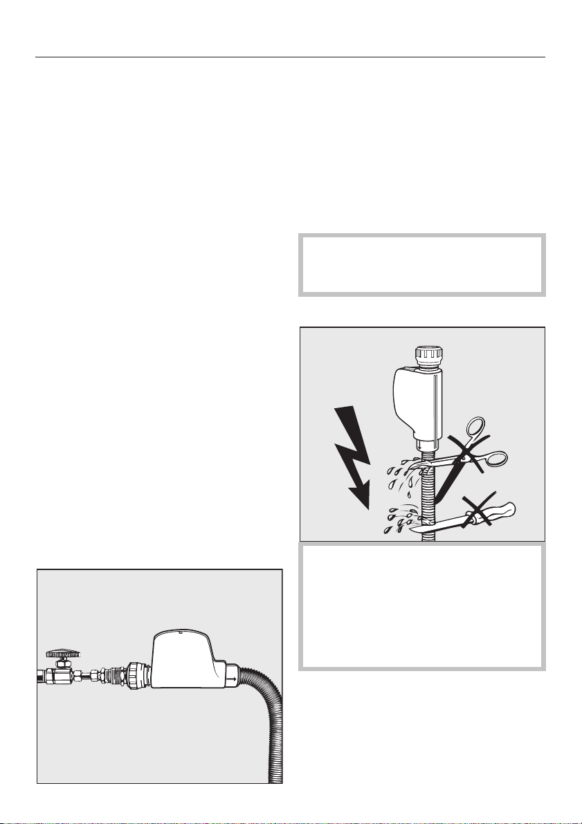
Plumbing
If this is not possible, it can be installed
horizontally, provided the hose exit re
mains beneath the main body of the
valve box (see illustration). The valve
box should also be installed so that it is
at least 10" (24 cm) above the floor (or
base of the cabinet), so that the excess
coiled hose will remain lower than the
valve box at all points.
A 2" x 4" (60 x 115 mm) cutout in either
the side or bottom of the cabinet adjoin
ing the dishwasher is necessary if the
valve box needs to be passed through.
The water pressure must be between
the pressure values as shown in the
Technical data section.
If the water pressure is too low, the “Intake/Drain” indicator may flash (see
“Solving problems” in the operating instructions).
If the water pressure is too high, a pressure reducer must be installed.
Existing plumbing:
If the standard 3/8" copper plumbing
for a dishwasher already exists with a
compression fitting and valve as pic
tured:
-
-
Cut the 3/8" copper tubing after the
^
valve.
Install the 3/8" compression to 3/4"
^
MHT (Male Hose Thread) adapter
(supplied with the machine), as illus
trated.
Connect the inlet hose to the existing
^
valve/adapter assembly.
Electrical wiring and components
should not come into contact with
any plumbing fixtures or hoses.
Do not, under any circumstances,
cut the intake hose. If the hose is
cut, the dishwasher will not work.
There will be a water leak and you
could be injured. If the hose is too
long, coil it neatly and place it be
hind the machine.
-
-
25
Page 26
Plumbing
Drainage system specifications:
The machine comes equipped with:
A 5 ft. long (1.5 m) flexible drain hose
–
with an internal diameter of 7/8"
(22 mm).
A built in swivel connector which al
–
lows the drain hose to be routed in
any direction.
A built in non-return valve on the dis
–
charge side to prevent waste water
from flowing back into the dish
washer.
– A built in odor trap on the discharge
side to prevent odors from entering
the kitchen.
Maximum drain height: 3 ft (1 m)
Maximum drain hose length: 12 ft
(3.5 m)
Do not shorten the drain hose.
Electrical wiring and components
should not come into contact with
any plumbing fixtures or hoses.
IMPORTANT:
The dishwasher should be con
nected directly to the drain line.
-
-
Drain connection:
-
-
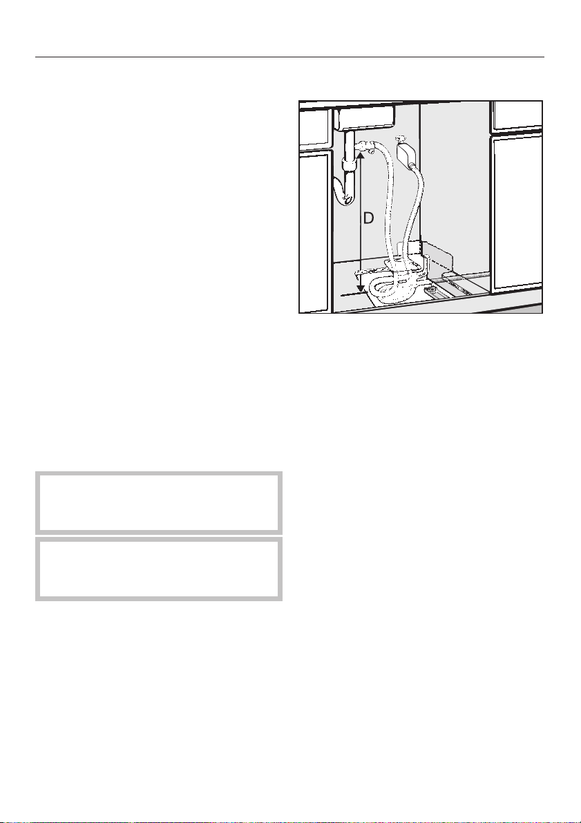
D = 24" (60 cm)
Connect the supplied drain hose to the
drain pipe of the kitchen sink either:
A - above the trap using the clamp pro-
vided, or
B - to the dishwasher connector of the
garbage disposal.
When connecting the drain hose to
the garbage disposal, make sure to
remove the knockout from the con
nection nipple. (See disposal manu
facturer’s instructions for this proce
dure.)
A sample of a correct water and drain
installation of a dishwasher is shown.
-
-
-
26
Page 27
Plumbing
Venting the drainage system
If the dishwasher drain hose is con
nected to a floor drain or to a drain
pipe that is below the level of the
lower baskets wheels, the drain must
be vented; otherwise the water inside
the dishwasher may siphon out during
the course of a wash program.
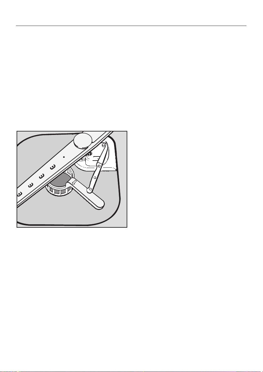
To vent the drain:
Open the dishwasher door.
^
-
Additional note
Since all Miele dishwashers are
equipped with an odor trap and non-re
turn valve, the drain hose can be con
nected directly to the drain pipe as il
lustrated.
If plumbing codes require an external
air gap on the discharge side of the
dishwasher, the following requirements
must be met:
No part of the drain hose should be
–
higher than 39" (1 m).
If installed horizontally, the drain
–
hose can be up to 12 ft. (3.5 m) long.
If the drain hose is angled upwards
in any way, it cannot be longer than
5 ft. (1.5 m).
– The drain connection should be
made as close as possible to the
dishwasher.
– The internal diameter (7/8" or 22 mm)
of the drain hose should not be reduced at any point.
-
-
-
^
Cut off the vent cap located at the
right rear of the dishwasher, behind
the filters, as illustrated
27
Page 28

Accessories
Accessories
If you would like... You will need...
...to secure the dishwasher to a
stone/marble countertop
...to convert the dishwasher to a
“U” model
...to adjust the dishwasher to a
height between 34 1/4" (870 mm) and
36 1/4" (920 mm) (G 6XX) or
between 35" (890 mm) and 37"
(940 mm) (G 8XX)
...to align the dishwasher control
panel with an adjacent drawer
front with a dimension of between
5 3/4" - 6" (145 mm - 154 mm)
...two fixing angles, part # 3341080
...a GDU kit (decor set)
available in: white
black
stainless steel
(depending on model)
...four extended machine feet,
part # 2702601
...an additional spacer bar
available in:
white, part # 4047341
black, part # 4047361
stainless steel, part # 3280742 and
3298210
These parts can be ordered from your Miele Dealer or from the Miele Technical
Service department.
28
Page 29

Technical Data
Technical Data
Series designation HG02
Dishwasher model * G 601 - G 624 G 801 - G 824
Height 32 1/4" (82 cm)
adjustable to
34 7/8" (88.6 cm)
Width of machine 17 1/2" (44.8 cm) 17 1/2" (44.8 cm)
Width of opening 17 3/4" (45 cm) 17 3/4" (45 cm)
Depth 22 1/2" (57 cm) 22 1/2" (57 cm)
Depth with door open 45 1/2" (116 cm) 47 1/2" (120,5 cm)
Weight 106 Ibs. (48 kg) 108 Ibs. (49 kg)
Voltage 110/120 V AC 110/120 V AC
Rated load 12.5 A / 1500 W 12.5 A / 1500 W
Fuse rating 15 A 15 A
Water pressure 14.5 - 145 psi
(1 - 10 bar)
Water connection Max 140 °F (60 °C) Max 140 °F (60 °C)
Drain height max. 3 ft (1 m) 3 ft (1 m)
Drain length max. 12 ft (3.5 m) 12 ft (3.5 m)
Power cord length approx. 4 ft (1.2 m) approx. 4 ft (1.2 m)
Capacity 8 place settings 9 place settings
33 1/8" (84 cm)
adjustable to
35" (89 cm)
14.5 - 145 psi
(1 - 10 bar)
* the dishwasher model can be found on the data plate
29
Page 30

Technical Data
Series designation HG01
Dishwasher model * G 640 - G 657 G 840 - G 857
Height 32 1/4" (82 cm)
adjustable to
34 7/8" (88.6 cm)
Width of machine 23 9/16" (59.8 cm) 23 9/16" (59.8 cm)
Width of opening 23 5/8" (60 cm) 23 5/8" (60 cm)
Depth 22 1/2" (57 cm) 22 1/2" (57 cm)
Depth with door open 45 1/2" (116 cm) 47 1/2" (120,5 cm)
Weight approx. 119 Ibs.
(54 kg)
Voltage 110/120 V AC 110/120 V AC
Rated load 12.5 A / 1500 W 12.5 A / 1500 W
Fuse rating 15 A 15 A
Water pressure 14.5 - 145 psi
(1 - 10 bar)
Water connection Max 140 °F (60 °C) Max 140 °F (60 °C)
Drain height max. 3 ft (1 m) 3 ft (1 m)
Drain length max. 12 ft (3.5 m) 12 ft (3.5 m)
Power cord length approx. 4 ft (1.2 m) approx. 4 ft (1.2 m)
Capacity 12 place settings 14 place settings
33 1/8" (84 cm)
adjustable to
35" (89 cm)
approx. 121 Ibs.
(55 kg)
14.5 - 145 psi
(1 - 10 bar)
* the dishwasher model can be found on the data plate
30
Page 31

Technical Data
Series designation HG01
Dishwasher model * G 674 - G 691 G 881 - G 891
Height 32 1/4" (82 cm)
adjustable to
34 7/8" (88.6 cm)
Width 23 9/16" (59.8 cm) 23 9/16" (59.8 cm)
Width of opening 23 5/8" (60 cm) 23 5/8" (60 cm)
Depth 22 1/2" (57 cm) 22 1/2" (57 cm)
Depth with door open 45 1/2" (116 cm) 47 1/2" (120,5 cm)
Weight approx. 123 Ibs.
(56 kg)
Voltage 110/120 V AC 110/120 V AC
Rated load 12.5 A / 1500 W 12.5 A / 1500 W
Fuse rating 15 A 15 A
Water pressure 4.5 - 145 psi
(0.3- 10 bar)
Water connection Max 140 °F (60 °C) Max 140 °F (60 °C)
Drain height max. 3 ft (1 m) 3 ft (1 m)
Drain length max. 12 ft (3.5 m) 12 ft (3.5 m)
Power cord length approx. 4 ft (1.2 m) approx. 4 ft (1.2 m)
Capacity 12 place settings 14 place settings
33 1/8" (84 cm)
adjustable to
35" (89cm)
approx. 123 Ibs.
(56 kg)
4.5 - 145 psi
(0.3 - 10 bar)
* the dishwasher model can be found on the data plate
31
Page 32

Alteration rights reserved (NovoB,P,S) / 004 3300
These instructions are printed on 100% recycled paper and are completely Biodegradable.
 Loading...