

Miele G 811, G 841, G 841 Plus, G 851, G 851 Plus Technical Information
...
TECHNICAL INFORMATION
G 600 and G 800 Dishwashers
(All US Models)
© 2011 Miele USA

Technical Information
G 600/G 800
Table of Contents
1.0 Construction and Design ....................................................................................... 12
1.1 Appliance Overview .................................................................................................. 12
1.1.1 Typical Integrated Model .............................................................................. 12
1.1.2 Typical Fully Integrated Model ...................................................................... 13
1.2 Control Panels .......................................................................................................... 13
1.2.1 Novotronic .................................................................................................... 13
1.2.2 Touchtronic ................................................................................................... 14
1.2.3 Incognito ....................................................................................................... 14
1.3 Types of Dishwashers ............................................................................................... 14
1.3.1 Pre-Finished ................................................................................................. 14
1.3.2 Integrated ..................................................................................................... 15
1.3.3 Fully Integrated ............................................................................................. 15
1.4 Technical Data .......................................................................................................... 16
1.4.1 Dishwasher Width – Full-Size/Slimline ......................................................... 16
1.4.2 Dishwasher Heights – 600/800 Series .......................................................... 16
1.4.3 Summary of Dimensions ............................................................................... 17
1.4.4 Electrical Information .................................................................................... 17
1.4.5 Hard-Wired Electrical Connection ................................................................. 17
1.4.6 Plumbing Connections .................................................................................. 18
1.4.6.1 Intake Connection ............................................................................. 18
1.4.6.2 Drain Connection .............................................................................. 18
1.5 Data Tag ................................................................................................................... 18
1.6 Layout of Components .............................................................................................. 19
1.6.1 Novotronic and Touchtronic Series ............................................................... 19
1.6.2 Incognito Series ............................................................................................ 20
2.0 Installation ............................................................................................................... 21
3.0 Commissioning and Operation .............................................................................. 22
3.1 Door Handle and Door Lock (Novotronic/Touchtronic Series) .................................. 22
3.2 Closing the Dishwasher Door .................................................................................... 22
3.3 Child Safety Lock ...................................................................................................... 22
3.4 Water Softener .......................................................................................................... 23
3.4.1 Water Softener Salt ...................................................................................... 23
3.5 General Operation .................................................................................................... 23
3.5.1 Novotronic Series ......................................................................................... 23
3.5.2 Touchtronic Series ........................................................................................ 24
3.5.3 Incognito Series ............................................................................................ 24
4.0 Description of Function .......................................................................................... 24
4.1 Cabinet Construction ................................................................................................ 24
4.2 Fan Assembly (Machines Equipped w/Turbothermic Fan) ........................................ 24
4.2.1 PTC Release Element (Machines Equipped w/Turbothermic Fan) ............... 25
4.3 Combination Dispenser ............................................................................................. 25
4.3.1 Construction ................................................................................................. 25
4.3.2 Dispensing .................................................................................................... 25
4.4 Heaters ..................................................................................................................... 26
4.4.1 Wash Cavity Heater Element ........................................................................ 26
4.4.2 Flow-Through Heater .................................................................................... 27
4.5 Heater Circuit Operation ........................................................................................... 28
4.6 Pulsed Heating – Operation ...................................................................................... 28
4.7 Temperature Protection ............................................................................................ 29
2

G 600/G 800
Technical Information
4.8 Static Drying .............................................................................................................. 29
4.9 Spray Arms ............................................................................................................... 29
4.10 Filter Assembly ......................................................................................................... 29
4.11 Water Intake – Technical Data .................................................................................. 30
4.12 WaterProof System (WPS) ....................................................................................... 30
4.13 Flow Meter – Operation ............................................................................................ 33
4.14 Water Intake .............................................................................................................. 33
4.15 Water Mixing ............................................................................................................. 33
4.15.1 External Flow Meter ...................................................................................... 33
4.15.2 Integrated Flow Meter ................................................................................... 35
4.15.3 Operating Solenoid Valve (Y5) (Plus Models Only) ...................................... 36
4.16 Electronically Controlled Water Hardness (EGS) ...................................................... 37
4.17 Water Softener .......................................................................................................... 37
4.17.1 Reactivation .................................................................................................. 38
4.17.2 Reactivation Cycles ...................................................................................... 38
4.18 Condenser Drying (UKT) .......................................................................................... 39
4.18.1 Operation ...................................................................................................... 39
4.18.2 Technical Data .............................................................................................. 39
4.18.3 Control Valve ................................................................................................ 39
4.19 Drain Pump, Circulation Pump .................................................................................. 40
4.20 Heater Level Switch (Heater Pressure Switch) ......................................................... 41
4.21 Level Switch (Intake Overflow) .................................................................................. 42
4.22 Temperature Sensor ................................................................................................. 43
4.23 Top Solo Valve .......................................................................................................... 44
4.24 Turbidity Sensor (ECO Sensor) ................................................................................ 45
4.25 Electronic – Power Outputs....................................................................................... 45
4.25.1 Programming after Replacing the Electronic ................................................ 46
4.25.2 Electronic Modes .......................................................................................... 46
5.0 Service and Maintenance ....................................................................................... 47
5.1 Locking Plate Adjustment ......................................................................................... 47
5.2 Door Seal Replacement ............................................................................................ 47
5.3 Side Panel Removal ................................................................................................. 48
5.4 Spring Bracket Replacement .................................................................................... 49
5.5 Cover Plate Removal ................................................................................................ 49
5.6 Connecting Strip Removal ........................................................................................ 50
5.7 Basket Support Roller Replacement ......................................................................... 50
5.8 Removing the Combination Dispenser ...................................................................... 52
5.9 Turbothermic Fan Removal....................................................................................... 53
5.10 Door Panel (Outer and Inner) Removal .................................................................... 53
5.11 Cable Holder Removal .............................................................................................. 54
5.12 Lock/Handle Assembly Removal .............................................................................. 55
5.13 Door Hinge Removal ................................................................................................. 55
5.14 Door Tension Adjustment ......................................................................................... 56
5.15 Top Spray Arm Removal ........................................................................................... 56
5.16 Middle Spray Arm Removal ...................................................................................... 57
5.17 Bottom Spray Arm Removal...................................................................................... 57
5.18 Top Spray Arm Feed Pipe Removal ......................................................................... 57
5.19 Middle Spray Arm Cover Removal ............................................................................ 57
5.20 Middle Spray Arm Feed Pipe Removal ..................................................................... 58
5.21 Flow-Through Heater Removal ................................................................................. 58
5.22 Temperature Limiter Replacement ............................................................................ 59
5.23 Microfine Filter Replacement .................................................................................... 59
5.24 WaterProof System (WPS) Removal ........................................................................ 60
3

Technical Information
G 600/G 800
5.25 WaterProof System (WPS) Restrictor Replacement ................................................. 60
5.26 Water Inlet (Diverter) Removal .................................................................................. 61
5.27 Water Softener Operational Check ........................................................................... 62
5.28 Water Softener Assembly Removal .......................................................................... 62
5.29 Drip Pan Removal ..................................................................................................... 63
5.30 Float Switch Housing Removal ................................................................................. 63
5.31 Float Switch (B8/3) Removal..................................................................................... 63
5.32 Steam Condenser Removal ...................................................................................... 63
5.33 Control Valve (Y6) Removal...................................................................................... 64
5.34 Temperature Sensor (NTC) Removal ....................................................................... 64
5.35 Circulation Pump (M6) Removal ............................................................................... 64
5.36 Circulation Pump Partition and Impeller Replacement .............................................. 65
5.37 Circulation Pump Housing Replacement .................................................................. 66
5.38 Circulation Pump Release with Tool ......................................................................... 66
5.39 Heater Pressure Switch (B1/10) Removal ................................................................ 67
5.40 Drain Pump (M8) Removal ....................................................................................... 68
5.41 Top Solo Valve Removal .......................................................................................... 68
5.42 Overflow Level Switch Removal ................................................................................ 69
5.43 Sump Removal ......................................................................................................... 69
5.44 Turbidity Sensor Calibration ...................................................................................... 70
5.45 Turbidity Sensor Removal ......................................................................................... 71
5.46 Fully Integrated (Vi) Control Panel Removal ............................................................. 71
5.47 Novotronic and Touchtronic Control Panel Removal ................................................ 71
5.48 Mounting Bracket Removal ....................................................................................... 72
5.49 Heater Relay and Power Relay Removal .................................................................. 73
6.0 Fault Diagnosis ....................................................................................................... 74
6.1 General Information .................................................................................................. 74
6.2 Programming and Service Mode Features ............................................................... 74
6.2.1 Water Hardness Programming ..................................................................... 74
6.2.2 Drying Options (As Applicable) ..................................................................... 74
6.2.3 Water Intake Duration ................................................................................... 74
6.2.4 Buzzer (As Applicable) ................................................................................. 74
6.2.5 Fault Code Retrieval ..................................................................................... 74
6.2.6 Increase Temperature .................................................................................. 74
6.2.7 With or Without Water Softener .................................................................... 75
6.2.8 2nd Interim Rinse .......................................................................................... 75
6.2.9 Width of Machine (As Applicable) ................................................................. 75
6.2.10 Flow Meter Count ......................................................................................... 75
6.2.11 Operating Hours ........................................................................................... 75
6.3 Programming/Service Mode Access Procedures (Model-Specific) ........................... 75
6.4 Timing Charts – General Information ........................................................................ 76
6.5 Wiring Diagrams – General Information .................................................................... 79
6.6 Timing Charts and Wiring Diagrams (Model-Specific) .............................................. 80
6.7 Fault Repair .............................................................................................................. 80
6.7.1 Door Does Not Close Correctly..................................................................... 80
6.7.2 Excess Foaming ........................................................................................... 80
6.7.3 Detergent Not Released ............................................................................... 80
6.7.4 Water Leaks from the Turbothermic Fan Grille ............................................. 80
6.7.5 Poor Drying Results ...................................................................................... 80
6.7.6 No Drying, or Drying Too Slow ..................................................................... 81
6.7.7 Water Not Heating ........................................................................................ 81
6.7.8 Circulation Pump Does Not Start .................................................................. 81
4

G 600/G 800
Technical Information
6.8 Programming and Service Modes ............................................................................. 82
Novotronic Models .................................................................................................... 82
6.8.1 G 841, G 841 Plus, G 842 ............................................................................ 82
6.8.1.1 Programming Mode .......................................................................... 82
6.8.1.1.1 Setting the Water Hardness .................................................... 83
6.8.1.1.2 Checking the Water Hardness Level ...................................... 83
6.8.1.2 Service Mode 1 ................................................................................. 83
6.8.1.2.1 Test Program .......................................................................... 84
6.8.1.3 Service Mode 2 ................................................................................. 84
6.8.1.3.1 Accessing Fault Codes ........................................................... 85
6.8.1.3.2 Deleting Stored Fault Codes ................................................... 85
6.8.1.3.3 Program Index ........................................................................ 85
6.8.2 G 848 ......................................................................................................... 86
6.8.2.1 Programming Mode .......................................................................... 86
6.8.2.1.1 Setting the Water Hardness .................................................... 87
6.8.2.1.2 Checking the Water Hardness Level ...................................... 87
6.8.2.2 Service Mode 1 ................................................................................. 87
6.8.2.2.1 Test Program .......................................................................... 87
6.8.2.3 Service Mode 2 ................................................................................. 88
6.8.2.3.1 Accessing Fault Codes ........................................................... 88
6.8.2.3.2 Deleting Stored Fault Codes ................................................... 89
6.8.2.3.3 Program Index ........................................................................ 89
6.8.3 G 811, G 851, G 851 Plus, G 856, G 856 Plus ............................................. 89
6.8.3.1 Programming Mode .......................................................................... 90
6.8.3.1.1 Setting the Water Hardness .................................................... 90
6.8.3.1.2 Checking the Water Hardness Level ...................................... 91
6.8.3.2 Service Mode 1 ................................................................................. 91
6.8.3.2.1 Test Program .......................................................................... 91
6.8.3.3 Service Mode 2 ................................................................................. 91
6.8.3.3.1 Accessing Fault Codes ........................................................... 92
6.8.3.3.2 Deleting Stored Fault Codes ................................................... 93
6.8.3.3.3 Program Index ........................................................................ 93
6.8.4 G 680, G 880 ................................................................................................ 93
6.8.4.1 Programming Mode .......................................................................... 93
6.8.4.1.1 Setting the Water Hardness .................................................... 94
6.8.4.1.2 Checking the Water Hardness Setting .................................... 95
6.8.4.2 Service Mode 1 ................................................................................. 95
6.8.4.2.1 Starting the Test Program, Program Start with Reactivation .. 96
6.8.4.3 Service Mode 2 ................................................................................. 96
6.8.4.3.1 Fault Code Display and Deletion ............................................ 96
6.8.4.3.2 Program Index ........................................................................ 97
6.8.4.3.3 Setting the Flow Meter ............................................................ 97
6.8.4.4 Other Fault Indications ..................................................................... 97
6.8.4.4.1 Program Interruption and All Program Sequence LEDs Flash 97
6.8.4.4.2 Program Interruption and Intake/Drain LED Flashes .............. 98
6.8.5 G 681, G 881 Novo Stella, G 886 Novo Stella Plus ...................................... 98
6.8.5.1 Programming Mode .......................................................................... 98
6.8.5.1.1 Setting the Water Hardness .................................................... 99
6.8.5.1.2 Checking the Water Hardness Level ...................................... 99
6.8.5.2 Service Mode 1 ................................................................................. 99
6.8.5.2.1 Test Program ........................................................................ 100
6.8.5.3 Service Mode 2 ............................................................................... 100
6.8.5.3.1 Accessing Fault Codes ......................................................... 101
6.8.5.3.2 Deleting Stored Fault Codes ................................................. 101
6.8.5.3.3 Operating Hours ................................................................... 101
6.8.6 G 885 ....................................................................................................... 101
6.8.6.1 Programming Mode ........................................................................ 102
6.8.6.2 Service Mode 1 (Switching Step Check) ........................................ 102
6.8.6.2.1 Starting the Test Program; Program Start with Reactivation 103
5

G 600/G 800
Technical Information
6.8.6.3
Service Mode 2 ............................................................................... 103
6.8.6.3.1 Fault Codes - Display and Deletion ...................................... 103
Touchtronic Models ................................................................................................. 104
6.8.7 G 890 ....................................................................................................... 104
6.8.7.1 Programming Mode ........................................................................ 104
6.8.7.1.1 Setting the Water Hardness .................................................. 105
6.8.7.1.2 Checking the Water Hardness Level .................................... 105
6.8.7.2 Service Mode 1 ............................................................................... 105
6.8.7.2.1 Test Program ........................................................................ 106
6.8.7.3 Service Mode 2 ............................................................................... 106
6.8.7.3.1 Accessing Fault Codes ......................................................... 106
6.8.7.3.2 Deleting Stored Fault Codes ................................................. 107
6.8.7.3.3 Operating Hours ................................................................... 107
6.8.8 G 891 ....................................................................................................... 107
6.8.8.1 Programming Mode ........................................................................ 108
6.8.8.1.1 Setting the Water Hardness .................................................. 108
6.8.8.1.2 Checking the Water Hardness Level .................................... 108
6.8.8.2 Service Mode 1 ............................................................................... 109
6.8.8.2.1 Test Program ........................................................................ 109
6.8.8.3 Service Mode 2 ............................................................................... 109
6.8.8.3.1 Accessing Fault Codes ......................................................... 110
6.8.8.3.2 Deleting Stored Fault Codes ................................................. 110
6.8.8.3.3 Operating Hours ................................................................... 110
6.8.9 G 892, G 832 .............................................................................................. 111
6.8.9.1 Programming Mode ........................................................................ 111
6.8.9.1.1 Setting the Water Hardness .................................................. 111
6.8.9.1.2 Extended Drying Fan Time ................................................... 112
6.8.9.2 Service Mode 1 ............................................................................... 112
6.8.9.2.1 Test Program ........................................................................ 113
6.8.9.3 Service Mode 2 ............................................................................... 113
6.8.9.3.1 Stage 1 ................................................................................. 113
6.8.9.3.2 Stage 2 ................................................................................. 114
6.8.9.3.3 Stage 3 ................................................................................. 114
6.8.10 G 694, G 894 .............................................................................................. 115
6.8.10.1 Programming Mode ........................................................................ 115
6.8.10.1.1 Setting the Water Hardness .................................................. 116
6.8.10.1.2 Extended Drying Fan Time ................................................... 116
6.8.10.2 Service Mode 1 ............................................................................... 116
6.8.10.2.1 Test Program ........................................................................ 116
6.8.10.3 Service Mode 2 ............................................................................... 116
6.8.10.3.1 Stage 1 ................................................................................. 117
6.8.10.3.2 Stage 2 ................................................................................. 117
6.8.10.3.3 Stage 3 ................................................................................. 117
6.8.11 G 896 ....................................................................................................... 118
6.8.11.1 Programming Mode ........................................................................ 119
6.8.11.1.1 Setting the Water Hardness .................................................. 119
6.8.11.1.2 Extended Drying Fan Time ................................................... 119
6.8.11.2 Service Mode 1 ............................................................................... 119
6.8.11.2.1 Test Program ........................................................................ 120
6.8.11.3 Service Mode 2 ............................................................................... 120
6.8.11.3.1 Stage 1 ................................................................................. 120
6.8.11.3.2 Stage 2 ................................................................................. 121
6.8.11.3.3 Stage 3 ................................................................................. 121
6.8.11.3.4 Stage 4 ................................................................................. 121
6.8.12 G 898 ....................................................................................................... 122
6.8.12.1 Programming Mode ........................................................................ 122
6.8.12.1.1 Setting the Water Hardness .................................................. 123
6.8.12.1.2 Checking the Water Hardness Level .................................... 123
6

G 600/G 800
Technical Information
6.8.12.2 Service Mode 1 ............................................................................... 123
6.8.12.2.1 Test Program ........................................................................ 123
6.8.12.3 Service Mode 2 ............................................................................... 123
6.8.12.3.1 Accessing Fault Codes ......................................................... 124
6.8.12.3.2 Deleting Stored Fault Codes ................................................. 125
6.8.12.3.3 Operating Hours ................................................................... 125
Incognito Models ..................................................................................................... 125
6.8.13 G 803, G 643, G 843, G 663, G 863 ........................................................... 125
6.8.13.1 Programming Mode ........................................................................ 125
6.8.13.1.1 Setting the Water Hardness Level ........................................ 126
6.8.13.1.2 Checking the Water Hardness Level .................................... 126
6.8.13.2 Service Mode 1 ............................................................................... 127
6.8.13.2.1 Test Program ........................................................................ 127
6.8.13.3 Service Mode 2 ............................................................................... 128
6.8.13.3.1 Accessing Fault Codes ......................................................... 128
6.8.13.3.2 Deleting Stored Fault Codes ................................................. 129
6.8.13.3.3 Program Index ...................................................................... 129
6.8.14 G 818, G 658, G 858 .................................................................................. 129
6.8.14.1 Programming Mode ........................................................................ 130
6.8.14.1.1 Setting the Water Hardness Level ........................................ 130
6.8.14.1.2 Checking the Water Hardness Level .................................... 130
6.8.14.2 Service Mode 1 ............................................................................... 131
6.8.14.2.1 Test Program ........................................................................ 131
6.8.14.3 Service Mode 2 ............................................................................... 132
6.8.14.3.1 Accessing Fault Codes ......................................................... 132
6.8.14.3.2 Deleting Stored Fault Codes ................................................. 133
6.8.14.3.3 Program Index ...................................................................... 133
6.8.15 G 879 ....................................................................................................... 133
6.8.15.1 Programming Mode ........................................................................ 134
6.8.15.1.1 EPLG 501A (Program Index P1)........................................... 134
6.8.15.1.2 EPLZ 530 (Program Index P2 or Higher) .............................. 134
6.8.15.1.3 Setting the Water Hardness .................................................. 135
6.8.15.1.4 Checking the Water Hardness Level .................................... 135
6.8.15.2 Service Mode 1 ............................................................................... 135
6.8.15.2.1 Test Program ........................................................................ 136
6.8.15.3 Service Mode 2 ............................................................................... 136
6.8.15.3.1 Fault Code Access ................................................................ 137
6.8.15.3.2 Deleting Stored Fault Codes ................................................. 137
6.8.15.3.3 Program Index ...................................................................... 137
List of Figures
Figure 1-1: Overview of Typical Integrated Model ................................................................. 12
Figure 1-2: Overview of Typical Fully Integrated Model ........................................................ 13
Figure 1-3: Novotronic Control Panel (G 841 Shown) ........................................................... 14
Figure 1-4: Touchtronic Control Panels (G 832 Shown) ........................................................ 14
Figure 1-5: Incognito Control Panels (G 818 Shown) ............................................................ 14
Figure 1-6: Pre-Finished Dishwasher .................................................................................... 15
Figure 1-7: Integrated Dishwasher ........................................................................................ 15
Figure 1-8: Fully Integrated Dishwasher ............................................................................... 16
Figure 1-9: Dishwasher Widths ............................................................................................. 16
Figure 1-10: Dishwasher Heights .......................................................................................... 16
Figure 1-11: Data Tag Location ............................................................................................. 18
Figure 1-12: Data Tag Information ........................................................................................ 18
Figure 1-13: Component Overview – Novotronic & Touchtronic Series ................................ 19
Figure 1-14: Component Overview – Incognito (Vi) Series ................................................... 20
7

Technical Information
G 600/G 800
Figure 3-1: Door Handle and Door Lock (Novotronic/Touchtronic) ....................................... 22
Figure 3-2: Child Safety Lock ................................................................................................ 22
Figure 3-3: Filling the Salt Container ..................................................................................... 23
Figure 4-1: Dispenser Assembly ........................................................................................... 25
Figure 4-2: Cavity-Style Heater Element ............................................................................... 26
Figure 4-3: Flow-Through Heater Element ............................................................................ 27
Figure 4-4: Heater Circuit ...................................................................................................... 28
Figure 4-5: Filter Assembly ................................................................................................... 30
Figure 4-6: WaterProof System Connection .......................................................................... 31
Figure 4-7: WaterProof System Circuit - Normal Operating Position ..................................... 32
Figure 4-8: WPS Circuit - Water in Drip Pan Activates Float Switch B8/3 ............................. 32
Figure 4-9: Flow Meter Assembly Components (External Flow Meter Shown) ..................... 33
Figure 4-10: Water Intake System with Integrated Flow Meter .............................................. 34
Figure 4-11: Water Hardness Selector .................................................................................. 34
Figure 4-12: Water Path with Integrated Flow Meter ............................................................. 35
Figure 4-13: Water Inlet Mixer ............................................................................................... 36
Figure 4-14: Water Hardness Mixer Solenoid ....................................................................... 37
Figure 4-15: Water Softener .................................................................................................. 38
Figure 4-16: Condenser Drying System Components ........................................................... 40
Figure 4-17: Control Valve Y6 ............................................................................................... 40
Figure 4-18: Heater Pressure Switch – Contact Positions and Current Paths....................... 42
Figure 4-19: Water Intake/Level Switch Circuit ..................................................................... 43
Figure 4-20: Circulation Pump, Highlighting Components for the Top Solo Feature ............. 44
Figure 4-21: Turbidity Sensor (ECO Sensor) ........................................................................ 45
Figure 5-1: Locking Plate ...................................................................................................... 47
Figure 5-2: Seal Install Guide ................................................................................................ 48
Figure 5-3: Side Panel Removal ........................................................................................... 48
Figure 5-4: Side View, Door with Basket ............................................................................... 49
Figure 5-5: Cover Plate ......................................................................................................... 50
Figure 5-6: Toekick Area with Connecting Strip .................................................................... 50
Figure 5-7: Basket Guide ...................................................................................................... 51
Figure 5-8: Clip with Bolt ....................................................................................................... 51
Figure 5-9: Basket Guide Stopper ......................................................................................... 52
Figure 5-10: Stopper Removal .............................................................................................. 52
Figure 5-11: Combination Dispenser Removal ...................................................................... 53
Figure 5-12: Turbothermic Fan Removal............................................................................... 53
Figure 5-13: Inner Door Panel Removal ................................................................................ 54
Figure 5-14: Cable Holder Removal ...................................................................................... 54
Figure 5-15: Lock Removal ................................................................................................... 55
Figure 5-16: Hinge Removal ................................................................................................. 56
Figure 5-17: Door Tension Adjustment Screw ....................................................................... 56
Figure 5-18: Middle Spray Arm Cover Removal .................................................................... 57
Figure 5-19: Flow-Through Heater Assembly ........................................................................ 58
Figure 5-20: Microfine Filter Replacement ............................................................................ 59
Figure 5-21: Pressing and Locking the Filter Assembly ........................................................ 60
Figure 5-22: Tilting the Flow Restrictor ................................................................................. 60
Figure 5-23: Removing the Flow Restrictor ........................................................................... 61
Figure 5-24: Water Inlet Removal ......................................................................................... 61
Figure 5-25: Float Switch Housing ........................................................................................ 63
Figure 5-26: Steam Condenser Components ........................................................................ 64
Figure 5-27: Circulation Pump Removal................................................................................ 65
Figure 5-28: Circulation Pump Components ......................................................................... 66
8

G 600/G 800
Technical Information
Figure 5-29: Sliding the Circulation Pump Tool into the Circulation Pump Intake Opening ... 66
Figure 5-30: Engaging the Prongs in the Circulation Pump Impeller ..................................... 67
Figure 5-31: Turning the Circulation Pump Tool .................................................................... 67
Figure 5-32: Heater Pressure Switch and Circulation Pump ................................................. 68
Figure 5-33: Drain Pump Removal ........................................................................................ 68
Figure 5-34: Top Solo Valve on Circulation Pump ................................................................ 69
Figure 5-35: Releasing the Overflow Level Switch from the Connecting Strip ...................... 69
Figure 5-36: Self-Tensioning Sump Clamp ........................................................................... 70
Figure 5-37: Non-Self-Tensioning Sump Clamp; Tighten to a Gap of 22mm ........................ 70
Figure 5-38: Fully Integrated (Vi) Control Panel .................................................................... 71
Figure 5-39: Control Panel (Novotronic and Touchtronic) ..................................................... 72
Figure 5-40: Removing the Mounting Bracket ....................................................................... 73
List of Tables
Table 1-1: Summary of Dimensions ...................................................................................... 17
Table 4-1: Detergent Quantity in Combination Dispensers C2.06 and C2.09 ....................... 25
Table 4-2: Rinse Aid Dispensing (Combination Dispensers C2.06 and C2.09) ..................... 26
Table 4-3: Flow-Through Heater Electrical Data ................................................................... 28
Table 4-4: Spray Arm Rotation Speeds ................................................................................. 29
Table 4-5: WaterProof System Data ..................................................................................... 30
Table 4-6: Flow Restrictor Data ............................................................................................. 30
Table 4-7: Water Inlet Mixer Data ......................................................................................... 30
Table 4-8: Reactivation Cycle Timing .................................................................................... 39
Table 4-9: Circulation and Drain Pump Data ......................................................................... 41
Table 4-10: Temperature Sensor R30 Resistance Values .................................................... 44
Table 4-11: Activation of Components .................................................................................. 46
Table 6-1: G 841, G 841 Plus, G 842 Programming Flow Chart ........................................... 82
Table 6-2: G 841, G 841 Plus, G 842 Programming Functions ............................................. 83
Table 6-3: G 841, G 841 Plus, G 842 Water Hardness Chart ............................................... 83
Table 6-4: G 841, G 841 Plus, G 842 Service Mode 2 Functions .......................................... 84
Table 6-5: G 841, G 841 Plus, G 842 Fault Code Chart ........................................................ 85
Table 6-6: G 841, G 841 Plus, G 842 Program Indices ......................................................... 85
Table 6-7: G 848 Programming Flow Chart ........................................................................... 86
Table 6-8: G 848 Programming Functions ............................................................................ 86
Table 6-9: G 848 Water Hardness Chart ............................................................................... 87
Table 6-10: G 848 Service Mode 2 Functions ....................................................................... 88
Table 6-11: G 848 Fault Code Chart ..................................................................................... 89
Table 6-12: G 848 Program Indices ...................................................................................... 89
Table 6-13: G 811, G 851, G 851 Plus, G 856, G 856 Plus Programming Flow Chart .......... 90
Table 6-14: G 811, G 851, G 851 Plus, G 856, G 856 Plus Programming Functions ............ 90
Table 6-15: G 811, G 851, G 851 Plus, G 856, G 856 Plus Water Hardness Chart .............. 91
Table 6-16: G 811, G 851, G 851 Plus, G 856, G 856 Plus Service Mode 2 Functions ........ 92
Table 6-17: G 811, G 851, G 851 Plus, G 856, G 856 Plus Fault Code Chart ...................... 92
Table 6-18: G 811, G 851, G 851 Plus, G 856, G 856 Plus Program Indices........................ 93
Table 6-19: G 680, G 880 Programming Flow Chart ............................................................. 93
Table 6-20: G 680, G 880 Programming Functions ............................................................... 94
Table 6-21: G 680, G 880 Water Hardness Settings ............................................................. 95
Table 6-22: G 680, G 880 Program Sequence LEDs ............................................................ 95
Table 6-23: G 680, G 880 Service Mode 2 Functions ........................................................... 96
Table 6-24: G 680, G 880 Fault Codes ................................................................................. 97
Table 6-25: G 680, G 880 Program Indices........................................................................... 97
Table 6-26: G 681, G 881 Novo Stella, G 886 Novo Stella Plus Programming Flow Chart ... 98
9

Technical Information
G 600/G 800
Table 6-27: G 681, G 881 Novo Stella, G 886 Novo Stella Plus Programming Functions .... 99
Table 6-28: G 681, G 881 Novo Stella, G 886 Novo Stella Plus Service Mode 2 Functions 100
Table 6-29: G 681, G 881 Novo Stella, G 886 Novo Stella Plus Fault Code Chart ............. 101
Table 6-30: G 681, G 881 Novo Stella, G 886 Novo Stella Plus Operating Hours .............. 101
Table 6-31: G 885 Programming Flow Chart ....................................................................... 102
Table 6-32: G 885 Programming Functions ........................................................................ 102
Table 6-33: G 885 Service Mode 2 Functions ..................................................................... 103
Table 6-34: G 885 Fault Codes ........................................................................................... 104
Table 6-35: G 890 Programming Flow Chart ....................................................................... 104
Table 6-36: G 890 Programming Functions ........................................................................ 105
Table 6-37: G 890 Service Mode 2 Functions ..................................................................... 106
Table 6-38: G 890 Fault Code Chart ................................................................................... 107
Table 6-39: G 890 Operating Hours .................................................................................... 107
Table 6-40: G 891 Programming Flow Chart ....................................................................... 108
Table 6-41: G 891 Programming Functions ........................................................................ 108
Table 6-42: G 891 Service Mode 2 Functions ..................................................................... 110
Table 6-43: G 891 Fault Code Chart ................................................................................... 110
Table 6-44: G 891 Operating Hours .................................................................................... 110
Table 6-45: G 892, G 832 Programming Flow Chart ........................................................... 111
Table 6-46: G 892, G 832 Water Hardness Settings ........................................................... 112
Table 6-47: G 892, G 832 Drying Time Settings ................................................................. 112
Table 6-48: G 892, G 832 Service Mode 2 Stages .............................................................. 113
Table 6-49: G 892, G 832 Fault Code Chart ....................................................................... 114
Table 6-50: G 892, G 832 Program Indices......................................................................... 114
Table 6-51: G 892, G 832 Service Mode 2 Functions ......................................................... 115
Table 6-52: G 694, G 894 Programming Flow Chart ........................................................... 115
Table 6-53: G 694, G 894 Drying Time Settings ................................................................. 116
Table 6-54: G 694, G 894 Service Mode 2 Stages .............................................................. 117
Table 6-55: G 694, G 894 Fault Code Chart ....................................................................... 117
Table 6-56: G 694, G 894 Service Mode 2 Functions ......................................................... 118
Table 6-57: G 896 Programming Flow Chart ....................................................................... 118
Table 6-58: G 896 Drying Time Settings ............................................................................. 119
Table 6-59: G 896 Service Mode 2 Stages ......................................................................... 120
Table 6-60: G 896 Fault Code Chart ................................................................................... 120
Table 6-61: G 896 Service Mode 2 Functions ..................................................................... 121
Table 6-62: G 898 Programming Flow Chart ....................................................................... 122
Table 6-63: G 898 Programming Functions ........................................................................ 122
Table 6-64: G 898 Service Mode 2 Functions ..................................................................... 124
Table 6-65: G 898 Fault Code Chart ................................................................................... 124
Table 6-66: G 898 Operating Hours .................................................................................... 125
Table 6-67: G 803, G 643, G 843, G 663, G 863 Programming Flow Chart ........................ 125
Table 6-68: G 803, G 643, G 843, G 663, G 863 Programming Mode ................................ 126
Table 6-69: G 803, G 643, G 843, G 663, G 863 Water Hardness Settings ........................ 126
Table 6-70: G 803, G 643, G 843, G 663, G 863 Program Sequence Chart ....................... 127
Table 6-71: G 803, G 643, G 843, G 663, G 863 Service Mode 2 Functions ...................... 128
Table 6-72: G 803, G 643, G 843, G 663, G 863 Fault Codes ............................................ 129
Table 6-73: G 803, G 643, G 843, G 663, G 863 Program Indices ..................................... 129
Table 6-74: G 818, G 658, G 858 Programming Flow Chart ............................................... 130
Table 6-75: G 818, G 658, G 858 Programming Functions ................................................. 130
Table 6-76: G 818, G 658, G 858 Water Hardness Settings ............................................... 130
Table 6-77: G 818, G 658, G 858 Program Sequence Chart .............................................. 131
Table 6-78: G 818, G 658, G 858 Service Mode 2 Functions .............................................. 132
10

G 600/G 800
Technical Information
Table 6-79: G 818, G 658, G 858 Fault Codes .................................................................... 133
Table 6-80: G 818, G 658, G 858 Program Indices ............................................................. 133
Table 6-81: G 879 Programming Flow Chart ....................................................................... 134
Table 6-82: G 879 Programming Functions for EPLG 501A ............................................... 134
Table 6-83: G 879 Programming Functions for EPLZ 530 .................................................. 135
Table 6-84: G 879 Water Hardness Settings ....................................................................... 135
Table 6-85: G 879 Program Sequence Chart ...................................................................... 136
Table 6-86: G 879 Service Mode 2 Functions ..................................................................... 137
Table 6-87: G 879 Fault Codes ........................................................................................... 137
Table 6-88: G 879 Program Indices .................................................................................... 138
11

Technical Information
1.0 Construction and Design
1.1 Appliance Overview
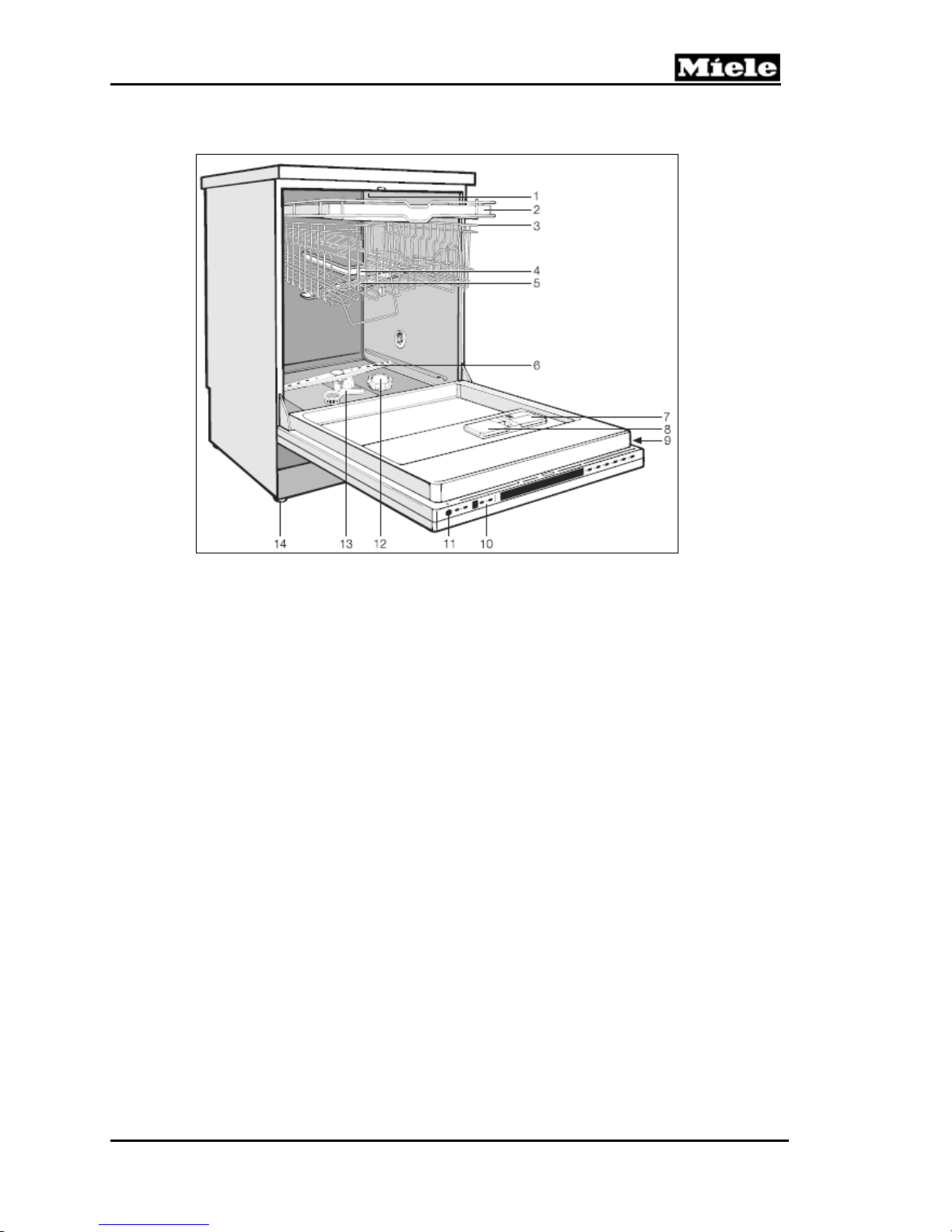
1.1.1 Typical Integrated Model
G 600/G 800
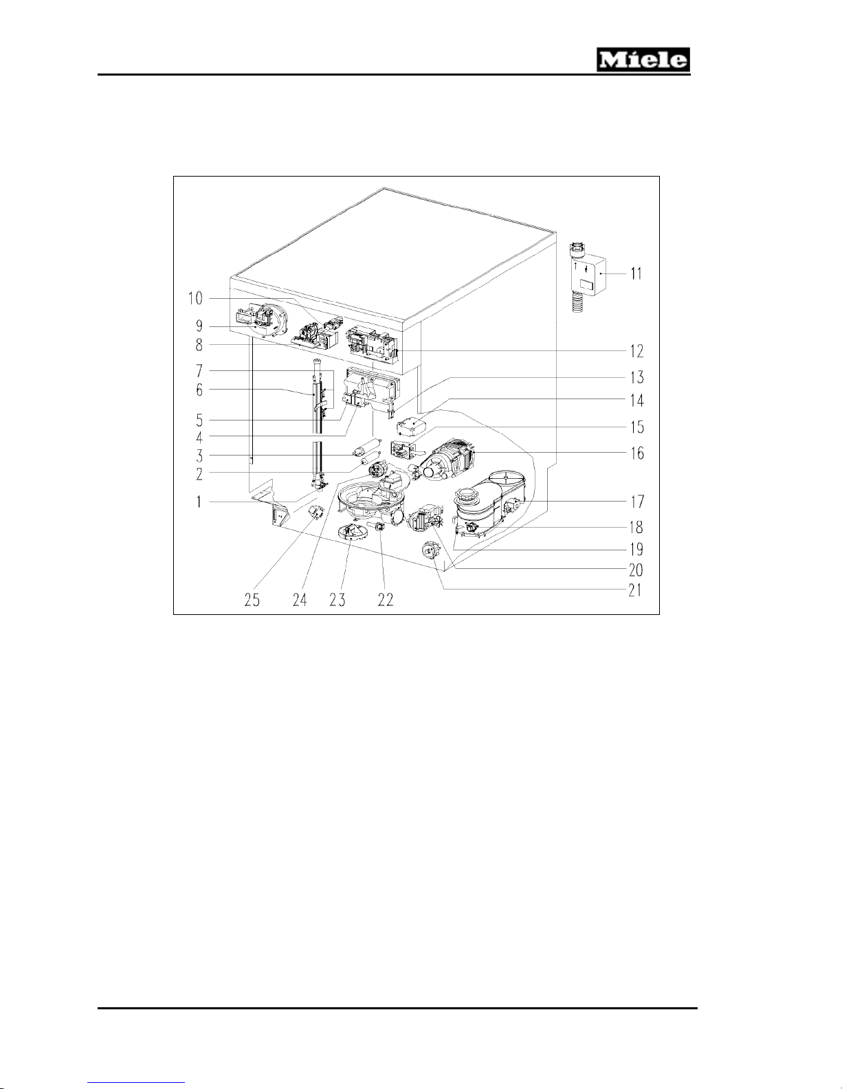
Figure 1-1: Overview of Typical Integrated Model
1
Upper spray arm (not visible)
2
Cutlery tray (model-dependent)
3
Upper basket
4
Water feed for middle spray arm
5
Middle spray arm
6
Water hardness selector (model-dependent)
7
Lower spray arm
8
Four height-adjustable feet
9
Filter combination
10
Salt reservoir (model-dependent)
11
Dual-compartment detergent dispenser
12
Rinse aid reservoir with dosage selector
13
Data tag
12
G 600/G 800
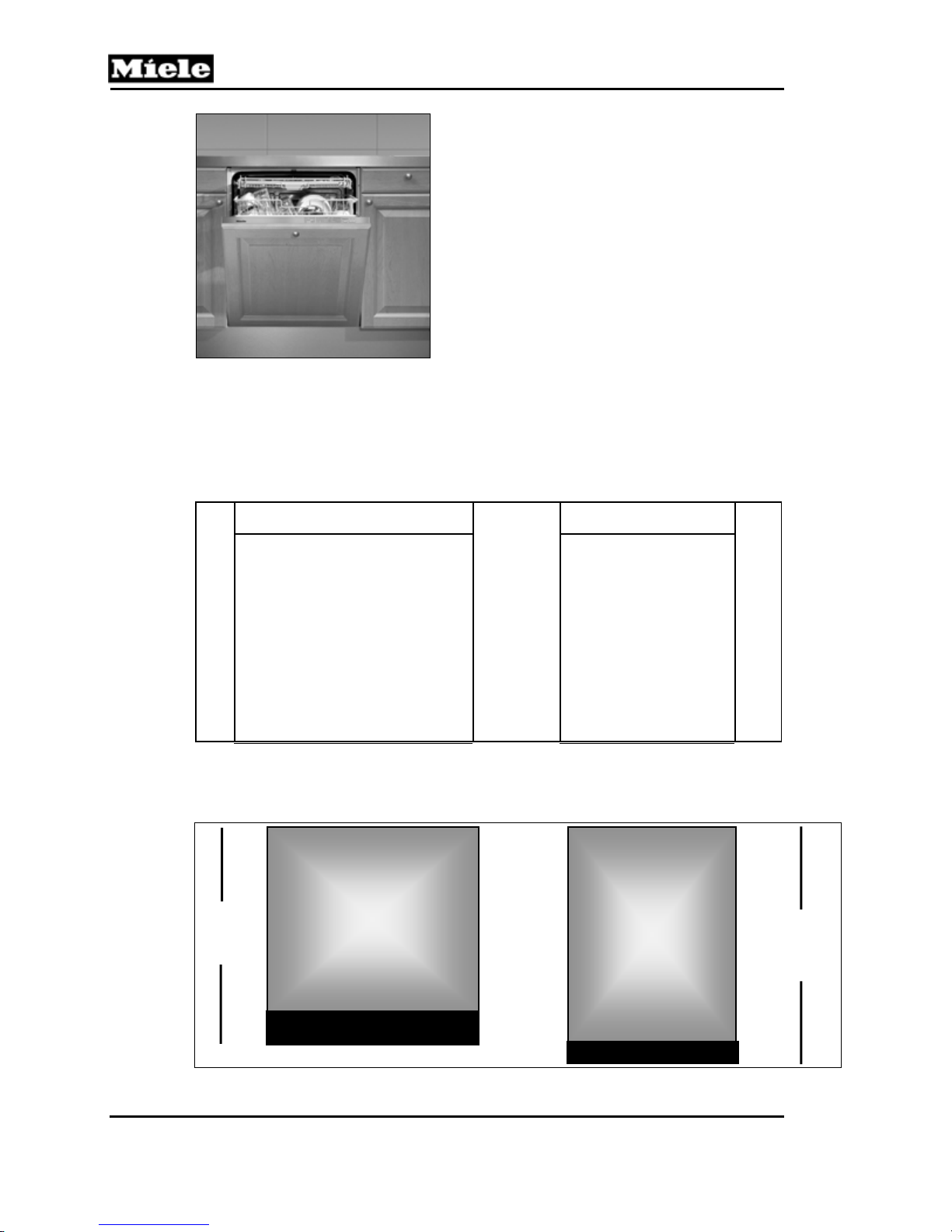
1.1.2 Typical Fully Integrated Model
Technical Information
Figure 1-2: Overview of Typical Fully Integrated Model
1
Upper spray arm (not visible)
2
Cutlery tray (model-dependent)
3
Upper basket
4
Water feed for middle spray arm
5
Middle spray arm
6
Lower spray arm
7
Rinse aid reservoir
1.2 Control Panels
Miele dishwashers are currently categorized into three (3) product series, based on
the type of controls.
1.2.1 Novotronic
Each Novotronic-model dishwasher can be operated with a single knob. Surfacemounted design (SMD) technology allows Miele Novotronic components to be
extremely durable and reliable. These controls are capable of performing hundreds
of tasks which cannot be handled by mechanical components.
8
Detergent dispenser
9
Data tag
10
Control panel
11
Optical interface
12
Salt reservoir
13
Filter combination
14
Height-adjustable feet
13

Technical Information
G 600/G 800
Figure 1-3: Novotronic Control Panel (G 841 Shown)
1.2.2 Touchtronic
This series of Miele dishwashers is operated by pushing a single button – no
separate temperature or drying selections – just turn the machine on, select a
program and Miele does the rest. All models now include a Pots and Pans program
and a Water Management System, designed to maximize cleaning results and
optimize water and energy conservation.
Figure 1-4: Touchtronic Control Panels (G 832 Shown)
1.2.3 Incognito
The Incognito (fully integrated) series dishwashers have the program controls
located on the top edge of the door, which can be accessed while the door is open.
Neither seen nor heard, the Miele Incognito Series OCI (Optical Cycle Indicator)
allows you to see the progress of the dishwasher cycle by way of a red light, which is
steady or flashing depending on the status of the cycle.
Figure 1-5: Incognito Control Panels (G 818 Shown)
1.3 Types of Dishwashers
1.3.1 Pre-Finished
The pre-finished construction consists of a pre-assembled door panel and control
panel, making it an ideal replacement machine. Available in white, black or stainless
steel.
14

G 600/G 800
Technical Information
Figure 1-6: Pre-Finished Dishwasher
1.3.2 Integrated
This type of dishwasher is shipped with a separate control panel and optional GDU
(door) panel. Every integrated dishwasher ships with a bracket for installing a custom
cabinet panel. The use of separate components allows for a truly customized
installation.
Figure 1-7: Integrated Dishwasher
1.3.3 Fully Integrated
Fully integrated (Incognito) dishwashers are designed to blend into the surrounding
cabinetry. The operator controls are only available when the door is opened. Each
dishwasher is shipped with a bracket for securing a custom cabinet panel. An
optional Miele stainless-steel SCVi panel is also available.
15
Technical Information
G 600/G 800
Figure 1-8: Fully Integrated Dishwasher
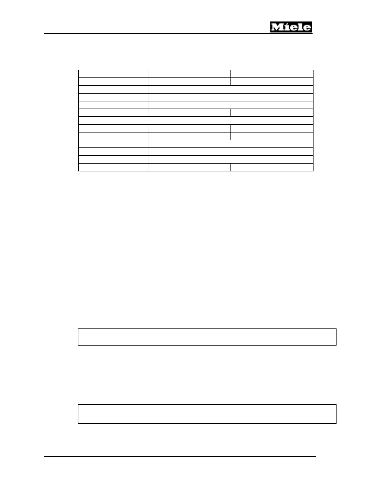
1.4 Technical Data
1.4.1 Dishwasher Width – Full-Size/Slimline
Full-size
23 ½ "
Figure 1-9: Dishwasher Widths
1.4.2 Dishwasher Heights – 600/800 Series
32 ¼”
to
34 ⅞”
600 Series
Slimline
17 ½ "
800 Series
33 ⅛”
to
35”
Figure 1-10: Dishwasher Heights
16
G 600/G 800
1.4.3 Summary of Dimensions
Full-Size G 600 Series G 800 Series
Height 32 ¼“ to 34 ⅞“ 33 ⅛” to 35”
Width of machine 23 ½“
Width of opening 23 ⅝”
Depth 22 ½“
Depth w/door open 45 ½“ 47 ½“
Slimline G 600 Series G 800 Series
Height 32 ¼“ to 34 ⅞“ 33 ⅛” to 35”
Width of machine 17 ½“
Width of opening 17 ¾”
Depth 22 ½“
Depth w/door open 45 ½“ 47 ½“
Table 1-1: Summary of Dimensions
1.4.4 Electrical Information
The appliance is equipped with a 4-foot power cord and molded NEMA 5-15 plug for
connection to a NEMA 5-15R receptacle (120VAC, 15-amp, 3-prong, grounded
outlet).
Technical Information
It is recommended that the power outlet for the appliance be installed on the wall
(within the cabinets), adjacent to under-counter space where the appliance is
installed.
Ensure that the cabinets contain no rough edges that could damage the power cord
or drain hose. If metal cabinets are used, ensure that a rubber grommet is installed
around the opening.
Always exercise caution when sliding the dishwasher in or out, to prevent damaging
the power cord and/or hoses.
1.4.5 Hard-Wired Electrical Connection
Connect L1 (black) to L on the terminal block, N (white) to N on the terminal block,
and GND to the ground connector.
Note:
Hardwiring the dishwasher should only be done if required by electrical code.
Do not cut the plug off the power supply cord/plug and connect it directly to the
house wiring under any circumstances. This voids the warranty.
For hardwiring, the power cord must be removed from the appliance by
disconnecting the cord from the terminal block located at the lower left front of the
dishwasher, behind the toekick and service panel. Feed the permanent power supply
cable through the strain relief and secure it directly to the terminal block.
Note:
The appliance must be grounded.
17
Technical Information
1.4.6 Plumbing Connections
1.4.6.1 Intake Connection
The appliance is supplied with a 5-foot-long Double WaterProof System intake hose,
equipped with a ¾-inch female hose connection for connection to a ¾-inch male
hose thread water supply valve.
1.4.6.2 Drain Connection
The appliance is equipped with a 5-foot-long drain hose for connection to a ¾-inch
drain nipple.
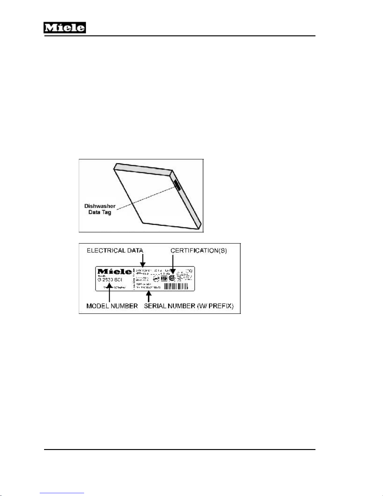
1.5 Data Tag
G 600/G 800
Figure 1-11: Data Tag Location
Figure 1-12: Data Tag Information
18
G 600/G 800
1.6 Layout of Components
1.6.1 Novotronic and Touchtronic Series
Technical Information
Figure 1-13: Component Overview – Novotronic & Touchtronic Series
1
Temperature limiter 90°C, 3F2 (before 8/99)
2
Interference suppression capacitor, Z2
3
Circulation pump capacitor, C6
4
Rinse aid dispenser, Y50
5
Detergent dispenser, Y51
6
Flow-through heater, R1
7
Temperature limiter 150 °C, 1F2 and 2F2
8
Door switch, S24
9
Fan, M2, & PTC release element, Y56
10
On/off switch, S2
11
WaterProof System (WPS), Y2
12
Electronic
13
Rinse aid reed switch, B8/1
14
Heater relay, 1K1/1
15
Terminal block, X3/1
16
Circulation pump, M6
17
Water softener valve, Y38/1
18
Flow meter, B3/4
19
Salt float switch, B8/2
20
Drain pump, M8
21
Overflow level switch, B1/2
22
Temperature sensor, R30
23
Float switch, B8/3
24
Heater pressure switch, B1/10
25
Transformer, T1
19
Technical Information
1.6.2 Incognito Series
G 600/G 800
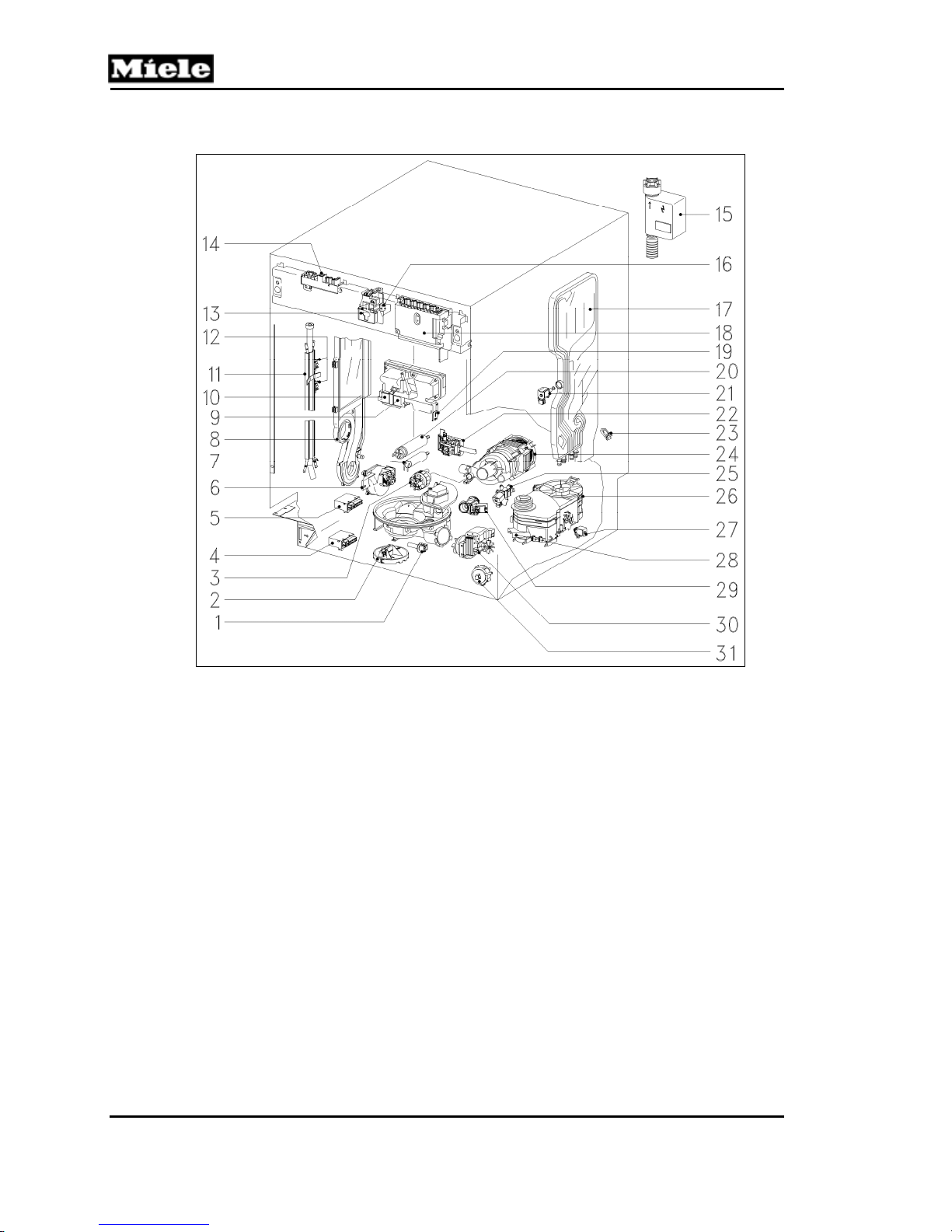
Figure 1-14: Component Overview – Incognito (Vi) Series
1 Temperature sensor, R30 17 Water intake mixer
2 Float switch, B8/3 18 Electronic
3 Heater pressure switch, B1/10 19 Rinse aid reed switch, B8/1
4 Power relay, 1K1/6 20 Circulation pump capacitor, C6
5 Heater relay, 1K1/1 21 Water control valve, Y5
6 Fan, M2 22 Terminal block, X3/1
7 Interference suppression capacitor, Z2 23 Flow meter, B3/4
8 Steam condenser (not all models) 24 Circulation pump, M6
9 Rinse aid dispenser, Y50 25 Condenser control valve, Y6 (if equip. w #8)
10 Detergent dispenser, Y51 26 Water softener (resin tank)
11 Flow-through heater, R1 27 Water softener valve, Y38/1
12 Temperature limiter, 1F2 and 2F2 28 Reactivation salt indicator switch, B8/2
13 Door contact switch, S24 29 Circulation valve, Y27
14 Electronic 30 Drain pump, M8
15 WaterProof System (WPS), Y2 31 Overflow level switch, B1/2
16 Door switch, S5
20
G 600/G 800
2.0 Installation
Refer to the appliance installation manual.
Technical Information
21
Technical Information
G 600/G 800
3.0 Commissioning and Operation
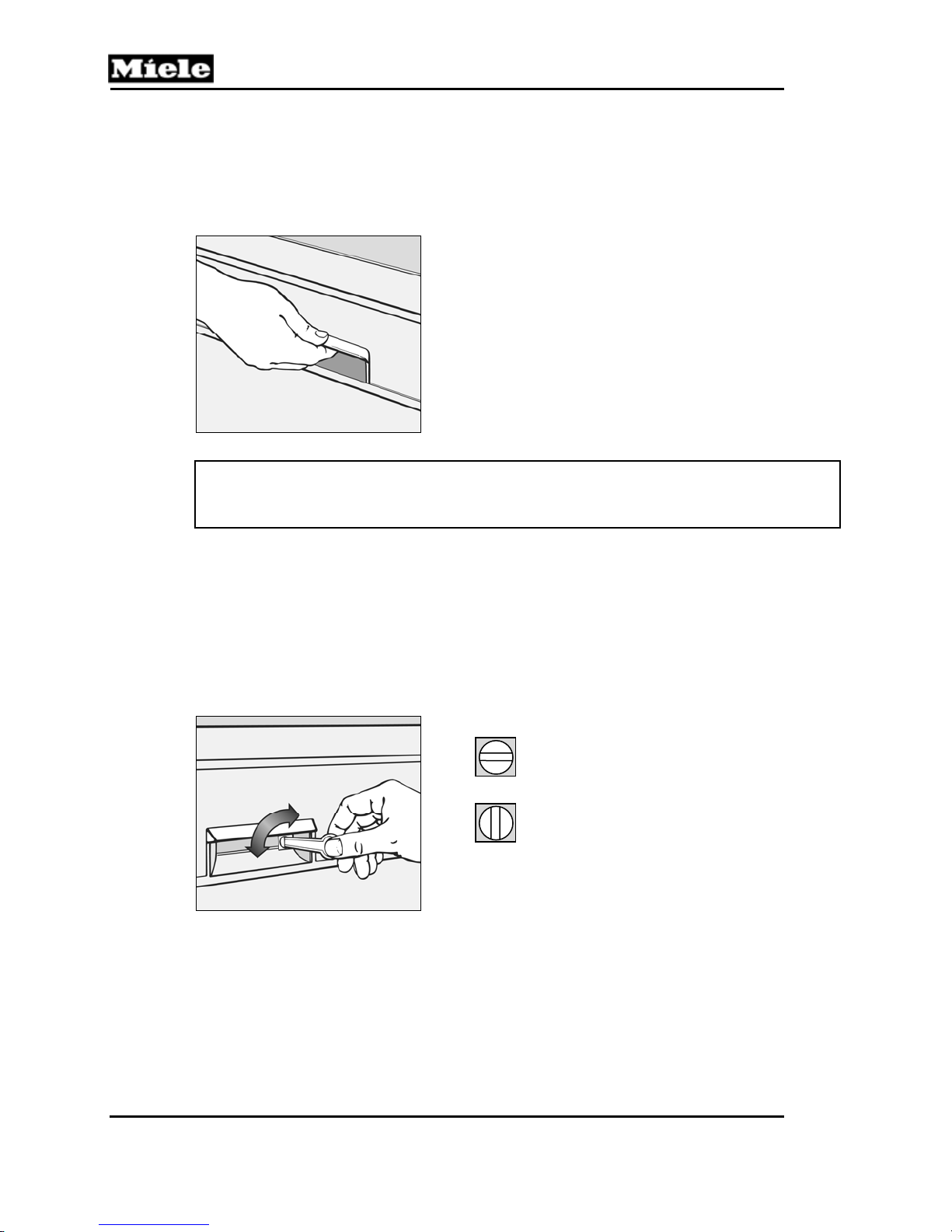
3.1 Door Handle and Door Lock (Novotronic/Touchtronic Series)
Press the release catch inside the door grip.
Figure 3-1: Door Handle and Door Lock (Novotronic/Touchtronic)
Note:
If the door is opened during operation, the dishwasher will stop running. Once the
door is closed the program will restart.
3.2 Closing the Dishwasher Door
To close the door, push the baskets in, then lift the door and push until it clicks into
place.
3.3 Child Safety Lock
Horizontal setting = Door is
locked.
Vertical setting = Door can
be opened.
Figure 3-2: Child Safety Lock
22
G 600/G 800
3.4 Water Softener
If your tap water hardness is above 8 grains per gallon (140 ppm), the water should
be softened.
A water hardness test strip is used to determine the water hardness.
If the water softener is needed:
The dishwasher must be programmed to “with water softener” (ON).
The water softener reservoir is filled with softener salt.
The water hardness level is programmed into the dishwasher electronic.
If the water softener is not needed:
The dishwasher must be programmed to “without water softener” (OFF);
however, the hardness level is not programmed into the electronic.
Salt is not needed and should not be installed.
3.4.1 Water Softener Salt
Only use water softener salt specially formulated for dishwashers. Other salts may
contain insoluble additives which can impair the water softener. The proper salt can
be purchased from the Miele Technical Service department.
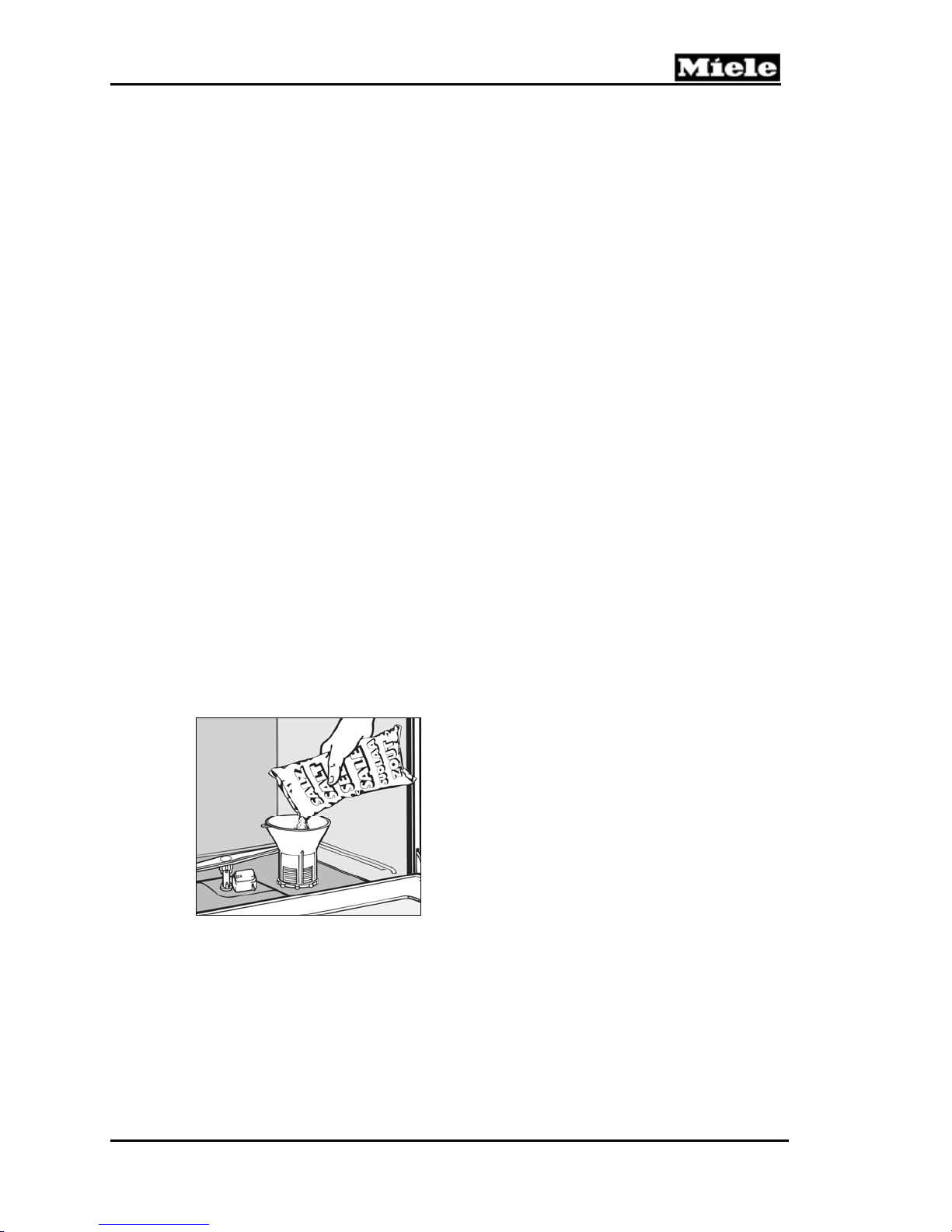
To add salt:
1. Remove the lower basket and unscrew the salt container cap located on the floor
of the wash cabinet.
2. Before adding salt for the first time, fill the salt container with 2 quarts (2 liters)
of water.
3. Place a funnel over the salt container. Carefully fill with salt. See Figure 3-3. The
salt container holds approximately 4.5 pounds (2 kilograms) of salt.
4. Clean any excess salt from the threads of the container opening. Screw the lid on
firmly.
5. Run the Rinse & Hold program to remove any traces of salt from inside the
wash cabinet.
Technical Information
Figure 3-3: Filling the Salt Container
3.5 General Operation
3.5.1 Novotronic Series
1. Make sure that the spray arms are not blocked.
2. Close the door.
3. Turn on the dishwasher. The "Start" indicator will flash.
23
Technical Information
4. Select a wash program by turning the program selector to the left or right.
5. Press the "Start" button.
3.5.2 Touchtronic Series
1. Make sure that the spray arms are not blocked.
2. Close the door.
3. Turn on the dishwasher. The "Start/Stop" indicator will flash and a program
indicator will light.
4. Select a wash program using the program selection buttons. The selected
program indicator will light.
5. Select Top solo, if desired.
6. Press the "Start/Stop" button.
3.5.3 Incognito Series
1. Open the door.
2. Make sure that the spray arms are not blocked.
3. Turn on the dishwasher using the On button.
4. Select a wash program using the program selection buttons.
5. The selected program indicator will light.
6. Close the door. The optical indicator illuminates and the program begins.
G 600/G 800
Note:
For specific program details and further information on operating the dishwasher,
refer to the model-specific operating manual.
4.0 Description of Function
4.1 Cabinet Construction
The inner cabinet is constructed of stainless steel (1.4301) welded onto four (4)
vertical U-section sub-frames. The cabinet is sound and heat-insulated with bitumen
and/or mineral wool matting.
4.2 Fan Assembly (Machines Equipped w/Turbothermic Fan)
The fan assembly consists of the fan motor (M2) and a PTC release element (Y56),
which opens the air outlet flap. The 120VAC fan operates in the drying stage, after a
brief delay. The PTC release element is activated, and the air outlet flap is partially
opened. A bypass channel behind the air outlet is also opened and ensures that the
moist air from the cabinet is mixed with dry air from the door interior. This prevents
condensation from developing. After about a minute, the electronic switches off the
release element, but the air outlet flap remains partially open. After a few minutes,
the release element is activated again, which completely opens the air outlet flap.
The fan operates constantly throughout this period until the program ends. The air
outlet flap remains open at program end and closes when the dishwasher door is
opened.
24
G 600/G 800
Technical Information
4.2.1 PTC Release Element (Machines Equipped w/Turbothermic Fan)
When 120VAC is applied to the release element, the PTC resistor heats a small
grease-filled capsule. As the grease expands, it pushes a piston upward and slides
the air outlet flap to a partially open position. When the release element is activated
the second time, the piston slides the air outlet flap to a fully open position.
4.3 Combination Dispenser
4.3.1 Construction
Two individual solenoids control detergent and rinse aid dispensing.
The rinse aid reservoir has a capacity of about 130mL (4.4 fluid ounces). When the
rinse aid level drops to about 25mL (0.85 fluid ounces), the magnetic float activates a
reed switch on the edge of the dispenser and the rinse aid LED illuminates.
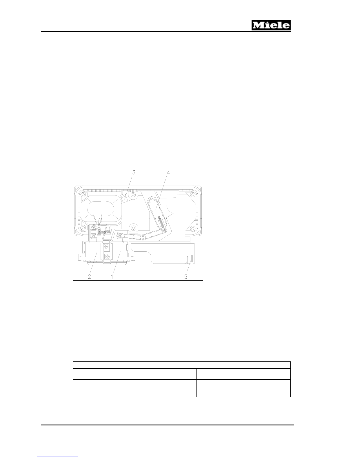
Figure 4-1: Dispenser Assembly
1 Rinse aid solenoid (120VAC), Y50
2 Detergent chamber flap solenoid (120VAC), Y51
3 Hose connection for condensate from fan (fan-equipped models only)
4 Rinse aid dispenser mechanism
5 Reed switch, B8/1
4.3.2 Dispensing
During the main wash, the detergent solenoid (Y51) is energized (120VAC) to open
the detergent dispenser flap. The water jet from the middle spray arm flushes
detergent out of the dispenser.
Model Pre-Wash Compartment (cm3) Main Wash Compartment (cm3)
C2.06 25 80
C2.09 20 70
Table 4-1: Detergent Quantity in Combination Dispensers C2.06 and C2.09
During the final rinse, the rinse aid solenoid (Y50) is energized (120VAC) to open the
Detergent Quantity
25
Technical Information
dispenser chamber and allow rinse aid to be dispensed into the cabinet.
Note:
The rinse aid only flows from the reservoir into the dispenser chamber when the
front door is fully opened at the end of a program.
The quantity taken into the dispenser chamber depends on the dispenser selector
setting.
Dispenser Selector
Setting
Table 4-2: Rinse Aid Dispensing (Combination Dispensers C2.06 and C2.09)
When the rinse aid light turns on, an additional 2 to 5 dispensings (at setting 2)
remain available.
Note:
To allow proper filling of the rinse aid dispenser, rinse aid should only be added with
the door in the fully open position.
4.4 Heaters
During the main wash and final rinse portions of a wash cycle, the water is heated to
the program’s specified temperature before advancing to the next step in the
program (e.g., Thermal Stop).
G 600/G 800
Rinse Aid Quantity
Rated Quantity (mL) Lower Limit (mL) Upper Limit (mL)
1 1 0.8 1.8
2 2 1.8 2.8
3 3 2.8 3.8
4 4 3.8 4.8
5 5 4.5 5.5
6 6 4.5 7.0
The water is heated using one of two systems (cavity-style or flow-through).
4.4.1 Wash Cavity Heater Element
Figure 4-2: Cavity-Style Heater Element
The heater element is mounted just off the floor of the wash cavity. When powered
(120VAC), the element radiates heat, thereby heating the surrounding and circulating
water. The temperature of the water is monitored by the temperature sensor
26
G 600/G 800
mounted in the sump.
Heater element switching is performed by the electronic via a relay. The relay (when
energized) closes contacts to provide the heater element with 120VAC. A
temperature limiter mounted with the element provides protection by opening up the
circuit should the temperature become too high.
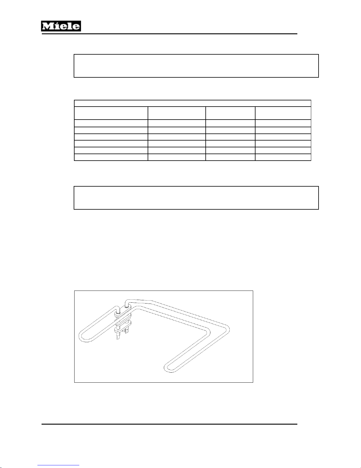
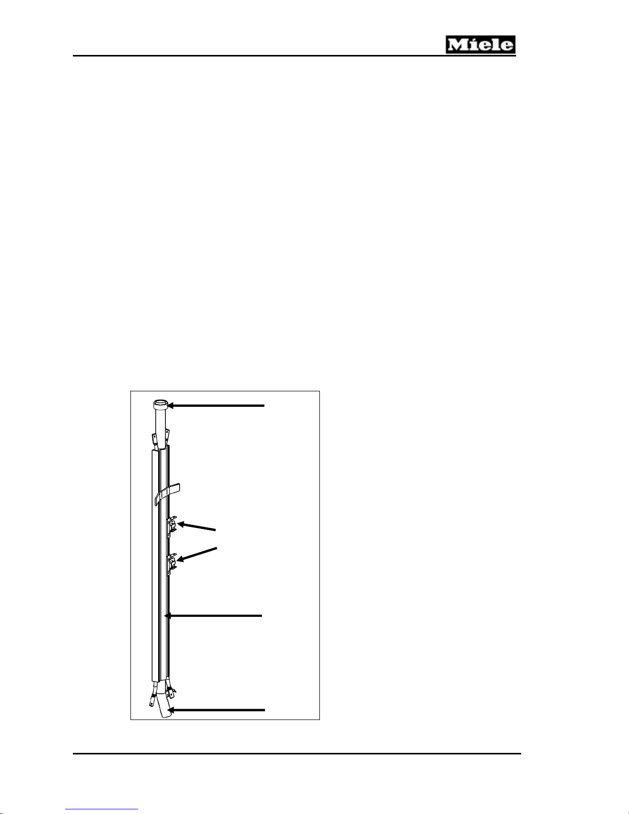
4.4.2 Flow-Through Heater
The flow-through heater assembly is mounted on the (left side) exterior of the wash
cabinet. The flow-through heater is plumbed into the water path between the
circulation pump output and the middle spray arm.
The flow-through heater consists of a heater element mounted parallel to a metal
tube that water passes through when the dishwasher is circulating.
As water flows through the metal tube, the water is heated and exits through the
middle spray arm. As the water falls to the bottom of the wash cavity, it passes
through the filter and re-enters the circulation pump; the process then repeats. The
temperature sensor monitors the water temperature until the program’s specified
temperature is reached. Generally, the water heats at a rate of about 20 degrees per
minute.
Heater element switching is performed by the electronic via a relay. The relay (when
energized) closes contacts to provide the heater element with 120VAC. Two
temperature limiters are mounted along the element and provide protection by
opening up the circuit should the temperature become too high.
Technical Information
2
1
1 Water output to middle spray arm
2 Thermal limiters (safety cutouts)
3 Heater element (120VAC)
4 Water intake from circulation pump
3
Figure 4-3: Flow-Through Heater Element
4
27
Technical Information
Voltage
Output power
Rated load
Table 4-3: Flow-Through Heater Electrical Data
120VAC
1.5kW
9.6kΩ
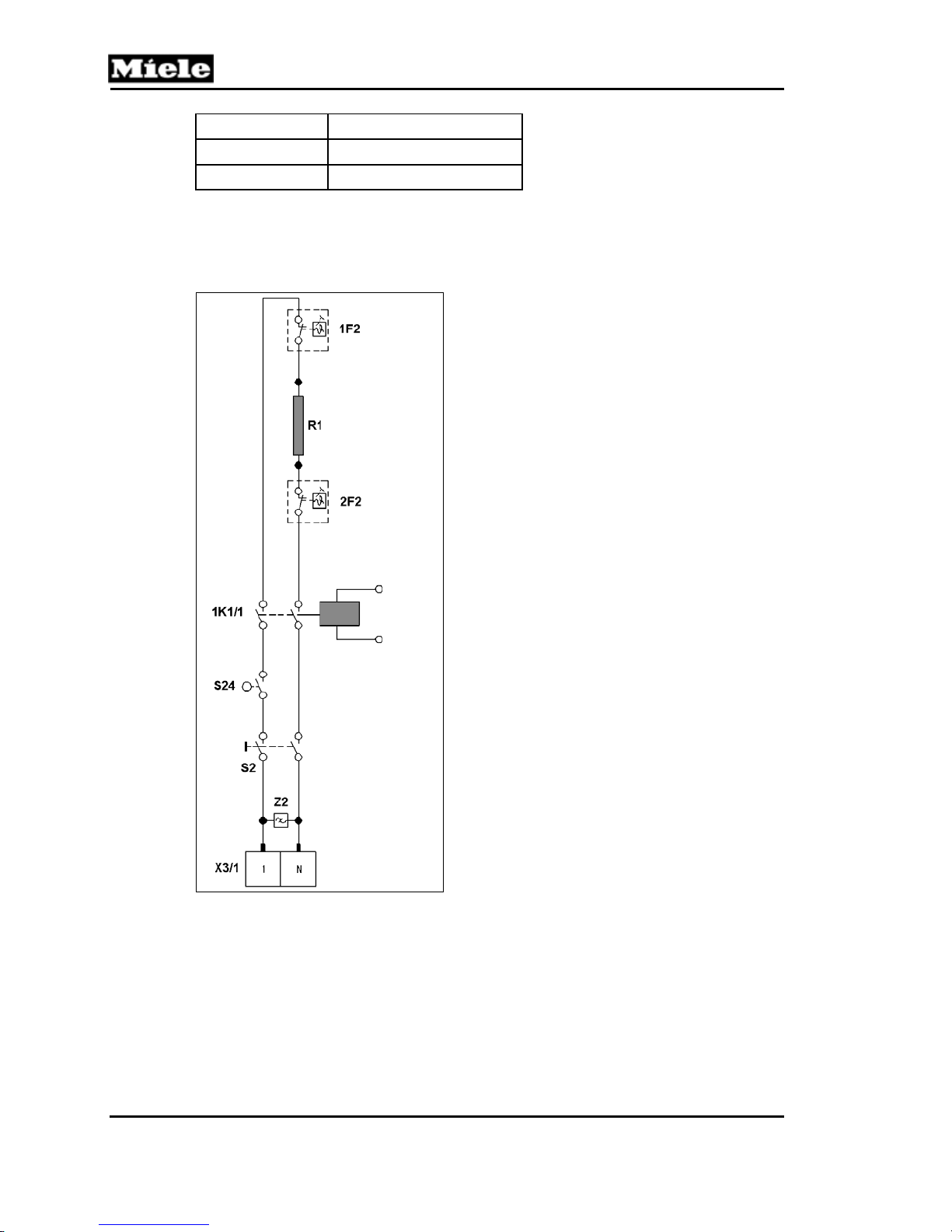
4.5 Heater Circuit Operation
G 600/G 800
Figure 4-4: Heater Circuit
4.6 Pulsed Heating – Operation
In certain programs, heating may be operated at full power until a water temperature
of 77°F is reached, after which power is applied in pulses. This extends the heating
time and allows enzyme-containing detergents to develop their full cleaning potential.
Pulsed heating operates as follows:
1 minute heater element on.
28
G 600/G 800
1 minute heater element off.
The number of pulse cycles is limited to a maximum of 11. If the program’s specified
temperature has not been reached, heating will resume using full power. Once the
program’s temperature has been reached, the electronic advances to the next step in
the program. If the temperature cannot be reached (e.g., heater failure) within a
specified time, the program will advance but a heating fault will be stored in the
electronic.
4.7 Temperature Protection
The two (2) temperature limiters (1F2 and 2F2) mounted on the body of the flowthrough heater are designed to open the heater circuit should the temperature
become too high. When the temperature drops back to normal, the temperature
limiters will not reset automatically and must be reset manually (via the red button on
the back of the heater).
Additional protection is provided by the electronic, which switches the appliance off
and stores an F4 fault code should the temperature exceed 194°F (90°C) as
determined by the temperature sensor.
4.8 Static Drying
The static drying system uses no electrical or mechanical components to assist in
drying. With this system the final rinse water is heated to 154°F (68°C), not the usual
150°F (67°C). The dishwasher cabinet is made of stainless steel and conducts the
heat generated during the final rinse. As the final rinse ends, this stored thermal
energy radiates and assists in drying.
4.9 Spray Arms
The circulation pump (M6) moves the wash water from the sump through the filter
assembly and to the spray arms. The water pressure creates a propulsion effect,
which causes the spray arms to rotate.
Technical Information
Top spray arm 30 to 55 rpm
Middle spray arm 16 to 40 rpm
Bottom spray arm 24 to 50 rpm
Table 4-4: Spray Arm Rotation Speeds
4.10 Filter Assembly
Circulating wash water is filtered via 2 parallel paths. A portion of the water flows
through the center opening of the coarse filter and passes through the microfine
filter. The remaining water passes through the large surface area fine filter. The
coarse filter is attached to the filter combination handle. If dispensed powder
detergent should fall into the microfine filter, it will remain on the filter cap where it
can dissolve, instead of collecting in the drain outlet. Foreign objects which pass the
coarse filter to the microfine filter collect on the filter cap so they won’t clog the drain
outlet.
29
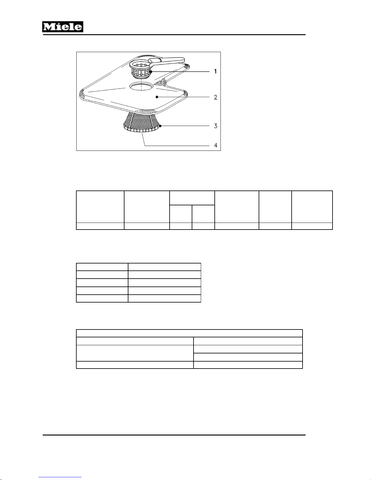
Technical Information
G 600/G 800
1 Coarse filter/handle
2 Large surface area fine filter
3 Microfine filter
4 Filter cap
Figure 4-5: Filter Assembly
4.11 Water Intake – Technical Data
Solenoid valve
electrical
connection
120VAC (60Hz) 14.5 - 145 1.3 1.1 5 feet (1.5m) ¾” hose 2” x 4”
Flow pressure
(psi)
Table 4-5: WaterProof System Data
1
The standard WaterProof system can be exchanged for a 15-foot (4.5m) version. With
dishwashers from index 24 (additional seal under both solenoid valves), a 5’ (1.5m) metal hose
can be connected to the WPS valve as an extension.
Restrictor color Flow rate
Green
Gray
White 1.4 gal/min (5.25L/min)
Blue 1.6 gal/min (6.0L/min)
1.1 gal/min (4.1L/min)1
1.3 gal/min (4.9L/min)2
Table 4-6: Flow Restrictor Data
1
Standard with 45cm (Slimline) models
2
Standard with 60cm (full-size) models
Flow rate
(gal/min)
60cm
model
model
45cm
Connection
lead length
1
Threaded
union
Cutout
dimensions
for valve
assembly
housing
Wash water hardness solenoid valve (Y5)
Softener reactivation reservoir capacity
Flow meter Approx. 200-220 pulses/liter
Table 4-7: Water Inlet Mixer Data
4.12 WaterProof System (WPS)
The water inlet valve (Y2) consists of two (2) electromechanical valves mounted
within a waterproof box located at the water connection (end of the water intake
hose).
Water Inlet Mixer
120VAC 60Hz
13.5 fl.oz. (400mL) for 60cm model
11.5 fl.oz. (340mL) for 45cm model
30
 Loading...