


Operating instructions
for cooker hood
DA 68, DA 68 EXT
It is essential to read these
operating instructions before
installing or using the machine,
to avoid the risk of accident
or damage to the machine. M.-Nr. 05 035 290
Q\}

Contents
Contents
Caring for the environment . . . . . . . . . . . . . . . . . . . . . . . . . . . . . . . . . . . . . . . . . . 3
Warning and safety instructions . . . . . . . . . . . . . . . . . . . . . . . . . . . . . . . . . . . . . 4
Description of the appliance . . . . . . . . . . . . . . . . . . . . . . . . . . . . . . . . . . . . . . . . . 8
Operation
Notes on the switches . . . . . . . . . . . . . . . . . . . . . . . . . . . . . . . . . . . . . . . . . . . . . . . 9
Selecting the power level. . . . . . . . . . . . . . . . . . . . . . . . . . . . . . . . . . . . . . . . . . . . . 9
Switching the lighting on and off . . . . . . . . . . . . . . . . . . . . . . . . . . . . . . . . . . . . . . . 9
Description of the functions . . . . . . . . . . . . . . . . . . . . . . . . . . . . . . . . . . . . . . . . 10
Cleaning and care
Housing . . . . . . . . . . . . . . . . . . . . . . . . . . . . . . . . . . . . . . . . . . . . . . . . . . . . . . . . . 11
Grease filter . . . . . . . . . . . . . . . . . . . . . . . . . . . . . . . . . . . . . . . . . . . . . . . . . . . . . . 11
Active charcoal filters. . . . . . . . . . . . . . . . . . . . . . . . . . . . . . . . . . . . . . . . . . . . . . . 12
Changing the ’compact’ light or starter . . . . . . . . . . . . . . . . . . . . . . . . . . . . . . . . . 13
After sales service . . . . . . . . . . . . . . . . . . . . . . . . . . . . . . . . . . . . . . . . . . . . . . . . 14
Electrical connection. . . . . . . . . . . . . . . . . . . . . . . . . . . . . . . . . . . . . . . . . . . . . . 15
Technical data . . . . . . . . . . . . . . . . . . . . . . . . . . . . . . . . . . . . . . . . . . . . . . . . . . . . 16
Appliance dimensions . . . . . . . . . . . . . . . . . . . . . . . . . . . . . . . . . . . . . . . . . . . . . 17
Installation
Fitting the non-return cap. . . . . . . . . . . . . . . . . . . . . . . . . . . . . . . . . . . . . . . . . . . . 18
Fitting the adaptor . . . . . . . . . . . . . . . . . . . . . . . . . . . . . . . . . . . . . . . . . . . . . . . . . 18
Building in . . . . . . . . . . . . . . . . . . . . . . . . . . . . . . . . . . . . . . . . . . . . . . . . . . . . . . . 19
Removing the appliance . . . . . . . . . . . . . . . . . . . . . . . . . . . . . . . . . . . . . . . . . . . . 19
Connection for air extraction . . . . . . . . . . . . . . . . . . . . . . . . . . . . . . . . . . . . . . . 20
Connection for air recirculation . . . . . . . . . . . . . . . . . . . . . . . . . . . . . . . . . . . . . 22
Connection to an external fan. . . . . . . . . . . . . . . . . . . . . . . . . . . . . . . . . . . . . . . 23

Caring for the environment
Disposal of packing material
The transport and protective packing
has been selected from materials
which are environmentally friendly for
disposal and can normally be recycled.
Rather than just throwing these materials away, please ensure they are offered for recycling.
Caring for the environment
Disposal of your old appliance
Old appliances contain materials which
can be reclaimed or recycled. Please
contact your dealer, your waste collection centre or scrap merchant about
potential recycling schemes.
Ensure that the appliance presents no
danger to children while being stored
for disposal. See the appropriate section in the Warning and Safety instructions.
3
Warning and safety instructions
Warning and safety instructions
This appliance meets statutory
safety requirements. Inappropriate
use could, however, lead to risk of
accidents to the user and damage
to the appliance.
Read the operating instructions before using this machine for the first
time. They contain important information about the safety, use and
maintenance of the machine. This
will avoid the risk of accidents and
damage to the machine.
Keep these operating instructions in
a safe place and ensure that new
users are familiar with the content.
Pass them on to any future owner of
the machine.
Appropriate use of the cooker
hood
The appliance is intended for do-
mestic use only.
The manufacturer cannot be held responsible for any damage caused by
improper use or by non-observance of
these instructions.
Technical safety
sure that the voltage and frequency details given on the data plate correspond with the on-site electricity supply. If in doubt consult a qualified
electrician.
when continuity is complete between
the appliance and an effective earthing
system which complies with local and
national regulations. It is most important that this basic safety requirement is
tested by a qualified electrician. The
manufacturer cannot be held responsible for the consequences of an inadequate earthing system (eg electric
shock).
qualified and competent persons to ensure safety. No responsibility can be
taken by the manufacturer for repairs
and other work by unqualified persons
which could be dangerous.
Before connecting the cooker
hood to the mains supply, make
The electrical safety of this appliance can only be guaranteed
Installation work and repairs may
only be carried out by suitably
4
Warning and safety instructions
The appliance is only completely
isolated from the electricity supply
when, depending on the type of connection:
- it is switched off at the fused unit or
the fuse is withdrawn
– it is switched off at the wall socket
and the plug removed
To remove the plug, pull on the plug itself, not the cable.
– the mains fuse is withdrawn
– or the screw-out fuse is removed (in
countries where this is applicable).
Ensure current is not restored to the appliance while maintenance or repair
work is being carried out.
Do not connect the appliance to
the mains electricity supply by an
extension lead. Extension leads do not
guarantee the required safety of the appliance (eg danger of overheating).
Use of the appliance
Never use an open flame beneath
the cooker hood. To avoid the
danger of fire, do not flambé or grill
dishes.
When switched on the cooker hood
could draw flames into the filter. Fat
particles drawn into the cooker hood
present a fire hazard.
When using the cooker hood over
a gas hob ensure that any burners
in use are always covered by a pan,
otherwise flames could be drawn up by
the suction of the cooker hood, parts of
which could then be damaged.
Always switch the cooker hood on
when a cooking zone is in use,
otherwise condensation may collect in
the hood, which could cause corrosion.
When cooking with oil or fat, chip
pans and deep fat fryers etc, do
not leave the pans unattended.
Overheated oil and fat can ignite and
could set the cooker hood on fire.
Do not use the cooker hood with-
out the grease filter in place.
This way you will avoid the risk of
grease and dirt getting into the appliance and hindering its smooth operation.
5
Warning and safety instructions
The filters should be regularly
cleaned, or changed, as appropriate.
Saturated filters are a fire hazard.
Under no circumstances use a
steam cleaner to clean this appliance.
Pressurised steam could give rise to a
short circuit or cause permanent damage to the surface and components, for
which the manufacturer of the cooker
hood cannot accept any responsibility.
In countries where there are areas
which may be subject to infestation by cockroaches or other vermin,
pay particular attention to keeping the
appliance and its surroundings in a
clean condition at all times. Any damage which may be caused by cockroaches or other vermin will not be
covered by the appliance guarantee.
Installation
The distance between the top of
the hob and the bottom of the
cooker hood must measure at least:
The distance of 65 cm between
the cooker hood and a gas hob is
a minimum, which is only permissible if
the nominal heat ratings given in the following table are not exceeded:
Gas cooker maximum
nominal rating
one burner 2.7 kW
all burners 7.5 kW
oven 3.5 kW
Gas hob maximum
nominal rating
one burner 3.5 kW
all burners 10.3 kW
Gas hob with ceramic cover plate
The data given for the maximum nominal (heat)
ratings do not apply to a gas hob with a ceramic
cover plate. In this case it is essential to refer to
the hob manufacturer’s data.
Safety regulations prohibit the fit-
ting of a cooker hood over solid
fuel stoves.
All ducting, pipework and fittings
must be of non-flammable material. These can be obtained from the
Miele Spare Parts department or from
builders’ merchants.
– 45 cm above electric hobs
– 65 cm above gas hobs
6
The appliance must not be con-
nected to a chimney or vent flue
which is in use. Neither should it be
connected to ducting which ventilates
rooms with fireplaces.
If exhaust air is to be extracted into
a chimney or ventilation duct no
longer used for other purposes, take
professional advice.
Warning and safety instructions
When using the cooker hood at the
same time as another heating appliance which depends on the air in the
room (eg gas, oil or coal fired heaters,
continuous flow or other water heaters,
gas cooker, gas hob or gas oven), special care must be taken as the action of
the cooker hood extracts air from the
room, which these type of heaters need
for combustion.
In order to ensure safe operation, and to
prevent gases given off by the heating
appliances from being drawn back into
the room when the extractor and the
heater are in operation simultaneously,
an underpressure in the room of 0.04
mbar (4pa) is the maximum permissible.
Ventilation can be maintained by air inlets which cannot be blocked, in windows, doors and outside wall vents, or
by other technical measures, such as ensuring that the extractor can only be
switched on when the heating appliance
is switched off or vice-versa.
Only for appliances with external
fans
For appliances with an external fan
motor fitted (EXT models) the connection of the two units must be made
using the connection cable and the
plug connectors. Make sure the correct combination of the two appliances
has been selected.
Disposal of your old appliance
Ensure that disconnection from the
mains supply is carried out by a
competent person. Render any plug
useless. Cut off the cable directly behind the appliance to prevent misuse.
The manufacturer cannot be held responsible for damage caused by
non-observance of these instructions.
NB: The overall ventilation condition of
the dwelling must be taken into account. If in any doubt, the advice of a
competent builder or, for gas, a “Corgi”
installer must be sought.
If the cooker hood is operated in recirculation mode only, with active charcoal filters, these restrictions do not
apply.
7
Description of the appliance
Description of the appliance
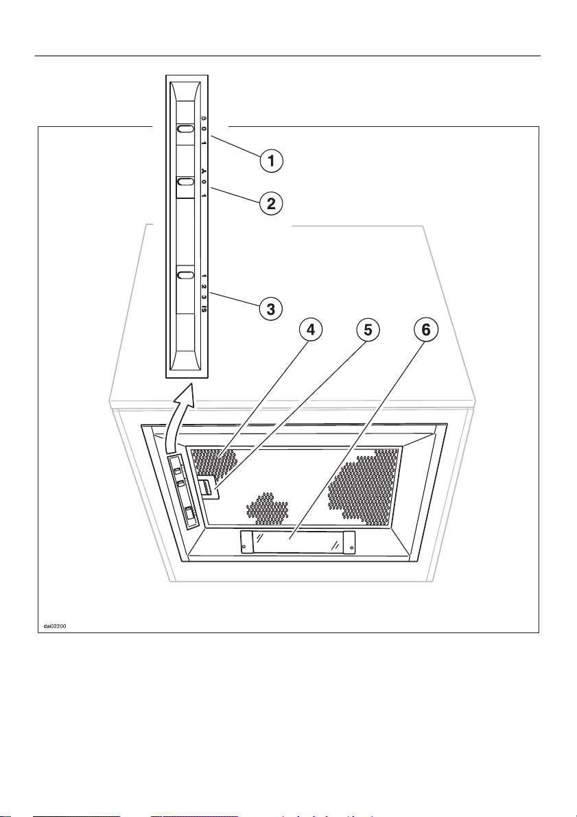
Sliding switch for hob
b
lighting
Sliding switch for the fan
c
Sliding switch for the
d
power setting
8
Grease filter
e
Grease filter retaining clip
f
Lighting for hob
g

Operation
Notes on the switches
The sliding switch b turns the hob
lighting on and off.
The sliding switch
and off.
The sliding switch
four power settings available (1 = low).
turns the fan on
c
selects one of the
d
Operation
Switching the lighting on and
off
The hob lighting can be switched on
and off independently of the fan.
Set the sliding switch for the hob
lighting at:
–”0“ to switch the lighting off
Selecting the power level
The sliding switch d can be used to
select one of four power levels available depending on how much the air
needs to be filtered. For normal cooking a low to medium level is usually
enough. For frying or cooking food with
a strong aroma the “IS” intensive level
is recommended.
To operate
Set the sliding switch for the fan at
”1“.
After cooking
If the air still needs to be cleared after
cooking, we recommend letting the
cooker hood continue to run for a further ten minutes.
To switch off:
Set the sliding switch for the fan at
”0“.
–”1“ to switch the lighting on.
9

Description of the functions
Description of the functions
Before installation choose whether the
cooker hood is to work in extraction or
recirculation mode.
Air extraction
In air extraction mode the air is drawn
in and cleaned by the grease filter and
directed outside.
The cooker hood is fitted with a non-re-
turn flap (see section on "Installation").
This flap is closed when the cooker
hood is switched off. No exchange of
room air and outside air can take
place. When the cooker hood is
switched on the non-return flap opens
for the cooking smells to be blown directly outside.
Air recirculation
The air is drawn in and cleaned first by
the grease filter. In addition it is then
cleaned by the two active charcoal filters. The cleaned air is then recirculated back into the kitchen through a
vent in the top of the cooker hood.
External fan
The ...EXT models of cooker hoods are
designed to be connected with an ex-
ternal fan.
The external fan is connected to the
cooker hood by means of a control
cable and is operated by the control
panel on the cooker hood.
Before using the cooker hood for
the first time, ensure that the active
charcoal filters are in place, see section on “Cleaning and care”.
10

Cleaning and care
Before carrying out maintenance
work, the cooker hood must be disconnected from the mains supply.
Ensure that, depending on the connection:
- it is switched off at the fused unit
or the fuse is withdrawn, or
- it is switched off at the wall socket
and the plug removed (do not pull
on the cable, only on the plug), or
- the mains fuse is withdrawn; or
- the screw-out fuse is removed (in
countries where this is applicable).
Ensure curent is not restored to the
appliance while maintenance or repair work is being carried out.
Housing
The cooker hood housing can be
cleaned using warm water to which a
little mild detergent has been added.
Dry using a soft cloth.
Cleaning and care
Grease filter
The re-usable metal grease filter in the
appliance removes solid particles from
the kitchen vapours (grease, dust, etc)
preventing soiling of the cooker hood.
Clean the grease filter when it looks
dirty, and avoid letting it become so
dirty that the filtering effect is inefficient.
The grease filters should be cleaned
regularly, at least every 3 or 4 weeks. to
avoid a build-up of fat.
An oversaturated filter is a fire hazard.
Never use cleaning agents containing soda, acids, chlorides or abrasive substances, as these can
damage the surface material.
To remove the grease filter, push the
filter retention clip in towards the
middle.
Remove the filter downwards, taking
care not to let it fall on to the hob
below.
11

Cleaning and care
Clean the filter –
– By hand: with a scrubbing brush in
hot water with detergent.
– in a dishwasher: Place the grease fil-
ter with the short side upright in the
lower basket, ensuring the spray
arm is not obstructed.
Depending on the cleaning agent
used, cleaning the grease filter in a
dishwasher can cause permanent
discoloration of the surface of the filter.
However, this will not affect the functioning of the grease filter in any
way.
After cleaning leave the filter to dry
for a while on an absorbent surface
before putting it back in place.
When removing the filters for cleaning also clean off any residues of oil
or fat from the now accessible housing to prevent the risk of these catching fire.
When putting the grease filter back
ensure that the retention clip faces towards the hob.
Should the filter be replaced upside
down, insert a small screwdriver
blade into the slits to disengage the
clip. Do not let the filter fall on to the
hob below.
Active charcoal filters
If the cooker hood is connected for air
recirculation, two active charcoal filters
must be installed in addition to the
grease filter. These filters absorb
odours from the kitchen.
Remove the grease filter.
Remove the packaging of the active
charcoal filters.
Secure the active charcoal filters
using the screws enclosed.
The active charcoal filters should be replaced when they are no longer functioning efficiently, or at least every six
months
Put the grease filter back in place.
12

Changing the ’compact’ light
or starter
If the lighting is not working the ’com-
pact’ light and/or starter may need to
be changed.
Disconnect the cooker hood from
the mains supply. Ensure that, depending on the connection:
- it is switched off at the fused unit
or the fuse is withdrawn, or
- it is switched off at the wall socket
and the plug removed (do not pull
on the cable, only on the plug), or
- the mains fuse is withdrawn; or
- the screw-out fuse is removed (in
countries where this is applicable).
Ensure curent is not restored to the
appliance while maintenance or repair work is being carried out.
Cleaning and care
Carefully swivel the light tube out of
the bracket downwards and pull out
to the left from its retainer.
Change the ’compact’ light (18 W) or
the starter.
Unscrew the fixing screws on the
glass cover holders.
When doing this, push the glass
cover upwards so that it does not fall
on the hob surface.
Take off the glass cover holders.
Take out the glass cover, guiding it
downwards at an angle.
Clip the new ’compact’ light into the
bracket and then carefully slide sideways into the retainer.
Put the glass cover back into place
and secure with the glass cover
holders.
13

After sales service
After sales service
In the event of any faults which you cannot easily remedy, please contact:
– Your Dealer
or
– Your nearest Service Dept,
(see address on the back page).
When contacting the Service Department, please quote the Model and Serial number of your machine / appliance,
both of which are given on the data
plate which is visible on removing the
grease filter(s).
14

Electrical connection
Electrical connection
Electrical connection
All electrical work should only be undertaken by a suitably competent person
in strict accordance with national and
local safety regulations.
The data plate gives the necessary
data for connection. This is visible
when the rear grease filter has been
removed.
The cooker hood is supplied for connection to a 220-230 V single phase
50 Hz supply.
Connection should be made either by a
double pole fused spur connection
unit, or a fused plug and switched
socket. The On-Off switch should be
easily accessible after the appliance
has been built in. For extra safety it is
advisable to install a residual current
device (RCD) with a trip current of 30
mA.
Important
The wires in the mains lead are coloured in accordance with the following
code:
Green/yellow = earth
Blue = neutral
Brown = live.
If the appliance is to be connected via
a plug and socket, please note the following:
As the colours of the wires in the mains
lead of this appliance may not correspond with the coloured markings identifying the terminals in your plug, proceed as follows:
The wire which is coloured green and
yellow must be connected to the termi-
nal in the plug which is marked with the
letter E or by the earth symbol z or coloured green or green and yellow.
The wire which is coloured blue must
be connected to the terminal which is
marked with the letter N or coloured
black.
The wire which is coloured brown must
be connected to the terminal which is
marked with the letter L or coloured red.
WARNING:
THIS APPLIANCE MUST BE
EARTHED
Non-rewireable plugs BS 1363 (UK)
If this machine or appliance is fitted
with a non-rewireable plug, the following information applies:
If the socket outlets are not suitable for
the plug supplied with this product, it
must be cut off and an appropriate
plug fitted. The plug cut from the flexible cord should be disposed of, and
on no account be inserted into any
socket elsewhere in the house (electric
shock hazard).
The fuse cover must be re-fitted when
changing the fuse and if the fuse cover
is lost the plug must not be used until a
suitable replacement is obtained.
The colour of the correct replacement
cover is that of the coloured insert in
the base of the plug (as applicable to
the design of plug fitted).
The correct fuse rating of the replacement fuses that are ASTA approved to
BS 1362 should be fitted. Replacement
fuse covers may be purchased from
your local electrical suppliers or Service agent.
15

Electrical connection
Technical data
Rated load . . . . . . . . . . . . . . . . . 258 W
Lighting . . . . . . . . . . . . . . . . . . . 18 Wt
Voltage . . . . . . . . . . . . . . . . . 220-230 V
Frequency . . . . . . . . . . . . . . . . ~ 50 Hz
Fuse rating (GB). . . . . . . . . . . . . . 13 A
Fuse rating (IRL,ZA). . . . . . . . . . . 10 A
Connection cable. . . . . . . . . . . . 1.5 m
Fan power
– Air extraction system ø 125 mm:
Air extraction according to DIN
44971
3
Extraction, Level 1–3 . . . 190–390 m
Level IS . . . . . . . . 500 m
Recirculation, Level 1–3. 160–255 m
Level IS . . . . . . 300 m
unrestricted, Level 1–3. . 230–410 m
Level IS . . . . . . . 540 m
/h
3
/h
3
/h
3
/h
3
/h
3
/h
16

Appliance dimensions
Appliance dimensions
17

Installation
Installation
Safety regulations prohibit the fitting
of this cooker hood over a solid fuel
stove.
The following minimum distances
must be maintained between the
cooker hood and the hob:
– 45 cm for electric hobs
– 65 cm for gas hobs (see also
Warning and Safety section).
A distance of 65 cm above electric
hobs may be preferable to give more
working space.
Fitting the non-return flap
(for air extraction mode only;
not for ...EXT models)
Fitting the adaptor
(not for ...EXT models)
Take the largest adaptor possible.
The larger the diameter - the higher
the exhaust suction and the quieter
the running noise.
Locate the non-return flap in the exhaust socket so that you can open
the flaps upwards.
Turn the non-return flap slightly anticlockwise to secure it.
18
Put one of the adaptors supplied
(ø100 mm or ø120/125 mm) on the
exhaust socket and turn anti-clockwise to connect the adaptor firmly
with the exhaust socket.

Installation
Building in
The cooker hood is intended to be builtinto a cooker hood housing unit.
Cut-out size: 500 x 340 mm.
Place the appliance in the cut-out
from below and align.
Removing the appliance
Disconnect the cooker hood from the
electricity supply by removing the
plug and with EXT models, removing
the connector for the lead to the external fan.
Remove the extraction ducting from
the exhaust stub.
Unscrew the fixing screws and
remove the cooker hood from beneath.
Secure the cooker hood to the housing unit with the fixing screws.
Carry out the further connection for
air extraction or for recirculation.
Finally insert the plug into the electricity supply socket.
19

Connection for air extraction
Connection for air extraction
Extraction connection should only
be carried out in accordance with
building regulations.
Danger of toxic fumes
Please heed the “Warning and
Safety” instructions to avoid the
danger of toxic fumes. Follow the
advice in the section ,,Warning and
Safety instructions“ very carefully.
The cooker hood should be installed acording to local regulations.
Seek approval from the buildings inspector where necessary.
Air extraction ducting
– The extraction ducting should be as
short and straight as possible.
– To ensure efficient air extraction the
diameter of the exhaust ducting
should not be less than 100 mm.
– Only use smooth pipes or flexible
hoses made from non-flammable materials for extraction connection.
– When ducting is horizontal it must be
laid to slope away at a minimum of 1
cm per metre, to ensure no condensate drains into the appliance.
– If the exhaust air is to be ducted into
the open air the installation of a telescopic wall vent is recommended.
The use of flat ducting also reduces the
air extraction efficiency.
The use of extraction ducting with a
diameter of less than 100 mm and of
flat ducting increases the noise level
of the cooker hood.
– Only use wide radius bends. Tight
bends reduce the air throughput of
the cooker hood.
20
– If the exhaust air is to be ducted into
a vent flue the ducting must be directed in the flow direction of the flue.

Important
If the exhaust ducting is to run through
cool rooms, ceiling space etc where
there may be great variations in temperature between the different areas,
the problem of sweating or condensation will need to be addressed.
In addition to suitable insulation for the
exhaust ducting we recommend the installation of a condensate trap which
will collect the water and evaporate it.
Condensate traps are available from
Miele Spare Parts department.
Please note that the condensate
trap should be installed vertically
and as directly above the exhaust
socket of the cooker hood as
possible.
Connection for air extraction
21

Connection for air recirculation
Connection for air recirculation
If the site conditions are not suitable for
the cooker hood to be used for air extraction, the appliance must be connected for recirculation.
The following parts will be required:
– Conversion kit from extraction to re-
circulation (only for units or cooker
hood shafts which do not reach the
ceiling)
– Active charcoal filters
These parts are available from your
Miele Dealer or from the Miele Spare
Parts Department.
Connection for units or cooker hood
shafts which do not reach the ceiling:
Saw out an opening in the cupboard.
Screw the directional grille to the unit
with two screws.
If a panel is to be used to extend the
wall unit or the cooker hood shaft to the
ceiling a suitable cutout must be made
in the panel.
Connection for cooker hood shafts
which reach the ceiling:
Install a directional grille, available
from builders’ merchants, in the
upper region of the cooker hood
shaft so that the air outlet points in
the desired direction. NB: on no account should it point towards the wall.
Attach the recirculation hose.
Insert the active charcoal filters (see
section “Cleaning and care”).
From above, place the hose with the
directional grille through the hole in
the unit onto the exhaust connection
of the cooker hood so that the air out-
let points in the desired direction.
NB: on no account should it point to-
wards the wall.
22

Connection to an external fan
EXT model cooker hoods are designed
for use with an external fan, i.e. the fan
is fitted outside the room in a position
of your choice.
The exhaust stub is supplied for a hose
with 125 mm diameter. As an alternative to this an exhaust ducting of 150
mm diameter can be purchased and
connected.
In this case use a sharp knife to cut
off the exhaust stub at the join.
Connection to an external fan
The non-return flap is integrated with
these models.
Electrical connection is made via a connecting lead with plug and coupling.
Separate fitting instructions are supplied with the external fan.
23

Alteration rights reserved / 001 D - 0998
This paper consists of cellulose which has been bleached without the use of chlorine.
 Loading...