

Page 1
Operating and Installation Instructions
Ventilation Hood
To prevent accidents and damage to the appliance, you must read
these instructions before installing the appliance and using it for the first
time.
en-US M.-Nr. 10 931 410
Page 2

Contents
IMPORTANT SAFETY INSTRUCTIONS ................................................................ 4
Caring for the environment ................................................................................13
Guide to the appliance........................................................................................14
Description of functions .....................................................................................16
Before using for the first time ............................................................................ 17
Settings with the canopy retracted ....................................................................... 17
Selecting extraction mode or recirculation mode.................................................. 17
Setting up Miele@home ........................................................................................ 18
Connecting via the app .................................................................................... 18
Connecting via WPS ........................................................................................19
Signing out of WiFi (reset to factory settings) ..................................................20
Setting up Con@ctivity .......................................................................................... 21
Con@ctivity via the home WiFi network (Con@ctivity 3.0) ............................... 22
Con@ctivity via a direct WiFi connection (Con@ctivity 3.0) .............................22
Con@ctivity with direct wireless connection (Con@ctivity 2.0) ........................ 23
Signing the remote control on/off.......................................................................... 27
Signing off the remote control.......................................................................... 27
Canceling the signing on procedure ................................................................28
Operation (Automatic mode).............................................................................. 29
Cooking with Con@ctivity (Automatic mode) ........................................................ 29
Temporarily exiting Automatic mode..................................................................... 31
Resuming Automatic mode.............................................................................. 31
Operation (Manual mode) ................................................................................... 32
Cooking without Con@ctivity (Manual mode) ....................................................... 32
Remote control...................................................................................................... 32
Extending the canopy, switching the blower on ................................................... 32
Switching on manually .....................................................................................32
Selecting the power level ...................................................................................... 33
Selecting the delayed shutdown time ................................................................... 33
Turning off the blower............................................................................................ 34
Dimming/switching the overhead lighting on/off................................................... 34
Power management .............................................................................................. 34
Operation (Automatic and Manual modes) ....................................................... 36
Filter saturation indicator....................................................................................... 36
Adjusting the filter saturation indicator for the grease filters............................ 36
Adjusting or deactivating the filter saturation indicator for the charcoal filters .....
37
Checking the filter saturation indicator.............................................................38
2
Page 3

Contents
Energy-saving tips............................................................................................... 39
Cleaning and care ...............................................................................................40
Stainless steel housing.......................................................................................... 40
Grease filters ......................................................................................................... 41
OdorFree Charcoal Filter ....................................................................................... 43
Resetting the filter saturation indicator for the charcoal filters......................... 44
Disposing of charcoal filters............................................................................. 44
Remote control...................................................................................................... 45
Cleaning the remote control............................................................................. 45
Changing the battery........................................................................................ 45
Installation............................................................................................................ 46
Installation parts .................................................................................................... 46
Appliance dimensions ........................................................................................... 48
Distance between cooktop and ventilation hood (S)............................................. 51
Installation recommendations ............................................................................... 52
Before installation.................................................................................................. 52
Installation Instructions ......................................................................................... 54
Electrical connection ..........................................................................................55
Air venting ............................................................................................................ 56
Condensate trap.................................................................................................... 57
Reducing Collar .................................................................................................... 57
Service and warranty .......................................................................................... 58
Location of the data plate ..................................................................................... 58
MieleCare .............................................................................................................. 58
Technical data..................................................................................................... 59
Optional accessories for recirculation mode......................................................... 59
3
Page 4
IMPORTANT SAFETY INSTRUCTIONS
READ AND SAVE THESE INSTRUCTIONS
This appliance complies with current safety requirements.
Improper use of the appliance can lead to personal injury and
material damage.
Read all instructions before installing or using the appliance for the
first time. Only use the appliance for its intended purpose.
Keep these operating instructions in a safe place and pass them
on to any future user.
Appropriate use
CAUTION: For General Ventilating Use Only. Do Not Use To
Exhaust Hazardous Or Explosive Materials And Vapors.
This appliance is intended for residential use only. Use only as
described in these operating instructions.
This ventilation hood is not intended for outdoor use.
It must only be used to extract and clean vapors produced during
cooking. Any other use occurs at the owner's own risk.
Where a recirculation ventilation hood is installed above a gas
cooktop, please ensure that there is an adequate supply of fresh air
into the room in which it is installed. Please seek the advice of a
qualified gas fitter if necessary.
This appliance is suitable for installation above gas or electric
cooking surfaces.
Persons who lack physical, sensory or mental abilities, or
experience with the appliance should not use it without supervision
or instruction by a responsible person.
4
Page 5

IMPORTANT SAFETY INSTRUCTIONS
Safety with children
As with any appliance, close supervision is necessary when used
by children.
Please supervise children in the vicinity of the hood and do not let
them play with it.
The LED ClearView lighting is very intense.
Ensure that especially babies/small children don't look into the light.
Danger of suffocation! Ensure that any plastic wrappings, bags,
etc. are disposed of safely and kept out of the reach of children.
Technical safety
WARNING: TO REDUCE THE RISK OF FIRE, ELECTRIC SHOCK,
OR INJURY TO PERSONS, OBSERVE THE FOLLOWING:
– Use this appliance only in the manner intended by the
manufacturer. If you have questions, contact Miele.
– Before servicing or cleaning the appliance, switch power off at the
service panel and lock the service disconnecting means to
prevent power from being switched on accidentally. If the service
disconnecting means cannot be locked, securely fasten a
prominent warning device, such as a tag, to the service panel.
Unauthorized installation, maintenance, and repairs can cause
considerable danger for the user. Installation, maintenance, and
repairs must only be carried out by a Miele authorized technician.
A damaged ventilation hood can be dangerous. Always check for
visible signs of damage. Never use a damaged ventilation hood.
Be certain your appliance is properly installed and grounded by a
qualified technician. To guarantee the electrical safety of this
appliance, continuity must exist between the appliance and an
effective grounding system. It is imperative that this basic safety
requirement be met. If there is any doubt, have the electrical system
of the house checked by a qualified electrician.
5
Page 6

IMPORTANT SAFETY INSTRUCTIONS
Reliable and safe operation of this hood can only be guaranteed if
it has been connected to the electrical supply.
To avoid damaging the ventilation hood, make sure that the
connection data (voltage and frequency) on the data plate
correspond to the building's power supply before connecting the
appliance.
If in doubt, consult a qualified electrician.
Do not use a power bar or extension cord to connect the
ventilation hood to electricity. These are a fire hazard and do not
guarantee the required level of appliance safety.
To ensure safe operation, only use the ventilation hood after it has
been properly installed.
This ventilation hood may not be used in non-stationary locations
(e.g. on a ship).
Adequate ventilation must be provided when the hood is operated
simultaneously with devices that burn gas or other fuels.
Only open the housing as described in the enclosed “Installation
diagram” and in the “Cleaning and care” section of this manual.
Under no circumstances should any other parts of the housing be
opened.
Tampering with electrical connections or components and
mechanical parts is highly dangerous to the user and can cause
operation faults.
Defective components should be replaced by Miele original parts
only. Only with these parts can the manufacturer guarantee the
safety of the appliance.
If the power cord is damaged, it must only be replaced by a
qualified service technician.
6
Page 7

IMPORTANT SAFETY INSTRUCTIONS
During installation, maintenance, and repair work, the ventilation
hood must be disconnected from the electrical supply. It is only
completely isolated from the electricity supply if one of the following
applies:
– The circuit breakers on the electrical service panel are tripped.
– The screw-type fuses on the electrical service panel have been
removed.
– The power cord (if present) has been unplugged from the socket
(pull the plug not the cord).
Correct use
WARNING: TO REDUCE THE RISK OF A COOKTOP GREASE
FIRE:
– a) Never leave surface units unattended at high settings. Boilovers
cause smoking and greasy spillovers may ignite. Heat oils slowly
on low or medium settings.
– b) Always turn the hood on when cooking at a high heat.
– c) Clean the ventilation hood frequently. Grease should not be
allowed to accumulate on the fan or filter.
– d) Use the proper pan size. Always use cookware appropriate for
the size of the cooking area.
Never use an open flame beneath the ventilation hood.
To avoid the risk of fire, do not flambé or grill over an open flame.
When turned on, the ventilation hood will draw any flames into the
filter. Fat deposits may ignite.
WARNING: TO REDUCE THE RISK OF INJURY TO PERSONS IN
THE EVENT OF A COOKTOP GREASE FIRE, OBSERVE THE
FOLLOWING*:
– a) SMOTHER FLAMES with a close fitting lid, cookie sheet, or
metal tray then turn off the burner. BE CAREFUL TO PREVENT
BURNS. If the flames do not go out immediately, EVACUATE AND
CALL THE FIRE DEPARTMENT.
7
Page 8

IMPORTANT SAFETY INSTRUCTIONS
– b) NEVER PICK UP A FLAMING PAN - You may be burned.
– c) DO NOT USE WATER, including wet dishcloths or towels - a
violent steam explosion will result.
– d) Use a fire extinguisher ONLY if:
– 1) You have a class ABC extinguisher, and you know how to operate it.
– 2) The fire is small and contained in the area where it started.
– 3) The fire department is being called.
– 4) You can fight the fire with your back to an exit.
*Based on “Kitchen Fire Safety Tips” published by NFPA.
The ventilation hood may become damaged if exposed to
excessive heat from a gas cooktop.
– When using the ventilation hood over a gas cooktop, ensure that
any burners in use are always covered by cookware. Turn burners
off when removing the cookware, even if doing so for just a short
time.
– Select cookware that is suitable for the size of the burner.
– Adjust the flame so that it never extends up the sides of the
cookware.
– Avoid overheating the cookware (e.g., when cooking with a wok).
Always turn the ventilation hood on whenever a burner is in use to
prevent damage from condensation.
Overheated oil and fat can ignite, causing fire damage to the
ventilation system.
Do not leave cookware, pans, and deep fryers unattended when
cooking with oil or fat. Similarly, never leave an open grill unattended
when grilling.
Fat and debris deposits impair the proper functioning of the
ventilation hood.
To ensure that cooking vapors are properly cleaned, never use the
ventilation hood without the grease filters in place.
8
Page 9

IMPORTANT SAFETY INSTRUCTIONS
Please note that the heat rising from the stovetop during cooking
can cause the ventilation hood to become very hot.
Do not touch the housing or the grease filters until the ventilation
hood has cooled down.
9
Page 10

IMPORTANT SAFETY INSTRUCTIONS
Proper installation
WARNING: TO REDUCE THE RISK OF FIRE, ELECTRIC SHOCK,
OR INJURY TO PERSONS, OBSERVE THE FOLLOWING:
– a) Installation work and electrical wiring must be done by qualified
person(s) in accordance with all applicable codes and standards,
including fire-rated construction.
– b) Sufficient air is needed for combustion and exhausting of gases
through the flue (chimney of fuel burning equipment to prevent
back drafting. Follow the heating equipment manufacturer’s
guideline and safety standards such as those published by the
National Fire Protection Association (NFPA) and the American
Society for Heating, Refrigeration and Air Conditioning Engineers
(ASHRAE), and the local code authorities.
– c) When cutting or drilling into the wall or ceiling, do not damage
electrical wiring and other hidden utilities.
– d) Ducted hoods must always be vented to the outdoors.
– e) Do not use this hood with any solid-state speed control device.
To determine whether a ventilation hood may be operated above
your cooking appliance, please refer to the information provided by
the appliance's manufacturer.
Safety regulations prohibit the installation of a ventilation hood
over solid fuel stoves.
An insufficient safety distance between the cooktop and the
ventilation hood can result in damage to the ventilation hood.
The minimum safety distances between the top of the cooktop and
the bottom of the ventilation hood given in the “Installation” section
of this booklet must be observed, unless the cooktop manufacturer
states that a greater safety distance is required.
If more than one cooking appliance is installed beneath the
ventilation hood, and they have different minimum safety distances
to the ventilation hood, select the greater distance.
10
Page 11

IMPORTANT SAFETY INSTRUCTIONS
Be sure to observe the information contained in the “Installation”
section when mounting the ventilation hood.
Metal parts can have sharp edges which may cause injury.
Wear gloves to protect your hands from being cut.
When installing the exhaust duct, only use pipes or tubes made of
non-flammable material. These can be obtained from your Miele
dealer or from Miele Technical Service.
Exhaust air should not be vented into a chimney or vent flue which
is otherwise in use and should not be channeled into ducting which
ventilates rooms with fuel-burning installations.
If exhaust air is to be extracted into a chimney or ventilation duct
no longer used for other purposes, seek professional advice.
WARNING: TO REDUCE THE RISK OF FIRE USE ONLY METAL
DUCTWORK.
Cleaning and maintenance
There is a risk of fire if cleaning is not completed according to the
instructions in this manual.
Never use a steam cleaner to clean the ventilation hood.
The steam can reach the electrical components and cause a short
circuit.
Accessories
Use only genuine original Miele parts. If parts or accessories from
other manufacturers are used, the warranty will become void.
11
Page 12

IMPORTANT SAFETY INSTRUCTIONS
FCC Declaration of Conformity
These devices comply with FCC Rules Part 15. This equipment
has been tested and found to be in compliance with the limits for a
Class B digital device, pursuant to Part 15 of the FCC Rules of
Operation and is subject to the following conditions:
These devices may not cause harmful interference.
These devices must accept any interference received, including
interference that may cause undesired operation.
FCC Radiation Exposure Statement
This equipment complies with FCC radiation exposure limits set
forth for an uncontrolled environment. This equipment should be
installed and operated with minimum distance 8" (20 cm) between
the radiator and your body.
Industry Canada Statement
This digital apparatus does not exceed the Class B limits for
Radio Noise Emissions from digital apparatus set out in the Radio
Interference Regulations of the Canadian Department of
Communications.
Complies with Canadian ICES-003 Class B specifications.
12
Page 13
Caring for the environment
3E&G+J
Disposal of the packing material
The cardboard box and packing
materials protect the appliance during
shipping. They have been designed to
be biodegradable and recyclable.
Ensure that any plastic wrappings,
bags, etc. are disposed of safely and
kept out of the reach of children.
Danger of suffocation!
Disposal of your old appliance
Electrical and electronic appliances
contain valuable materials. They also
contain certain substances, compounds
and components which were essential
for the proper functioning and safe use
of the equipment. Handling these
materials improperly by disposing of
them in your household waste can be
harmful to your health and the
environment. Therefore, please do not
dispose of your old appliance with
regular household waste and follow
local regulations on proper disposal.
Consult with local authorities, dealers or
Miele in order to dispose of and recycle
electrical and electronic appliances.
Miele assumes no responsibility for
deleting any personal data left on the
appliance being disposed. Please
ensure that your old appliance is kept
away from children until removal.
Observe safety requirements for
appliances that may tip over or pose an
entrapment hazard.
Disposal of old batteries and power packs
Electrical and electronic appliances
often contain batteries and power
packs which must not go into
household waste after use. Please
remove all accessible batteries and take
them to a suitable collection site where
they can be collected free of charge.
Batteries and power packs may contain
substances which are harmful to your
health and the environment.
The labeling on the battery or power
pack gives further information. The
crossed-out waste bin means that you
must never put batteries and power
packs into household waste. If the
crossed-out waste bin has one or more
of the listed chemical symbols, it
contains lead (Pb), cadmium (Cd) and/
or mercury (Hg).
Old batteries and power packs contain
important raw materials and can be
recycled. Separately collecting old
batteries and power packs facilitates
handling and recycling.
13
Page 14
Guide to the appliance
14
Page 15

Guide to the appliance
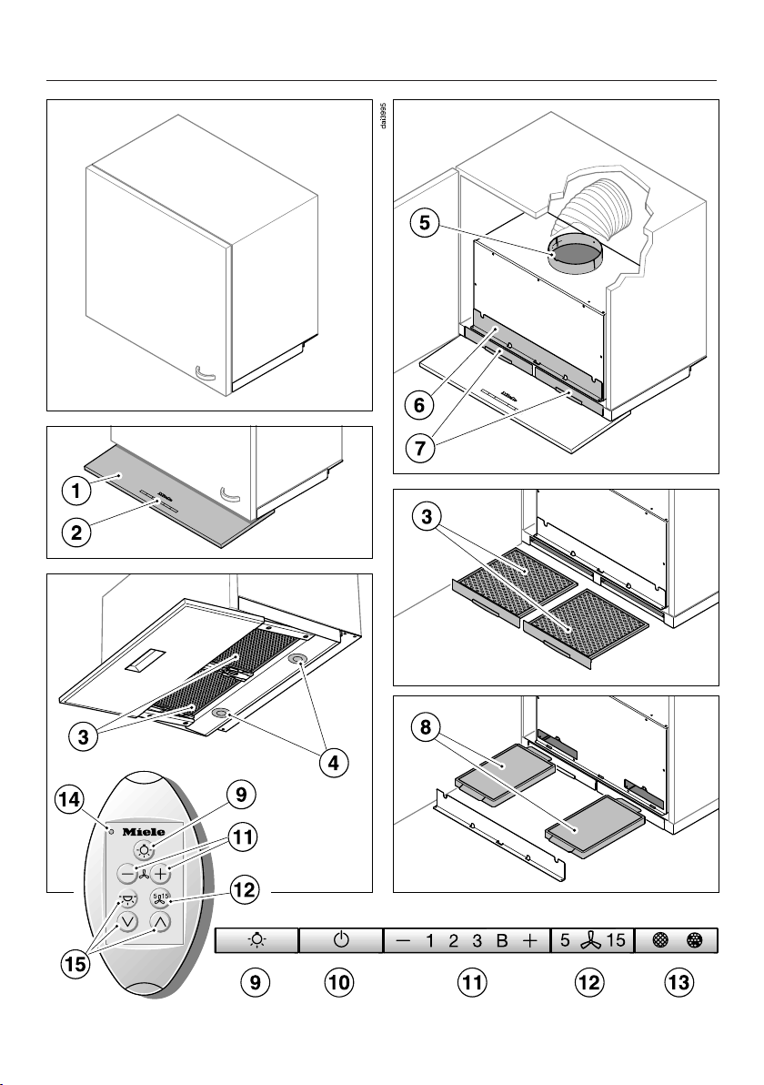
a
Retractable canopy
b
Control panel
c
Grease filters
d
Overhead lighting
e
Exhaust socket
The exhaust socket can also be fitted at the back.
f
Slots for the charcoal filters
g
Slots for the grease filters
h
Charcoal filters
Optional accessories for recirculation mode
i
Control for switching the lighting on and off and for dimming the lighting
j
Control for the retractable canopy and the blower
k
Controls for setting the blower power
The controls on the remote control are also used to extend and retract the
canopy and to switch the blower on and off.
l
Control for the delayed shutdown function
m
Control for the filter saturation indicator
This control is used for displaying operating hours used and for altering the
counter setting. See “Before using for the first time” for details on how to set
the counter for extraction mode or for recirculation mode.
n
Indicator light
o
Controls for programming
15
Page 16
Description of functions
The following functions are available on
your ventilation hood, depending on the
model:
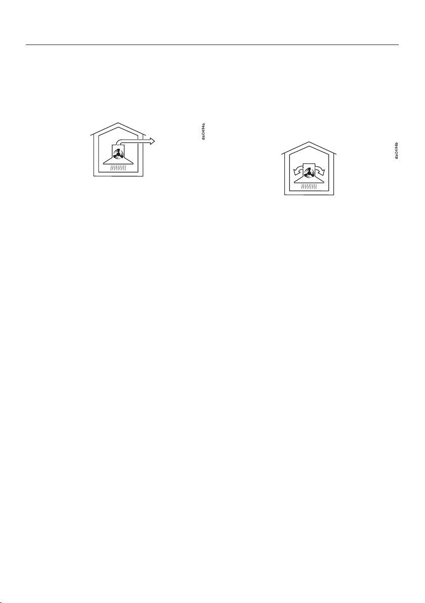
Vented mode
The air is drawn in and cleaned by the
grease filters and directed outside.
Non-return flap
A non-return flap in the ducting
prevents the exchange of inside and
outside air from occurring when the
ventilation hood is not in use.
The flap is closed when the ventilation
hood is turned off.
When the ventilation hood is turned on,
the non-return flap opens so that the
exhaust air can be transported outside
without any obstruction.
Recirculation mode
Recirculation mode hoods require a
recirculation kit and OdorFree Charcoal
Filters (available as optional
accessories), see “Technical Data” for
more information.
The air is drawn in and cleaned first by
the grease filters and then by the
charcoal filters. The clean air is then
recirculated back into the kitchen.
A non-return flap has been provided
with the hood in case your ducting does
not have one. It is inserted into the
outlet duct collar of the fan.
16
Page 17
Before using for the first time
Settings with the canopy retracted
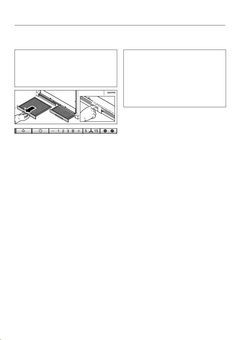
The ventilation hood must be switched
off before activating settings. The
canopy must be retracted. In order to
reach the controls when the canopy is
retracted, please note the following:
Remove the grease filters.
The controls are accessible via the slots
for the grease filters.
Selecting extraction mode or recirculation mode
The ventilation hood can be operated
with either extraction mode or
recirculation mode. The power of the
blower is adapted to suit the selected
mode of operation. The ventilation
hood is set up at the factory for
recirculation mode. It has to be reset
for extraction mode.
To reset it for extraction mode, the filter
saturation indicator for the charcoal
filter(s) has to be deactivated.
Switch off the blower and the lighting.
Press the control and the filter
saturation indicator at the same
time.
The charcoal filter symbol and one of
the blower power level indicators will
flash.
Press and hold the control until the
B indicator lights up.
Confirm the selection by pressing the
filter saturation indicator.
All the indicator lights will go out.
Extraction mode has now been set.
If the new setting is not confirmed
within 4minutes, the ventilation hood
will revert to the previous setting.
17
Page 18
Before using for the first time
Setting up Miele@home
Prerequisite:
– Home WiFi network
Your ventilation hood is equipped with
an integrated WiFi module. The
ventilation hood can be connected to
the household WiFi network.
You will then be able to operate the
ventilation hood via the Miele@mobile
app.
Before installing the ventilation hood
in its final location, ensure that the
signal of your WiFi network is strong
enough.
Please note that you cannot set up a
WiFi connection at the same time as
the wireless Con@activity 2.0 system.
Miele@mobile App
The Miele@mobile App is available to
download free of charge from the Apple
App Store® or from the Google Play
Store™.
Connecting via the app
The Miele@mobile app can be used to
connect to your network.
Install the Miele@mobile app on your
mobile device.
To log in you will need:
1. Your WiFi network password
2. Your ventilation hood password
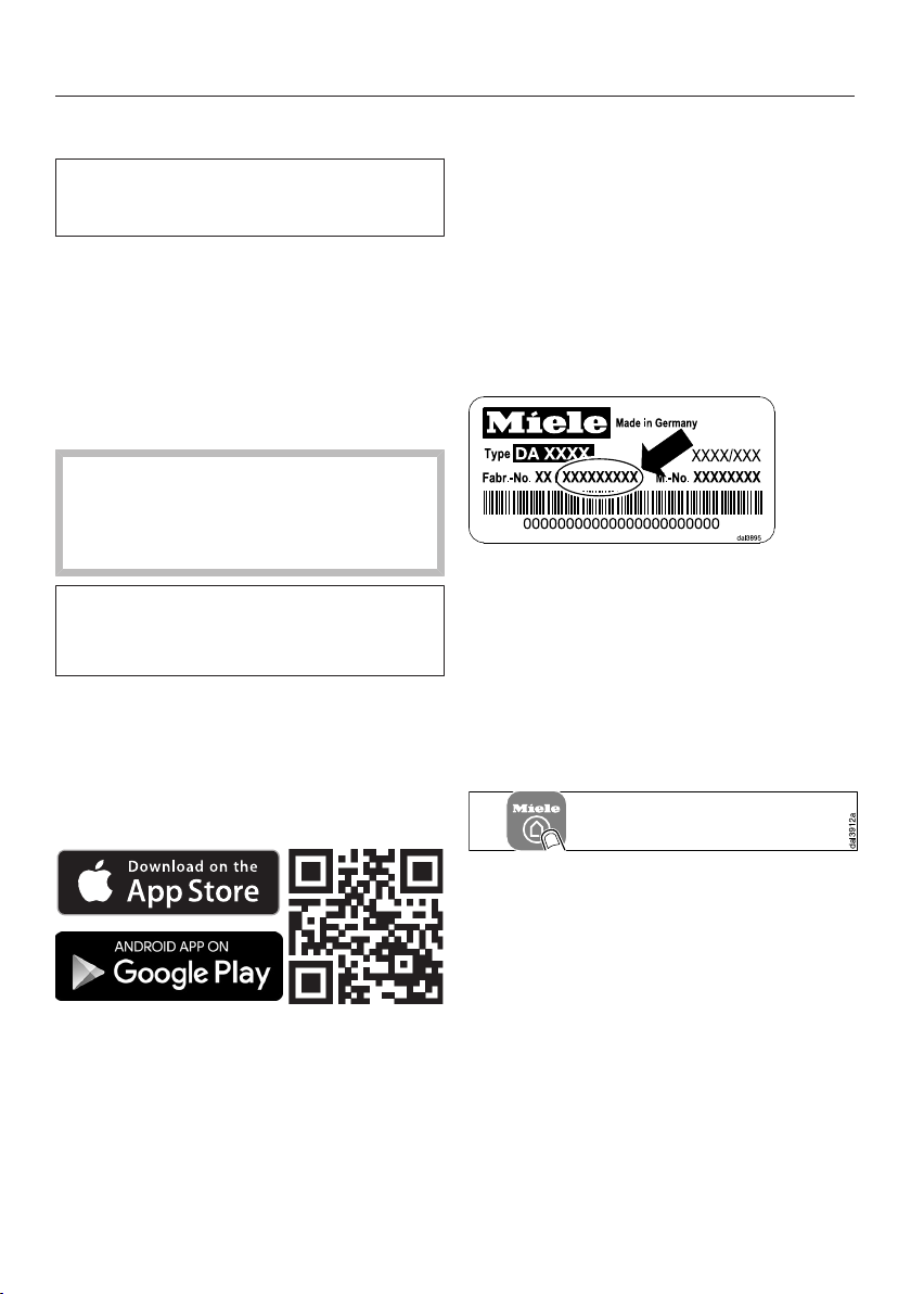
The password for your ventilation hood
consists of the last nine digits of the
serial number. This can be found on the
appliance's data plate.
The data plate is located on the housing
of the ventilation hood and is visible
when the cover for the charcoal filter
slots is removed.
18
Start signing the appliance on in the
app. Follow the signing in
instructions.
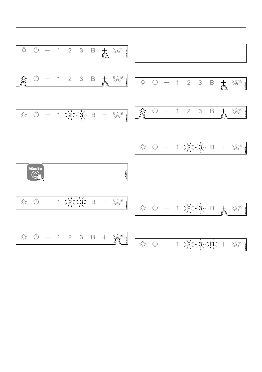
If requested to activate WiFi on the
ventilation hood, proceed as follows:
Page 19
Before using for the first time
Switch the ventilation hood off.
Press and hold the control.
Press the lighting control at the
same time.
2 will light up constantly, 3 will flash on
and off.
The ventilation hood is ready for
connection in the next two minutes.
Follow the instructions in the app.
When successfully connected, 2 and 3
will light up constantly.
Connecting via WPS
Your WiFi router must support WPS
(WiFi Protected Setup).
Switch the ventilation hood off.
Press and hold the control.
Press the lighting control at the
same time.
2 will light up constantly, 3 will flash on
and off.
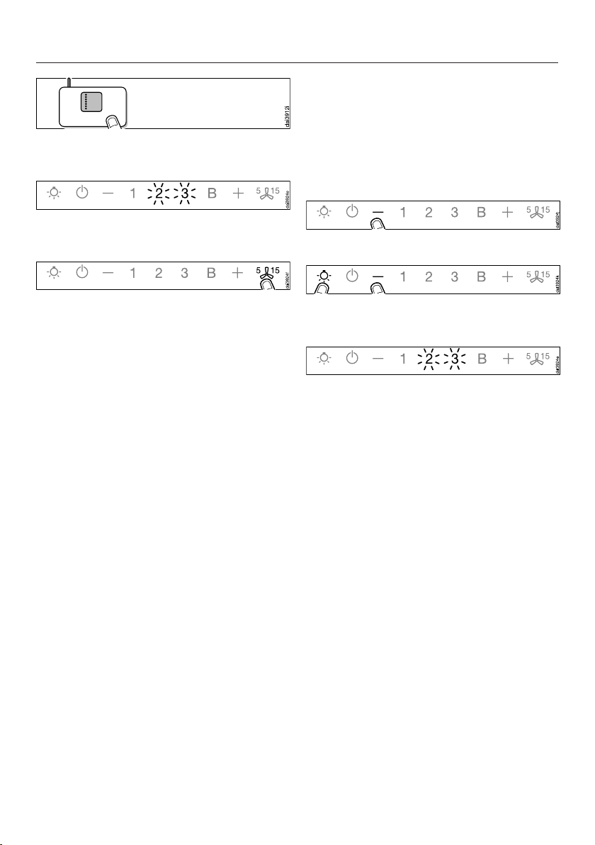
The WiFi connection must be started on
the ventilation hood at the same time as
on the WiFi router.
Press the control on the ventilation
hood after a few seconds.
Quit connection mode on the
ventilation hood by pressing the
delayed shutdown control.
The ventilation hood can now be
operated via the app.
After a short while, 2 will light up
constantly, and 3 and B will flash on
and off.
The ventilation hood is ready for
connection in the next two minutes.
19
Page 20
Before using for the first time
Start the WiFi connection on your
WiFi router.
When successfully connected, 2 and 3
will light up constantly.
Signing out of WiFi (reset to factory settings)
To set up a new WiFi connection, the
existing WiFi connection must be
disconnected.
Switch the ventilation hood off.
Press and hold the control.
Quit connection mode on the
ventilation hood by pressing the
delayed shutdown control.
The ventilation hood can now be
operated via the app.
If the connection fails, you have
probably not connected WPS to your
router quickly enough. Repeat the steps
above.
Tip: If your WiFi router does not support
WPS, please connect via the
Miele@mobile app.
Touch the lighting control at the
same time.
With an existing WiFi connection, 2 and
3 will light up constantly.
The ventilation hood is ready for
disconnection during the next two
minutes.
20
Page 21
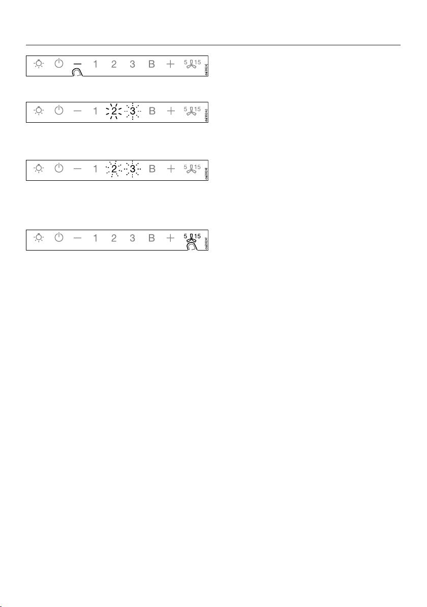
Touch the control.
2 will light up constantly, 3 will flash on
and off.
After a few seconds, 2 and 3 will flash
on and off. The connection has now
been disconnected.
Quit disconnection mode on the
ventilation hood by pressing the
delayed shutdown control.
The WiFi connection has now been
disconnected. A new connection can
now be set up.
Before using for the first time
Setting up Con@ctivity
Con@ctivity is the direct communication
system between an electric Miele
cooktop and a Miele ventilation hood. It
enables the ventilation hood to operate
automatically depending on the
operational state of a Miele cooktop
with onset controls.
– When a burner is turned on, the
overhead lighting on the hood turns
on automatically. After a brief delay,
the ventilation hood blower also
comes on.
– The ventilation hood selects the
power setting automatically during
cooking. The power level selected by
the ventilation hood depends on the
number of cooking zones being used
and their power levels.
– After switching the cooktop off, the
blower and the overhead lighting will
switch off automatically after a
specified period of time.
Detailed information about this function
can be found under “Operation”.
21
Page 22
Before using for the first time
This ventilation hood can be operated
with the Con@ctivity function via a
WiFi connection (Con@ctivity 3.0) or
via a wireless connection (Con@ctivity
2.0).
Con@ctivity via the home WiFi network (Con@ctivity 3.0)
Prerequisite:
– Home WiFi network
– WiFi enabled Miele cooktop
Connect the ventilation hood and
cooktop to your home WiFi network
(see “Setting up Miele@home”).
The Con@ctivity function will be
activated automatically.
Con@ctivity via a direct WiFi connection (Con@ctivity 3.0)
Prerequisite:
– WiFi enabled Miele cooktop
If you do not have a home network, you
can establish a direct connection
between the cooktop and the
ventilation hood.
See the cooktop operating instructions
for details on how to connect them.
Instructions on how to connect the
ventilation hood are repeated in detail
below.
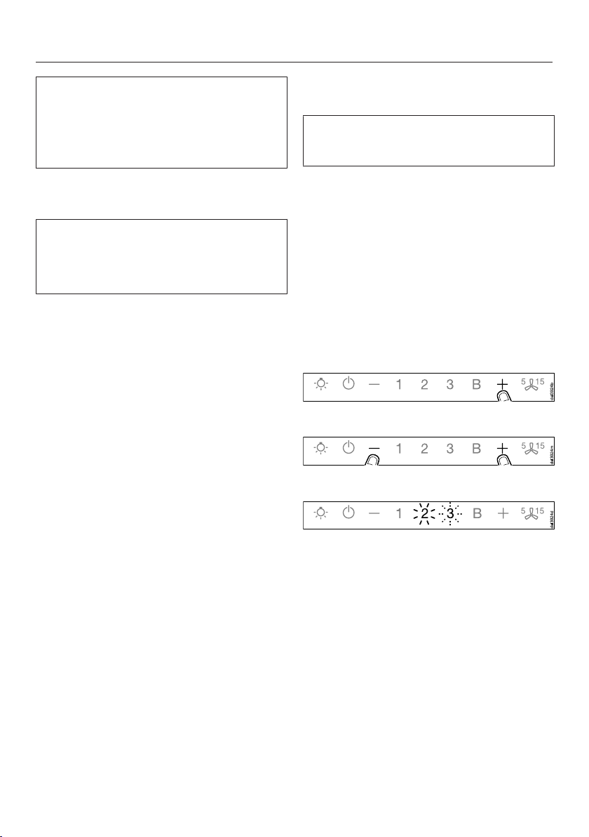
Switch the ventilation hood off.
Press and hold the control.
Press the control at the same time.
22
2 will light up constantly, 3 will flash on
and off.
The ventilation hood is ready for
connection in the next two minutes.
Page 23
Before using for the first time
Start WiFi connection on the
cooktop. For more details, see the
cooktop operating instructions.
When successfully connected, 2 and 3
will light up constantly.
Quit connection mode on the
ventilation hood by pressing the
delayed shutdown control.
Con@ctivity has now been activated.
With a direct WiFi connection, it is not
possible to connect the cooktop and
the ventilation hood to a home
network. Should this be required at a
later date, the WiFi connection
between the cooktop and the
ventilation hood must be
disconnected (see “Signing out of
WiFi”).
Con@ctivity with direct wireless connection (Con@ctivity 2.0)
Prerequisite:
– Con@ctivity 2.0 enabled Miele
cooktop
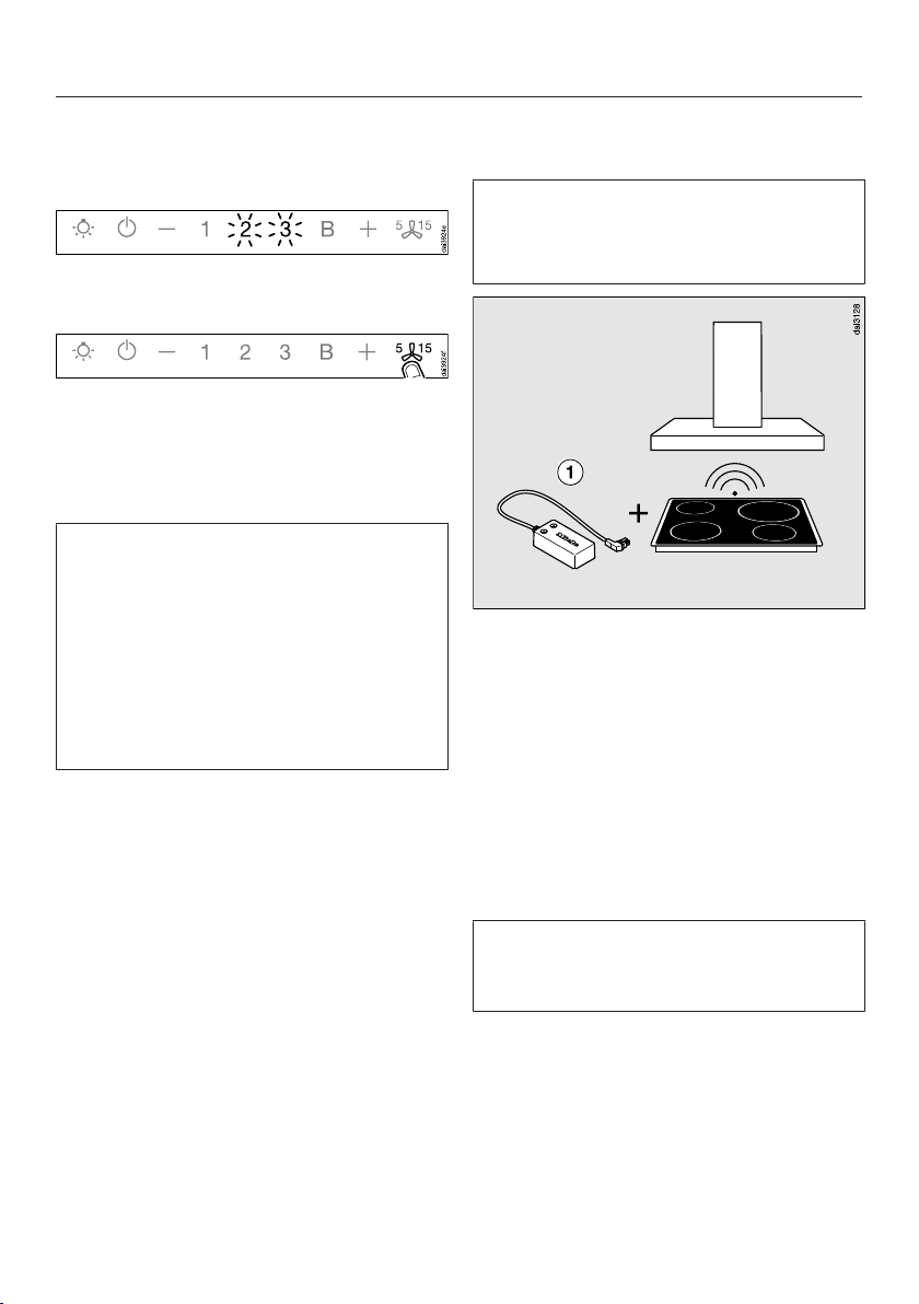
This ventilation hood is supplied with a
Con@ctivity 2.0 wireless stick .
The wireless stick can only be used
with cooktops that are fitted with a slot
for the wireless stick to operate the
Con@ctivity function.
Check the installation instructions for
the Con@ctivity 2.0 stick to ensure
that it is compatible with your
cooktop.
Please note that you cannot set up a
WiFi connection at the same time as
the wireless Con@activity 2.0 system.
23
Page 24
Before using for the first time
Installing the Con@ctivity 2.0 stick
See the relevant installation
instructions provided with the
Con@ctivity 2.0 stick.
Activating the wireless connection
The ventilation hood and the cooktop
must be installed and operational.
The wireless connection must be
activated on the ventilation hood and
the cooktop at the same time.
Activation on the ventilation hood is
described below.
Activation on the cooktop is described
in the relevant operating and installation
instructions. Please refer to the
operating instructions before starting.
Activate the ventilation hood first, then
the cooktop.
Activating the ventilation hood
The cooktop and ventilation hood
must be switched off.
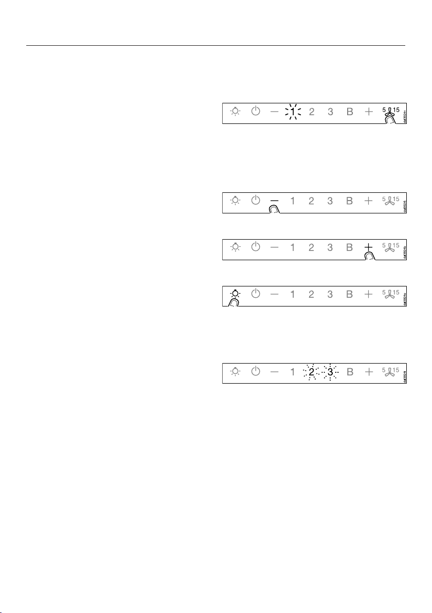
Press the delayed shutdown
control for approx. 10seconds
until 1 lights up.
Then press in order:
– the control,
– then the control,
– then the lighting control.
The ventilation hood is now in signing
on/off mode.
24
If a wireless connection has not yet
been established, 2 and 3 will flash at
the same time.
If a wireless connection has already
been established, 2 and 3 will light up
constantly (Con@ctivity 2.0 is already
activated or a remote control is signed
on).
Page 25
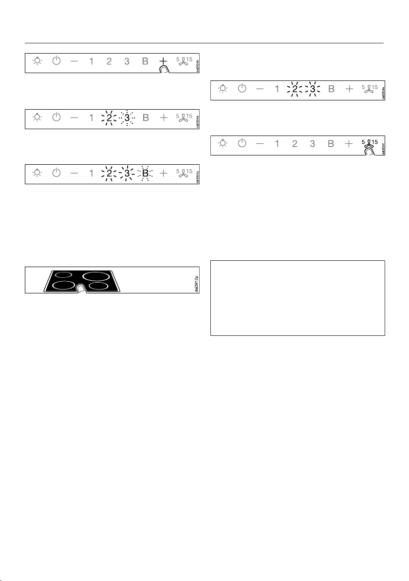
To activate Con@ctivity 2.0, press the
control.
2 will light up constantly, 3 will flash on
and off.
After a few seconds, 2 and 3 will light
up constantly, B will flash on and off.
The search for a wireless connection
will start.
Activating the cooktop
While the ventilation hood is
searching for a signal, start activating
the cooktop.
For more details, see the cooktop
operating instructions.
Before using for the first time
Finishing activation on the ventilation hood
When successfully connected, B will go
out, and 2 and 3 will light up constantly.
Confirm activation with the delayed
shutdown control. All the
indicator lights will go out.
The Con@ctivity function is now ready
for use.
If you do not confirm within 4minutes,
activation will be canceled.
You only need to carry out the
activation procedure once. If the
appliances are disconnected from the
electricity supply, for example during a
loss of power, they will still remain
activated.
When the cooktop registers that a
connection has been established, exit
activation on the cooktop.
25
Page 26
Before using for the first time
Activation failed
If a wireless connection cannot be
established despite activation of the
Con@ctivity function on the ventilation
hood and cooktop, the function must
first be deactivated and then
reactivated on both appliances.
Deactivating the wireless connection
The cooktop and ventilation hood
must be switched off.
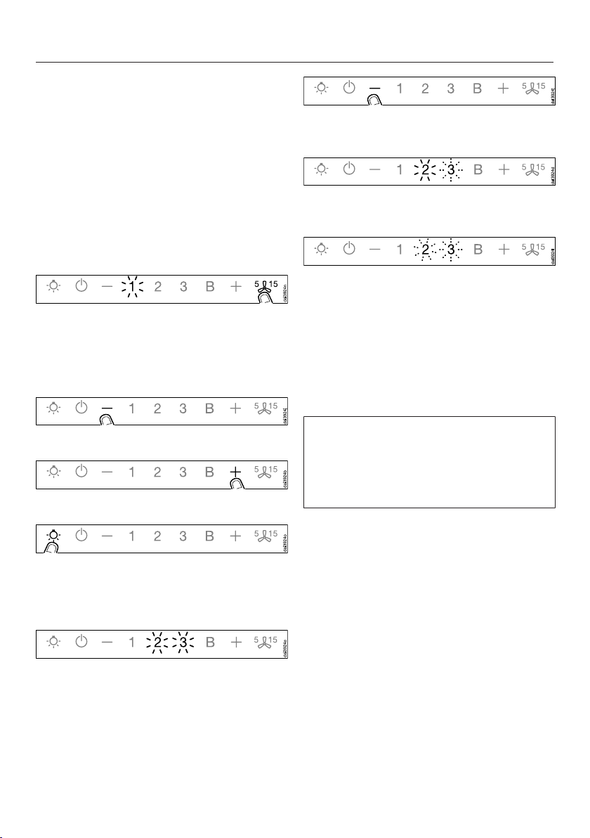
Press the delayed shutdown
control for approx. 10seconds
until 1 lights up.
Then press in order:
– the control,
– then the control,
Press the control to deactivate
Con@ctivity 2.0.
2 will light up constantly, 3 will flash on
and off.
After a few seconds, 2 and 3 will start
flashing on and off.
The wireless connection has now been
deactivated.
To deactivate the cooktop, please
refer to the corresponding operating
instructions.
Please keep in mind that disabling the
connection will also disable any
remote control function being used.
The remote control must then be
reactivated.
– then the lighting control.
The ventilation hood is now in signing
on/off mode.
If a wireless connection has already
been established, 2 and 3 will light up
constantly.
26
Page 27
Before using for the first time
Signing the remote control on/ off
If the connection has been lost between
the remote control and the ventilation
hood, the remote control and the
remote control function on the
ventilation hood must be signed on
again. To do this, the remote control
function on the ventilation hood and the
remote control must first be signed off.
Please bear in mind that disabling the
signal will also disable any
Con@ctivity 2.0 connection and this
will have to be activated again.
Switch the ventilation hood off. The
canopy must be retracted.
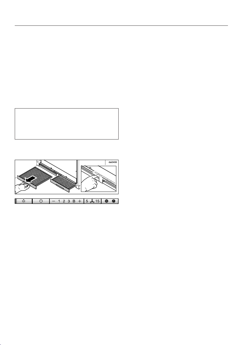
Remove the grease filters.
Signing off the remote control
Press the delayed shutdown
control on the ventilation hood
for approx. 10seconds until 1 lights
up.
Then press in order:
– the control,
– then the control,
– then the lighting control,
– then the control to sign off.
2 will light up constantly, 3 will flash on
and off.
After a few seconds, 2 and 3 will start
flashing on and off.
Confirm the signing off procedure on
the ventilation hood by pressing the
delayed shutdown control. All the
indicator lights will go out.
Press theand controls on the
remote control at the same time for
about 5seconds until the LED on the
remote control starts flashing.
The controls are accessible via the slots
for the grease filters.
Then press in turn:
– the lighting control,
– then the control to sign off.
The remote control LED flashes
steadily.
After approx. 10seconds, the remote
control LED flashes on and off twice
with a longer gap between the flashes.
The LED will go out after a short while.
The remote control is signed off.
27
Page 28

Before using for the first time
Signing on the remote control
Press the delayed shutdown
control on the ventilation hood
for approx. 10seconds until 1 lights
up.
Then press in order:
– the control,
– then the control,
– then the lighting control,
– then press the control to sign on.
2 will light up constantly, 3 will flash on
and off.
After a few seconds, 2 and 3 will light
up constantly, B will flash on and off.
Press theand controls on the
remote control at the same time for
about 5seconds until the LED on the
remote control starts flashing.
Then press in turn:
– the lighting control,
Confirm the signing on procedure by
pressing the delayed shutdown
control on the ventilation hood.
All the indicator lights will go out.
The remote control can now be used.
If you do not confirm within 4minutes,
activation will be canceled.
Canceling the signing on procedure
If it is not possible to sign on, the
procedure can be cancelled by
pressing the delayed shutdown
control on the ventilation hood
and on the remote control.
The signing on procedure must then
be repeated. To do this, the
ventilation hood and the remote
control must first be signed off.
– then press the control to sign on.
The search for a wireless connection
will start. The remote control LED
flashes steadily.
After approx. 30seconds, the remote
control LED flashes on and off four
times with short intervals between the
flashes. The LED will go out after a
short while.
Wait until B on the ventilation hood has
gone out and 2 and 3 are lit up
constantly. The wireless connection has
now been established.
28
Page 29
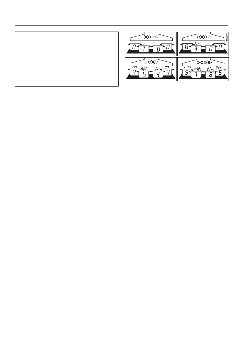
When Con@ctivity is active, the
ventilation hood always operates in
Automatic mode (see “Setting up
Con@ctivity”).
If you wish to manually operate the
ventilation hood, see “Cooking without
Con@ctivity”.
Cooking with Con@ctivity (Automatic mode)
Turn on a burner to the desired power
setting.
The overhead lighting will come on.
After a few seconds, the blower will
come on at power level 1. The canopy
extends.
The ventilation hood selects the power
setting automatically during cooking.
This level is determined by the total
output of the cooktop, i.e., the number
of burners in operation and the power
settings selected.
Operation (Automatic mode)
Examples for power levels 1 to B
Reaction time
Changing the power setting on the
cooktop does not lead to an immediate
increase or decrease in cooking vapors.
For this reason, the hood reacts with a
slight delay.
Delays can also result from the fact that
the cooktop transmits the information to
the hood in intervals.
The reaction time can vary from a few
seconds to a couple of minutes.
If you select a higher power setting
on the cooktop or switch on multiple
burners, the hood will switch to a
higher blower level.
If you select a lower power setting on
the cooktop or turn off a burner, the
hood will accordingly switch to a
lower blower level.
29
Page 30

Operation (Automatic mode)
Cooking process
If, for example, you switch on a
burner at the highest power setting to
heat cookware in preparation for
searing and then reduce the power
level after approx. 10seconds to
4minutes*, a cooking process is
recognized.
The hood turns on automatically and,
after the cooktop power level has been
reduced, switches back to blower level
3, where it remains for approx.
5minutes.
After this, the blower level is once again
determined by the Con@ctivity function.
You can also manually select a
different blower level before then.
Switching off
Turn off all burners.
Over the next few minutes, the
ventilation hood blower setting will
decrease one level at a time until the
hood eventually turns off.
This helps to neutralize any lingering
vapors and odors in the air.
– From the Booster setting, the blower
switches immediately to level3.
– From level 3, it will switch to level 2
after approx. 1minute.
– From level 2, it will switch to level 1
after 2minutes.
– After 2minutes at level 1, the blower
automatically turns off. The canopy
retracts.
– After another 30seconds, the lighting
switches off.
The cooking process is then finished.
30
Page 31

Operation (Automatic mode)
Temporarily exiting Automatic mode
To temporarily exit Automatic mode
when cooking:
Manually select a different blower
level, or
Manually turn the hood off, or
Activate the delayed shutdown
function on the ventilation hood.
The blower will switch itself off after
the selected delayed shutdown time,
the canopy will retract, and the
lighting will remain on.
The ventilation hood functions can now
be operated manually (see “Cooking
without Con@ctivity”).
Resuming Automatic mode
The ventilation hood resumes
Automatic mode:
If the ventilation hood has not been
used for a period of approx.
5minutes after the manual selection
of a blower level, or
cooktop have been switched off for at
least 30seconds after cooking,
Automatic mode will resume next
time the cooktop is switched on.
If the manually selected blower level
once again matches the automatic
setting, or
The ventilation hood blower and the
cooktop have been switched off for at
least 30seconds.
Automatic mode will resume next
time the cooktop is switched on.
You can also operate the ventilation
hood manually for a complete cooking
process.
To do so, switch the ventilation hood
blower on before the cooktop.
If the ventilation hood and the
31
Page 32
Operation (Manual mode)
Cooking without Con@ctivity (Manual mode)
The ventilation hood can be operated
manually if:
– The Con@ctivity function is not
activated.
– You have temporarily deactivated the
Con@ctivity function (see
“Temporarily exiting Automatic
mode”).
Remote control
The main functions can be selected via
the ventilation hood or by remote
control. The LED light on the remote
control unit will light up briefly when a
function is selected by remote control.
The maximum operating range of the
remote control is approx. 32' 9" (10 m).
However, this may be less depending
on the physical conditions present in
the room (e.g. furniture, walls).
Extending the canopy, switching the blower on
Switch the blower on as soon as you
start cooking. This is to ensure that
vapors are captured right from the start.
Press the control on the remote
control.
The canopy extends. The blower turns
on at level 2. The symbol and 2 will
light up in the blower level display.
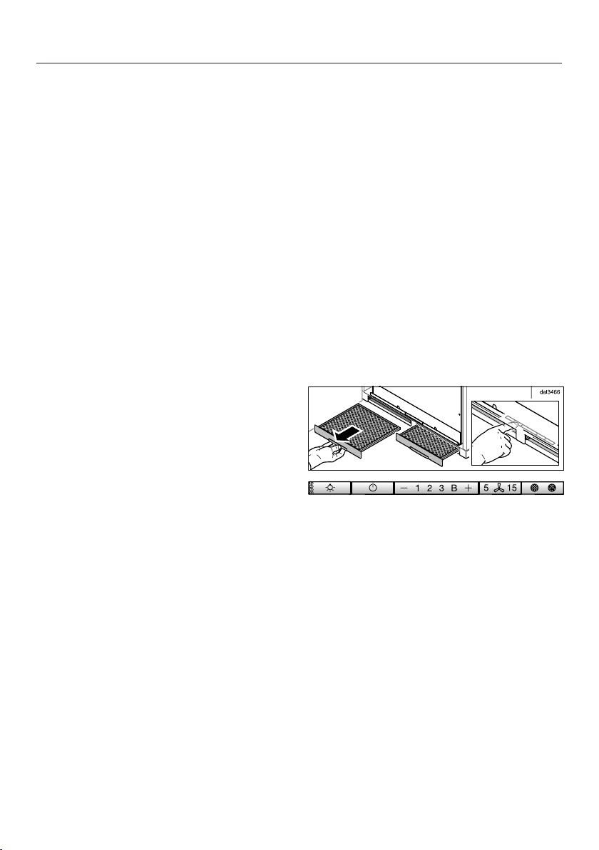
Switching on manually
The canopy can also be operated
without the remote control, e.g., if the
remote control has been misplaced or
the battery is flat.
The rear of the remote control unit is
magnetic which allows it to be attached
to various metal surfaces.
32
Remove the left-hand grease filter.
The controls can now be accessed
through the grease filter slot.
Press the On/Off control.
The canopy extends. The blower
switches on at power level 2.
Reinsert the grease filter.
Page 33

Operation (Manual mode)
Selecting the power level
Power levels 1 to 3 are available for light
to heavy cooking vapors and odors.
For strong vapors and odors that are
temporarily produced when cooking,
e.g., during searing, select the B
Booster setting.
Select the power level you want by
pressing the or control.
Reducing power down from the Booster setting
If power management is activated
(default setting), the blower
automatically switches back to level 3
after 5minutes.
Selecting the delayed shutdown time
It is advisable to run the blower for a
few minutes after cooking has finished.
This helps to neutralize any lingering
vapors and odors in the air.
It also reduces the risk of residues
accumulating in the ventilation hood
and any resultant odors.
The delayed shutdown function enables
the blower to continue running for a
pre-determined time before switching
itself off automatically.
After you have finished cooking,
press the delayed shutdown
control while the blower is still
running.
– Once: the blower will switch itself off
after 5minutes and the canopy will
go back in (5 lights up).
– Twice: the blower will switch itself off
after 15minutes and the canopy will
go back in (15 lights up).
– If you touch the delayed shutdown
control again, the blower will
remain switched on ( will go out).
33
Page 34

Operation (Manual mode)
Turning off the blower
Press the On/Off control on the
ventilation hood or the control on
the remote control repeatedly until
the blower switches off.
The blower switches off and the canopy
retracts.
If the ventilation hood is switched on
again while the canopy is retracting, the
canopy will come back out again and
then may retract again slightly.
If this happens, you must switch the
ventilation hood off and wait until the
canopy has completely retracted.
The next time you switch on the
ventilation hood, the canopy will extend
again correctly.
Dimming/switching the overhead lighting on/off
The cooktop lighting can be switched
on and off and dimmed regardless of
whether the canopy is extended or
retracted.
Power management
The ventilation hood features a power
management system for saving energy.
It is used for switching off the lighting,
reducing the fan power level and
retracting the canopy automatically
when the hood is no longer being used.
– If the booster level is selected, the
fan automatically switches to level 3
after 5 minutes.
– When the ventilation hood has been
switched on but not used for 2 hours,
the power will be reduced by one
level at a time in 30-minute stages
until the fan finally switches off. The
canopy will retract.
– If the overhead lighting is on, it
automatically turns off after 12 hours.
You can deactivate power
management.
This can, however, result in increased
energy consumption.
Press the lighting control briefly to
switch it on or off.
The lighting will switch on at maximum
brightness.
With the lighting switched on, press
and hold the lighting control. The
brightness will gradually dim until you
release the control.
To increase the brightness, press and
hold the lighting control again until
the desired level has been reached
and then release it.
34
Page 35
Operation (Manual mode)
Turning power management on/off
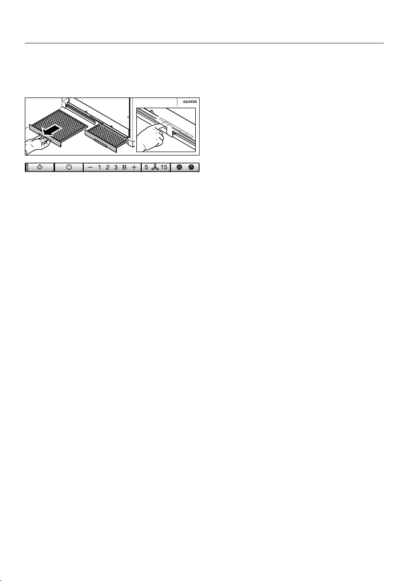
Switch the ventilation hood off. The
canopy must be retracted.
Remove the grease filters.
The controls are accessible via the slots
for the grease filters.
Press the delayed shutdown
control for approx. 10seconds
until the 1 indicator appears in the
blower level display.
Then press in turn:
– the lighting control,
– the control, and then
– the lighting control.
If the new setting is not confirmed
within 4minutes, the ventilation hood
will revert to the previous setting.
If power management is turned on, the
1 and B indicators will be continuously
lit.
If it is turned off, the 1 and B indicators
will flash.
Press the control to turn power
management off.
The 1 and B indicators will flash.
To turn it on, press the control.
The 1 and B indicators will be
continuously lit.
Confirm the setting by pressing the
delayed shutdown control.
All the indicator lights will go out.
35
Page 36
Operation (Automatic and Manual modes)
Filter saturation indicator
The ventilation hood registers the length
of time it has been operated.
The filter saturation indicators show
when the filters need to be cleaned or
changed by lighting up the grease filter
symbol or charcoal filter symbol .
Additional information on cleaning and
changing the filters and resetting the
filter saturation indicators can be found
under “Cleaning and care”.
Adjusting the filter saturation indicator for the grease filters
You can set the filter saturation
indicator to suit your cooking habits.
The factory default setting is a cleaning
interval of 30hours.
– Select a shorter interval of 20hours if
you fry food regularly.
– We also recommend a shorter
cleaning interval if you only cook
occasionally. This will prevent grease
build-up from hardening and making
cleaning more difficult.
– Select a longer cleaning interval of 40
or 50hours if you use very little fat
when cooking.
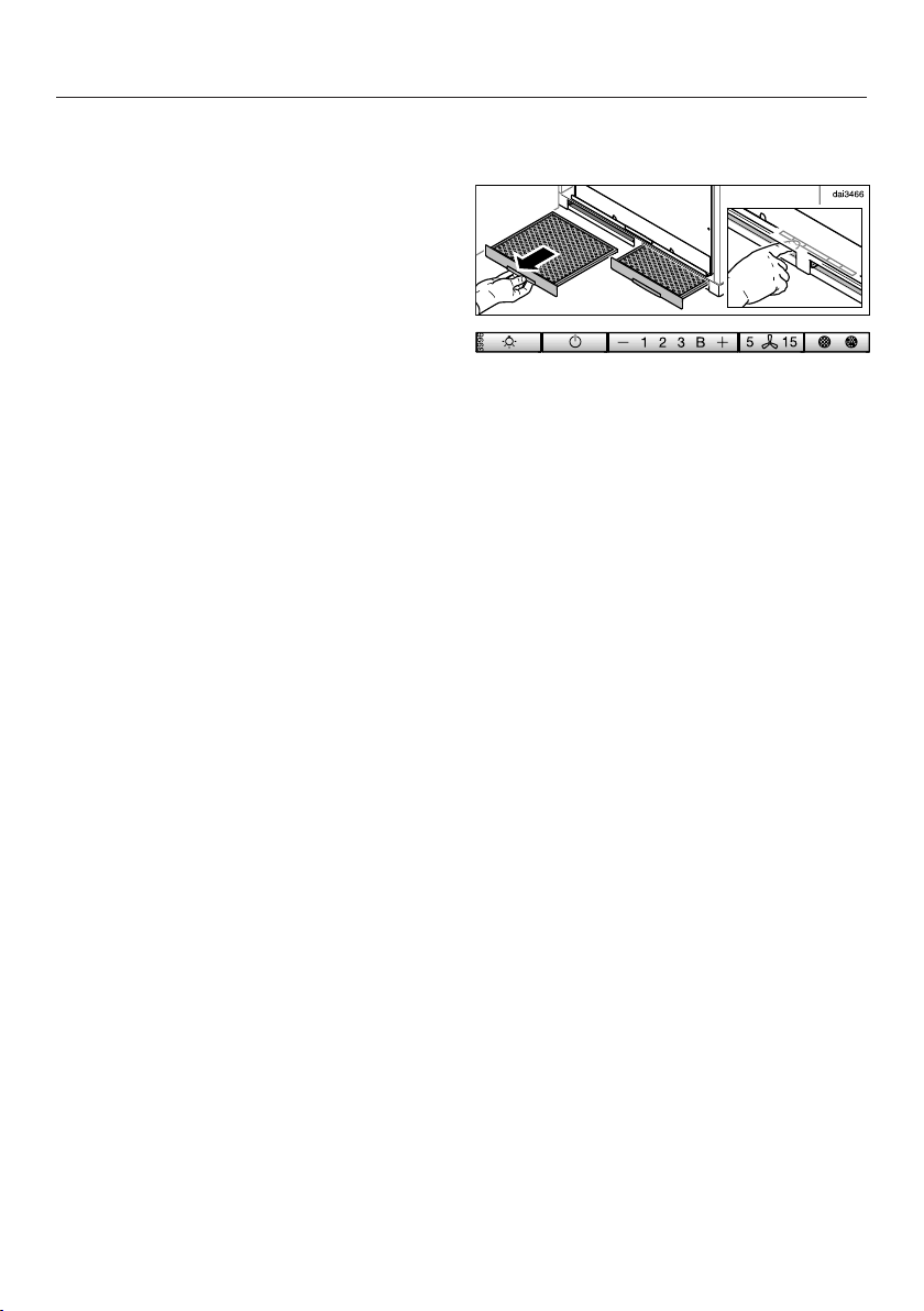
Switch the ventilation hood off. The
canopy must be retracted.
Remove the grease filters.
The controls are accessible via the slots
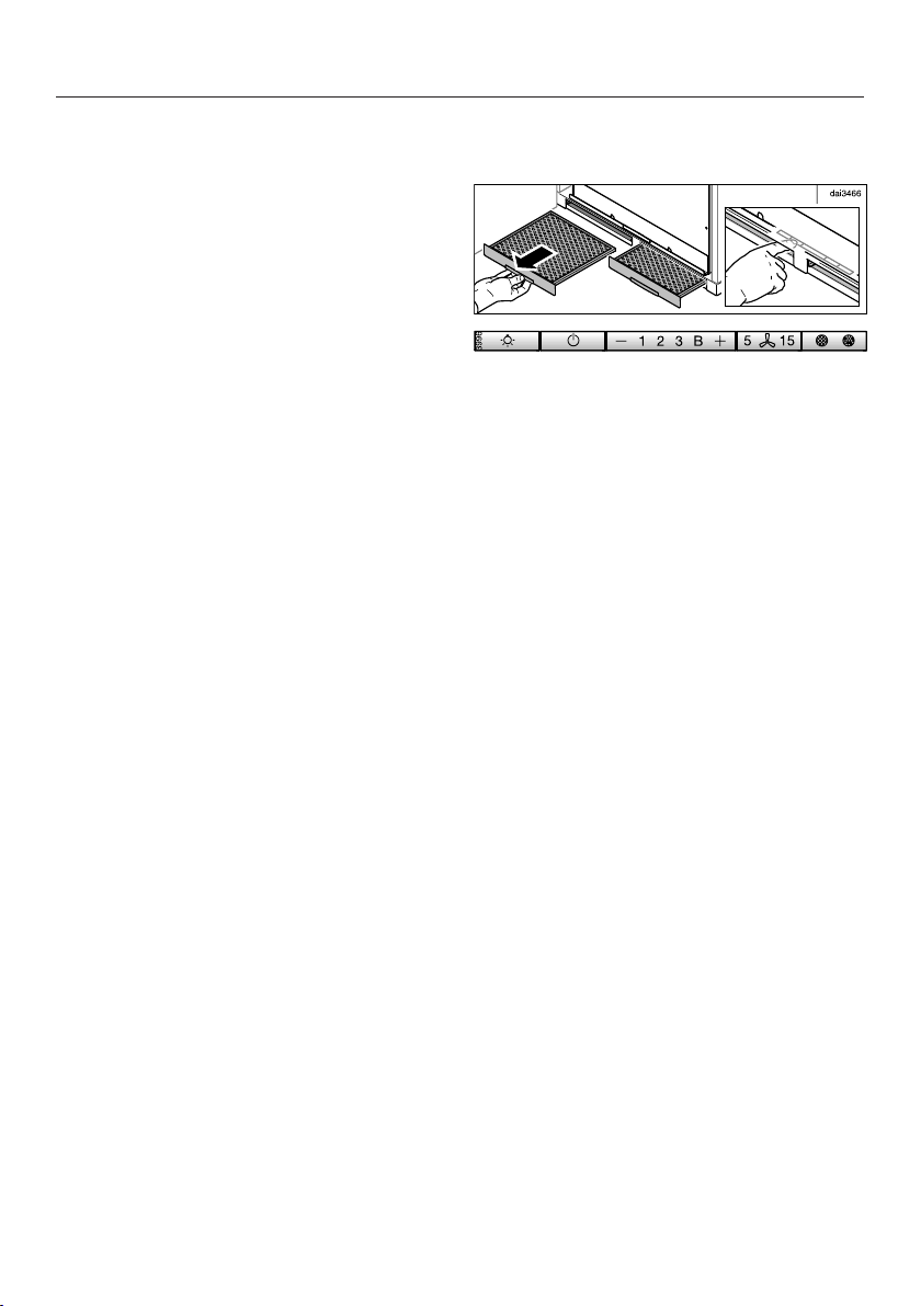
for the grease filters.
Press the delayed shutdown
control and the filter saturation
control at the same time.
The grease filter symbol and one of
the blower power level indicators will
flash.
The indicators 1 to B show the current
time setting:
1............................................... 20hours
2............................................... 30hours
3............................................... 40hours
B .............................................. 50hours
Press the control for a shorter
duration, or for a longer duration.
36
Confirm the selection by pressing the
filter saturation indicator.
All the indicator lights will go out.
If the new setting is not confirmed
within 4minutes, the ventilation hood
will revert to the previous setting.
Page 37
Operation (Automatic and Manual modes)
Adjusting or deactivating the filter saturation indicator for the charcoal filters
Charcoal filters are needed for
recirculation mode.
You can set the filter saturation
indicator to suit your cooking habits.
It has to be deactivated for extraction
mode.
It is set at the factory for 180hours of
use before it needs to be replaced.
Switch the ventilation hood off. The
canopy must be retracted.
Remove the grease filters.
The controls are accessible via the slots
for the grease filters.
Press the control and the filter
saturation indicator at the same
time.
The charcoal filter symbol and one of
the blower power level indicators will
flash.
The indicators 1 to B show the current
time setting:
1............................................. 120hours
2............................................. 180hours
3............................................. 240hours
B ......................................... Deactivated
Select the duration you want with the
or control.
Confirm your choice with the filter
saturation indicator.
All the indicator lights will go out.
If the new setting is not confirmed
within 4minutes, the ventilation hood
will revert to the previous setting.
37
Page 38

Operation (Automatic and Manual modes)
Checking the filter saturation indicator
Before the set operating time has run
out, you can check what percentage of
the time has elapsed.
Press the On/Off control to turn the
blower on.
Press and hold the filter saturation
indicator.
– Once, to check the grease filter
operating time. The grease filter
symbol lights up.
– Twice, to check the charcoal filter
operating time. The charcoal filter
symbol lights up.
One or more of the blower power level
indicators will flash simultaneously.
The number of flashing indicators
shows the elapsed operating time as a
percentage.
1 .................................................. 25%
1 and 2 ........................................ 50%
1 to 3 ........................................... 75%
1 toB ......................................... 100%
The elapsed operating time remains
stored in the memory when the
ventilation hood is turned off or in the
event of an interruption to the power
supply.
38
Page 39

Energy-saving tips
This hood operates in a very efficient
and energy-saving manner. The
following will help you to save even
more energy when using it:
– Ensure that there is sufficient
ventilation in the kitchen when
cooking. If there is insufficient air flow
during vented mode, the hood
cannot operate efficiently, causing
increased operating noise levels.
– Always cook with the lowest possible
setting. This produces fewer cooking
vapors so that you can use a lower
hood power level and therefore
benefit from reduced energy
consumption.
– Clean or change the filters at regular
intervals. Heavily soiled filters reduce
performance, increase the risk of fire
and are unhygienic.
– Use the Con@ctivity function. The
ventilation hood will switch on and off
automatically at the optimum power
level for the cooking you are doing,
which ensures low energy
consumption.
– If you are operating the ventilation
hood manually, please note the
following:
– Check the power level selected on
the ventilation hood. A low power
level is usually sufficient. Only use
the Booster setting when
necessary.
– When a large volume of cooking
vapors are being produced, switch
to a high power level in good time.
This is more efficient than
operating the hood for longer to try
to capture cooking vapors that
have already been distributed
throughout the kitchen.
– Make sure that you switch off the
hood after use.
If cooking vapors and odors still
need to be removed from the
kitchen air after cooking, use the
delayed shutdown function. The
blower will switch off automatically
after the selected delayed
shutdown time.
39
Page 40
Cleaning and care
WARNING: TO REDUCE THE
RISK OF FIRE, ELECTRIC SHOCK,
OR INJURY TO PERSONS,
OBSERVE THE FOLLOWING:
Before cleaning or servicing the
hood, disconnect it from the power
supply, see “IMPORTANT SAFETY
INSTRUCTIONS”.
Stainless steel housing
General information
The surfaces and control buttons
are susceptible to scratching and
chipping.
Observe the following cleaning
instructions.
Clean all surfaces and control buttons
using warm water and liquid dish
soap. Apply with a sponge cloth.
Make sure that no water gets
into the interior of the hood.
Only use a damp cloth to clean the
hood, especially in the control panel
area.
Special instructions for stainless steel surfaces
(does not apply to control buttons)
Stainless steel surfaces can also be
cleaned using a non-abrasive
stainless steel cleaner, available from
Miele.
To prevent the surfaces from quickly
becoming dirty again, we recommend
treating them with a stainless steel
care conditioner.
Apply sparingly over the entire area
using a soft cloth.
Important for the controls
Do not leave dirt and debris on the
buttons for any length of time.
Otherwise they may become
discolored or damaged.
Remove any dirt or debris
immediately.
Observe the general cleaning
instructions contained in this chapter.
Do not use a stainless steel cleaner
to clean the control buttons.
After cleaning, dry the surfaces with a
soft cloth.
Avoid the following:
– Cleaners containing soda, acid or
chloride, or cleaners containing
solvents
– Abrasive sponges, e.g. pot scourers
or sponges which have been
previously used with abrasive
cleaning agents.
40
Page 41
Cleaning and care
Grease filters
Risk of fire!
Oversaturated grease filters are a fire
hazard.
Clean the grease filters at regular
intervals.
The reusable metal grease filters in the
appliance remove the solid particles
contained in kitchen vapors (grease,
dust, etc.), thereby preventing the
ventilation hood from becoming dirty.
The grease filters must be cleaned at
regular intervals.
Heavily soiled grease filters hinder air
extraction and will lead to increased
levels of soiling in the ventilation hood
and in the kitchen.
Cleaning intervals
Accumulated grease solidifies over a
longer period of time and makes
cleaning more difficult. The grease
filters should therefore be cleaned every
3 to 4 weeks.
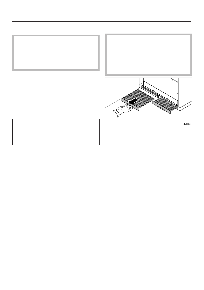
Removing the grease filters
When handling the grease filter,
be careful not to drop it.
This can result in damage to the filter
and the cooktop below.
Make sure you hold the filter securely
at all times when handling it.
Remove the grease filters from the
slots on the front of the housing.
Cleaning the grease filters by hand
Clean the filters with a soft nylon
brush in a mild solution of hot water
and dish soap. Do not use undiluted
dish soap.
The filter saturation indicator reminds
you to regularly clean the grease filters
by illuminating the grease filter symbol
.
You can adjust the interval for the
filter saturation indicator to match
your cooking habits (see
“Operation”).
41
Page 42

Cleaning and care
Unsuitable cleaning agents
Unsuitable cleaners can cause damage
to the filter surfaces if used regularly.
Do not use any of the following:
– Lime removers
– Abrasive powders or abrasive liquids
– Aggressive all-purpose cleaners and
degreaser sprays
– Oven sprays
Cleaning the grease filters in a dishwasher
Place the grease filters upright or
slightly inclined in the lower basket.
Ensure the spray arm is not
obstructed.
Use a commonly available household
dishwashing detergent.
In a Miele dishwasher use the
“Normal” program.
Depending on the detergent used,
cleaning the filters in a dishwasher
may cause the inside filter surfaces to
become discolored. However, this will
not affect the functioning of the grease
filters in any way.
After cleaning
After cleaning, leave the filters on an
absorbent surface to dry.
When removing the filters for
cleaning, also clean off any
accessible oil or fat buildup from the
housing. Doing so will prevent a fire
hazard.
Refit the grease filters.
Resetting the filter saturation indicator for the grease filters
Once cleaning is complete, the filter
saturation indicator must be reset.
While the blower is turned on, press
the filter saturation indicator for
approx. 3seconds until 1 is the only
indicator flashing.
The grease filter symbol goes out.
When cleaning the grease filters before
the full operating time has elapsed:
Press the filter saturation
indicator for approx. 6seconds
until 1 is the only indicator flashing.
42
Page 43
Cleaning and care
OdorFree Charcoal Filter
With recirculation mode, two charcoal
filters must be fitted in addition to the
grease filters. These are designed to
absorb cooking odors.
Charcoal filters are available to order via
the Miele Web Store (see end of this
booklet for contact details), or from
your Miele dealer.
The charcoal filters are listed under
“Technical data” at the back of this
booklet.
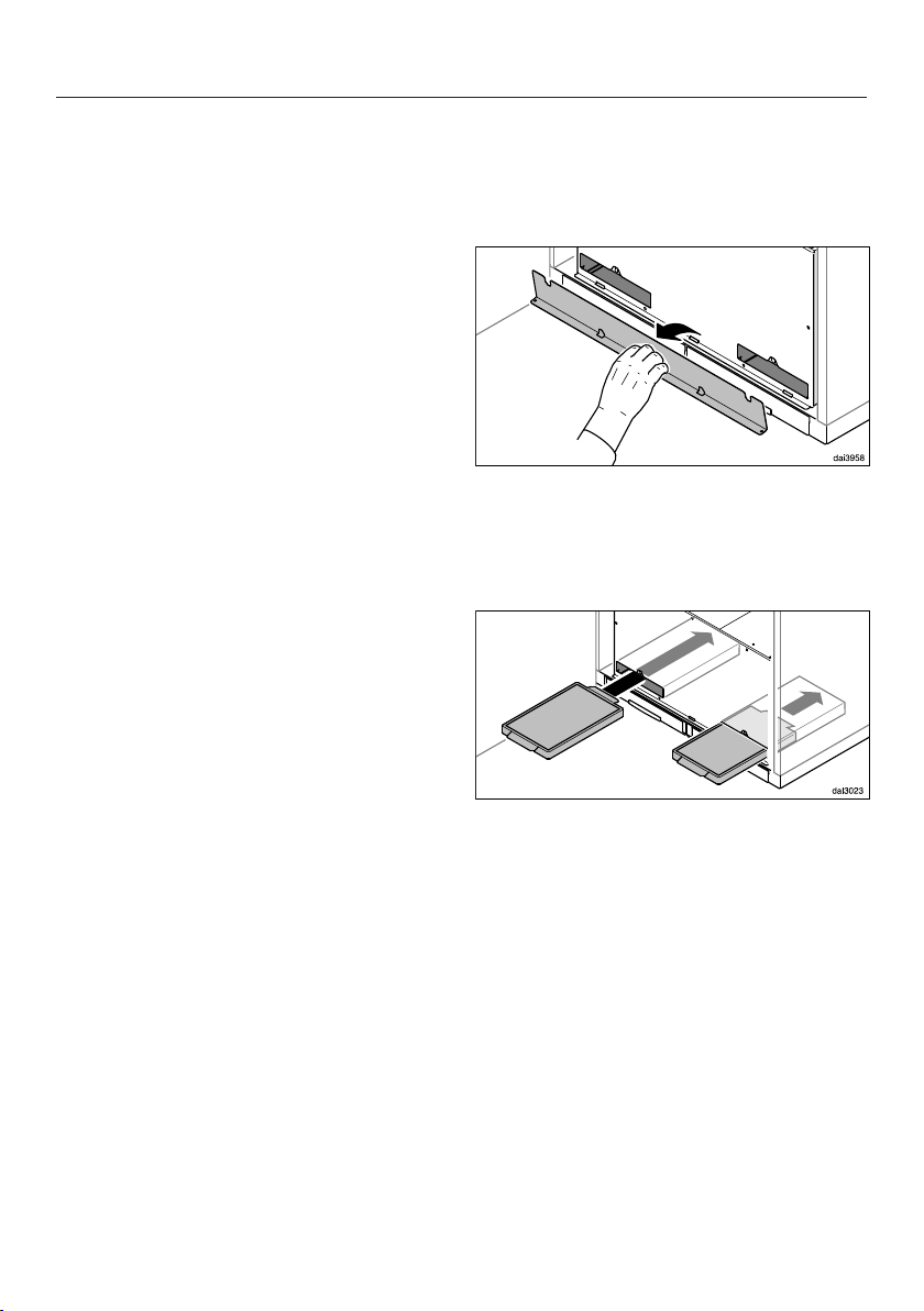
How to install/replace a charcoal filter
The slots for the charcoal filters are
located above the grease filters.
Remove the cover. It is held in place
by magnets.
Take the charcoal filters out of their
packaging.
Insert the charcoal filters in the slots.
Replace the cover.
43
Page 44

Cleaning and care
When to change the OdorFree Charcoal Filter
Replace the charcoal filters when
they no longer absorb kitchen odors
effectively.
They should, however, be replaced at
least every 6months.
The filter saturation indicator reminds
you to regularly clean the charcoal
filters by illuminating the charcoal filter
symbol.
Resetting the filter saturation indicator for the charcoal filters
After changing the charcoal filters, the
filter saturation indicator must be reset.
To do this, press the filter saturation
indicator twice with the blower
turned on and hold it for approx.
3seconds until 1 is the only indicator
flashing.
The charcoal filter symbol will go
out.
If you want to replace the charcoal
filters before the full operating time
elapses:
Press the filter saturation
indicator twice and hold it for
approx. 6seconds until 1 is the only
indicator flashing.
Disposing of charcoal filters
Used charcoal filters can be disposed
of with normal household waste.
44
Page 45
Remote control
Cleaning the remote control
Only clean the surface with a damp
cloth. Do not use too much water to
avoid moisture penetrating the
casing.
Changing the battery
Use only the type of battery listed.
Do not use rechargeable batteries.
Cleaning and care
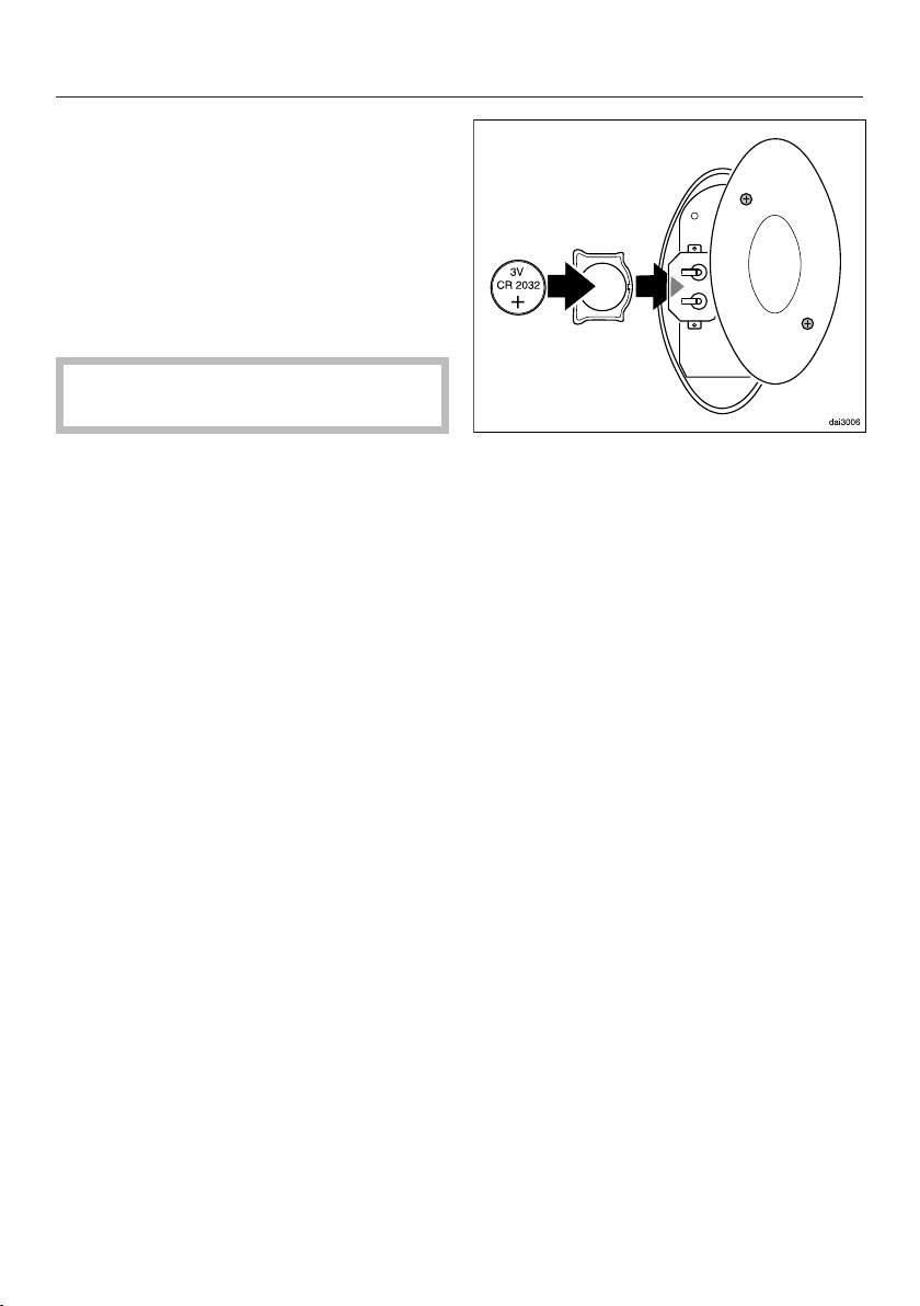
The remote control requires one 3V CR
2032 battery.
The battery must be changed if
ventilation hood functions can no longer
be selected using the remote control. If
the indicator light on the remote control
no longer lights up or lights up only
weakly when a control is pressed, the
battery is exhausted.
Ventilation hood functions can still be
selected using the controls on the
ventilation hood.
Use a screwdriver to loosen the two
screws on the back and remove the
cover.
Remove the old battery and replace
with a new one. Make sure the
polarity is correct.
Refit the cover and secure with the
two screws.
45
Page 46
Installation
Installation parts
46
Page 47
a
Montage
Installation
Montaje
Montaggio
Montering
Montagem
Asennus
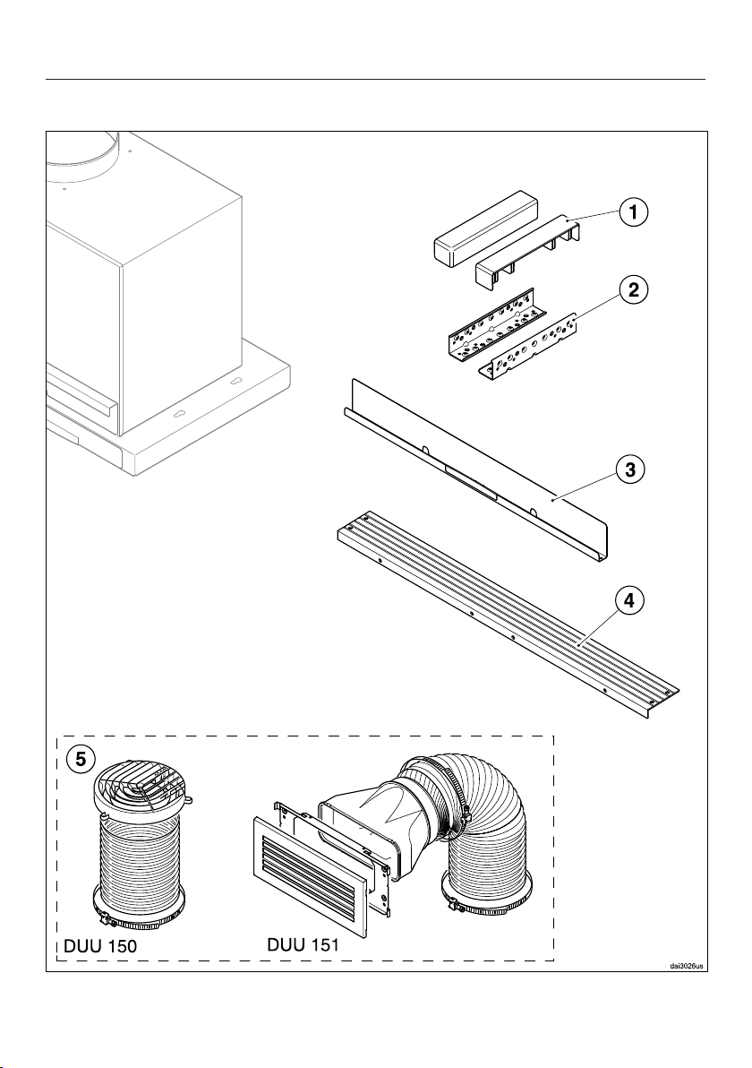
2 covers for the brackets.
b
2 brackets to support the appliance
in the wall unit.
c
1 cover for the charcoal filter slots.
d
1 spacer strip to conceal the gap
between the rear of the appliance
and the wall.
e
Conversion kit for recirculation
mode (the conversion kit is not
supplied. It must be ordered
separately as an optional accessory
- see “Technical data”). The kit
contains an exhaust grille and
flexible aluminum hose with hose
clips.
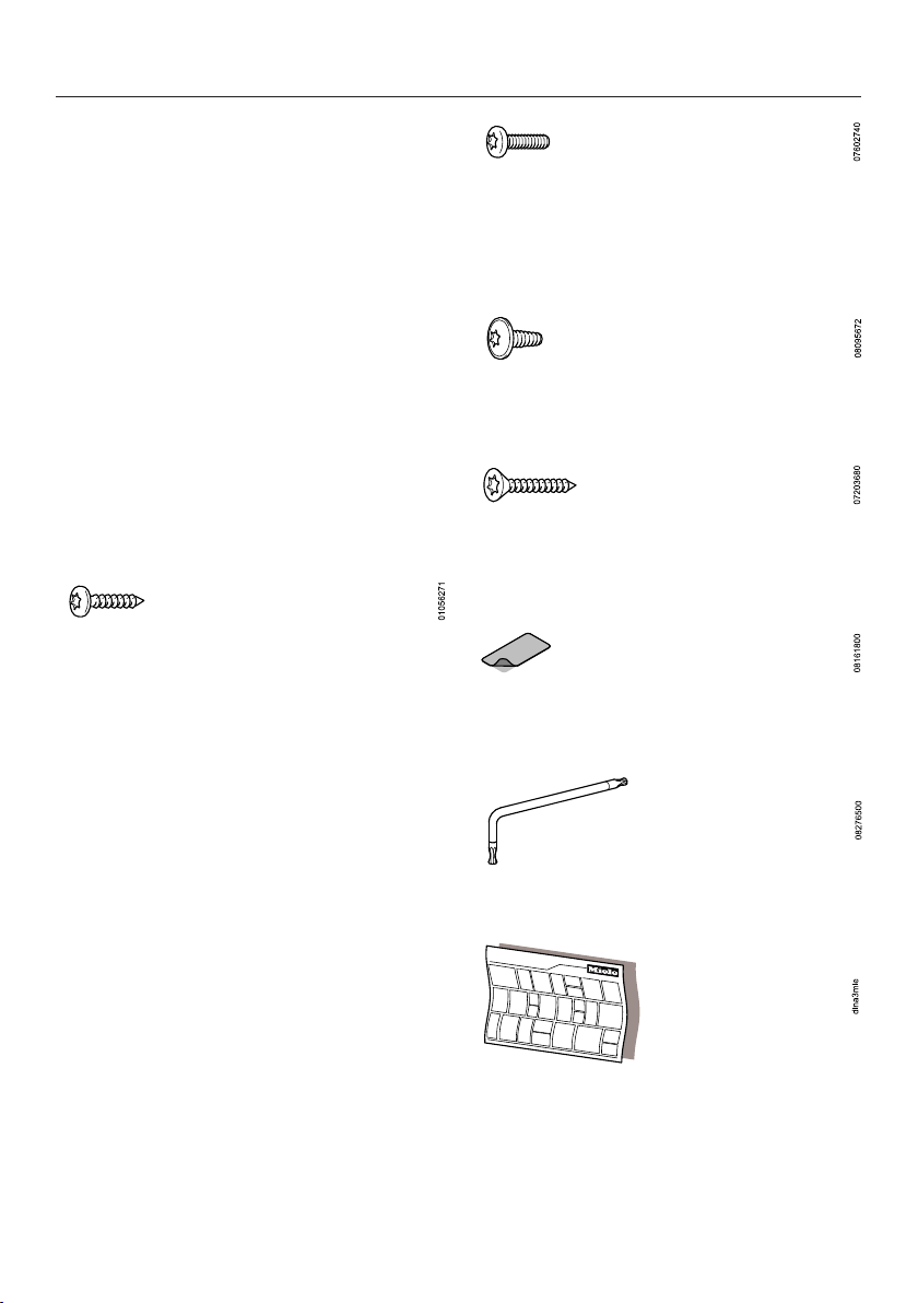
12 screws 4 x 15 mm ⁹/₁₆") for
securing the ventilation hood to the
wall unit.
Installation
4 screws M4 x 16 mm (⁵/₈") for
securing the ventilation hood to the
brackets and for securing the spacer
strip.
4 screws M4 x 8 mm (⁵/₁₆") for
securing the spacer strip.
4 screws 4 x 25 mm (1“) for securing
a 900mm (35 ⁷/₁₆”) wide ventilation
hood.
4 adhesive covers to conceal the
fixing holes which are not required.
1 x T 20 angled key
Installation instructions
47
Page 48
Installation
Appliance dimensions
48
Page 49
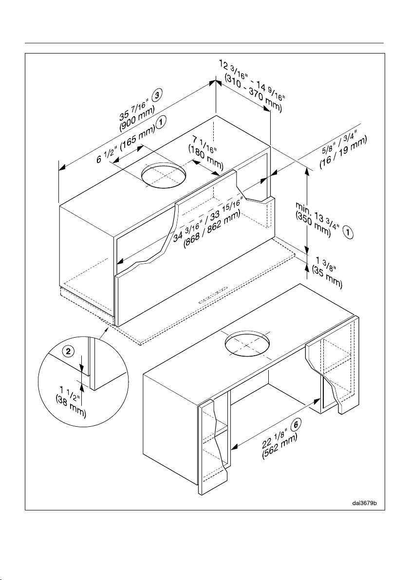
Installation
49
Page 50

Installation
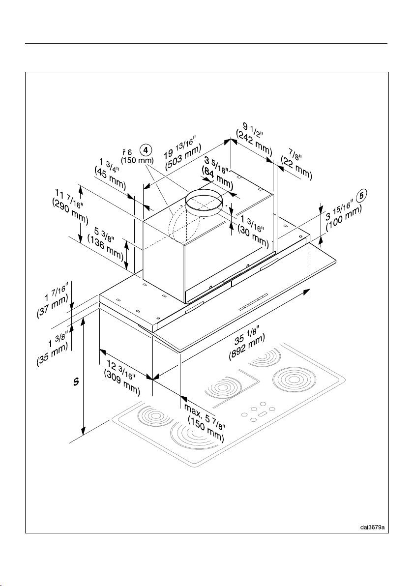
a
Vented, recirculation with conversion
kit DUU150.
(When using the recirculation
conversion kit DUU151, please note
the dimensions in the corresponding
installation instructions)
b
The wall cabinet housing needs to
be 1 ¹/₂" (38mm) shorter than the
wall cabinet door.
c
Installation is also possible in a
23 ⁵/₈" (600mm) wide cabinet.
The following should be noted:
– The adjacent cabinetry must also
be shortened by 1 ¹/₂" (38mm).
– The doors of the built-in and
adjacent cabinetry must open at
the top so that the grease filters
are accessible.
d
The ducting can also be connected
at the back.
e
The upper cabinet can be installed
with a partition after installation.
Slots for the grease filters and
charcoal filters (for recirculation
mode) must remain accessible.
f
Alternatively, the upper cabinet can
be installed with side sections.
50
Page 51
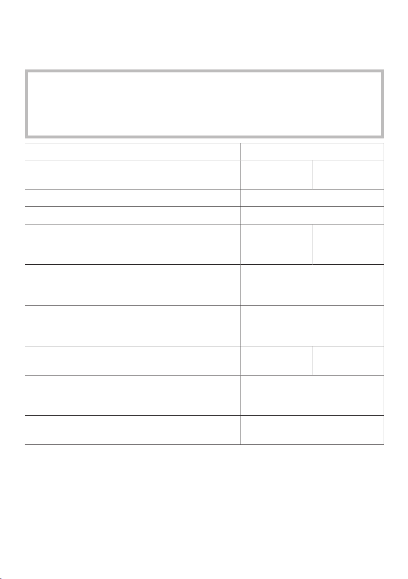
Installation
Distance between cooktop and ventilation hood (S)
Provided a larger distance is not given by the manufacturer of the cooktop,
follow the minimum safety distances between a cooktop and the bottom of the
hood.
Please also observe the information contained in the “IMPORTANT SAFETY
INSTRUCTIONS” section.
Minimum distance S
Cooking appliance Miele
appliance
Electric Cooktops 24" (610 mm)
Electric Barbeques and Fryers 26" (660 mm)
Multiburner Gas Cooktops
≤ 43,000 BTU/hr (12.6kW),
no burner > 15,000 BTU/hr (4.5 kW).
Multiburner Gas Cooktops
≤ 73,800 BTU/hr (21.6kW),
no burner > 16,500 BTU/hr (4.8 kW)
Multiburner Gas Cooktops
> 73,800 BTU/hr (21.6kW),
or one of the burners > 16,500 BTU/hr (4.8 kW)
Single Burner Gas Cooktops
≤ 20,500 BTU/hr (6 kW)
Single Burner Gas Cooktops
> 20,500 BTU/hr (6 kW)
≤ 27,600 BTU/hr (8.1 kW)
Single Burner Gas Cooktops
> 27,600 BTU/hr (8.1 kW)
26" (660 mm) 30" (760 mm)
30" (760 mm)
Not possible
26" (660 mm) 30" (760 mm)
30" (760 mm)
Not possible
Non-Miele
appliance
51
Page 52

Installation
Installation recommendations
– To achieve optimum vapor extraction,
the hood must be centered over the
cooktop, not to the side.
– The cooktop should be no wider than
the hood. Preferably, it should be
narrower for better extraction.
– The mounting area must be easily
accessible. The ventilation hood
should be easy to reach and
disassemble in case a service call is
necessary. This should be taken into
consideration when planning the
position of cabinetry, shelves,
ceilings or decorative elements in the
vicinity of the ventilation hood.
Before installation
Before installing the appliance,
read all of the information contained
in this chapter and also in the
“IMPORTANT SAFETY
INSTRUCTIONS” section.
52
Page 53
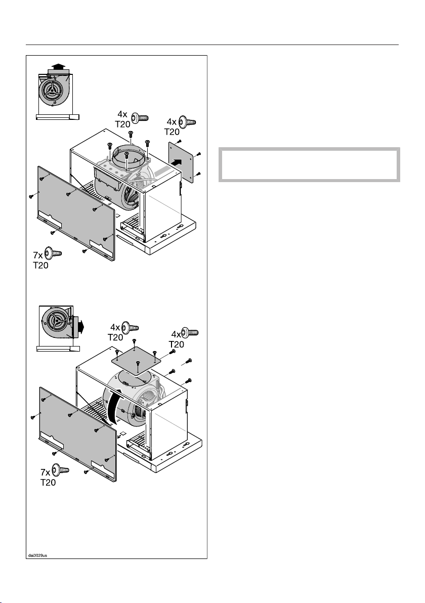
Installation
Repositioning the ducting
The blower can be rotated to allow the
ducting to be fitted at the back of the
hood. This may be necessary if the
hood is being fitted in a reduced height
wall unit, for example. Repositioning is
carried out before installing the hood.
The ventilation hood must be
disconnected from the power supply.
Undo the fixing screws on the front
panel of the ventilation hood housing
and remove the panel.
Undo the screws from the cover on
the back of the ventilation hood
housing and remove the cover.
Unscrew the fixing screws on the
motor unit.
Turn the fan towards the rear and
position the exhaust socket in the
cut-out in the back panel of the
ventilation hood housing. Ensure
when turning the fan that the power
cord does not become detached.
Secure the fan in its new position.
Now secure the cover taken from the
back panel to the top of the housing.
Refit the front panel and secure it
using the screws.
53
Page 54

Installation
Installation Instructions
Please refer to the accompanying
installation sheet for instructions on
how to install the appliance.
Leave these instructions with the
appliance for the consumer/user.
Information is subject to change. Please
refer to our website to obtain the most
current product specification, technical
& warranty information.
54
Page 55
Electrical connection
WARNING: TO REDUCE THE RISK
OF FIRE, ELECTRIC SHOCK, OR
INJURY TO PERSONS, OBSERVE
THE FOLLOWING:
All electrical work should be
performed by a qualified electrician
in strict accordance with national
regulations (for USA: ANSI-NFPA 70)
and local safety regulations.
Installation, repairs and other work
by unqualified persons could be
dangerous.
Ensure that power to the appliance is
OFF while installation or repair work
is performed.
Verify that the voltage, load and
circuit rating information found on
the data plate (located behind the
baffle filters), match the household
electrical supply before installing the
hood.
Use only with ventilation hood cordconnection kits that have been
investigated and found acceptable
for use with this model hood.
If there is any question concerning
the electrical connection of this
appliance to your power supply,
please consult a licensed electrician
or call Miele’s Technical Service
Department.
Grounding Instructions
WARNING - Improper grounding can
result in a risk of electric shock.
This appliance must be grounded. In
the event of an electrical short circuit,
grounding reduces the risk of electric
shock by providing a path of least
resistance. This appliance is equipped
with a cord having a grounding wire
with a grounding plug.
If there is any doubt, have the electrical
system of the house checked by a
qualified electrician.
Do not use an extension cord. If the
power supply cord is too short, have a
qualified electrician install an outlet near
the appliance.
The plug must be plugged into an
outlet that is properly installed and
grounded.
WARNING - Grounding instructions
(Canada)
The grounding-type attachment plug
shall be connected to a groundingtype receptacle installed in
accordance with CSA C22.1-12,
Canadian Electrical Code, Part I.
WARNING: THIS APPLIANCE MUST
BE GROUNDED
55
Page 56
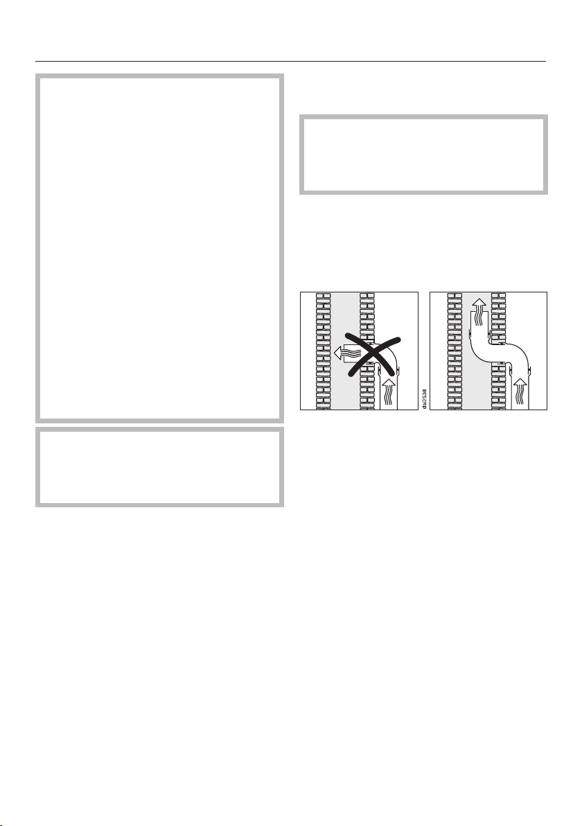
Air venting
WARNING: Danger of toxic fumes.
Gas cooking appliances release
carbon monoxide that can be
harmful or fatal if inhaled.
To reduce the risk of fire and to
properly exhaust air, the exhaust
gases extracted by the hood should
be vented outside of the building
only.
Do not vent exhaust air into spaces
within walls or ceilings or in attics,
crawl spaces or garages.
To reduce the risk of fire, only use
metal ductwork.
Please read and follow the
“IMPORTANT SAFETY
INSTRUCTIONS” to reduce the risk
of personal injury. Follow all local
building codes when installing the
hood.
Only use smooth pipes or flexible
duct hoses made from noncombustible materials for exhaust
ductwork.
To achieve the greatest possible air
extraction with the lowest noise levels,
please note the following:
– The diameter of the exhaust duct
should not be less than 6" (150mm).
– If flat exhaust ducts are used, the
cross section should not be smaller
than that of the exhaust connector.
– The exhaust duct should be as short
and straight as possible.
– Make sure that all connections are
secure and airtight.
Remember that any constriction of
the airflow will reduce extraction
performance and increase operating
noise.
If the exhaust duct is to be routed
through an outside wall, we
recommend installing a telescopic
wall vent or a rooftop vent (available
as an optional accessory).
If the exhaust air is conveyed into an
exhaust air chimney, the inlet
connector must face the flow
direction.
When installing the exhaust duct
horizontally, a minimum slope of ¹/₈
inch per foot must be maintained to
prevent condensate from flowing into
the ventilation hood.
If the exhaust duct is to be routed
through cool rooms, ceilings, etc., the
temperatures in these different areas
may differ greatly. Therefore water
condensation must be considered
and the exhaust duct will need to be
insulated.
– If elbows are needed, make sure they
have a large radius.
– The exhaust duct itself must not be
kinked or compressed.
56
Page 57
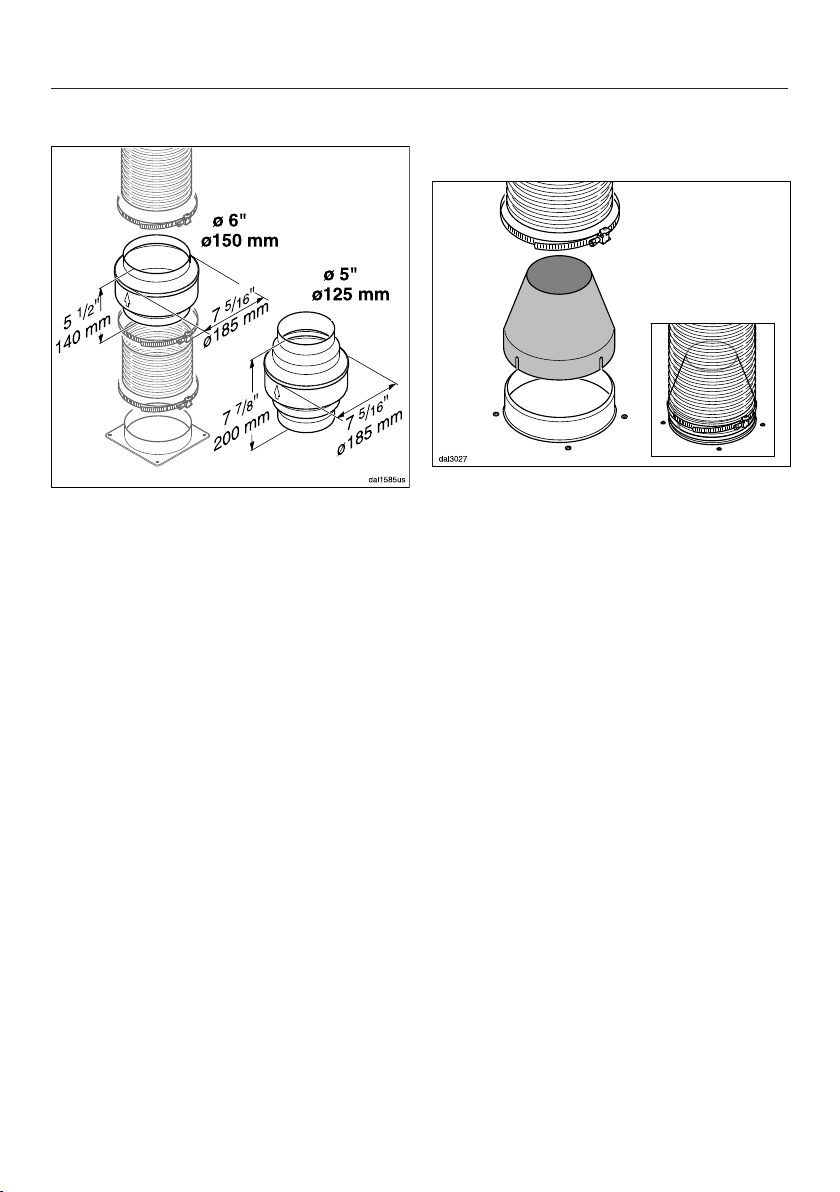
Air venting
Condensate trap
In addition to insulating the exhaust
duct, we recommend installing a
condensate trap to collect and
evaporate any condensate which might
accumulate.
Condensate traps are available for
exhaust ducts with a diameter of
5" (125 mm) or 6" (150 mm).
When installing a condensate trap,
make sure that it is positioned
vertically and, if possible, directly
above the hood outlet duct collar.
The arrow on the housing indicates
the direction of airflow.
Reducing Collar
(optional accessory)
If you would like to reduce the
environmental impact of your ventilation
system by limiting the CFM output the
Reducing Collar can be installed. It
reduces the air flow to less than
400CFM. Check local building codes
for max. CFM requirements.
Push the Reducing Collar on the
exhaust port of the blower.
Push the exhaust hose over it.
Secure both with a hose clamp.
57
Page 58

Service and warranty
For faults that you cannot resolve on
your own, please contact your Miele
dealer or Miele Technical Service.
The telephone number for Miele is listed
at the back of these instructions.
When contacting Miele, please state the
model and serial number of your
ventilation hood.
These can be found on the data plate.
Location of the data plate
The data plate is located on the housing
of the ventilation hood and is visible
when the cover for the charcoal filter
slots is removed.
Warranty
For further information, please refer to
your warranty booklet.
MieleCare
This service is available in USA only.
MieleCare, our Extended Service
Contract program, gives you the
assurance of knowing that your
appliance investment is covered by
5years of worry free ownership.
MieleCare is the only Extended Service
Contract in the industry that guarantees
repairs by a Miele Authorized Service
Provider using genuine Miele parts.
Only genuine Miele parts installed by
factory trained professionals can
guarantee the safety, reliability, and
longevity of your Miele appliance.
Please note that unless expressly
approved in writing by Miele’s Service
department, Extended Service
Contracts offered by other providers for
Miele products will not be recognized
by Miele. Our goal is to prevent
unauthorized (and untrained) service
personnel from working on your Miele
products, possibly doing further
damage to them, you and/or your
home.
58
To learn more about MieleCare
Extended Service Contracts, please
contact your appliance dealer or visit us
online at:
www.mieleusa.com
Page 59
Technical data
Blower motor 350W
Overhead lighting 3x4.5W
Total connected load 363.5W
Supply voltage, frequency 120VAC, 60Hz
Fuse 15A
Power cord length 2.5ft (0.75m)
Weight 41.8lbs (19kg)
WiFi module
Frequency band 2.412–2.462GHz
Maximum transmission power < 100mW
ZigBee® module
Frequency band 2.405–2.48GHz
Maximum transmission power < 10mW
Optional accessories for recirculation mode
DUU150 or DUU151 conversion kit and DKF19-900 charcoal filter set. The set
contains two charcoal filters.
WiFi module EK037
FCC ID: 2ACUWEK037
IC: 5669C-EK037
ZigBee® module EK038
FCC ID: 2ACUWEK038
IC: 5669C-EK038
This device complies with Part 15 of the FCC Rules and with Industry Canada
licence-exempt RSS standard(s). Operation is subject to the following two
conditions: (1) this device may not cause harmful interference, and (2) this device
must accept any interference received, including interference that may cause
undesired operation.
59
Page 60

Page 61

Page 62

Page 63

9 Independence Way
Princeton, NJ 08540
Phone:
Fax:
www.mieleusa.com
U.S.A.
Miele, Inc.
National Headquarters
Please have the model and serial number
of your appliance available when
contacting Technical Service.
Canada
Importer
Miele Limited
Headquarters and Miele Centre
800-843-7231
609-419-4298
Technical Service & Support
Phone:
Fax:
[email protected]
161 Four Valley Drive
Vaughan, ON L4K 4V8
www.miele.ca
800-999-1360
888-586-8056
Customer Care Centre
Phone:
800-565-6435
905-532-2272
International Headquarters
Miele & Cie. KG
Carl-Miele-Straße 29
33332 Gütersloh
Germany
Page 64

DA 3698
M.-Nr. 10 931 410 / 00en-US
 Loading...