

Page 1
Operating instructions
for the
DA 239
Ventilation System
To prevent accidents and reduce
the risk of damaging the appliance,
read these Operating Instructions
before installation or use. M.-Nr. 05 092 330
ö
Page 2

Contents
Contents
Help protect our environment . . . . . . . . . . . . . . . . . . . . . . . . . . . . . . . . . . . . . . . . 3
Warning and Safety instructions . . . . . . . . . . . . . . . . . . . . . . . . . . . . . . . . . . . . . 4
Guide to the appliance. . . . . . . . . . . . . . . . . . . . . . . . . . . . . . . . . . . . . . . . . . . . . . 8
Functional description . . . . . . . . . . . . . . . . . . . . . . . . . . . . . . . . . . . . . . . . . . . . 10
Operation
Main power switch . . . . . . . . . . . . . . . . . . . . . . . . . . . . . . . . . . . . . . . . . . . . . . . . . 11
Turning on the fan . . . . . . . . . . . . . . . . . . . . . . . . . . . . . . . . . . . . . . . . . . . . . . . . . 11
Turning on the Halogen lamps . . . . . . . . . . . . . . . . . . . . . . . . . . . . . . . . . . . . . . . 11
Selecting a fan setting.. . . . . . . . . . . . . . . . . . . . . . . . . . . . . . . . . . . . . . . . . . . . . . 11
Activating the Delayed Shut Down feature. . . . . . . . . . . . . . . . . . . . . . . . . . . . . . 12
Turning off the hood . . . . . . . . . . . . . . . . . . . . . . . . . . . . . . . . . . . . . . . . . . . . . . . . 12
Grease filter operating hours . . . . . . . . . . . . . . . . . . . . . . . . . . . . . . . . . . . . . . . . 13
Checking grease filter usage . . . . . . . . . . . . . . . . . . . . . . . . . . . . . . . . . . . . . . 13
Changing the grease filter hour meter. . . . . . . . . . . . . . . . . . . . . . . . . . . . . . . 14
Cleaning and care
Cleaning the casing. . . . . . . . . . . . . . . . . . . . . . . . . . . . . . . . . . . . . . . . . . . . . . . . 15
Grease filters . . . . . . . . . . . . . . . . . . . . . . . . . . . . . . . . . . . . . . . . . . . . . . . . . . . . . 15
Changing the light bulbs . . . . . . . . . . . . . . . . . . . . . . . . . . . . . . . . . . . . . . . . . . . . 17
After Sales Service. . . . . . . . . . . . . . . . . . . . . . . . . . . . . . . . . . . . . . . . . . . . . . . . 18
Electrical connection and Technical Data . . . . . . . . . . . . . . . . . . . . . . . . . . . . . 19
Appliance dimensions . . . . . . . . . . . . . . . . . . . . . . . . . . . . . . . . . . . . . . . . . . . . . 20
Installation
Attaching the hood and motor assembly to the wall . . . . . . . . . . . . . . . . . . . . . . . 21
Inserting the Non-return exhaust valve . . . . . . . . . . . . . . . . . . . . . . . . . . . . . . . . . 22
Attaching the Motor assembly . . . . . . . . . . . . . . . . . . . . . . . . . . . . . . . . . . . . . . . . 23
Electrical connection . . . . . . . . . . . . . . . . . . . . . . . . . . . . . . . . . . . . . . . . . . . . . . . 24
Installing the Chimney extension . . . . . . . . . . . . . . . . . . . . . . . . . . . . . . . . . . . . . . 25
Installing the Chimney . . . . . . . . . . . . . . . . . . . . . . . . . . . . . . . . . . . . . . . . . . . . . . 26
Air extraction . . . . . . . . . . . . . . . . . . . . . . . . . . . . . . . . . . . . . . . . . . . . . . . . . . . . 27
2
Page 3
Help protect our environment
Disposal of packing materials
The cardboard box and packing materials protect the appliance during
shipping. They have been designed to
be biodegradable and recyclable.
Please dispose of these materials as
you would any other recyclable products.
Help protect our environment
Disposal of your old appliance
Old appliances contain materials that
can be recycled. Please contact your
local recycling center about the possibility of recycling these materials.
Before discarding an old appliance,
disconnect it from the electrical supply and cut off its power cord to prevent it from becoming a hazard.
3
Page 4
Warning and Safety Instructions
Warning and Safety Instructions
Read these Operating Instructions carefully before installing or
using the Ventilation System.
This appliance is intended for
residential use only. Use the appliance only for its’ intended purpose. The manufacturer cannot be
held responsible for damages
caused by improper use of the
hood.
Read all the instructions before installing or using for the first time.
SAVE THESE INSTRUCTIONS AND
REVIEW THEM PERIODICALLY
CAUTION
For General Ventilating Use Only.
Do Not Use To Exhaust Hazardous
Or Explosive Materials And Vapors.
This appliance is designed to vent
cooking smoke \ odors only.
Be certain your appliance is
properly installed and grounded
by a qualified technician.
Do not connect the appliance to
the main electrical supply using an
extension cord. Extension cords do not
meet the safety requirements of this appliance.
Do not turn on the hood until it has
been properly installed.
Repairs on electric appliances
should only be performed by qualified personnel. Do not repair or replace
any part of the appliance unless specifically recommended in this manual.
Before servicing, disconnect the
power supply by either removing
the fuse or manually “tripping” the circuit breaker.
When installing the hood, make
sure that the minimum safety
distances between cooktops and the
hood are maintained.
– For electric cooktops: 18" (45 cm)
– For gas cooktops: 26" (65 cm)
Do not install this exhaust hood
over cooktops burning solid fuel.
To guarantee the electrical safety
of this appliance, continuity must
exist between the appliance and an
effective grounding system. It is imperative that this basic safety requirement
be met. If there is any doubt, have the
electrical system of the house checked
by a qualified electrician. The manufacturer cannot be held responsible for
damages caused by the lack, or inadequacy of, an effective grounding system.
4
Page 5
Warning and Safety Instructions
WARNING
To reduce the risk of fire, use only
metal ductwork.
Any fittings, sealant, or materials used
to install the ductwork must be made of
non-flammable materials.
Never connect an exhaust hood to
an active chimney, dryer vent, vent
flue, or room ventilating ductwork. Seek
professional advice before connecting
an exhaust hood vent to an existing, inactive chimney or vent flue.
Never operate gas burners without
pots. Heat generated by prolonged operation of gas burners without pots could damage the hood.
Do not flambé beneath the exhaust
hood. Flames could be drawn up
into the hood by the suction or the
grease filters may ignite.
Do not allow children to play with
the hood or its controls.
WARNING
TO REDUCE THE RISK OF A RANGE
TOP GREASE FIRE:
Keep the fan, filters and grease
laden surfaces clean.
Always turn hood ON when cooking at high heat.
Use high range settings on range
only when necessary. Heat oil
slowly on low to medium setting.
Don’t leave range unattended
when cooking.
Always use cookware and utensils
appropriate for the type and
amount of food being prepared.
Do not leave cooking surfaces un-
attended while in use. Overheated
food can ignite.
Do not use the exhaust hood with-
out the grease filters in place.
Clean the grease filters regularly.
Saturated filters are a fire hazard.
Do not use a steam cleaner to
clean the hood. The steam could
penetrate to electrical components and
cause a short circuit.
5
Page 6
Warning and Safety Instructions
WARNING
TO REDUCE THE RISK OF INJURY
TO PERSONS IN THE EVENT OF A
RANGE TOP GREASE FIRE,
OBSERVE THE FOLLLOWING:
Smother flames with a close fit-
ting lid, cookie sheet, or metal tray,
then turn off the burner.
Be careful to prevent burns.
If the flames do not go out immediately,
evacuate and call the fire department.
Never pick up a flaming pan -
You may be burned.
Do not use water, including wet
dishcloths or towels - a violent
steam explosion will result.
Use an extinguisher
only if:
– You know you have a Class ABC ex-
tinguisher, and you already know
how to operate it.
– The fire is small and contained in the
area where it started.
– The fire department is being called.
– You can fight the fire with your back
to an exit.
WARNING
TO REDUCE THE RISK OF FIRE,
ELECTRIC SHOCK, OR INJURY TO
PERSONS,
OBSERVE THE FOLLOWING:
Use this unit only in the manner in-
tended by the manufacturer. If you
have questions, contact the manufacturer.
Before servicing or cleaning unit,
switch power off at service panel
and lock the service disconnecting
means to prevent power from being on
accidentally. When the service disconnecting means cannot be locked, securely fasten a prominent warning device, such as a tag, to the service panel.
Installation and electrical work
must be performed by qualified
technicians in accordance with all applicable codes and standards.
Make sure that the airflow in the
room is sufficient for combustion
and exhausting of all non-electric heating appliances (water heaters, gas
cooktops, gas ovens, etc.), otherwise
back drafts may occur. Follow the heating maunfacturers guidelines and
safety standards or those published by
the National Fire Protection Association
(NFPA), or the American Society for
Heating, Refrigeration and Air Conditioning Engineers (ASHRAE).
If in doubt, consult an experienced professional.
Be careful not to damage hidden
electrical wiring or plumbing when
cutting or drilling into the wall or ceiling.
Ducted fans must always be
vented to the outdoors.
6
Page 7
Warning and Safety Instructions
When connecting the hood to an external vent, make sure that there is
adequate ventilation in the room
where the exhaust hood is to be
used.
When using the hood in the same area
as other appliances requiring room air
(e.g. non-electric water heaters, gas
cooktops, gas ovens, etc.) make certain that the air extracted by the hood
does not hinder their operation. These
appliances need air for combustion.
Adequate ventilation can be maintained by installing air vents in windows
or walls or by ensuring that the hood
can only be turned on when the other
appliances are off, or vice versa.
To prevent combustion gases being
drawn back into the room by the exhaust hood, the underpressure in the
room must be no greater than 0,0006 psi
(0,04 mbar) when the hood and these
appliances are running simultaneously.
Disposal of discarded appliances
Before discarding an old appliance, disconnect its power cord to prevent it
from becoming a hazard.
SAVE THESE INSTRUCTIONS AND
REVIEW THEM PERIODICALLY
Throughout the manual, important
safety items will be highlighted in
boxes and should be read in conjunction with these “Warning and
Safety instructions”.
If there are any doubts as to whether
there is adequate ventilation, consult
an experienced professional.
7
Page 8
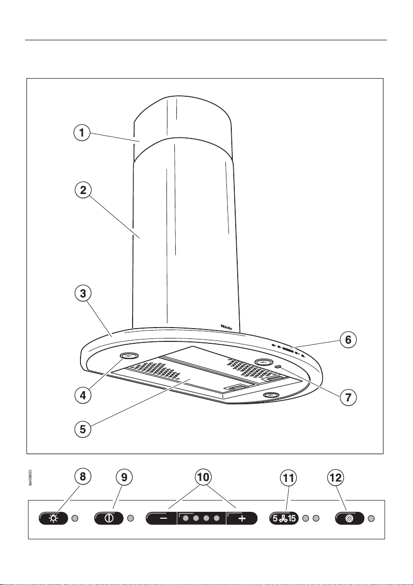
Guide to the appliance
Guide to the appliance
DA 239
8
Page 9

Guide to the appliance
Chimney extension
b
Chimney
c
Canopy
d
e Halogen lamps (3)
f Grease filter
g Controls
h Main power switch
If the hood is not going to be used for
an extended period (during vacation,
etc.), turn the appliance off using the
main power switch.
Light switch
i
The lights can be turned on and off independently of the fan.
l Delayed Shut Down
Pressing this switch activates the Delayed Shut Down feature. The hood will
then automatically shut off after 5 or 15
minutes.
Grease filter switch
m
The lamp beside the grease filter
switch will light when the grease filters
need to be cleaned.
This switch is also used to program
and monitor the Filter Operating Hours.
On/Off switch
j
Press this switch to turn the fan on or
off.
– / + switch
k
Four fan speeds are available to suit
the ventilation needs of your kitchen.
9
Page 10

Functional description
Functional description
The hood draws the air in through a
grease filter and then directs it into the
exhaust ductwork.
The hood comes with a non-return exhaust valve that is placed inside the
ductwork during the installation procedure. This valve automatically closes
when the hood is turned off so that no
exchange of outside air and room air
can occur. When the hood is turned on,
the air pressure of the exhaust fan automatically opens the valve, allowing the
inside air and odors to be vented outside.
10
Page 11

Operation
Main power switch
In order for the hood to operate, the
main power switch must be set to “I”. If
the hood is turned off using this switch,
the settings in use at that time will be
active when it is once again turned on.
Turning on the fan
Press the On/Off button.
Its corresponding lamp will illuminate,
and the fan will operate at speed “2“.
Operation
Selecting a fan setting.
Four fan speeds are available to suit
the ventilation needs of your kitchen.
A low or medium setting is generally
sufficient for normal cooking. Higher
settings are recommended for strong
odors or heavy smoke.
If the hood is turned off using the Main
power switch or after a power failure, it
will operate at the last selected speed
when it is once again turned on.
Turning on the Halogen lights
The lights can be turned on and off independently of the fan.
Press the light switch.
The indictor lamp to the right of the
switch will be lit whenever the lights are
turned on.
Select the desired fan speed by
pressing the – or + switch.
– lowers the fan speed
+ increases the fan speed
The left lamp indicates the lowest
speed, while the right most lamp indicates that the highest speed has been
selected.
11
Page 12

Operation
Activating the Delayed Shut
Down feature.
If odors or smoke remain in the kitchen
after cooking has been completed, the
Delayed Shut Down feature can be selected to allow the hood to continue running for either 5 or 15 minutes.
Set the time interval as follows:
Press once = 5 minute delay
(left indicator lights)
Press twice = 15 minute delay
(right indicator lights)
Press three times = Delayed Shut
Down feature is cancelled.
Turning off the hood
Turn the fan off by pressing the
On/Off button.
The hood should only be turned off
using the Main Power switch if it will not
be used for an extended period (during
vacations for example).
Automatic Safety Shut off
The fan will be turned off automatically
10 hours after the last switch was activated. The Halogen lamps however, will
remain on.
Press the On/Off button to turn the
fan back on.
12
Page 13

Operation
Grease filter operating hours
An internal timer monitors the hours of
fan operation and will light the lamp
above the Grease filter switch to notify
you when the filters need cleaning.
Once the filters have been cleaned, the
timer must be reset as follows:
Press and hold the Grease filter
switch for 4 seconds.
The indicator lamp will go out when the
timer has been reset.
Checking grease filter usage
The percentage of programmed operating hours that the filter has been used
can be displayed as follows:
Turn on the fan.
Press the Grease filter switch.
The number of indicator lamps flashing
on the –/+ switch shows the percentage of programmed hours that the filter
has been used.
1 lamp = 25 %
2 lamps = 50 %
3 lamps = 75 %
4 lamps = 100 %
This value will remain stored in memory
in the event of a power failure.
13
Page 14

Operation
Changing the grease filter hour meter.
The amount of operating time before a
reminder to clean the filters is displayed can be changed to suit individual cooking habits. The timer is factory
preset for 30 hours.
Settings of 20, 30, 40 or 50 hours are
possible.
If your cooking consists of a great deal
of pan or deep fat frying, set the hood
for 20 hours.
To change the setting:
Turn off the fan using the On/Off
switch (not the Main Power switch).
Press the Delayed Shut Down and
Grease Filter switch simultaneously.
The grease filter lamp and one of the
– /+ lamps will flash.
Select the desired reminder time by
pressing the – or + switch.
The lit indicator lamp shows the selected reminder time:
1st lamp = 20 hours
2nd lamp = 30 hours
3rd lamp = 40 hours
4th lamp = 50 hours
14
Store the selection by pressing the
Grease Filter switch.
If your selection is not stored within
4 minutes previous, the hood will revert to using the old setting.
Page 15

Cleaning and care
Before servicing or cleaning the
hood, disconnect it from the power
supply by either removing the fuse,
unplugging it, or manually “tripping”
the circuit breaker.
Cleaning the casing
The casing can be cleaned using a
mild solution of water and dishwashing
detergent. Dry with a soft cloth.
Never use abrasive cleaners, scouring pads, steel wool or caustic
(oven) cleaners to clean the hood.
will damage the surface.
They
A mild, non-abrasive stainless steel
cleaner can also be used to clean the
hood.
Cleaning and care
Grease filters
The reusable metal grease filters will
absorb any grease, dust, or other solid
particles that are pulled into them by
the fan.
The filters should be cleaned every 3–4
weeks, or whenever the grease filter indicator lamp illuminates.
Continued operation with dirty
grease filters is dangerous. They
could ignite and cause personal injury and property damage.
To release the filters, press the latches toward the middle of the filters.
Remove the filters.
15
Page 16

Cleaning and care
To clean the grease filters:
By hand - use a scrub brush in hot
water with a mild detergent.
In a dishwasher - place the grease filters in the lower basket.
Depending on the detergent, cleaning the grease filters in a dishwasher may cause permanent discoloration of the filter surface.
Performance of the filter will be unaffected, however.
After cleaning, the filters can be
dried by placing them on a towel or
other absorbent surface.
While the filters are removed, clean
any dirt or grease from the filter casing to prevent the risk of fire.
Before replacing the filters, make
sure that the latches are facing
down. If you inadvertently install a filter upside down, insert a small
screwdriver into the slit along its
edge to disengage it from the casing.
Once the filters have been replaced,
reset the timer by pressing and holding the Grease filter switch until the
indicator lamp goes out.
16
Page 17

Cleaning and care
Changing the light bulbs
Before changing the light bulbs, disconnect the hood from the power
supply by either removing the fuse,
unplugging it, or manually “tripping”
the circuit breaker.
When in use the halogen bulbs
become extremely hot, and they
can burn your hands. Do not attempt to change the bulbs until they
have had sufficient time to cool
down.
Do not touch the bulb surface when
changing the bulb. Fingerprints or
body oils deposited on the bulb will
decrease the life of the bulb. Please
follow the bulb manufacturer’s in-
structions.
To change a bulb:
Remove the outer ring, b.
Support the glass, d, while detach-
ing the circlip
the glass fall out.
Pull the old bulb, e,out of its socket
and replace it with a new one.
Reinstall the glass, circlip and outer
ring.
. Be careful not to let
c
Never use the lights without the
glass installed. The glass is specially made to filter harmful light
rays.
17
Page 18

After Sales Service
After Sales Service
If a problem arises that you cannot
remedy yourself, please contact the
nearest Miele Service Department.
Phone numbers and addresses are
listed on the back cover.
When contacting the Service Department, please have the Model and Serial No. of the appliance available. They
can be found on the data label that is
visible upon removal of the grease filters.
18
Page 19

Electrical connection and Technical data
Electrical connection and Technical data
Electrical Connection
The hood comes equipped with a
5 ft power cord for connection to a
120 VAC, 60 Hz power supply.
Verify that the information on the data
plate (located behind the grease filters)
matches your electrical supply before
installing the hood.
Technical data
Maximum load. . . . . . . . . . . . . . . 410 W
Light . . . . . . . . . . . . . . . . . . . . 3 x 20 W
Voltage . . . . . . . . . . . . . . . . . . 120 VAC
Frequency . . . . . . . . . . . . . . . . . . 60 Hz
Fuse rating . . . . . . . . . . . . . . . . . . 15 A
Important
The power cord wires are colored as follows:
Green/yellow = ground
Blue = neutral
Brown = live
CAUTION:
Ensure that power supply is OFF
during installation.
If you have any questions as to how
to connect this hood to your building power supply, please call Miele
Appliances or consult a licensed
electrician.
WARNING
THIS APPLIANCE MUST BE
GROUNDED
Fan
Values derived using 6" (150 mm)
ducting and EN 61591 test procedures.
Settings 1 – 3. . . . . . . . . 210 – 430 cfm
(360 – 730 m
Setting 4 . . . . . . . . . . . . . . . . . 495 cfm
(840 m
unrestricted flow . . . . . . . . . . . 560 cfm
(950 m
3
/h)
3
/h)
3
/h)
19
Page 20

Appliance dimensions
Appliance dimensions
DA 239
S = The minimum allowable distance
between the top of the cooking surface
and the bottom of the hood
H = Height of installed hood
1
Adjustable from 32
/2 " - 42 1/8"
(825 – 1070 mm)
"A", the distance between the top edge
of the chimney and the ceiling must be
at least
7
/8" (20mm) to allow for the in-
stallation of the chimney.
= Cut out area in wall or ceiling for
entrance of 6" (150 mm) ductwork.
Metric Conversion table
25 mm . . . . . . . . . . . . . . . . . . . . 1"
3
95 mm . . . . . . . . . . . . . . . . . . 3
110 mm . . . . . . . . . . . . . . . . . . 4
250 mm . . . . . . . . . . . . . . . . . . . 9
270 mm . . . . . . . . . . . . . . . . . . 10
308 mm . . . . . . . . . . . . . . . . . . 12
350 mm . . . . . . . . . . . . . . . . . 13
500 mm . . . . . . . . . . . . . . . . . 19
510 mm . . . . . . . . . . . . . . . . . 20
805 mm . . . . . . . . . . . . . . . . . 31
850 mm . . . . . . . . . . . . . . . . . 33
/4"
5
13
11
1
11
1
/2 "
/16"
7
/8"
5
/8"
1
/8"
/16"
/16"
/16"
/16"
20
Page 21

Installation
Do not install this hood over any appliance that burns solid fuel.
minimum distance allowed be-
The
tween the top of the cooking surface and the bottom of the hood (S)
is:
18 inches (45 cm) when installed
above an electric cooktop or;
26 inches (65 cm) when installed
above a gas cooktop.
26 inches (65 cm) is recommended for
all installations in order to allow more
work space under the hood.
Installation
The majority of the weight of the installed Ventilation System will be
supported by the motor assembly.
Its mounting bracket must be firmly
attached to the stud framing
the drywall. If studs are not located
in the required locations, a plywood
backing (min.
spanning at least two studs
installed. Failure to adequately support the weight as stated may result
in the Ventilation System falling off
the wall, thereby causing personal
injury and property damage.
1
/2” (13mm) thick)
behind
must be
Please read these installation instructions completely before attempting to install the hood.
Example:
To install a plywood backing board
Determine and mark the location of
the motor assembly as outlined in
“Attaching the hood and motor assembly to the wall.”
Mark a horizontal line 3” above and
9” below the mounting screw locations.
21
Page 22

Installation
Find the studs to the left and right of
the mounting location by tapping the
wall or using a stud finder.
Mark the center of each of the studs
with a vertical line.
Be careful not to damage any wiring
or plumbing that may be located behind the wall. Make sure that the
power supply to the area being
worked in has been turned off at the
breaker panel before cutting into
the wall.
Cut out the drywall along the marked
lines and replace it with plywood of a
1
matching thickness (min.
/2” thick).
Tape the joints and refinish the wall.
Proceed to “Attaching the hood and
motor assembly to the wall” to complete the installation.
If plywood backing is not needed, proceed to “Attaching the hood and motor
assembly to the wall.”
Attaching the hood and motor
assembly to the wall
The Chimney and Chimney extension
are attached to the wall using 2 retaining plates.
The motor assembly is attached separately using four supplied screws.
22
To layout the locations for the plates
and motor assembly:
Draw a vertical line, centered on the
cooktop, on the wall where the hood
will be installed.
Mark the location of the 2 motor assembly support screws S + 10
(260 mm) above the cooktop, and
15
/16" (125 mm) off of the centerline
4
1
in each direction.
Layout the location of the lower re-
taining plate screw directly on the
centerline, S + 19
1
/2" (495 mm)
above the cooktop.
/4 "
Page 23

Hold the upper retaining plate flush
against the ceiling so that the centerline passes through the notch on its
lower edge. Making sure the plate is
level, mark the location of the 2
mounting screws.
Installation
(5 mm) so the motor can hang on
them.
Inserting the
Non-return exhaust valve
Drill the 3 marked holes for the
upper and lower retaining plates
using a
then press the supplied wall anchors
into the holes.
Screw the upper and lower retaining
plates securely to the wall.
Fasten the bottom motor assembly
bracket loosely to the wall. Allow the
screw heads to protrude about
5
/16" (8 mm) diameter bit,
1
/4"
Place the Non-return exhaust valve
into the exhaust connection at the
top of the motor assembly so that the
flaps open in the "up" direction.
Rotate the valve slightly to the left to
lock it in place.
23
Page 24

Installation
Attaching the Motor assembly
Place the upper holes of the Motor
assembly over the 2 mounting
screws in the wall.
Making sure the assembly is level,
drill through the 2 remaining holes on
the edge of the mounting bracket
using the
Remove the bracket and press the
wall anchors into the holes. Re-hang
the motor bracket.
Secure the assembly to the wall
using the 2 top screws only.
5
/16" (8 mm) diameter bit.
24
Page 25

Installation
Attaching the canopy
Hang the Canopy from the Motor assembly by placing the holes at the
rear of the plate over the hooks on
the lower edge of the assembly as
shown in the above illustration. Be
careful not to pinch the wires.
Connecting the Exhaust duct
Connect the ductwork to the exhaust
connection using whatever means
are appropriate for the type of ductwork being installed (hose clamp,
duct tape, etc.).
Direct the duct through the back wall
or the ceiling.
Electrical connection
Secure the Canopy by guiding the 2
remaining screws through the locking plate and the holes in the motor
assembly (see illustration). Tighten
the screws.
Connect the plug between the Canopy and the Motor assembly.
Plug in the power cord.
25
Page 26

Installation
Installing the Chimney extension
The chimney extension is used to allow
the hood to be installed at various distances from the ceiling.
Carefully ease apart the sides of the
Chimney extension and hook it behind the top retaining plate.
Peel back the foil from the tape on
the protective covers and stick the
covers on the sides of the Chimney
extension. This will protect the finish
of the extension during the rest of
the installation process.
Push the extension flush against the
ceiling and, using two of the small
machine screws, attach it to the top
retaining plate
Cover the heads of the screws with
the supplied caps.
26
Page 27

Installing the Chimney
Carefully ease apart the sides of the
Chimney and slide it over the Chimney extension. Hook it behind the extension and both retaining plates.
Hold it high enough to clear the top
of the Canopy to avoid scratches.
Slide the Chimney down so that it
sits at least
nopy plate and adjust it as necessary.
3
/8" (1 cm) inside the Ca-
Installation
Remove the grease filters.
Adjust the incline of the Canopy by
using the screw located on its’ interior. Tighten it as much as necessary
to level the front of the plate.
Reinsert the grease filters.
Pull the protective covers off of the
Chimney extension.
Secure the Chimney to the motor assembly and lower retaining plate
using the remaining machine
screws.
Cover the heads of the screws with
the supplied caps.
27
Page 28

Air extraction
Air extraction
Danger of toxic fumes.
Gas cooking appliances release
carbon monoxide that can be harmful or fatal if inhaled. The exhaust
gases extracted by the hood
should be vented outside of the
building
Do not terminate the exhaust ducts
in attics, garages, crawlspaces, etc.
Please read and follow the "Warning
and Safety Instructions“ to reduce the
risk of personal injury, and follow all local
building codes when installing the hood.
only.
Exhaust ducting and connections
– The ducting should be as short and
straight as possible, and the number
of sharp bends should be minimized.
– For most efficient air extraction, the
diameter of the ductwork should not
be less than 6" (150 mm). Use of flat
ducts also reduces the air extraction
efficiency.
– Noise levels of the hood will increase
if flat ducts or round ducts of less
than 6" (150 mm) in diameter are
used.
WARNING
To reduce the risk of fire, Use only
metal ductwork.
CAUTION
To reduce risk of fire and to properly
exhaust air, be sure to duct air outside - Do not vent exhaust air into
spaces within walls or ceilings or
into attics, crawl spaces, or garages.
– Where the ductwork is horizontal, it
must slope away from the hood at
least 1/8" per foot (1cm per meter) to
prevent condensation dripping into
the appliance.
– If the exhaust is ducted through an
outside wall, a Miele Telescopic Wall
Vent can be used.
– If the exhaust is ducted into an inac-
tive flue, the air must be expelled
parallel to the flow direction of the
flue.
28
Page 29

Never connect an exhaust hood to
an active chimney, dryer vent, vent
flue, or room venting ductwork.
Seek professional advice before
connecting an exhaust hood vent to
an existing, inactive chimney or
vent flue.
Ductwork with a diameter of less
than 6" (150 mm) should only be
used when absolutely necessary.
As duct diameter decreases, the
hoods performance and sound levels will be affected.
Note:
If the ductwork runs through rooms,
ceilings, garages, etc. where temperature variations exist, it may need to be
insulated to reduce condensation. In
some cases, a condensate trap may
also be required.
Air extraction
29
Page 30

Page 31

Page 32

Alteration rights reserved / 001 USA - 5098
This paper is made from cellulose which was bleached without the use of chlorine.
 Loading...