

Page 1
Produktgruppe 522 Umbau- und Montageanweisung
1 von 24 M.-Nr. 07724460
16.06.2010 Diese Unterlagen dürfen ohne unsere Genehmigung weder vervielfältigt noch Dritten zugänglich gemacht werden. Eigentumsrechte vorbehalten.
PT 8251, PT 8253, PT 8331, PT 8333, PT 8401, PT 8403, PT 8501, PT 8503, PT 8801, PT 8803
x
de
ni
sv
Montageanweisung
Modul BSS 19/20
Spitzenlastabschaltung
Montage-instructie moduul
BSS 19/20 uitschakeling bij
piekbelasting
Monteringsanvisning modul
BSS 19/20 effekttoppsbrytare
en
da
it
Fitting instructions Module BSS 19/20 Peak-load cut-out
Monteringsanvisning
modul BSS 19/20
spidsbelastningsafbrydelse
Istruzione di montaggio modulo
BSS 19/20 disinserzione carico
massimo di punta
fr
no
es
Notice de montage du
module BSS 19/20 délestage
Monteringsveiledning for
modul BSS 19/20 til
toppbelastningsmodul for
oppvarming
Instrucciones de montaje del
módulo BSS 19/20
Desconexión por carga de pico
el
Οδηγία τοποθέτησης μονάδας
BSS 19/20 διακοπής λόγω
φορτίου αιχμής
am
Installation Instructions BSS 19/20 (Peak Load
Cut-Out) Module
Page 2
1
Produktgruppe 522 Umbau- und Montageanweisung
2 von 24 M.-Nr. 07724460
16.06.2010 Diese Unterlagen dürfen ohne unsere Genehmigung weder vervielfältigt noch Dritten zugänglich gemacht werden. Eigentumsrechte vorbehalten.
x
Page 3

Produktgruppe 522 Umbau- und Montageanweisung
3 von 24 M.-Nr. 07724460
16.06.2010 Diese Unterlagen dürfen ohne unsere Genehmigung weder vervielfältigt noch Dritten zugänglich gemacht werden. Eigentumsrechte vorbehalten.
de
Benötigte Teile
x
Anzahl M.-Nr. Benennung
1 07738640
oder
1 07738650
Hinweis
Diese Umbauarbeiten dürfen grundsätzlich nur von einer Elektrofachkraft (fachliche Ausbildung, Fachkenntnisse und
Facherfahrungen, zeitnahe berufliche Tätigkeit) unter Berücksichtigung der gültigen Sicherheitsbestimmungen
durchgeführt werden.
Für die Instandsetzung, Änderung, Prüfung und Wartung elektrischer Geräte sind die entsprechenden gesetzlichen
Grundlagen, Unfallverhütungsvorschriften, die gültigen Normen, die der Sicherheit dienen, sowie die am Aufstellungsort
gültigen Vorschriften der Energieversorgungsunternehmen zu beachten.
Umbausatz BSS 19 Spitzenlastabschaltung PT 8251 – PT 8333,
PT 8501 – PT 8503
Umbausatz BSS 20 Spitzenlastabschaltung PT 8401 – PT 8403,
PT 8801 – PT 8803
Gefahr!
Auch bei ausgeschaltetem Gerät kann Netzspannung an Bauteilen anliegen!
Deshalb ist, bevor Wartungs-, Instandsetzungs- und Umbauarbeiten am Gerät durchgeführt werden, eine sichere
Netztrennung von allen aktiven, spannungsführenden Leitungen sowie anschließend eine Messung der
Spannungsfreiheit erforderlich!
Grundsätzlich muss eine allgemeine Sichtprüfung durchgeführt werden.
Ein nicht fachgerechter Umbau kann zu einer Gefährdung führen (Brand, elektrischer Schlag usw.).
Gefahr!
Die Schutzleiterfunktion kann durch einen fehlerhaften Gehäusezusammenbau außer Kraft gesetzt werden.
Die Schutzleiterfunktion ist bei Montage der Gehäuseteile wieder herzustellen.
Elektrische Sicherheitsprüfung durchführen.
Hinweis
Der Montagesatz M.-Nr. 07738640 für PT 8251 – PT 8333, PT 8501 – PT 8503 enthält:
Der Montagesatz M.-Nr. 07738650 für PT 8401 – PT 8403, PT 8801 – PT 8803 enthält:
• 1 Kabelbaum 55X-K1/81-K1/73-X3
• 1 Relais K1/81
• 1 Relais 2K1/73
• 1 Halter Relais
• 3 Linsenschraube 4x10
• 1 Verbindungsdraht braun AWG 20x90
• 1 Kabelhalter 200x4,8
• 1 Kabelverschraubung M20x1,5
• 1 Sechskantmutter M20x1,5
• Diese Montageanweisung “Montageanweisung Modul BSS 19/20 Spitzenlastabschaltung”, M.-Nr. 07724460
Liste der Abbildungen:
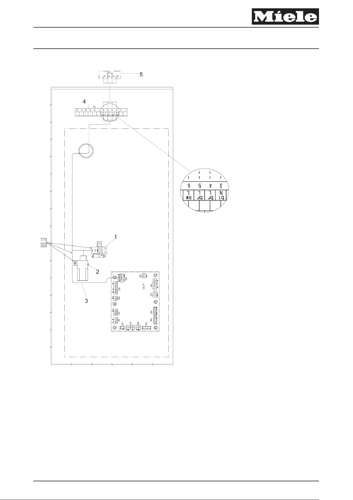
– Abb. 1, Montage Relais und Kabelverschraubung
Page 4
Produktgruppe 522 Umbau- und Montageanweisung
4 von 24 M.-Nr. 07724460
16.06.2010 Diese Unterlagen dürfen ohne unsere Genehmigung weder vervielfältigt noch Dritten zugänglich gemacht werden. Eigentumsrechte vorbehalten.
– Die Maschine vom Elektronetz trennen und gegen Wiedereinschalten sichern.
– Gerätedeckel abbauen.
– Abdeckblech Elektroanschluss an der Rückseite der Maschine abbauen.
x
bl br gn ge gr or rs rt sw vi ws
blau braun grün gelb grau orange rosa rot schwarz violett weiß
Tabelle 1: Kabelfarben
Achtung!
Last- und Steuerstrom Kabelbäume sind getrennt voneinander zu verlegen, um Störsignale in den Steuerleitungen zu
vermeiden (Elektromagnetische Verträglichkeit).
Achtung!
Überschüssige Kabellängen gegenläufig verlegen, um Antennenwirkung bei Leitungen zu vermeiden.
– Das Relais K1/81 (Abb. 1, Pos. 1) und Halter Relais auf dem Geräteträger mit 2 x Linsenschraube 4x10 in den
vorhandenen Löchern festschrauben.
– Das Relais 2K1/73 (Abb. 1, Pos. 2) auf dem Geräteträger mit 1 x Linsenschraube 4x10 in das vorhandene Loch
festschrauben.
– Kabelbaum 55X-K1/81-K1/73-X3 (Abb. 1, Pos. 3) auf dem Geräteträger durch die Kabeldurchführung zur Klemmleiste
X3 (Abb. 1, Pos. 4) verlegen.
– Kabelbaum 55X-K1/81-K1/73-X3 an den montierten Relais und an dem Anschluss EZL 371 – 55X anschließen.
– Kabelbaum 55X-K1/81-K1/73-X3 an der Klemmleiste X3 (Abb. 1, Pos. 4) anschließen. Schaltplan, Kabelfarbe und
Bedruckung “5“am braunen Kabel beachten, siehe Abb.1, Pos. 4.
– Kabelbaum 55X-K1/81-K1/73-X3 mit Kabelhalter 200x4,8 am Kabelbaum im Bereich der Netzanschlussklemme
befestigen.
– Das vorgestanzte Loch für die externe Spitzenlastabschaltung in der Verbindungsleiste (Geräterückwand) öffnen.
– Die Kabelverschraubung M20x1,5 für die externe Spitzenlastabschaltung an der Verbindungsleiste (Geräterückwand)
festschrauben.
– Externe Spitzenlastabschaltung (Abb. 1, Pos. 5) nach den Angaben des Herstellers der Spitzenlastabschaltung an
der Klemmleiste X3 (Abb. 1, Pos. 4) anschließen.
x
Achtung!
Wird keine externe Spitzenlastabschaltung an der Klemmleiste X3 angeschlossen, ist mit dem Verbindungsdraht braun
eine Brücke zwischen Pin 4 und Pin 5 herzustellen.
– Probelauf durchführen.
– Abdeckblech Elektroanschluss an der Rückseite der Maschine anbauen.
– Gerätedeckel anbauen.
– Elektrische Sicherheitsprüfung durchführen.
– Die Maschine am Elektronetz anschließen.
x
Hinweis
Die Freigabe für Spitzenlast in den Programmen überprüfen.
de
Page 5

Produktgruppe 522 Umbau- und Montageanweisung
5 von 24 M.-Nr. 07724460
16.06.2010 Diese Unterlagen dürfen ohne unsere Genehmigung weder vervielfältigt noch Dritten zugänglich gemacht werden. Eigentumsrechte vorbehalten.
en
Parts required
x
Quantity Mat. no. Designation
1 07738640
or
1 07738650
Note
This service and repair work should only be carried out by a suitably qualified electrician (with specialist training,
knowledge and experience, and recent related work experience) in accordance with all appropriate local and national
safety regulations.
Servicing, modification, testing and maintenance of electrical appliances should only be carried out in accordance
with all appropriate legal requirements, accident prevention regulations and valid standards. All regulations of the
appropriate utility supply companies and standards relating to safety (not limited to electrical safety) are to be complied
with.
Conversion kit BSS 19 - Peak-load cut-out - PT 8251 - PT 8333,
PT 8501 - PT 8503
Conversion kit BSS 20 - Peak-load cut-out - PT 8401 - PT 8403,
PT 8801 - PT 8803
Danger!
Even with the machine switched off, mains voltage may be applied to some components.
Before any service work is commenced, the machine must be disconnected from the mains. Suitable measurements must
be made to ensure that this is the case.
A general visual check should always be carried out.
Incorrect conversion or service work can be dangerous (risk of fire, electric shock, etc.).
Danger!
Correct earthing function can be deactivated if casing parts are incorrectly assembled.
Correct earthing function must be ensured when refitting the casing.
Carry out appropriate electrical safety checks.
Note
The conversion kit Mat. no. 07738640 for PT 8251 - PT 8333, PT 8501 - PT 8503 contains the following:
The conversion kit Mat. no. 07738650 for PT 8401 - PT 8403, PT 8801 - PT 8803 contains the following:
• 1 wiring harness 55X-K1/81-K1/73-X3
• 1 relay K1/81
• 1 relay 2K1/73
• 1 relay holder
• 3 raised-head screws 4 x 10
• 1 connection wire, brown, AWG 20 x 90
• 1 cable holder 200 x 4.8
• 1 cable screw connector M20 x 1.5
• 1 nut M20 x 1.5
• Fitting instructions - Module BSS 19/20 - Peak-load cut-out, Mat. no. 07724460
List of illustrations:
– Fig 1: Fitting relay and cable screw connector
Page 6

Produktgruppe 522 Umbau- und Montageanweisung
6 von 24 M.-Nr. 07724460
16.06.2010 Diese Unterlagen dürfen ohne unsere Genehmigung weder vervielfältigt noch Dritten zugänglich gemacht werden. Eigentumsrechte vorbehalten.
– Disconnect the machine from the electrical mains and ensure power cannot be switched on again in error.
– Remove the machine lid.
– Remove the electrical connection cover on the rear of the machine.
x
bl br gn ge gr or rs rt sw vi ws
Blue Brown Green Yellow Grey Orange Pink Red Black Violet White
Table 1: Wire colours
Warning!
The power and control wiring harnesses must be laid separately in order to avoid interference in the control circuit
(electromagnetic compatibility).
Warning!
Excess cable should be gathered such that current flows in opposite directions and tied in order to avoid any antenna
effect.
– Fit the relay K1/81, Fig. 1, Pos. 1, and relay holder on the component bracket with 2 raised-head screws 4 x 10 in the
existing holes.
– Fit relay 2K1/73, Fig. 1, Pos. 2, on the component bracket with 1 raised-head screw 4 x 10 in the existing hole.
– Lay the wiring harness 55X-K1/81-K1/73-X3, Fig. 1, Pos. 3, on the component bracket through the cable throughfeed
to the terminal strip X3, Fig. 1, Pos. 4.
– Connect the wiring harness 55X-K1/81-K1/73-X3 to the fitted relay and the connection EZL 371 - 55X.
– Connect the wiring harness 55X-K1/81-K1/73-X3 to the terminal strip X3, Fig. 1, Pos. 4. Follow the wiring diagram and
take care to note the wire colours and the "5" printed on the brown wire, Fig. 1, Pos. 4.
– Secure wiring harness 55X-K1/81-K1/73-X3 to the wiring harness in the area of the mains connection terminals with
the cable holder 200 x 4.8.
– Open the pre-cut hole for the external peak-load cut-out in the connection strip (machine rear panel).
– Fit the cable screw connector M20 x 1.5 for the external peak-load cut-out in the connection strip (machine rear
panel).
– Connect the external peak-load cut-out, Fig. 1, Pos. 5, in accordance with the manufacturer's instructions, to the
terminal strip X3, Fig. 1, Pos. 4.
x
Warning!
If no external peak-load cut-out is connected to terminal strip X3, the brown connection wire must be used to make a
bridge between pin 4 and pin 5.
– Carry out a test run.
– Refit the electrical connection cover on the rear of the machine.
– Refit the machine lid.
– Carry out appropriate electrical safety checks.
– Reconnect the machine to the electric mains supply.
x
Note
Check that the peak-load cut-out function is activated in the machine programmes.
en
Page 7

Produktgruppe 522 Umbau- und Montageanweisung
7 von 24 M.-Nr. 07724460
16.06.2010 Diese Unterlagen dürfen ohne unsere Genehmigung weder vervielfältigt noch Dritten zugänglich gemacht werden. Eigentumsrechte vorbehalten.
fr
Pièces nécessaires
x
Nombre Mat.-Nr. Désignation
1 07738640
ou
1 07738650
Remarque
Les travaux d'adaptation doivent être effectués exclusivement par un technicien qualifié (c'est à dire ayant suivi une
formation spécifique et disposant de connaissances et d'expériences récentes dans le domaine) respectant les
prescriptions de sécurité en vigueur.
La réglementation en vigueur, les prescriptions de prévention des accidents, les normes applicables de sécurité sur le lieu
d'installation ainsi que les prescriptions de la compagnie d'électricité doivent impérativement être respectées pour la
réparation, la modification, le contrôle et la maintenance des appareils électriques.
Jeu d'adaptation BSS 19 délestage PT 8251 – PT 8333,
PT 8501 – PT 8503
Jeu d'adaptation BSS 20 délestage PT 8401 – PT 8403,
PT 8801 – PT 8803
Danger !
Même si l'appareil est déconnecté, les composants peuvent présenter une tension résiduelle.
C'est pourquoi avant d'effectuer tout entretien, réparation ou modification, il est nécessaire de débrancher tous les câbles
actifs et sous tension et d'effectuer une mesure pour s'assurer de l'absence de tension résiduelle !
Un contrôle visuel général doit impérativement être effectué.
Une modification non effectuée dans les règles peut avoir des conséquences dangereuses (incendie, électrocution, etc.)
Danger !
En cas de remontage de la carrosserie incorrect, le fonctionnement de la mise à la terre de l'appareil risque d'être
désactivé.
Le fonctionnement de la mise à la terre doit être assuré après le montage des pièces de la carrosserie.
Effectuer un contrôle de sécurité électrique.
Remarque
Le jeu de montage M.-Nr. 07738640 pour PT 8251 – PT 8333, PT 8501 – PT 8503 contient :
Le jeu de montage M.-Nr. 07738640 pour PT 8401 – PT 8403, PT 8801 – PT 8803 contient :
• 1 toron 55X-K1/81-K1/73-X3
• 1 relais K1/81
• 1 relais 2K1/73
• 1 support de relais
• 3 vis à tête ronde 4x10
• 1 fil de liaison brun AWG 20x90
• 1 serre-câbles 200x4,8
• 1 vissage de câble M20x1,5
• 1 écrou à six pans M20x15
• La présente notice de montage “Notice de montage du module BSS 19/20 délestage ”, M.-Nr. 07724460
Liste des croquis :
– Croquis 1, Montage des relais et vissage des câbles
Page 8

Produktgruppe 522 Umbau- und Montageanweisung
8 von 24 M.-Nr. 07724460
16.06.2010 Diese Unterlagen dürfen ohne unsere Genehmigung weder vervielfältigt noch Dritten zugänglich gemacht werden. Eigentumsrechte vorbehalten.
– Débrancher la machine du secteur et protéger contre une remise en marche accidentelle.
– Démonter le couvercle.
– Déposer le panneau d'habillage couvrant le raccordement électrique à l'arrière de la machine.
x
bl br gn ge gr or rs rt sw vi ws
bleu brun vert jaune gris orange rose rouge noir violet blanc
Tableau 1: Couleurs des câbles
Attention !
Les torons de courant de charge et de commande doivent être posés séparément pour éviter les signaux parasites dans
les fils de commande (compatibilité électromagnétique).
Attention !
Poser les excédents de câble en sens inverse pour éviter un effet d'antenne.
– Visser le relais K1/81 (croquis 1, pos. 1) et le support de relais sur le support d'organes avec 2 vis à tête ronde 4x10
insérées dans les trous existants.
– Visser le relais 2K1/73 (croquis 1, pos. 2) sur le support d'organes avec 1 vis à tête ronde 4x10 insérée dans le trou
existant.
– Poser le toron 55X-K1/81-K1/73-X3 (croquis 1, pos. 3) à travers le passage de câbles sur le support d'organes, borne
X3 (croquis 1, pos. 4) .
– Raccorder le toron 55X-K1/81-K1/73-X3 au relais monté et au raccordement EZL 371 – 55X.
– Raccorder le toron 55X-K1/81-K1/73-X3 à la borne X3 (croquis 1, pos. 4). Respecter le schéma électrique et
l'inscription “5“ sur le câble brun, voir croquis 1, pos. 4.
– Fixer le toron 55X-K1/81-K1/73-X3 avec le serre-câble 200x4,8 sur le toron au niveau de la borne de raccordement
réseau.
– Ouvrir le trou prépercé pour le délestage externe dans la barre de liaison (arrière de l'appareil).
– Visser le vissage de câble M20x1,5 pour le délestage externe sur la barre de liaison (arrière de l'appareil).
– Raccorder le délestage externe (croquis 1, pos. 5) à la borne X3 (croquis 1, pos. 4) en suivant les indications du
fabricant du délesteur.
x
Attention !
Si aucun délestage n'est raccordé à la borne X3, shunter les bornes 4 et 5 avec le fil de raccordement.
– Effectuer un test de fonctionnement.
– Poser le panneau d'habillage couvrant le raccordement électrique à l'arrière de la machine.
– Monter le couvercle.
– Effectuer un contrôle de sécurité électrique.
– Raccorder la machine à l'alimentation.
x
Remarque
Vérifier que le délestage est bien autorisé dans les programmes.
fr
Page 9

Produktgruppe 522 Umbau- und Montageanweisung
9 von 24 M.-Nr. 07724460
16.06.2010 Diese Unterlagen dürfen ohne unsere Genehmigung weder vervielfältigt noch Dritten zugänglich gemacht werden. Eigentumsrechte vorbehalten.
ni
Benodigde onderdelen
x
aantal Mat.-nr. Benaming
1 07738640
of
1 07738650
Opmerking
Deze ombouwwerkzaamheden mogen in principe alleen door een vakman, met inachtneming van alle geldende
veiligheidsvoorschriften worden uitgevoerd.
Voor reparatie, wijziging, controle en onderhoud van elektrische apparaten dient men de desbetref fende wetten,
veiligheidsvoorschriften en de geldende normen in acht te nemen.
Ombouwset BSS 19 uitschakeling bij piekbelasting PT 8251 – PT 8333,
PT 8501 – PT 8503
Ombouwset BSS 20 uitschakeling bij piekbelasting PT 8401 – PT 8403,
PT 8801 – PT 8803
Pas op!
Ook als het apparaat uitgeschakeld is, kunnen onderdelen onder spanning staan!
Daarom is het noodzakelijk, voordat er onderhouds-, reparatie- en ombouwwerkzaamheden aan het apparaat uitgevoerd
worden, alle actieve kabels, die onder spanning staan, spanningsvrij te maken en vervolgens te meten of de kabels
spanningsvrij zijn!
Er dient een algemene optische controle plaats te vinden.
Een niet deskundige ombouw kan gevaarlijk zijn (brand, elektrische schok enz.).
Pas op!
De aarddraad kan door een verkeerde montage van was- en droogautomaten buiten werking gesteld worden.
De aarddraad moet bij de montage van het huis weer in werking gesteld worden.
Controleer de elektrische veiligheid.
Opmerking
De montageset met mat.-nr. 07738640 voor de PT 8251 – PT 8333, PT 8501 – PT 8503 bevat:
De montageset met mat.-nr. 07738650 voor de PT 8401 – PT 8403, PT 8801 – PT 8803 bevat:
• 1 kabelboom 55X-K1/81-K1/73-X3
• 1 relais K1/81
• 1 relais 2K1/73
• 1 relaishouder
• 3 lenskopschroeven 4x10
• 1 verbindingskabel bruin AWG 20x90
• 1 kabelklem 200x4,8
• 1 kabelwartel M20x1,5
• 1 zeskantige moer M20x1,5
• Deze montage-instructie "Montage-instructie moduul BSS 19/20 uitschakeling bij piekbelasting", mat.-nr. 07724460
Overzicht van de afbeeldingen:
– Afb. 1, montage relais en kabelwartel
Page 10

Produktgruppe 522 Umbau- und Montageanweisung
10 von 24 M.-Nr. 07724460
16.06.2010 Diese Unterlagen dürfen ohne unsere Genehmigung weder vervielfältigt noch Dritten zugänglich gemacht werden. Eigentumsrechte vorbehalten.
– Koppel het apparaat los van het elektriciteitsnet en zorg dat het niet ingeschakeld kan worden.
– Demonteer het deksel van het apparaat.
– Demonteer de afdekplaat van de elektrische aansluiting aan de achterkant van het apparaat.
x
bl br gn ge gr or rs rt sw vi ws
Blauw Bruin Groen Geel Grijs Oranje Roze Rood Zwart Paars Wit
tabel 1: Kabelkleuren
Let op!
De kabelbomen voor de belastings- en de stuurstroom moeten gescheiden van elkaar gelegd worden om stoorsignalen in
de stuurkabels te voorkomen (elektromagnetische compatibiliteit).
Let op!
Plaats overbodige stukken kabel tegen de stroom in, om het antenne-effect bij kabels te voorkomen.
– Schroef relais K1/81 (Afb. 1, Pos. 1) en de relaishouder met 2 lenskopschroeven 4x10 in de aanwezige gaten op de
montageplaat voor elektrische onderdelen vast.
– Schroef relais 2K1/73 (Afb. 1, Pos. 2) met 1 lenskopschroef 4x10 in het aanwezige gat op de montageplaat voor
elektrische onderdelen vast.
– Plaats kabelboom 55X-K1/81-K1/73-X3 (Afb. 1, Pos. 3) door de kabelgeleiding naar klemmenstrook X3 (Afb. 1, Pos. 4)
op de montageplaat voor elektrische onderdelen .
– Sluit kabelboom 55X-K1/81-K1/73-X3 op het gemonteerde relais en op aansluiting EZL 371 – 55X aan.
– Sluit kabelboom 55X-K1/81-K1/73-X3 op klemmenstrook X3 (Afb.1, Pos. 4) aan. Let op schakelschema, kabelkleur
en opdruk “5“ op de bruine kabel, zie Afb. 1, Pos. 4.
– Maak kabelboom 55X-K1/81-K1/73-X3 met kabelklem 200x4,8 aan de kabelboom bij de netaanluitingsklem vast.
– Maak het voorgestanste gat voor de externe uitschakeling bij piekbelasting in de verbindingslijst (achterwand van het
apparaat) open.
– Schroef kabelwartel M20x1,5 voor de externe uitschakeling bij piekbelasting op de verbindingslijst (achterwand van
het apparaat) vast.
– Sluit de externe uitschakeling bij piekbelasting (Afb. 1, Pos. 5) volgens de instructies van de fabrikant van deze
schakeling aan op klemmenstrook X3 (Afb. 1, Pos. 4).
x
Let op!
Als er geen externe uitschakeling bij piekbelasting op klemmenstrook X3 aangesloten wordt, moet met de bruine
verbindingskabel een brug tussen pin 4 en pin 5 gemaakt worden.
– Laat het apparaat proefdraaien.
– Monteer de afdekplaat van de elektrische aansluiting op de achterkant van het apparaat.
– Plaats het deksel op het apparaat.
– Controleer de elektrische veiligheid.
– Sluit het apparaat op het elektriciteitsnet aan.
x
Opmerking
De vrijgave voor piekbelasting in de programma's controleren.
ni
Page 11

Produktgruppe 522 Umbau- und Montageanweisung
11 von 24 M.-Nr. 07724460
16.06.2010 Diese Unterlagen dürfen ohne unsere Genehmigung weder vervielfältigt noch Dritten zugänglich gemacht werden. Eigentumsrechte vorbehalten.
da
Nødvendige dele
x
Antal M.-Nr. Betegnelse
1 07738640
eller
1 07738650
Bemærk
Denne montering må principielt kun udføres af en fagmand (faglig uddannelse, fagkundskab og -erfaring samt aktuel
relevant beskæftigelse) under hensyntagen til gældende sikkerhedsbestemmelser.
Ved reparation, ændring, kontrol og vedligeholdelse af elektriske produkter skal lovbestemmelserne, de
ulykkesforebyggende forskrifter, de gældende sikkerhedsnormer for de pågældende produkter og
energiforsyningsselskabets forskrifter gældende for opstillingsstedet overholdes.
Ombygningssæt BSS 19 spidsbelastningsafbrydelse
PT 8251 – PT 8333, PT 8501 – PT 8503
Ombygningssæt BSS 20 spidsbelastningsafbrydelse
PT 8401 – PT 8403, PT 8801 – PT 8803
Risiko!
Også på slukkede maskiner kan der forekomme netspænding på delene!
Inden der foretages vedligeholdelse, reparation eller ombygning, skal alle spændingsførende ledninger derfor være
sikkert afbrudt. Foretag kontrolmåling!
Der skal altid foretages en generel visuel kontrol.
Hvis ombygningen ikke foretages korrekt, er der risiko for brand, elektrisk stød osv.
Risiko!
Hvis kabinettet ikke monteres korrekt, kan jordledningens funktion blive sat ud af kraft.
Jordledningens funktion skal genetableres ved montering af kabinetdelene.
Foretag elektrisk sikkerhedskontrol.
Bemærk
Monteringssæt M.-Nr. 07738640 til PT 8251 – PT 8333, PT 8501 – PT 8503 indeholder:
Monteringssæt M.-Nr. 07738650 til PT 8401 – PT 8403, PT 8801 – PT 8803 indeholder:
• 1 ledningsbundt 55X-K1/81-K1/73-X3
• 1 relæ K1/81
• 1 relæ 2K1/73
• 1 holder til relæ
• 3 skruer 4x10
• 1 brun forbindelsesledning AWG 20x90
• 1 ledningsholder 200x4,8
• 1 kabelforskruning M20x1,5
• 1 møtrik M20x1,5
• Denne monteringsanvisning “Monteringsanvisning modul BSS 19/20 spidsbelastningsafbrydelse”, M.-nr. 07724460
Liste over illustrationer:
– Ill. 1, Montering af relæ og ledningsforskruning
Page 12
Produktgruppe 522 Umbau- und Montageanweisung
12 von 24 M.-Nr. 07724460
16.06.2010 Diese Unterlagen dürfen ohne unsere Genehmigung weder vervielfältigt noch Dritten zugänglich gemacht werden. Eigentumsrechte vorbehalten.
– Afbryd maskinen fra elnettet, og sørg for at sikre den mod genindkobling.
– Afmonter toppladen.
– Afmonter afdækningsplade eltilslutning på bagsiden af maskinen.
x
bl br gn ge gr or rs rt sw vi ws
blå brun grøn gul grå orange rosa rød sort lilla hvid
skema 1: Ledningsfarver
Vigtigt!
Ledningsbundter belastnings- og styrestrøm skal lægges adskilt fra hinanden for at undgå forstyrrende signaler i
styreledningerne (elektromagnetisk støjpåvirkning).
Vigtigt!
Læg overskydende ledningslængder i modsat retning for at undgå antennevirkning på ledningerne.
– Skru relæ K1/81 (ill. 1, Pos. 1) og holder til relæ på komponentpladen med 2 x skruer 4x10 i de eksisterende huller.
– Skru relæ 2K1/73 (ill. 1, Pos. 2) på komponentpladen med 1 x skrue 4x10 i det eksisterende hul.
– Læg ledningsbundt 55X-K1/81-K1/73-X3 (ill. 1, Pos. 3) på komponentpladen gennem ledningsgennemføringen til
klemliste X3 (ill. 1, Pos. 4).
– Tilslut ledningsbundt 55X-K1/81-K1/73-X3 til de monterede relæer og tilslutning EZL 371 – 55X.
– Tilslut ledningsbundt 55X-K1/81-K1/73-X3 til klemliste X3 (ill. 1, Pos. 4). Vær opmærksom Diagram, ledningsfarve og
påtrykningen “5“ på den brune ledning, se ill. 1, Pos. 4.
– Fastgør ledningsbundt 55X-K1/81-K1/73-X3 med ledningsholder 200x4,8 på ledningsbundet i området ved
nettilslutningsklemmen.
– Åbn det forudstansede hul til den eksterne spidbelastningsafbrydelse i forbindelseslisten (maskinens bagvæg).
– Skru ledningsforskruningen M20x1,5 til den eksterne spidbelastningsafbrydelse fast ved forbindelseslisten
(maskinens bagvæg).
– Tilslut den eksterne spidsbelastningsafbrydelse (ill. 1, Pos. 5) til klemliste X3 i overensstemmelse med angivelserne
fra producenten af spidsbelastningsafbrydelsen X3 (ill. 1, Pos. 4).
x
Vigtigt!
Hvis der ikke tilsluttes nogen spidsbelastningsafbrydelse til klemliste X3, skal der etableres en lus mellem pin 4 og pin 5.
– Foretag en prøvekørsel.
– Monter afdækningsplade eltilslutning på bagsiden af maskinen.
– Monter toppladen.
– Foretag en elektrisk sikkerhedskontrol.
– Tilslut maskinen til elnettet.
x
Bemærk
Kontroller, at spidsbelastning er frigivet i programmerne.
da
Page 13

Produktgruppe 522 Umbau- und Montageanweisung
13 von 24 M.-Nr. 07724460
16.06.2010 Diese Unterlagen dürfen ohne unsere Genehmigung weder vervielfältigt noch Dritten zugänglich gemacht werden. Eigentumsrechte vorbehalten.
no
Nødvendige deler
x
Antall M.-nr. Betegnelse
1 07738640
eller
1 07738650
NB!
Dette ombyggingsarbeidet skal kun utføres av kvalifiserte elektrofagfolk som tar hensyn til de gjeldende
sikkerhetsbestemmelser.
For reparasjon, endring, test og vedlikehold av elektriske maskiner skal de overensstemmende lovbestemmelser,
ulykkesforebyggende forskrifter og gjeldende normer som angår sikkerhet samt E-verkets gjeldende forskrifter på
oppstillingsstedet, følges.
Ombygningssett BSS 19 til toppbelastningsmodul for oppvarming
PT 8251 – PT 8333, PT 8501 – PT 8503
Ombygningssett BSS 20 til toppbelastningsmodul for oppvarming
PT 8401 – PT 8403, PT 8801 – PT 8803
Advarsel !
Det kan være spenning i komponentene også når maskinen er frakoblet.
Derfor er det nødvendig å gjøre maskinen spenningsløs og sikre (isolere) alle spenningsførende ledninger før vedlikehold,
reparasjon og ombyggingsarbeid på maskinen utføres. Deretter må det foretas en måling for å kontrollere at spenningen
er avslått.
Det skal gjennomføres en generell og typebasert funksjons- og inspeksjonstest.
Ombygging foretatt av ufaglærte kan føre til fare (brann eller elektrisk støt).
Advarsel !
Jordledningsfunksjonen kan ved feilaktig gjenoppbygging settes ut av kraft.
Jordledningsfunksjonen skal gjenopprettes ved montasje av kabinettdeler.
Gjennomfør elektrisk sikkerhetstest.
NB!
Monteringsettet M.-nr. 07738640 for PT 8251 – PT 8333, PT 8501 – PT 8503 inneholder:
Monteringsettet M.-nr. 07738650 for PT 8401 – PT 8403, PT 8801 – PT 8803 inneholder:
• 1 kabelbunt 55X-K1/81-K1/73-X3
• 1 relé K1/81
• 1 relé 2K1/73
• 1 brakett for relé
• 3 linseskrue 4x10
• 1 ledningsforbindelse, brun AWG 20x90
• 1 kabelholder 200x4,8
• 1 kabelgjennomføring M20x1,5
• 1 sekskantmutter M20x1,5
• “Monteringsveiledning for modul BSS 19/20 toppbelastningsmodul for oppvarming”, M.-nr. 07724460
Liste over illustrasjoner:
– Fig. 1, Montasje av relé og kabelgjennomføring
Page 14

Produktgruppe 522 Umbau- und Montageanweisung
14 von 24 M.-Nr. 07724460
16.06.2010 Diese Unterlagen dürfen ohne unsere Genehmigung weder vervielfältigt noch Dritten zugänglich gemacht werden. Eigentumsrechte vorbehalten.
– Gjør maskinen spenningsløs og sikre at den ikke kobler seg inn igjen.
– Demonter maskindekselet.
– Demonter dekkplaten til elektrotilkoblingen på baksiden av maskinen.
x
bl br gn ge gr or rs rt sw vi ws
blå brun grønn gul grå oransje rosa rød sort fiolett hvit
tabell 1: Kabelfarger
Viktig!
Effekt- og styrestrøm-kabelbuntene skal plasseres adskilt fra hverandre for å unngå støysignaler i styreledningene
(elektromagnetisk kompatibilitet).
Viktig!
Legg overskytende kabellengder i hver sin (motgående) retning for å forhindre antennevirkning i ledningene.
– Skru fast relé K1/81 (fig. 1, pos. 1) og brakett for releet på festeplaten med 2 x linseskrue 4x10 i de eksisterende hull.
– Skru fast relé 2K1/73 (fig. 1, pos. 2) på festeplaten med 1 x linseskrue 4x10 i det eksisterende hull.
– Plasser kabelbunt 55X-K1/81-K1/73-X3 (fig. 1, pos. 3) på festeplaten gjennom kabelgjennomføringen til koblingslist
X3 (fig. 1, pos. 4).
– Tilkoble kabelbunt 55X-K1/81-K1/73-X3 til det monterte releet og til tilkoblingen EZL 371 – 55X.
– Tilkoble kabelbunt 55X-K1/81-K1/73-X3 til koblingslist X3 (fig. 1, pos. 4). Ta hensyn til koblingsskjema, kabelfarge og
påtrykt “5“ på brun kabel, se fig. 1, pos. 4.
– Fest kabelbunt 55X-K1/81-K1/73-X3 med kabelholder 200x4,8 på kabelbunten i området til nettilkoblingen.
– Åpne det forstansede hullet for den eksterne toppbelastningsmodulen for oppvarming i tilkoblingslisten (maskinens
bakvegg).
– Skru fast kabelgjennomføring M20x1,5 til den eksterne toppbelastningsmodul for oppvarming til tilkoblingslisten
(maskinens bakvegg).
– Tilkoble den eksterne toppbelastningsmodulen for oppvarming (fig. 1, pos. 5) til koblingslist X3 (fig. 1, pos. 4) i henhold
til produsentens instruks for toppbelastningsmodulen for oppvarming.
x
Viktig!
Hvis ingen ekstern toppbelastningsmodul for oppvarming tilkobles koblingslist X3, skal det lages en bro mellom pin 4 og
pin 5 med den brune ledningsforbindelsen.
– Gjennomfør testkjøring.
– Monter dekkplaten til elektrotilkobling på baksiden av maskinen.
– Monter maskindeksel.
– Gjennomfør elektrisk sikkerhetstest.
– Tilkoble maskinen til strømnettet.
x
NB!
Kontroller frigivelsen for toppbelastningen i programmene.
no
Page 15
Produktgruppe 522 Umbau- und Montageanweisung
15 von 24 M.-Nr. 07724460
16.06.2010 Diese Unterlagen dürfen ohne unsere Genehmigung weder vervielfältigt noch Dritten zugänglich gemacht werden. Eigentumsrechte vorbehalten.
sv
Erforderliga delar
x
Antal M-nr Benämning
1 07738640
eller
1 07738650
Anmärkning
Dessa ombyggnadsarbeten får endast utföras av en elfackman (som har yrkesutbildning och praktisk erfarenhet av
yrket) under beaktande av gällande säkerhetsföreskrifter.
Vid idrifttagande, ändring, kontroll och underhåll av elektriska produkter ska lagstadgade, gällande
säkerhetsföreskrifter och normer samt lokala föreskrifter och bestämmelser gällande strömförsörjningen beaktas.
Ombyggnadssats BSS 19 effekttoppsbrytare PT 8251 – PT 8333,
PT 8501 – PT 8503
Ombyggnadssats BSS 20 effekttoppsbrytare PT 8401 – PT 8403,
PT 8801 – PT 8803
Fara!
Även när produkten är avstängd kan komponenter vara strömförande!
Före underhålls-, installations- och ombyggnadsarbeten måste därför en säker brytning av produkten göras. Därefter ska
en mätning göras för att kontrollera att strömmen är bruten!
Principiellt ska alltid en översiktlig okulär besiktning av produkten och uppställningsplatsen ske.
Vid en felaktig ombyggnad finns risk för brand, elstötar och andra skador.
Fara!
Skyddsledarfunktionen kan sättas ur funktion i tvättmaskinen/torktumlaren p g a en felaktig återmontering.
Skyddsledarfunktionen ska återställas vid monteringen av höljets delar.
Genomför en elektrisk säkerhetskontroll.
Anmärkning
Monteringssatsen med m-nr 07738640 för PT 8251 – PT 8333, PT 8501 – PT 8503 innehåller:
Monteringssatsen med m-nr 07738650 för PT 8401 – PT 8403, PT 8801 – PT 8803 innehåller:
• 1 kabelstam 55X-K1/81-K1/73-X3
• 1 relä K1/81
• 1 relä 2K1/73
• 1 fäste relä
• 3 maskinskruvar med kullrig skalle 4x10
• 1 kopplingstråd, brun AWG 20x90
• 1 buntband 200x4,8
• 1 kabelförskruvning M20x1,5
• 1 sexkantmutter M20x1,5
• Denna monteringsanvisning "Monteringsanvisning modul BSS 19/20 effekttoppsbrytare", m-nr 07724460
Lista över bilder:
– Bild 1, montera relä och kabelförskruvning
Page 16

Produktgruppe 522 Umbau- und Montageanweisung
16 von 24 M.-Nr. 07724460
16.06.2010 Diese Unterlagen dürfen ohne unsere Genehmigung weder vervielfältigt noch Dritten zugänglich gemacht werden. Eigentumsrechte vorbehalten.
– Bryt strömmen till tvättmaskinen/torktumlaren och säkerställ att den inte kan kopplas in oavsiktligt.
– Demontera topplocket.
– Demontera täckplåten från elanslutningens kontakt på maskinens baksida.
x
bl br gn ge gr or rs rt sw vi ws
blå brun grön gul grå orange rosa röd svart lila vit
tabell 1: Kabelfärger
Obs!
Kabelstammarna för belastningsström och styrström ska förläggas skilda från varandra för att undvika störningar i
styrledningarna (elektromagnetisk kompatibilitet).
Obs!
Förlägg överflödiga ledningslängder motlöpande för att undvika antennverkan hos ledningarna.
– Skruva fast reläet K1/81 (bild 1, pos. 1) och dess fäste i de tillgängliga hålen på komponenthållaren med hjälp av två
maskinskruvar med kullrig skalle 4x10.
– Skruva fast reläet 2K1/73 (bild 1, pos. 2) i det tillgängliga hålet på komponenthållaren med hjälp av en maskinskruv
med kullrig skalle 4x10.
– Förlägg kabelstammen 55X-K1/81-K1/73-X3 (bild 1, pos. 3) på komponenthållaren genom kabelgenomföringen till
kopplingssplint X3 (bild 1, pos. 4).
– Anslut kabelstammen 55X-K1/81-K1/73-X3 till de monterade reläerna och till anslutningen EZL 371 – 55X.
– Anslut kabelstammen 55X-K1/81-K1/73-X3 till kopplingsplint X3 (bild 1, pos. 4). Beakta kopplingsschema, kabelfärg
och markeringen "5" på den bruna kabeln, se bild 1, pos. 4.
– Fäst kabelstammen 55X-K1/81-K1/73-X3 med buntband 200x4,8 på kabelstammen i området vid
nätanslutningsplinten.
– Öppna det förstansade hålet för den externa effekttoppsbrytaren i förbindelselisten (maskinens bakstycke).
– Skruva fast kabelförskruvningen M20x1,5 för den externa effekttoppsbrytaren på förbindelselisten (maskinens
bakstycke).
– Anslut den externa effekttoppsbrytaren (bild 1, pos. 5) till kopplingsplint X3 (bild 1, pos. 4) enligt tillverkarens
anvisningar.
x
Obs!
Om ingen extern effekttoppsbrytare ansluts till kopplingsplint X3, ska en brygga skapas mellan stift 4 och stift 5 med hjälp
av den bruna kopplingstråden.
– Gör en testomgång.
– Montera täckplåten från elanslutningens kontakt på maskinens baksida.
– Montera topplocket.
– Genomför en elektrisk säkerhetskontroll.
– Anslut tvättmaskinen/torktumlaren till elnätet.
x
Anmärkning
Kontrollera att effekttoppsbrytaren kan aktiveras i programmen.
sv
Page 17

Produktgruppe 522 Umbau- und Montageanweisung
17 von 24 M.-Nr. 07724460
16.06.2010 Diese Unterlagen dürfen ohne unsere Genehmigung weder vervielfältigt noch Dritten zugänglich gemacht werden. Eigentumsrechte vorbehalten.
it
Pezzi necessari
x
Numero N. d'ord. Denominazione
1 07738640
oppure
1 07738650
Indicazione
Questa modifica può essere eseguita solo da un tecnico qualificato (formazione tecnica, competenza ed esperienza nel
settore, attività professionale recente) nel rispetto delle vigenti norme di sicurezza.
Per la riparazione, la modifica, il controllo e la manutenzione di apparecchiature elettriche devono essere rispettate le
disposizioni legislative generali, la legge sulla prevenzione degli infortuni sul lavoro e le vigenti norme in materia.
Set di modifica BSS 19 disinserzione carico massimo di punta
PT 8251 – PT 8333, PT 8501 – PT 8503
Set di modifica BSS 20 disinserzione carico massimo di punta
PT 8401 – PT 8403, PT 8801 – PT 8803
Pericolo!
I componenti possono essere sotto tensione rete anche ad apparecchio disinserito!
Per questo, prima di eseguire lavori di riparazione, manutenzione o modifica sull'apparecchio, accertarsi che tutti i cavi
attivi, che conducono tensione, siano staccati dalla rete elettrica e misurare l'assenza di tensione ed eseguire
successivamente una misurazione in merito!
Effettuare sempre un controllo visivo generale.
Se la modifica non è eseguita a regola d'arte, può verificarsi una situazione di pericolo (incendio, scossa elettrica, ecc.).
Pericolo!
La funzione di messa a terra può essere resa inefficace a causa dell'assemblaggio difettoso dell'involucro.
Ripristinare la funzione di messa a terra quando vengono rimontati i componenti dell'involucro.
Eseguire un controllo di sicurezza elettrica.
Indicazione
Il set di montaggio n.d'ord. 07738640 per PT 8251 – PT 8333, PT 8501 – PT 8503 comprende:
Il set di montaggio n.d'ord. 07738650 per PT 8401 – PT 8403, PT 8801 – PT 8803 comprende:
• 1 caveria 55X-K1/81-K1/73-X3
• 1 relais K1/81
• 1 relais 2K1/73
• 1 supporto relais
• 3 viti lenticolari 4x10
• 1 filo di collegamento marrone AWG 20x90
• 1 portacavo 200x4,8
• 1 raccordo per cavo M20x1,5
• 1 dado esagonale M20x1,5
• Questa istruzione di montaggio “Istruzione di montaggio modulo BSS 19/20 disinserzione carico massimo di punta”,
n.d'ord. 07724460
Elenco delle figure:
– Fig. 1, montaggio relais e raccordo cavo
Page 18

Produktgruppe 522 Umbau- und Montageanweisung
18 von 24 M.-Nr. 07724460
16.06.2010 Diese Unterlagen dürfen ohne unsere Genehmigung weder vervielfältigt noch Dritten zugänglich gemacht werden. Eigentumsrechte vorbehalten.
– Staccare la macchina dalla rete elettrica e assicurarsi che non possa reinserirsi.
– Smontare il coperchio macchina.
– Smontare la lamiera di copertura allacciamento elettrico sul retro della macchina.
x
bl br gn ge gr or rs rt sw vi ws
blu marrone verde giallo grigio arancione rosa rosso nero viola bianco
tabella 1: Colore dei cavi
Attenzione!
Posare separatamente le caverie corrente di carico e corrente di comando per evitare segnali d'interferenza nelle
condutture di comando (compatibilità elettromagnetica).
Attenzione!
Posare lunghezze cavo in eccesso in modo opposto per evitare l'effetto antenna per le condutture.
– Avvitare il relais K1/81 (fig. 1, Pos. 1) e il supporto relais sul porta-apparecchiature con 2 viti lenticolari 4x10 nei fori
presenti.
– Avvitare il relais 2K1/73 (fig. 1, Pos. 2) sul porta-apparecchiature con 1 vite lenticolare 4x10 nel foro presente.
– Posare la caveria 55X-K1/81-K1/73-X3 (fig. 1, Pos. 3) sul porta-apparecchiature attraverso il passaggio cavo verso la
morsettiera X3 (fig. 1, Pos. 4).
– Allacciare la caveria 55X-K1/81-K1/73-X3 al relais montato ed all'allacciamento EZL 371 – 55X.
– Allacciare la caveria 55X-K1/81-K1/73-X3 alla morsettiera X3 (fig. 1, Pos. 4). Osservare schema elettrico, colore cavo
e stampa “5“sul cavo marrone, vedasi fig. 1, Pos. 4.
– Fissare la caveria 55X-K1/81-K1/73-X3 con il supporto cavo 200x4,8 alla caveria nell'area del morsetto allacciamento
rete.
– Aprire il foro preventivamente punzonato per la disinserzione carico massimo di punta esterna nel listello di
collegamento (parete posteriore della macchina).
– Avvitare il raccordo cavo M20x1,5 per disinserzione carico massimo di punta sul listello di collegamento (parete
posteriore della macchina).
– Allacciare la disinserzione carico massimo di punta esterna (fig. 1, Pos. 5) secondo le indicazioni del relativo
produttore alla morsettiera X3 (fig. 1, Pos. 4).
x
Attenzione!
Se alla morsettiera X3 non viene allacciata la disinserizione carico massimo di punta esterna, è necessario realizzare un
ponte con il filo di collegamento marrone tra pin 4 e pin 5.
– Eseguire un funzionamento di prova.
– Montare lamiera di copertura allacciamento elettrico sul retro della macchina.
– Montare il coperchio macchina.
– Eseguire un controllo di sicurezza elettrica.
– Allacciare la macchina alla rete elettrica.
x
Indicazione
Controllare l'abilitazione per carico massimo nei programmi.
it
Page 19

Produktgruppe 522 Umbau- und Montageanweisung
19 von 24 M.-Nr. 07724460
16.06.2010 Diese Unterlagen dürfen ohne unsere Genehmigung weder vervielfältigt noch Dritten zugänglich gemacht werden. Eigentumsrechte vorbehalten.
es
Piezas necesarias
x
Cantidad Nº de mat. Denominación
1 07738640
o
1 07738650
Advertencia
Estos trabajos de montaje se realizarán exclusivamente por un técnico especialista autorizado (formación técnica,
conocimientos y experiencia, actividad laboral reciente) ateniéndose estrictamente a las normas de seguridad vigentes.
Para realizar los trabajos de reparación, modificación, revisión y mantenimiento de aparatos eléctricos, obsérvense
las bases legales correspondientes, las directrices para la prevención de accidentes y las normas vigentes.
Juego de cambio BSS 19 desconexión por carga de pico
PT 8251 – PT 8333, PT 8501 – PT 8503
Juego de cambio BSS 20 desconexión por carga de pico
PT 8401 – PT 8403, PT 8801 – PT 8803
¡Peligro!
¡Incluso cuando el aparato esté desconectado, pueden encontrarse elementos del mismo bajo tensión de red!
Por lo tanto, antes de realizar cualquier trabajo de mantenimiento, reparación y montaje en el aparato, ¡es necesario
desconectar de forma segura todas las líneas activas sometidas a tensión eléctrica, así como realizar posteriormente una
medición para comprobar que no existe tensión!
Como norma debe llevarse a cabo una comprobación visual general.
Si no realiza el montaje un profesional pueden generarse situaciones de peligro (incendio, descarga eléctrica, etc.).
¡Peligro!
La función de toma de tierra puede desactivarse si la carcasa se ha montado de forma incorrecta.
La función de toma a tierra se establece de nuevo durante el montaje de los componentes de la carcasa.
Realizar una comprobación de seguridad eléctrica.
Advertencia
El juego de montaje con nº de mat. 07738640 para PT 8251 – PT 8333, PT 8501 – PT 8503 contiene:
El juego de montaje con nº de mat. 07738650 para PT 8401 – PT 8403, PT 8801 – PT 8803 contiene:
• 1 mazo de cableado 55X-K1/81-K1/73-X3
• 1 relé K1/81
• 1 relé 2K1/73
• 1 soporte del relé
• 3 tornillos de cabeza de lenteja 4x10
• 1 cable de unión marrón AWG 20x90
• 1 sujetacables 200x4,8
• 1 atornillamiento de cable M20x1,5
• 1 tuerca hexagonal M20x1,5
• Estas instrucciones de montaje "Instrucciones de montaje del módulo BSS 19/20 Desconexión por carga de pico",
nº de mat. 07724460
Lista de figuras:
– Fig. 1, Montaje del relé y atornillamiento del cable
Page 20

Produktgruppe 522 Umbau- und Montageanweisung
20 von 24 M.-Nr. 07724460
16.06.2010 Diese Unterlagen dürfen ohne unsere Genehmigung weder vervielfältigt noch Dritten zugänglich gemacht werden. Eigentumsrechte vorbehalten.
– Separar la máquina de la red eléctrica y asegurarla contra la reconexión.
– Desmontar la tapa del aparato.
– Extraer la cubierta de chapa de la conexión eléctrica de la parte de atrás de la máquina.
x
az ma ver am gr nar rs ro ne vi bl
azul marrón verde amarillo gris naranja rosa rojo negro violeta blanco
Tabla 1: Colores de los cables
¡Atención!
La corriente de carga y de control del mazo de cableado se deberán tender por separado para evitar así señales
perturbadoras en los cables de maniobras (compatibilidad electromagnética).
¡Atención!
Tender las longitudes de los cables sobrantes en sentido contrario para evitar los efectos de la antena en la conducción.
– Atornillar el relé K1/81 (Figura 1, posición 1) y el soporte del relé al soporte del aparato con dos tornillos de cabeza de
lenteja 4x10 en los agujeros existentes.
– Atornillar el relé 2K1/73 (Figura 1, posición 2) al soporte del aparato con dos tornillos de cabeza de lenteja 4x10 en los
agujeros existentes.
– Tender el mazo de cableado 55X-K1/81-K1/73-X3 (Figura 1, posición 3) en el soporte del aparato mediante el paso
del cable a la regleta de bornes X3 (Figura 1, posición 4).
– Conectar el mazo de cableado 55X-K1/81-K1/73-X3 en el relé montado y en la conexión EZL 371 – 55X.
– Conectar el mazo de cableado 55X-K1/81-K1/73-X3 a la regleta de bornes X3 (Figura 1, posición 4). Observar el
plano de conexiones, el color del cable y la impresión "5" en el cable marrón, véase Figura 1, posición 4.
– Fijar el mazo de cableado 55X-K1/81-K1/73-X3 con el soporte del cable 200x4,8 al mazo de cableado en la zona del
borne de conexión.
– Abrir los orificios punzados para la desconexión por carga de pico en la pletina de unión (pared posterior).
– Fijar el atornillamiento del cable M20x1,5 para la desconexión por carga de pico externa en la pletina de unión (pared
posterior).
– Conectar la desconexión por carga de pico externa (Figura 1, posición 5) siguiendo las indicaciones del fabricante de
la regleta de bornes X3 (Figura 1, posición 4) de desconexión por carga de pico.
x
¡Atención!
Si no hay conectada ninguna desconexión por carga de pico externa en la regleta de bornes X3, se colocará con el cable
de unión marrón un puente entre la clavija 4 y la clavija 5.
– Realizar la prueba de funcionamiento.
– Montar la cubierta de chapa de la conexión eléctrica en la parte posterior de la máquina.
– Montar la tapa del aparato.
– Realizar una comprobación de seguridad eléctrica.
– Conectar el aparato a la red eléctrica.
x
Advertencia
Comprobar la autorización para la desconexión por carga de pico en los programas.
es
Page 21

Produktgruppe 522 Umbau- und Montageanweisung
21 von 24 M.-Nr. 07724460
16.06.2010 Diese Unterlagen dürfen ohne unsere Genehmigung weder vervielfältigt noch Dritten zugänglich gemacht werden. Eigentumsrechte vorbehalten.
el
Απαιτούμενα εξαρτήματα
x
Τεμάχια M.-Nr. Περιγραφή
1 07738640
ή
1 07738650
Υπόδειξη
Αυτές οι εργασίες επισκευής επιτρέπεται να γίνονται μόνο από ειδικευμένο τεχνικό (επαγγελματική κατάρτιση,
ειδικές γνώσεις και επαγγελματική εμπειρία, πρόσφατη επαγγελματική δραστηριότητα) που γνωρίζει και λαμβάνει
υπόψη τις ισχύουσες προδιαγραφές ασφαλείας.
Για την επισκευή, τη μετατροπή και τον έλεγχο ηλεκτρικών συσκευών θα πρέπει να λαμβάνονται υπόψη οι
αντίστοιχες νομικές διατάξεις, οι προδιαγραφές ασφαλείας, οι κανόνες, που ισχύουν για την ασφάλεια, καθώς και οι
ισχύουσες στο χώρο τοποθέτησης προδιαγραφές της ΔΕΗ.
σετ μετατροπής BSS 19 σύστημα διακοπής λόγω φορτίου αιχμής
PT 8251 – PT 8333, PT 8501 – PT 8503
σετ μετατροπής BSS 20 σύστημα διακοπής λόγω φορτίου αιχμής
PT 8401 – PT 8403, PT 8801 – PT 8803
Κίνδυνος!
Ακόμη κι όταν η συσκευή είναι εκτός λειτουργίας, μπορεί να υπάρχει ρεύμα σε εξαρτήματά της!
Γι' αυτό το λόγο θα πρέπει να αποσυνδέονται από το δίκτυο πριν τις εργασίες συντήρησης και αποκατάστασης βλάβης
όλα τα ενεργά αγώγιμα καλώδια και στη συνέχεια να γίνεται μέτρηση της τάσης! Η αποσύνδεση από το δίκτυο αερίου
είναι απαραίτητη.
Βασικά θα πρέπει να γίνεται γενικός οπτικός έλεγχος.
Αν η μετατροπή δεν γίνει σωστά από ειδικευμένο τεχνικό, μπορεί να προκληθεί πυρκαγιά, έκρηξη ή δηλητηρίαση από
μονοξείδιο του άνθρακα.
Κίνδυνος!
Η γείωση μπορεί να τεθεί εκτός λειτουργίας εξαιτίας λανθασμένης συναρμολόγησης του κελύφους.
Μπορείτε να επαναφέρετε πάλι τη γείωση κατά την τοποθέτηση τμημάτων του κελύφους.
Διεξάγετε ηλεκτρικό έλεγχο ασφαλείας.
Υπόδειξη
Το σετ τοποθέτησης M.-Nr. 07738640 για PT 8251 – PT 8333, PT 8501 – PT 8503 περιέχει:
Το σετ τοποθέτησης M.-Nr. 07738650 για PT 8401 – PT 8403, PT 8801 – PT 8803 περιέχει:
• 1 κορμός καλωδίων 55X-K1/81-K1/73-X3
• 1 ρελέ K1/81
• 1 ρελέ 2K1/73
• 1 στήριγμα ρελέ
• 3 βίδες πομπέ φρεζάτες 4x10
• 1 συνδετικό σύρμα καφέ AWG 20x90
• 1 σφιγκτήρα καλωδίων 200x4,8
• 1 ρακόρ σύνδεσης καλωδίων M20x1,5
• 1 εξάγωνο παξιμάδι M20x1,5
• Αυτή την οδηγία τοποθέτησης “οδηγία τοποθέτησης μονάδα BSS 19/20 διακοπή φορτίου αιχμής”,
M.-Nr. 07724460
Page 22

Produktgruppe 522 Umbau- und Montageanweisung
22 von 24 M.-Nr. 07724460
16.06.2010 Diese Unterlagen dürfen ohne unsere Genehmigung weder vervielfältigt noch Dritten zugänglich gemacht werden. Eigentumsrechte vorbehalten.
Λίστα με εικόνες:
– εικ. 1, τοποθέτηση ρελέ και ρακόρ σύνδεσης καλωδίων
– Αποσυνδέστε τη συσκευή από το δίκτυο και ασφαλίστε την με επανεργοποίηση.
– Αφαιρέστε το καπάκι της συσκευής.
– Αφαιρέστε τη λαμαρίνα κάλυψης της ηλεκτρικής σύνδεσης στην πίσω πλευρά της συσκευής.
x
bl br gn ge gr or rs rt sw vi ws
μπλε καφέ πράσινο κίτρινο γκρι πορτοκαλί ροζ κόκκινο μαύρο βιολετί άσπρο
πίνακας 1: Χρώματα καλωδίων
Προσοχή!
Οι κορμοί καλωδίων του κετνρικού δικτύου και του ελέγχου τάσης πρέπει να τοποθετούνται ξεχωριστά, για να
αποφύγετε διακοπές στα καλώδια (ηλεκτρομαγνητική ανοχή).
Προσοχή!
Μαζέψτε τα καλώδια που περισσεύουν, για να αποφύγετε την επίδραση της κεραίας στα καλώδια.
– Βιδώστε γερά το ρελέ K1/81 (εικ. 1, Θέση 1) και το στήριγμα του ρελέ στη βάση με 2 x βίδες πομπέ φρεζάτες 4x10
στις υπάρχουσες οπές.
– Βιδώστε γερά το ρελέ 2K1/73 (εικ. 1, Θέση 2) στη βάση με 1 x βίδα πομπέ φρεζάτη 4x10 στην υπάρχουσα οπή.
– Τοποθετήστε τον κορμό καλωδίων 55X-K1/81-K1/73-X3 (εικ. 1, Θέση 3) στη βάση μέσα από τη διέλευση καλωδίων
προς την κλέμμα X3 (εικ. 1, Θέση 4) .
– Συνδέστε τον κορμό καλωδίων 55X-K1/81-K1/73-X3 στο τοποθετημένο ρελέ και στη σύνδεση EZL 371 – 55X .
– Συνδέστε τον κορμό καλωδίων 55X-K1/81-K1/73-X3 στην κλέμμα X3 (εικ. 1, Θέση 4) . Λάβετε υπόψη σας το σχέδιο
συνδεσμολογίας , το χρώμα των καλωδίων και το τύπωμα “5“στο καφέ καλώδιο, βλέπε εικ. 1, Θέση 4.
– Στερεώστε τον κορμό καλωδίων 55X-K1/81-K1/73-X3 με σφιγκτήρα καλωδίων 200x4,8 στον κορμό στην περιοχή της
κλέμμας δικτύου.
– Ανοίξτε την προσχεδιασμένη οπή για το εξωτερικό σύστημα διακοπής λόγω φορτίου αιχμής στην συνδετική κλέμμα
(πίσω τοίχωμα συσκευής).
– Βιδώστε γερά το ρακόρ σύνδεσης των καλωδίων M20x1,5 για το εξωτερικό σύστημα διακοπής λόγω φορτίου αιχμής
στην συνδετική κλέμμα (πίσω τοίχωμα συσκευής).
– Συνδέστε το εξωτερικό σύστημα διακοπής λόγω φορτίου αιχμής (εικ. 1, Θέση 5) σύμφωνα με τις οδηγίες του
κατασκευαστή για το σύστημα διακοπής λόγω φορτίου αιχμής στη συνδετική κλέμμα X3 (εικ. 1, Θέση 4).
x
Προσοχή!
Αν δεν συνδεθεί εξωτερικό σύστημα διακοπής λογω φορτίου αιχμής στη συνδετική κλέμμα X3 , πρέπει με το καφέ
συνδετικό σύρμα να δημιουργήσετε μία γέφυρα μεταξύ Pin 4 και Pin 5.
– Πραγματοποιήστε δοκιμαστική λειτουργία.
– Τοποθετήστε λαμαρίνα κάλυψης ηλεκτρικής σύνδεσης στην πίσω πλευρά της συσκευής.
– Τοποθετήστε το καπάκι της συσκευής.
– Πραγματοποιήστε ηλεκτρικό έλεγχο ασφαλείας.
– Συνδέστε τη συσκευή στο δίκτυο ρεύματος.
x
Υπόδειξη
Ελέγξτε την έγκριση διαθεσιμότητας για το μέγιστο φορτίο στα προγράμματα.
el
Page 23
Produktgruppe 522 Umbau- und Montageanweisung
23 von 24 M.-Nr. 07724460
16.06.2010 Diese Unterlagen dürfen ohne unsere Genehmigung weder vervielfältigt noch Dritten zugänglich gemacht werden. Eigentumsrechte vorbehalten.
am
Parts required
x
Quantity Mat. no. Designation
1 07738640
or
1 07738650
Note
Service and repair work should only be carried out by a suitably qualified electrician (with specialist training, knowledge
and experience, and recent related work experience) in accordance with all appropriate local and national safety
regulations.
Servicing, modification, testing and maintenance of electrical appliances should only be carried out in accordance with all
appropriate legal requirements, accident prevention regulations and valid standards.
BSS 19 peak load cut-out conversion kit for PT 8251 – PT 8333,
PT 8501 – PT 8503
BSS 20 peak load cut-out conversion kit PT 8401 – PT 8403,
PT 8801 – PT 8803
Danger!
Even with the machine switched off, supply voltage may be applied to some components.
Before starting any service work, the machine must be disconnected from the power supply. Suitable measurements must
be made to ensure that this is the case.
A general visual check should always be carried out.
Incorrect conversion or service work could lead to a risk of fire or electric shock.
Danger!
Grounding can be made ineffective if parts are reassembled incorrectly.
When reassembling the casing parts, it must be ensured that the grounding function operates correctly.
Carry out appropriate electrical safety checks.
Note
This kit, mat. no. 07738640 for PT 8251 – PT 8333, PT 8501 – PT 8503, contains:
This kit, mat. no. 07738650 for PT 8401 – PT 8403, PT 8801 – PT 8803, contains:
• 1 wiring harness 55X-K1/81-K1/73-X3
• 1 relay K1/81
• 1 relay 2K1/73
• 1 relay holder
• 3 4x10 screws
• 1 brown wire, AWG 20x90
• 1 200x4.8 cable tie
• 1 M20x1.5 screw
• 1 M20x1.5 hex nut
• These installation instructions, mat. no. 07724460
List of illustrations:
– Fig. 1, Relay installation and securing wires
Page 24

Produktgruppe 522 Umbau- und Montageanweisung
24 von 24 M.-Nr. 07724460
16.06.2010 Diese Unterlagen dürfen ohne unsere Genehmigung weder vervielfältigt noch Dritten zugänglich gemacht werden. Eigentumsrechte vorbehalten.
– Disconnect the machine from the power supply and ensure that power cannot be switched on again in error.
– Remove the machine lid.
– Remove the cover from the electrical panel on the back of the machine.
x
bl br gn ge gr or rs rt sw vi ws
blue brown green yellow gray orange pink red black violet white
Table 1: Wire Colors
Warning!
Load and control wiring harnesses should be separated from one another in order to avoid noise in the control wiring
(electromagnetic compatibility).
Warning!
Lay any extra wiring in the opposite direction in order to avoid antenna-like behavior in the wires.
– Secure relay K1/81 (Fig. 1, Pos.1) and the relay holder to the existing holes in the machine chassis using two 4x10
screws.
– Secure relay 2K1/73 (Fig. 1, Pos. 2) to the existing hole in the machine chassis using one 4x10 screw.
– Feed wiring harness 55X-K1/81-K1/73-X3 to terminal block X3 (Fig. 1, Pos. 3) via the conduit in the machine chassis
(Fig. 1, Pos. 4).
– Connect wiring harness 55X-K1/81-K1/73-X3 to the installed relay and to connection EZL 371 – 55X.
– Connect wiring harness 55X-K1/81-K1/73-X3 to terminal block X3 (Fig. 1, Pos. 4). Observe the wiring diagram, wire
colors and the “5“ imprinted on the brown wire; see Fig. 1, Pos. 4.
– Secure the 55X-K1/81-K1/73-X3 wiring harness to the wiring harness near the main terminal block using the 200x4.8
cable tie.
– Knock out the pre-cut hole for the external peak load cut-out module in the connection strip on the back of the
machine.
– Secure the M20x1.5 screw for the external peak load cut-out module to the connection strip on the back of the
machine.
– Connect the external peak load cut-out module (Fig. 1, Pos. 5) to terminal block X3 (Fig. 1, Pos. 4) following the
module manufacturer's instructions.
x
Warning!
If no external peak load cut-out module is connected to terminal block X3, use the brown wire to jumper pins 4 and 5.
– Perform a test run.
– Re-install the cover on the electrical panel on the back of the machine.
– Re-install the machine lid.
– Carry out appropriate electrical safety checks.
– Reconnect the machine to the electrical supply.
x
Note
Check the release point for peak load in all programs.
am
 Loading...