

Page 1
M-5
Downloaded from www.cbradio.nl
” RICETRASMETTITORE VEICOLARE CB AM/FM
” AM/FM CB MOBILE TRANSCEIVER
” AM/FM CB MOBILFUNKGERÄT
” TRANSCEPTOR MÓVIL CB AM/FM
” EMETTEURRÉCEPTEUR MOBILE CB AM/FM
” RADIO CB AM/FM
” STATIE RADIO CB AM/FM
Page 2

ITALIANO
ENGLISH
DEUTSCH
ESPAÑOL
FRANÇAIS
POLSKI
ROMANA
Page 3

Sommario
Caratteristiche 2
Contenuto della confezione 2
Descrizione dei comandi 3
Installazione 6
Alimentazione 6
Collegamento dell’antenna 6
Funzionamento 7
Specifiche tecniche 10
M-5 Manuale d’uso | 1
Page 4

M-5 è un ricetrasmettitore che può essere utilizzato come stazione mobile in auto o
come stazione base con un alimentatore CC.
È un apparato di ultima generazione e rappresenta la novità nel mondo CB: i comandi infatti sono posti sul microfono per rendere il suo utilizzo ancora più semplice
ed immediato.
M-5 è conforme alle più recenti norme europee in materia di banda cittadina ed
è dotato delle principali bande di frequenza europee per poter essere utilizzato in
tutti i paesi EU.
Caratteristiche
• Ricetrasmettitore multistandard black box con microfono multifunzione
• Tasti microfono retroilluminati (on/o)
• Tasti UP/DOWN
• Scansione canali
• Display LCD con S/Meter in tx/rx
• Retroilluminazione display regolabile in 7 colori
• Squelch regolabile su 28 livelli
• Squelch digitale selezionabili su 5 diversi livelli (Digital Squelch)
• Doppio altoparlante (ricetrasmettitore e microfono) selezionabile
• Presa USB frontale per ricarica max 2A
• Attenuatore ricezione (RF gain) regolabile in AM e FM
• Canale d’emergenza 9/19
• Volume regolabile su 10 livelli
• Funzione “MUTE”
• Beep tastiera on/o
• Blocco tastiera
• Presa altoparlante esterno
• Presa 2pin Kenwood sul microfono
Contenuto della confezione
• Ricetrasmettitore M-5 con microfono multi-funzione
• Staa e viti di fissaggio
• Cavo di alimentazione con presa accendisigari
2 | M-5 Manuale d’uso
Page 5

Descrizione dei comandi
RFG
88
RFG
EMG
F
88
Radio
21
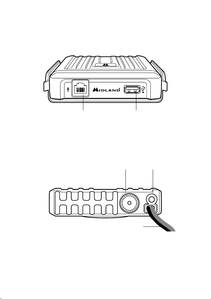
1. MIC - presa microfono: inserite lo spinotto del microfono nella presa.
2. Presa USB: fornisce una fonte di alimentazione (Max 2A - 5V) per ricaricare
in qualsiasi momento i vostri dispositivi
Pannello posteriore
35
EXT SP
ANT
4
3. Presa speaker: presa altoparlante esterno (questo collegamento esclude l’al-
toparlante interno).
4. Power 12.6VCC: presa d’alimentazione.
5. Connettore antenna: è previsto il connettore SO239.
M-5 Manuale d’uso | 3
Page 6
Microfono
1
3
5
9
+30
SIG
RFG
EMG
F
SCAN
A/F
SQ
88
8
RX TX EMG SC LOW
FM AM LOCK
ASQ
1
3
5
9
+30
SIG
RFG
EMG
F
SCAN
A/F
SQ
88
8
RX TX EMG SC LOW
FM AM LOCK
ASQ
16 17 18
6
15
7
8
9
11
12
13
14
10
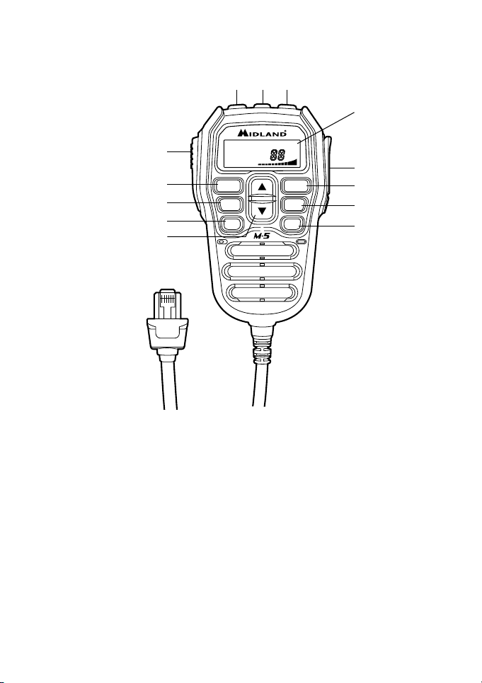
6. Display LCD
7. Presa MIC/SPK Kenwood: Presa per il collegamento ad un accessorio ester-
8. RFG: premere per attivare la modalità RF GAIN
9. EMG: tasto canale d’emergenza 9/19. Premere una volta per selezionare il
10. UP/DOWN: Tasti selezione canale. Premere UP o DOWN a seconda del ca-
11. Tasto F: tasto funzione e multifunzione (Funzione MUTE). Premere breve-
no.
canale 9; premere di nuovo per sintonizzarsi sul canale d’emergenza 19.
nale che si desidera.
mente due volte per bloccare/sbloccare la tastiera. Premere F + DOWN per
abilitare / disabilitare l’altoparlante del microfono. Premere F + A/F per poter
selezionare la banda di frequenza desiderata; è possibile scorrere le varie bande
con i tasti UP/DOWN, potete scegliere tra: CE – EU – IN – DE – I2 – IO
– PL - UK. Successivamente confermare tramite il tasto PTT.
4 | M-5 Manuale d’uso
Page 7
12. SCAN: tasto scansione. Premere brevemente per attivare la funzione scan.
Se durante la scansione si premono i tasti UP/DOWN si cambia la direzione
della scansione.
13. A/F: permette la selezione del modo di emissione AM/FM. Nelle bande UK o
CE (solo in modalità FM) premendo A/F si attiva la funzione LCR (richiamo
ultimo canale utilizzato)
14. SQ: la pressione di questo tasto permette di selezionare i vari livelli di squelch
mentre con la pressione lunga si commuta il tipo di squelch (manuale o digitale)
15. PTT: premere per trasmettere
16. SQ- / VOL: premere per ridurre il volume ed il livello di squelch. Lo squelch si
regola premendo il tasto SQ e di seguito UP/DOWN.
17. MUTE/PWR: la doppia pressione breve permette di disabilitare/abilitare l’altoparlante (funzione MUTE); la pressione lunga invece accende o spegne
l’apparato.
18. SQ+/VOL: premere per aumentare il volume ed il livello di squelch. Per regolare lo squelch, vedi punto 16 (SQ-/VOL).
Display
h
e
d g
c
RX TX EMG SC LOW
a
88
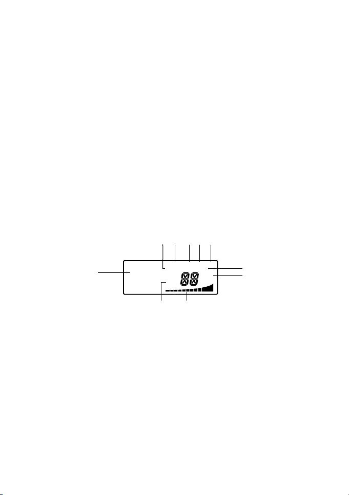
a. Numero canale selezionato
b. Indicatore S-METER di intensità del segnale ricevuto e di potenza del segnale
trasmesso
c. AM/FM: indicatore del modo di emissione
d. RX/TX: indicatore ricezione (RX) e trasmissione (TX)
e. SC: indicatore funzione SCAN attivata
f. ASQ: indicatore attivazione automatic squelch
g. LOW: indicatore bassa potenza
h. EMG: indicatore canale emergenza 9/19
i. LOCK: indicatore blocco tastiera attivo
j. Indicatore banda di utilizzo/MUTE/MENU
M-5 Manuale d’uso | 5
FM AM LOCK
ASQ
8
9
5
3
1
b
j
SIG
+30
i
f
Page 8

Installazione
Selezionare il luogo di installazione in modo che il dispositivo non pregiudichi la sicurezza e non metta a rischio l’incolumità in caso di incidente.
Grazie al cavo di alimentazione a 12V, M-5 non deve essere necessariamente montato ed installato nel veicolo come i classici CB, ma si può posizionare facilmente
ovunque sul vostro mezzo, anche nascosto non avendo tasti funzione sul corpo radio.
Alimentazione
Collegare il cavo accendisigari alla presa della vostra vettura. Assicuratevi che il vostro mezzo fornisca un’alimentazione a 12V e non a 24V.
Collegamento dell’antenna
Collegare l’antenna CB alla presa ANT sul retro dell’M-5. L’antenna deve essere
sintonizzata sulla banda radio CB (27 MHz). Per controllare il regolare funzionamento dell’impianto di antenna utilizzare un misuratore SWR.
Per un buon funzionamento dell’impianto radio e per ottenere le massime prestazioni dal dispositivo il valore dell’ SWR deve essere il più basso possibile e non superare un valore di 2. Un SWR alto è indice di qualche difetto dell’impianto di antenna
(controllare la linea di trasmissione, accertarsi che non vi siano interruzioni o corti
nel cavo coassiale dell’’antenna). Non trasmettere mai senza un’antenna connessa!
Nota: L’antenna radio deve essere montata il più lontano possibile da altre antenne,
oggetti metallici e fonti di interferenze. Di solito le antenne CB devono essere installate nella parte più alta del veicolo e su superfici metalliche. Una superficie metallica
sucientemente grande è essenziale per il buon funzionamento dell’antenna. In caso
di installazioni su veicoli privi di una superficie metallica (fibra di vetro o deflettori in
plastica), è possibile utilizzare speciali antenne che non richiedono la presenza del piano
metallico di massa.
6 | M-5 Manuale d’uso
Page 9

Funzionamento
Accensione/spegnimento della radio
Tenere premuto per 1 secondo il pulsante MUTE/POWER per accendere o spegnere M-5.
Al momento dell’accensione il display mostrerà per un secondo la banda di lavoro
operativa.
Controllo volume
Premere i pulsanti SQ/VOL+ o SQ/VOL- per regolare il volume; sono disponibili
10 livelli: da 0 a 9 (massimo livello).
Selezione del canale
Premere ripetutamente i tasti UP o DOWN sul frontale del microfono per selezionare il canale desiderato. Tenere premuti i tasti UP/DOWN sul microfono per
selezionare rapidamente il canale desiderato.
Controllo livello squelch (28 livelli e spento)
Premere brevemente il tasto SQ, il display mostrerà l’indicazione SQ ed il livello
corrente di squelch.
01 Squelch spento
02 Livello squelch più basso
28 Livello squelch più alto
Per variare il livello di squelch premere brevemente i tasti SQ- o SQ+ sul microfono
e selezionare il livello desiderato.
Nota: un livello di squelch alto richiede un segnale più forte per aprire l’audio dell’altoparlante ed ascoltare l’interlocutore.
Selezione squelch automatico (5 livelli) “DS” (Digital Squelch)
Tenere premuto SQ fino a quando viene visualizzata l’indicazione ASQ nella parte
destra del display.
01 Livello ASQ più basso
05 Livello ASQ massimo
Quando il display mostra ASQ è possibile modificare il livello premendo brevemente
il tasto SQ e successivamente cambiare il livello tramite i SQ- o SQ+.
Nota: un livello di ASQ alto richiede un segnale più forte per aprire l’audio in altoparlante
ed ascoltare l’interlocutore.
Tipo di modulazione
Premere brevemente il tasto A/F per commutare tra le modalità AM o FM.
M-5 Manuale d’uso | 7
Page 10

Il display LCD visualizzerà la modalità selezionata.
Nelle bande che comprendono una sola modulazione (FM) la pressione del tasto
A/F richiama l’ultimo canale utilizzato.
Controllo guadagno RF in ricezione
Premere brevemente il tasto RFG, il display mostra l’indicazione ‘R’ e per 5 secondi
il livello dell’RF gain attuale lampeggiante.
Quando il display mostra il livello attuale dell’RF gain lampeggiante è possibile modificarlo (aumentare o diminuire il livello di attenuazione in ricezione) premendo
brevemente i tasti UP o DOWN sul microfono.
I livelli di attenuazione selezionabili sono: da 06 (minima attenuazione) a 54 (massima attenuazione).
Quando la funzione RF è attiva, la vostra radio avrà la ricezione attenuata ed i segnali
di livello basso potrebbero non essere ricevuti.
Esempio: se il livello di RFG è settato a 24 significa che la radio riceve il segnale attenuato di 24 dB
Canale di emergenza
Premere brevemente il tasto EMG per selezionare il canale di emergenza CH9 (il
display mostra EMG lampeggiante).
Premere nuovamente il tasto EMG per selezionare il canale di emergenza CH19 (il
display mostra EMG lampeggiante).
Premere brevemente per una terza volta il tasto EMG per ritornare all’ultimo canale
in uso.
Blocco tasti
Premere rapidamente due volte il tasto F; il display visualizza “LOCK” ad indicare il
blocco tasti attivato.
Per sbloccare la tastiera del microfono, eseguire la stessa procedura.
Nota: in questa modalità, tutti i tasti sono disabilitati ad eccezione del PTT.
Funzione scansione
Premere il pulsante SCAN per avviare la scansione dei canali, il display mostrerà
l’indicazione “SC”.
Premere i tasti UP/DOWN sul microfono per modificare la direzione di scansione.
Premere di nuovo SCAN per arrestare ed uscire dalla scansione.
Modifica dello standard CB
Premere il tasto F e successivamente A/F.
Il display visualizza la banda di frequenza in uso (fare riferimento alla tabella seguente); premere i tasti UP o DOWN del microfono per scegliere la banda di frequenza
8 | M-5 Manuale d’uso
Page 11

desiderata.
Confermate con il tasto PTT. Il Led lampeggerà 3 volte di rosso ad indicare la nuova
banda selezionata.
Tabella bande di frequenza
Sigla sul display Paese
I0 Italia 40 CH AM/FM 4 Watt
I2 Italia 34 CH AM/FM 4 Watt
de Germania 80 CH FM 4 Watt / 40 CH AM 4 Watt
In Internazionale 27 CH AM/FM 4 Watt
EU Europa 40 CH FM 4 Watt / 40 CH AM 1 Watt
CE CEPT 40 CH FM 4 Watt
UK Inghilterra 40 CH FM 4 Watt frequenze inglesi
PL Polonia 40 CH AM/FM 4 Watt
ATTENZIONE! Lo standard sicuramente riconosciuto in tutti i paesi europei è 40CH
FM 4W (CE) - vedi tabella “Restrizioni all’uso”.
+ EC 40 CH FM 4 Watt frequenze CEPT
Altoparlante esterno
E’ possibile collegare un altoparlante esterno (8 Ohm) alla presa mono da 3,5 mm
sul retro della radio. L’altoparlante interno della radio viene automaticamente escluso quando viene inserito lo spinotto dell’altoparlante esterno.
Altoparlante microfono
È possibile disabilitare l’altoparlante del microfono nel seguente modo:
Premere F e successivamente DOWN
Il display mostrerà SP OFF.
Abilitare l’altoparlante premendo F e di seguito DOWN; il display visualizzerà SP
ON.
Ripristino impostazioni di fabbrica (RESET)
Premere in sequenza: FUPEMG
Dopo questa operazione tutte le impostazioni della radio saranno ripristinate alle
impostazioni di fabbrica. Dopo il reset la radio sarà operativa in FM sul canale 9
della banda CE.
M-5 Manuale d’uso | 9
Page 12

Specifiche tecniche
Gamma di frequenza* 26.565-27.99125 MHz
Dimensioni 110 x 120 x 25 mm
Peso 380 gr
Tensione di alimentazione 12.6V ± 10%
Consumo 2 A max
Gamma di temperatura d’uso da -10 a +55 °C
Presa per l’antenna UHF, SO-239
Errore di frequenza < +/- 300 Hz
Potenza TX 4 Watt
Ciclo di utilizzo (% su 1 ora) TX 5% / RX 5% / Stand-by 90%
Emissioni spurie < 4 nW (-54 dBm)
Potenza canali adiacenti < 20 μW
Deviazione FM 1,9 kHz
Indice di modulazione AM 85-90%
Sensibilità RX migliore di 1 μV
Scarto immagine 70 dB
Scarto canale adiacente 60 dB
Doppia uscita audio 3 Watt (8 Ohm) corpo radio;
2 Watt (16 Ohm) microfono
Risposta in frequenza 300-3000 Hz
* considerando tutte le bande di frequenza europee approvate.
Le specifiche sono soggette a modifiche senza preavviso.
Un dispositivo di sezionamento adatto deve essere previsto nell’impianto elettrico. Tale dispositivo deve disconnettere entrambi i poli simultaneamente
10 | M-5 Manuale d’uso
Page 13

Index
Main features 2
What’s in the box 2
Controls description 3
Installation 6
Power supply 6
Installing an antenna 6
Operation 7
Technical specifications 10
M-5 Instruction Guide | 1
Page 14

M-5 represents the state-of-the-art in technology and is the big news in the CB
world: all controls are placed on the microphone to make the use much easier and
to always have the CB “in your hands”.
M-5 is in compliance with the latest European CB regulations and is equipped with
the main European frequency bands to be used in all EU countries.
Main features
• Black box multistandard radio with multifunction microphone
• Microphone buttons with backlight (on/o)
• UP/DOWN controls
• Channel scan
• LCD display with S/Meter in tx/rx
• Display backlight adjustable in 7 dierent colors
• Squelch adjustable in 28 levels
• Digital Squelch selectable in 5 dierent levels
• Selectable dual speaker (radio and microphone)
• USB port on the front panel to recharge electronic devices, max 2A
• RF gain adjustable in AM and FM
• Emergency channel 9/19
• Volume selectable in 10 dierent levels
• “MUTE” function
• Keypad Beep on/o
• Keypad lock
• Ext speaker jack
• 2pin Kenwood plug on the microphone
What’s in the box
• M-5 transceiver with multi-function microphone
• Mounting bracket and fixing screws
• Power cord with cigarette lighter socket
2 | M-5 Instruction Guide
Page 15
Controls description
RFG
88
RFG
EMG
F
88
Radio
21
1. MIC – microphone socket: plug the mike connector into this jack.
2. USB port: this socket is a power supply source (Max 2A - 5V) to recharge
your electronic devices whenever you want.
Rear panel
35
EXT SP
ANT
4
3. EXT SP jack: external speaker jack (if you connect an external speaker, the
built-in speaker will be excluded).
4. Power 12.6VDC: power supply cable
5. Antenna connector: SO239 type.
M-5 Instruction Guide | 3
Page 16

Microphone
1
3
5
9
+30
SIG
RFG
EMG
F
SCAN
A/F
SQ
88
8
RX TX EMG SC LOW
FM AM LOCK
ASQ
1
3
5
9
+30
SIG
RFG
EMG
F
SCAN
A/F
SQ
88
8
RX TX EMG SC LOW
FM AM LOCK
ASQ
16 17 18
6
15
7
8
9
11
12
13
14
10
6. LCD display
7. MIC/SPK Kenwood jack: socket for the connection to an external accessory,
8. RFG: press to activate RF GAIN
9. EMG: button suitable for the emergency channels (9/19) activation. Press
10. UP/DOWN: Push UP or DOWN to select the desired channel.
11. F button: function and multi-function control. Shortly press twice to lock/
such as headsets, earphone/mikes, etc.
once to select channel 9, push it again for the immediate selection of channel
19.
unlock the keypad. Press F + DOWN to activate / deactivate the speaker of
the microphone. Press F + A/F to select the desired frequency band; with the
UP/DOWN buttons you can select the desired band; choose amongst the
following ones available: CE – EU – IN – DE – I2 – I0 – PL - UK. Then push
PTT for confirmation.
4 | M-5 Instruction Guide
Page 17

12. SCAN: scan button. Shortly press to activate the scan function. While scanning you can change the direction by pushing UP or DOWN.
13. A/F: to select the AM or FM mode. If you select UK or CE bands (operating
in FM mode only) by pressing this button you enable the LCR function (Last
Channel Recall)
14. SQ: short press to select the squelch levels, while if you keep this button pressed you can change the type of squelch (manual or digital)
15. PTT: press to transmit
16. SQ- / VOL: push to reduce the volume and the squelch level. The squelch can
be adjusted by pressing SQ and then UP/DOWN.
17. MUTE/PWR: push twice to enable/disable the speaker (MUTE function); if
you keep it pressed you turn on/o the transceiver.
18. SQ+/VOL: push to increase the volume and the squelch level. To adjust the
squelch, see point 16 (SQ-/VOL).
Display
h
e
d g
c
RX TX EMG SC LOW
a
88
a. Selected channel number
b. S-METER. Received signal strength indicator and transmission power signal
c. AM/FM mode
d. RX/TX indicator: reception (RX) and transmission (TX)
e. SC: SCAN function activated
f. ASQ: automatic squelch activated
g. LOW: low power indicator
h. EMG: emergency channel 9/19 indicator
i. LOCK: keypad lock activated
j. Operating band / MUTE / MENU indicator
M-5 Instruction Guide | 5
FM AM LOCK
ASQ
8
9
5
3
1
b
j
SIG
+30
i
f
Page 18

Installation
Find the proper position to install the device without interfering with safety while
operating with your vehicle.
Thanks to the 12V socket, the installation of the radio is extremely quick and immediate; it can only be placed in small places, also not in sight, having all operating
keys on the microphone.
Power supply
Connect the cigarette lighter power cable to the proper plug of your vehicle. Be
sure your car has a power supply of 12V and not 24V.
Installing an antenna
Connect the CB antenna to the ANT socket on the back of M-5. The antenna must
be tuned to the CB radio band (27 MHz). To verify the proper functioning of the
antenna, use a SWR meter.
For a good radio range, the SWR should not exceed a value of 2. A high SWR value
points out a defect in the antenna system, cable or a shourt circuit in the antenna
line. Never transmit without a connected antenna!
Note: The radio antenna is to be mounted as far as possible from other antennas, metallic objects and interferences sources. CB antennas must be usually mounted in the vehicle highest part on a metal surface. A suciently large metallic surface is essential for
the proper functioning of the antenna. For installation on fiberglass cabs or plastic wind
defectors, it is possible to use special antennas that do not require a metallic ground.
6 | M-5 Instruction Guide
Page 19

Operation
Power on/o
Keep pressed for 1 second the MUTE/POWER button to turn on/o M-5.
The display will show for 1 second the opearating band.
Volume control
Press SQ/VOL+ o SQ/VOL- to adjust the volume; you can choose amongst 10
levels: from 0 to 9 (max level).
Channel selection
Press the UP/DOWN controls on the mike to scroll through the channels and select the desired one.
Keep pressed UP/DOWN for a quick scroll of the channels.
Squelch level control (28 levels)
Shortly press SQ, the display will show SQ and the current squelch level.
01 Squelch o
02 Lowest squelch level
28 Highest squelch level
To change the squelch level shortly press SQ- or SQ+ on the mike and select the
desired level.
Note: a high squelch level requires a stronger signal to open the speaker audio and to
listen to the other part.
“DS” Digital Squelch selection (5 levels)
Hold down the SQ control till ASQ appears on the right side of the display.
01 Lowest ASQ level
05 Max ASQ level
When ASQ is displayed, it is possible to change the level by pressing SQ and then
using SQ- or SQ+.
Note: a high ASQ level requires a stronger signal to open the speaker audio and to listen
to the other part.
AM/FM
Shortly press A/F to switch between AM or FM mode.
The LCD will show the selected mode.
If you operate in operating bands with FM modulation only, the pressure of the A/F
key recalls the latest channel in use.
M-5 Instruction Guide | 7
Page 20

RF gain control
Shortly press the RFG key, the display shows ‘R’ and the current RF gain level blinks.
When the RF gain level flashes it is possible to change it (increase or decrease) by
shortly pressing the UP or DOWN keys on the microphone.
The attenuation levels that can be selected are from 06 (minimum) to 54 (max
attenuation).
When the RFG feature is on, M-5 will receive attenuatly and the lowest signals
could not be received.
Example: if the RFG level is set to 24, the attenuation will be 24dB.
Emergency channel
Shortly press EMG to select the emergency channel CH9 (EMG will blink on the
display).
Press EMG again to select the emergency channel CH19 (EMG will blink on the
display).
Push the button for the third time to return to the latest channel in use.
Keypad lock
Shortly press twice the F key; the display will show “LOCK” .
Follow the same procedure to unlock the keypad of the microphone.
Note: when the lock is enabled, only PTT can be used.
Scan function
Push the SCAN key to start scanning; “SC” will appear on the display.
Press UP/DOWN on the microphone to change the scan direction. To stop and
exit the scan , press SCAN again.
Frequency band selection
Press the F control and then A/F.
The LCD shows the frequency band currently in use (see the following chart); you
can choose the desired band with the UP or DOWN keys on the microphone.
Then confirm your selection with PTT. The Led on the mike will blink red for 3 times
to indicate the new band just selected.
8 | M-5 Instruction Guide
Page 21

Frequency band chart
Digits displayed Country
I0 Italy 40 CH AM/FM 4 Watt
I2 Italy 34 CH AM/FM 4 Watt
de Germany 80 CH FM 4 Watt / 40 CH AM 4 Watt
In International 27 CH AM/FM 4 Watt
EU Europe 40 CH FM 4 Watt / 40 CH AM 1 Watt
CE CEPT 40 CH FM 4 Watt
UK England 40 CH FM 4 Watt English frequencies + EC 40 CH
PL Poland 40 CH AM/FM 4 Watt
Note: The frequency band allowed all over Europe is 40 CH FM 4W (CE). See the
“Restrictions on the use” chart.
FM 4 Watt CEPT frequencies
External speaker
An external speaker (8 Ohm) can be connected to the 3.5mm mono socket on
the back of the radio. The built-in speaker automatically turns o when a plug is
inserted into this jack.
Microphone speaker
It is possible to disable the microphone speaker with the following procedure:
Press F and then DOWN
The LCD will show SP OFF.
To enable the speaker again, press F followed by DOWN; SP ON will appear on
the display.
Restore to factory defaults (RESET)
Press : F UPEMG
After this procedure all settings will return to factory defaults. The radio will be tuned on CH9 of the CE band (FM).
M-5 Instruction Guide | 9
Page 22

Technical specifications
Frequency band* 26.565-27.99125 MHz
Dimensions 110 x 120 x 25 mm
Weight 380gr
Supply voltage 12.6V ± 10%
Current consumption 2 A max
Operating temperature -10 to +55 °C
Antenna socket UHF, SO-239
Frequency error < +/- 300 Hz
TX power 4 Watt
Duty cycle (% on 1 hour) TX 5% / RX 5% / Stand-by 90%
Spurious emissions < 4 nW (-54 dBm)
Adjacent channel power < 20 μW
FM deviation 1,9 kHz
AM modulation index 85-90%
RX sensitivity better than 1 μV
Image rejection 70 dB
Adjacent channel rejection 60 dB
Dual audio output 3 Watt (8 Ohm) radio body; 2 Watt (16 Ohm) microphone
Frequency response 300-3000 Hz
*covering all approved EU frequency bands.
Specifications are subject to change without notice.
A redily accessibile disconnect device shell be incorporated in the installation wiring. The disconnect device shall disconnect both poles simultaneously.
10 | M-5 Instruction Guide
Page 23

Inhalt
Haupteigenschaften 2
Lieferumfang 2
Beschreibung der Bedienelemente 3
Installation 6
Stromversorgung 6
Installation der Antenne 6
Bedienungshinweise 7
Technische Daten 10
M-5 Bedienungsanleitung | 1
Page 24

M-5 steht für moderne Technologie und ist die neue Bedienerfreundlichkeit in der
CB-Welt: alle Bedienelemente befinden sich auf dem Mikrofon, um den Einsatz viel
einfacher zu machen und das CB immer „in Ihren Händen“ zu behalten.
M-5 entspricht den neuesten europäischen CB-Vorschriften und ist mit den
wichtigsten europäischen Frequenzbändern ausgestattet, um in allen EU-Ländern
eingesetzt zu werden.
Haupteigenschaften
• Black Box Multistandard-CB-Radio mit Multifunktions-Mikrofon
• Mikrofontasten mit abschaltbarer Hintergrundbeleuchtung (ein/aus)
• AUF/AB-Bedientasten
• Kanal-Scan Funktion
• LCD-Anzeige für Empfangs und Sendeanzeige
• Display-Hintergrundbeleuchtung in 7 verschiedenen Farben einstellbar
• Rauschsperrepegel in 28 Stufen einstellbar
• Digitale Rauschsperre in 5 verschiedenen Stufen wählbar
• Geräte und Mikrofon Lautsprecher schaltbar
• USB-Anschluss an der Vorderseite zum Aufladen von elektronischen Geräten,
max 2 A
• Empfangsverstärkung in AM und FM einstellbar
• Notfallkanal 9/19
• Lautstärke in 10 verschiedenen Stufen wählbar
• „MUTE“-Funktion
• Mikrofon-Tastatur Signalton an/aus
• Mikrofon-Tastatursperre
• Externe Lautsprecherbuchse
• 2-polige Anschlussbuchse für Kenwood-Zubehör am Mikrofon
Lieferumfang
• M-5- CB-Funkgerät mit Multifunktions-Mikrofon
• Halterung und Befestigungsschrauben
• Netzkabel mit Zigarettenanzünderstecker
2 |
M-5 Bedienungsanleitung
Page 25

Beschreibung der Bedienelemente
RFG
88
RFG
EMG
F
88
Vorderseite
21
1. MIK - Mikrofonbuchse: Schließen Sie den Mikrofonstecker an dieser Buchse an.
2. USB-Anschluss: Buchse (Max. 2 A - 5 V) für das Aufladen Ihrer
elektronischen Geräte (z.B. Smartphones).
Rückseite
35
EXT SP
ANT
4
3. EXT SP-Buchse: Externe Lautsprecher-Buchse (wenn Sie einen externen
Lautsprecher anschließen, wird der eingebaute Lautsprecher abgeschaltet).
4. Strom 12,6 V DC: Stromversorgungskabel
5. Antennenanschluss: Typ SO239.
M-5 Bedienungsanleitung | 3
Page 26

Mikrofon
1
3
5
9
+30
SIG
RFG
EMG
F
SCAN
A/F
SQ
88
8
RX TX EMG SC LOW
FM AM LOCK
ASQ
1
3
5
9
+30
SIG
RFG
EMG
F
SCAN
A/F
SQ
88
8
RX TX EMG SC LOW
FM AM LOCK
ASQ
16 17 18
6
15
7
8
9
11
12
13
14
10
6. LCD-Display
7. MIK/LAUTSPR. Kennwood-Buchse: Buchse für den Anschluss von externem
8. RFG: Drücken, um Empfangsverstärkung (RF Gain) zu aktivieren
9. EMG: Taste für die Aktivierung von Notfallkanälen (9/19). Drücken Sie diese
10. UP/DOWN: Drücken Sie UP oder DOWN zur Auswahl des gewünschten
11. F-Taste: Funktion- und Multifunktions-Kontrolle. Zweimal kurz drücken, um
Zubehör wie Headsets, Kopörer, Mikrofone, usw.
Taste einmal, um den Kanal 9 auszuwählen; Ein erneutes Drücken führt zur
sofortigen Auswahl von Kanal 19.
Funk-Kanals.
die Tastatur zu sperren/entsperren. Drücken Sie F + DOWN zum Aktivieren/
Deaktivieren des Mikrofonlautsprechers. Drücken Sie F + A/F zur Auswahl der
gewünschten Betriebsart (AM/FM); mit den Tasten UP/DOWN können Sie
den gewünschten Ländercode wählen: Wählen Sie unter folgenden verfügbaren
Ländern:
CE – EU – IN – DE – I2 – I0 – PL - UK. Drücken Sie dann PTT zur
Bestätigung.
4 |
M-5 Bedienungsanleitung
Page 27

12. SCAN (Suchlauf-Taste): Ein kurzer Druck aktiviert die Suchfunktion.
Während des Suchlaufs können Sie die Suchrichtung ändern, indem Sie UP
oder DOWN drücken.
13. A/F: zur Auswahl des AM- oder FM-Modus. Wenn Sie UK- oder CE-Bänder
(nur im FM-Modus) durch Drücken dieser Taste wählen, aktivieren Sie die
LCR-Funktion (Letzten Kanal wieder aufrufen)
14. SQ: Kurz drücken, um den Rauschsperrepegel auszuwählen; Wenn Sie diese
Taste gedrückt halten, können Sie die Art der Rauschsperre (manuell oder
digital) wechseln.
15. PTT: Drücken, um zu senden
16. SQ-/VOL: Drücken, um die Lautstärke und den Rauschsperrepegel zu
reduzieren. Die Rauschsperre kann durch Drücken von SQ und dann UP/
DOWN eingestellt werden.
17. MUTE/PWR: Zweimal drücken, um den Lautsprecher zu aktivieren/
deaktivieren (MUTE-Funktion); Wenn Sie die Taste gedrückt halten, schalten
Sie den Sender-Empfänger ein/aus.
18. SQ+/VOL: Drücken, um die Lautstärke und den Rauschsperrepegel zu
erhöhen. Zur Einstellung der Rauschsperre siehe Punkt 16 (SQ-/VOL).
Anzeige
h
e
d g
c
RX TX EMG SC LOW
a
88
a. Anzeige des aktuellen Kanals
b. S-METER. Anzeige der empfangenen Signalstärke und Stärke des Sende-
Signal
c. AM/FM-Modus
d. RX/TX-Indikator: Empfang (RX) und Senden (TX)
e. SC: Such-Funktion aktiviert
f. ASQ: Automatische Rauschsperre aktiviert
g. LOW: Anzeige geringer Sendeleistung
h. EMG: Anzeige für Notfallkanal 9/19
i. LOCK: Tastensperre ist aktiviert
j. Anzeige für Betriebsband/MUTE/MENU
M-5 Bedienungsanleitung | 5
FM AM LOCK
ASQ
8
5
3
1
b
j
SIG
+30
9
i
f
Page 28

Installation
Suchen Sie den richtigen Montageort für die Installation des Gerätes, ohne die
Sicherheit zu beeinträchtigen, während Sie Ihr Fahrzeug betreiben.
Dank des 12V-Zigararettenanzünder-Steckers ist die Installation des Radios schnell
und einfach. Das M-5 benötigt nicht viel Platz und kann auch außer Sichtweite
eingebaut werden, da sich alle Bedienelemente am Mikrofon befinden.
Stromversorgung
Verbinden Sie den Zigarettenanzünder-Stecker mit dem 12 Volt Zigarattenanzünder
im Fahrzeug. Vergewissern Sie sicher, dass Ihr Auto eine Stromversorgung von 12V
und nicht 24V hat.
Installation der Antenne
Schließen Sie die CB-Antenne an der Buchse ANT auf der Rückseite Ihres M-5
an. Die Antenne muss auf das CB-Funkband abgestimmt sein (27 MHz). Um
die ordnungsgemäße Funktion der Antenne zu überprüfen, verwenden Sie ein
Stehwellen-Messgerät (SWR).
Für eine gute Funkreichweite sollte das Stehwellenverhältnis den Wert 2 nicht
übersteigen. Ein hoher Wert des Stehwellenverhältnis weist auf einen Defekt im
Antennensystem, Kabel oder einen Kurzschluss in der Antennenleitung hin. Funken
Sie keinesfalls ohne angeschlossene Antenne!
Hinweis: Die Funkantenne sollte so weit wie möglich von anderen Antennen, metallischen
Objekten und Interferenzquellen montiert werden. CB-Antennen sollten in der Regel am
höchsten Teil des Fahrzeugs und müssen auf einer Metalloberfläche montiert werden.
Für die ordnungsgemäße Funktion der Antenne ist eine ausreichend große metallische
Oberfläche unerlässlich. Für die Montage auf Glasfaserkabinen oder KunststoWindabweisern ist es möglich, spezielle Antennen zu verwenden, die keinen metallischen
Boden benötigen.
6 |
M-5 Bedienungsanleitung
Page 29

Bedienungshinweise
Ein/Aus
Halten Sie die MUTE/POWER-Taste für 1 Sekunde gedrückt, um das M-5 einoder auszuschalten.
Das Display zeigt für 1 Sekunde den Ländercode an.
Lautstärkeregler
Drücken Sie SQ/VOL+ oder SQ/VOL- , um die Lautstärke anzupassen. Sie können
zwischen 10 Stufen wählen: von 0 to 9 (max. Stufe).
Kanalwahl
Drücken Sie die Tasten UP/DOWN am Mikrofon, um durch die Kanäle zu blättern
und den gewünschten Kanal auszuwählen.
Für ein schnelles Durchblättern der Kanäle halten Sie die Taste UP/DOWN gedrückt.
Rauschsperrenpegel-Einstellung (28 Stufen)
Drücken Sie kurz SQ, um auf dem Display SQ und den gegenwärtigen
Rauschsperrenpegel angezeigt zu bekommen.
01 Rauschsperre aus
02 Niedrigster Rauschsperrepegel
28 Höchster Rauschsperrepegel
Um den Rauschsperrepegel zu ändern, drücken Sie kurz SQ- oder SQ+ am
Mikrofon und wählen Sie den gewünschten Pegel aus.
Hinweis: Ein höherer Rauschsperrepegel erfordert ein stärkeres Empfangssignal, um die
Lautsprecher-Wiedergabe zu önen und den Gesprächspartner zu hören.
„DS“ Digitale Rauschsperrenauswahl (9 Stufen)
Halten Sie die SQ-Taste gedrückt, bis ASQ .auf der rechten Seite des Displays
angezeigt wird.
01 Niedrigster ASQ-Pegel
05 Höchster ASQ-Pegel
Wenn ASQ angezeigt wird, ist es möglich, den Pegel durch drücken von SQ und
nachfolgender Betätigung der Tasten SQ- oder SQ+ zu ändern.
Hinweis: Ein höherer ASQ-Pegel erfordert ein stärkeres Signal, um die LautsprecherWiedergabe zu önen und Gesprächspartner zu hören.
AM/FM
Drücken Sie kurz A/F, um zwischen dem AM- und FM-Modus zu wechseln.
Die LCD-Anzeige zeigt den ausgewählten Modus.
Wenn Sie in einem Ländercode auswählen, der nur FM-Modulation zulässt, wird
durch Drücken der Taste A/F der zuletzt verwendete Kanal aufgerufen.
M-5 Bedienungsanleitung | 7
Page 30

RF-Gain
Drücken Sie kurz die Taste RFG und das Display zeigt „R“ und der aktuelle
Empfangs-Verstärkungspegel blinkt.
Durch die Tasten UP oder DOWN am Mikrofon können Sie den EmpfangsVerstärkungspegel. erhöhen oder verringern.
Die Dämpfungspegel können von 06 (Minimum) bis 54 (max. Dämpfung)
ausgewählt werden.
Wenn die RFG-Funktion aktiviert ist, wird der Empfang des M-5 gedämpft und die
schwächsten Signale können nicht mehr empfangen werden.
Beispiel: Wenn der HF-Verstärkungspegel auf 24 eingestellt ist, ist die Dämpfung 24 dB.
Notruanal
Drücken Sie kurz EMG zur Auswahl des Notruanals CH9 (EMG blinkt auf dem
Display).
Drücken Sie EMG erneut zur Auswahl des Notruanals CH19 (EMG blinkt auf
dem Display).
Drücken Sie die Taste ein drittes Mal, um zu dem zuletzt verwendeten Kanal
zurückzukehren.
Tastatursperre
Drücken Sie zweimal die Taste F kurz und auf dem Display wird „LOCK“ angezeigt.
Führen Sie diesen Schritt ebenfalls aus, um die Tastatur des Mikrofons wieder zu
entsperren.
Hinweis: Wenn die Sperre aktiviert ist, kann nur PTT verwendet werden.
Scan-Funktion
Drücken Sie die Taste SCAN, um den Scanvorgang zu starten; auf dem Display
wird „SC“ angezeigt.
Drücken Sie an dem Mikrofon UP/DOWN, um die Suchrichtung zu ändern. Um
den Vorgang anzuhalten und zu verlassen, drücken Sie erneut die Taste SCAN.
Auswahl des Ländercodes
Drücken Sie die Taste F und anschließend die Taste A/F.
Die LCD-Anzeige zeigt den aktuell verwendete Ländercode an (siehe nachfolgende
Tabelle); Sie können den gewünschte Ländercode mit den Tasten UP oder DOWN
am Mikrofon auswählen.
Bestätigen Sie Ihre Auswahl anschließend mit der Taste PTT. Die LED am Mikrofon
blinkt 3 Mal rot, um anzuzeigen, dass ein neues Band ausgewählt wurde.
8 |
M-5 Bedienungsanleitung
Page 31

Frequenzband-Tabelle
Angezeigte
Ziern
I0 Italien 40 CH AM/FM 4 Watt
I2 Italien 34 CH AM/FM 4 Watt
de Deutschland 80 CH FM 4 Watt/40 CH AM 4 Watt
In International 27 CH AM/FM 4 Watt
EU Europa 40 CH FM 4 Watt/40 CH AM 1 Watt
CE CEPT 40 CH FM 4 Watt
UK England 40 CH FM 4 Watt Englische Frequenzen
+ EC 40 CH FM 4 Watt CEPT-Frequenzen
PL Polen 40 CH AM/FM 4 Watt
Hinweis: Der in ganz Europa erlaubte Ländercode ist 40 CH FM 4W (CE). Siehe
Tabelle „Beschränkungen für die Verwendung“.
Land
Externer Lautsprecher
Ein externer Lautsprecher (8 Ohm) kann an der 3,5mm Mono-Buchse auf der
Rückseite des Funkgeräts angeschlossen werden. Der eingebaute Lautsprecher
schaltet sich automatisch aus, wenn an dieser Buchse ein Anschluss vorgenommen
wird.
Mikrofon-Lautsprecher
Der Lautsprecher am Mikrofon kann wie folgt abgeschaltet werden:
Drücken Sie F und anschließend DOWN
Die LCD-Anzeige zeigt SP OFF.
Um den Lautsprecher wieder einzuschalten, drücken Sie F gefolgt von DOWN; SP
ON wird auf dem Display angezeigt.
Wiederherstellen der Werkseinstellungen (RESET)
Drücken Sie: F UPEMG
Durch diese Funktion werden alle Einstellungen wieder auf die Werkseinstellungen
zurückgesetzt. Das M-5 wird auf Kanal 9 des CE-Bandes (FM) eingestellt.
M-5 Bedienungsanleitung | 9
Page 32

Technische Daten
Frequenzbereich* 26,565-27,99125 MHz
Abmessungen 110 x 120 x 25 mm
Gewicht 380 g
Versorgungsspannung 12,6V ± 10%
Stromaufnahme max. 2 A
Umgebungs-Temparatur -10 bis +55 °C
Antennenbuchse UHF, SO-239
Frequenzfehler < +/- 300 Hz
Sendeleistung 4 Watt
Tastgrad (% auf 1 Stunde) TX 5 %/RX 5 %/Standby 90 %
Nebenwellen-Aussendungen < 4 nW (-54 dBm)
Nachbarkanalleistung < 20 μW
FM-Frequenzhub 1,9 KHz
AM modulation index 85-90%
Empfangsempfindlichkeit besser als 1 μV
Spiegelselektion 70 dB
Nachbarkanalunterdrückung 60 dB
Duale Audioausgabe 3 Watt (8 Ohm) Gerät
2 Watt (16 Ohm) Mikrofon-Anschluss
Frequenzgang 300-3000 Hz
*deckt alle zugelassenen EU-Frequenzbänder ab.
Änderungen der technischen Daten vorbehalten.
In die Installationsverkabelung muss eine leicht zugängliche Trennvorrichtung eingebaut werden.
Die Trennvorrichtung muss beide Pole gleichzeitig trennen.
10 |
M-5 Bedienungsanleitung
Page 33

Índice
Características principales 2
La caja incluye 2
Descripción de los controles 3
Instalación 6
Alimentación 6
Instalación de una antena 6
Funcionamiento 7
Especificaciones técnicas 10
M-5 Manual de Instrucciones | 1
Page 34

M-5 representa la tecnología de vanguardia y es una gran noticia en el mundo de la
CB: todos los controles se han colocado en el micrófono para hacer el uso mucho
más fácil y tener siempre la CB en sus manos.
M-5 cumple con las últimas regulaciones europeas de CB y está equipada con las
principales bandas de frecuencias europeas que se utilizarán en todos los países de
la UE.
Características principales
• Transceptor multiestándar black box con micrófono multifunción
• Teclas del micrófono retroiluminadas (on/o)
• Teclas ARRIBA/ABAJO
• Escáner de canales
• Display LCD con S/Meter en tx/rx
• Retroiluminación del display regulable en 7 colores
• Squelch regulable en 28 niveles
• Squelch digital seleccionable en 5 niveles distintos
• Doble altavoz (transceptor y micrófono) seleccionable
• Toma USB frontal para recarga máx. 2A
• Atenuador de recepción (ganancia de RF) regulable en AM y FM
• Canales de emergencia 9/19
• Volumen regulable en 10 niveles
• Función “MUTE”
• Sonido del teclado on/o
• Bloqueo del teclado
• Toma para altavoz externo
• Conector 2pin Kenwood en el micrófono
La caja incluye
• Transceptor M-5 con micrófono multifunción
• Soporte de montaje y tornillos de fijación
• Cable de alimentación con toma de encendedor
2 | M-5 Manual de Instrucciones
Page 35

Descripción de los controles
RFG
88
RFG
EMG
F
88
Radio
21
1. MIC – toma de micrófono: enchufe el conector del mic en esta toma.
2. Puerto USB: proporciona una fuente de energía (máx. 2A - 5V) para recargar
sus dispositivos en cualquier momento.
Panel trasero
35
EXT SP
ANT
4
3. Toma EXT SP: toma de altavoz externo (este conector excluye el altavoz in-
terno).
4. Power 12.6VCC: toma de alimentación.
5. Conector antena: conector SO239.
M-5 Manual de Instrucciones | 3
Page 36

Micrófono
1
3
5
9
+30
SIG
RFG
EMG
F
SCAN
A/F
SQ
88
8
RX TX EMG SC LOW
FM AM LOCK
ASQ
1
3
5
9
+30
SIG
RFG
EMG
F
SCAN
A/F
SQ
88
8
RX TX EMG SC LOW
FM AM LOCK
ASQ
16 17 18
6
15
7
8
9
11
12
13
14
10
6. Display LCD
7. Toma MIC/SPK Kenwood: toma para la conexión a un accesorio externo.
8. RFG: presione para activar el modo RF GAIN
9. EMG: botón canal de emergencia 9/19. Pulse una vez para seleccionar el canal
10. ARRIBA/ABAJO: teclas de selección de canal. Presione arriba o abajo para
11. Botón F: botón función y multifunción (Función MUTE). Pulse brevemente
12. SCAN: pulse brevemente para activar la función SCAN. Si durante el esca-
9; pulse de nuevo para sintonizar el canal de emergencia 19.
seleccionar el canal deseado.
dos veces para bloquear/desbloquear el teclado. Pulse F + ABAJO para activar / desactivar el altavoz del micrófono. Pulse F + A/F para poder seleccionar la banda de frecuencia deseada; puede desplazarse a través de las diversas
bandas con los botones ARRIBA/ABAJO, puede elegir entre: CE – EU – IN
– DE – I2 – I0 – PL - UK. A continuación, confirmar con la tecla PTT.
4 | M-5 Manual de Instrucciones
Page 37

neado se pulsa el botón ARRIBA / ABAJO, cambia la dirección de la exploración.
13. A/F: permite la selección del modo de emisión AM/FM. En las bandas UK
o CE (solo en FM), pulsando A/F se activa la función LCR (memoria último
canal utilizado).
14. SQ: la pulsación corta de este botón permite seleccionar varios niveles de
squelch, mientras que con la pulsación larga se cambia el tipo de squelch (digital o manual).
15. PTT: pulse para transmitir.
16. SQ- / VOL: pulse para reducir el volumen y el nivel de squelch. El squelch se
regula pulsando el botón SQ y después ARRIBA/ABAJO.
17. MUTE/PWR: la doble pulsación corta permite activar / desactivar el altavoz
(función MUTE); la pulsación larga enciende o apaga el aparato.
18. SQ+/VOL: pulse para aumentar el volumen y el nivel de squelch. Para ajustar
el squelch, véase el párrafo 16 (SQ / VOL).
Display
h
e
d g
c
RX TX EMG SC LOW
a
88
a. Número de canal seleccionado
b. Indicador S-METER de intensidad de la señal recibida y de potencia de la
señal transmitida
c. Modo AM/FM
d. RX/TX: indicador recepción (RX) y transmisión (TX)
e. SC: función SCAN activada
f. ASQ: activación squelch automático
g. LOW: indicador de baja potencia
h. EMG: indicador de canal de emergencia 9/19
i. LOCK: bloqueo del teclado activado
j. Indicador banda operativa / MUTE / MENU
M-5 Manual de Instrucciones | 5
FM AM LOCK
ASQ
8
9
5
3
1
b
j
SIG
+30
i
f
Page 38

Instalación
Encuentre la posición adecuada para instalar el dispositivo sin interferir con la seguridad mientras trabaja con su vehículo.
Gracias a la toma de 12V, la instalación de la radio es extremadamente rápida e
inmediata; se puede colocar en lugares pequeños o no a la vista, ya que tiene todas
las teclas de funcionamiento en el micrófono.
Alimentación
Conecte el cable de alimentación con toma de encendedor al enchufe adecuado
de su vehículo. Asegúrese de que su coche tiene una fuente de alimentación de
12V y no 24V.
Instalación de una antena
Conecte la antena CB a la toma ANT en la parte trasera de la M-5. La antena debe
ser sintonizada a la banda de radio CB (27 MHz). Para verificar el buen funcionamiento de la antena, utilice un medidor de SWR.
Para un buen rango de radio, el SWR no debe exceder un valor de 2. Un alto valor
de SWR señala un defecto en el sistema de antena, del cable o un cortocircuito en
la línea de antena. ¡Nunca transmita sin una antena conectada!
Nota: la antena de radio debe montarse lo más lejos posible de otras antenas, objetos
metálicos y fuentes de interferencias. Las antenas CB deben montarse generalmente
en la parte más alta del vehículo sobre una superficie metálica. Una superficie metálica
suficientemente grande es esencial para el buen funcionamiento de la antena. Para la
instalación en cabinas de fibra de vidrio o deflectores de viento de plástico, es posible
utilizar antenas especiales que no requieran una superficie metálica.
6 | M-5 Manual de Instrucciones
Page 39

Funcionamiento
Encendido/apagado
Mantenga presionado durante 1 segundo el botón MUTE/POWER para encender/
apagar la M-5.
La pantalla mostrará durante 1 segundo la banda operativa.
Volumen
Pulse SQ/VOL+ o SQ/VOL- para ajustar el volumen; puede escoger entre 10 niveles: de 0 a 9 (nivel máx).
Selección de canales
Pulse las teclas ARRIBA/ABAJO en el micrófono para navegar por los canales y
seleccionar el deseado.
Mantenga presionado ARRIBA/ABAJOpara un recorrido rápido por los canales.
Control del nivel del Squelch (28 niveles)
Pulse brevemente SQ, el display mostrará SQ y el nivel actual del squelch.
01 Squelch o
02 Mínimo nivel squelch
28 Máximo nivel squelch
Para cambiar el nivel de squelch pulse brevemente SQ- o SQ+ en el micrófono, y
seleccione el nivel deseado.
Nota: un alto nivel de squelch requiere una señal más fuerte para abrir el audio del
altavoz y escuchar a la otra parte.
Selección del Squelch Digital “DS” (5 niveles)
Mantenga pulsado el botón SQ hasta que ASQ se muestre en el lado derecho de
la pantalla.
01 Mínimo nivel ASQ
05 Máximo nivel ASQ
Cuando ASQ se muestra, se puede cambiar el nivel pulsando SQ y después SQ- o SQ+.
Nota: un alto nivel de ASQ requiere una señal más fuerte para abrir el audio del altavoz
y escuchar a la otra parte.
AM/FM
Pulse brevemente A/F para cambiar entre el modo AM o FM.
El display LCD mostrará el modo seleccionado.
Si opera en bandas operativas con modulación FM solamente, la pulsación de la
tecla A/F recuerda el último canal en uso.
M-5 Manual de Instrucciones | 7
Page 40

Ganancia de RF
Pulse brevemente la tecla RFG, el display muestra ‘R’ y el nivel de ganancia de RF
actual parpadea.
Cuando el nivel de ganancia de RF parpadea es posible cambiarlo (incrementar o
disminuir) pulsando brevemente ARRIBA o ABAJO en el micrófono.
Los niveles de atenuación que se pueden seleccionar van de 06 (mínimo) a 54
(máxima atenuación).
Cuando la función RFG está activada, la recepción de M-5 será atenuada y las
señales más bajas no podrían ser recibidas.
Ejemplo: si el nivel de RFG se establece en 24, la atenuación será 24dB.
Canal de emergencia
Pulse brevemente EMG para seleccionar el canal de emergencia CH9 (EMG parpadeará en el display).
Pulse EMG de nuevo para seleccionar el canal de emergencia CH19 (EMG parpadeará en el display).
Pulse el botón por tercera vez para volver al último canal en uso.
Bloqueo de teclado
Presione dos veces brevemente el botón F; el display mostrará “LOCK” .
Siga el mismo procedimiento para desbloquear el teclado del micrófono.
Nota: cuando el teclado está bloqueado solo puede usarse la tecla PTT.
Función SCAN
Pulse el botón SCAN para empezar el escaneado; “SC” se mostrará en el display.
Pulse ARRIBA/ABAJO en el micrófono para cambiar la dirección de escaneado.
Para detener y salir de la exploración, pulse SCAN de nuevo.
Selección de banda de frecuencia
Pulse el botón F y después A/F.
El display Muestra la banda de frecuencia actualmente en uso (vea el siguiente
gráfico); puede elegir la banda deseada con las teclas ARRIBA o ABAJO del micrófono.
Confirme su selección pulsando PTT. El Led en el micrófono parpadeará en rojo 3
veces para indicar la nueva banda seleccionada.
8 | M-5 Manual de Instrucciones
Page 41

Tabla de bandas de frecuencia
Dígitos mostrados País
I0 Italia 40 CH AM/FM 4 Watt
I2 Italia 34 CH AM/FM 4 Watt
de Alemania 80 CH FM 4 Watt / 40 CH AM 4 Watt
In Internacional 27 CH AM/FM 4 Watt
EU Europa 40 CH FM 4 Watt / 40 CH AM 1 Watt
CE CEPT 40 CH FM 4 Watt
UK Inglaterra 40 CH FM 4 Watt Frecuencias inglesas + frecuen-
PL Polonia 40 CH AM/FM 4 Watt
Nota: la banda de frecuencias permitida en toda Europa es 40 CH FM 4W (CE). Con-
sulte la tabla “Restricciones de uso”.
cias EC 40 CH FM 4 Watt CEPT
Altavoz externo
Un altavoz externo (8 ohmios) se puede conectar a la toma mono de 3,5 mm en la
parte posterior de la radio. El altavoz incorporado se apaga automáticamente cuando se inserta un enchufe en esta toma.
Altavoz del micrófono
Es posible desactivar el altavoz del micrófono con el siguiente procedimiento:
Pulse F y después ABAJO
El display mostrará SP OFF.
Para volver a activar el altavoz pulse F y después ABAJO; SP ON se mostrará en
el display.
Restaurar valores predeterminados de fábrica (RESET)
Pulse : F ARRIBAEMG
Después de este procedimiento, todos los ajustes volverán a los valores predeterminados de fábrica. La radio se sintonizará en CH9 de la banda CE (FM).
M-5 Manual de Instrucciones | 9
Page 42

Especificaciones técnicas
Banda de frecuencia 26.965-27.405 MHz
Dimensiones 110 x 120 x 25 mm
Peso 380g
Tensión de alimentación 12.6V ± 10%
Consumo de corriente 2 A máx
Temperatura operativa -10 to +55 °C
Toma de antena UHF, SO-239
Error de frecuencia < +/- 300 Hz
Potencia de TX 4 Watt
Ciclo de trabajo (% en 1 hora) TX 5% / RX 5% / Stand-by 90%
Emisiones espurias < 4 nW (-54 dBm)
Potencia del canal adyacente < 20 μW
Desviación FM 1,9 kHz
Índice de modulación AM 85-90%
Sensibilidad RX mejor que 1 μV
Rechazo de imagen 70 dB
Rechazo de canal adyacente 60 dB
Salida de audio dual 3 Watt (8 Ohm) radio; 2 Watt (16 Ohm) micrófono
Respuesta de frecuencia 300-3000 Hz
Las especificaciones están sujetas a cambios sin previo aviso.
En el cableado de la instalación se incorporará una cubierta de desconexión accesible.
El dispositivo de desconexión desconectará ambos polos simultáneamente.
10 | M-5 Manual de Instrucciones
Page 43

Index
Fonctionnalités principales 2
Contenu de la boîte 2
Description des commandes 3
Installation 6
Source d’alimentation 6
Installation de l’antenne 6
Opération 7
Caractéristiques techniques 10
M-5 Guide de utilisation | 1
Page 44

M-5 est une avancée technologique dans l’univers de la CB: Toutes les commandes
sont placées sur le microphone pour facilité la communication et pour garder la CB
en main.
M-5 est conforme aux dernières réglementations européennes en matière de CB
et est équipé des principales bandes de fréquences européennes utilisable dans tous
les pays de l’UE.
Fonctionnalités principales
• Radio multistandard équipée d’une boîte noire et d’un micro multifonction
• Boutons de contrôles avec rétroéclairage (marche/arrêt)
• Commande directionnelle UP/DOWN
• Scan canaux
• Achage LDC avec S-mètre en Tx et Rx
• Rétroéclairage de l’écran disponible en 7 couleurs
• Squelch réglable sur 28 niveaux de sensibilité
• Squelch numérique ajustable sur 5 niveaux
• Double haut-parleur sélectionnable (radio/microphone)
• Port USB sur le face avant pour recharger les appareils jusqu’à 2A max
• RF gain réglable sur AM et FM
• Canal d’urgence 9/19
• Volume réglable sur 10 niveaux
• Fonction “MUTE”
• Tonalités du clavier désactivable
• Verrouillage du clavier
• Prise haut-parleur Ext jack
• Prise 2-broches Kenwood sur le microphone
Contenu de la boîte
• M-5 émetteur-récepteur avec microphone multifunction
• Support et vis de fixation
• Cordon d’alimentation avec prise allume-cigare
2 | M-5 Guide de utilisation
Page 45

Description des commandes
RFG
88
RFG
EMG
F
88
Radio
21
1. MIC – prise microphone: branchez le connecteur du micro dans cette prise.
2. USB port: source d’alimentation (Max 2A-5V) pour recharger vos appareils
électroniques.
Panneau arrière
35
EXT SP
ANT
4
3. EXT SP jack: Prise pour haut-parleur externe (si vous connectez un haut-
parleur externe, le haut-parleur interne sera exclu).
4. Power 12.6VDC: Câble d’alimentation
5. Connecteur antenne: SO239.
M-5 Guide de utilisation | 3
Page 46

Microphone
1
3
5
9
+30
SIG
RFG
EMG
F
SCAN
A/F
SQ
88
8
RX TX EMG SC LOW
FM AM LOCK
ASQ
1
3
5
9
+30
SIG
RFG
EMG
F
SCAN
A/F
SQ
88
8
RX TX EMG SC LOW
FM AM LOCK
ASQ
16 17 18
6
15
7
8
9
11
12
13
14
10
6. Écran LCD
7. MIC/SPK Kenwood jack: Prise pour la connexion d’un accessoire externe tel
8. RFG: Appuyez pour activer le RF GAIN
9. EMG: Bouton d’activation des canaux d’urgence (9/19) activation. Appuyez
10. UP/DOWN: Appuyez sur UP/DOWN pour sélectionner le canal désiré.
11. F bouton: Contrôle des fonctions et multifonction. Deux pressions rapides
12. SCAN: Appuyez brièvement pour activer la fonction SCAN. Pendant le scan
qu’un casque, écouteurs, micros etc...
une fois pour sélectionner le canal 9, une seconde fois pour le canal 19.
pour verrouiller/déverouiller le clavier. F+DOWN pour activer/désactiver le
haut-parleur. F+A/F sélectionner la bande de fréquence souhaitée (utilisez
les touches directionnelles pour faire défiler les bandes). Choisissez parmis les
suivantes : CE - UE - IN - DE - 12 - 10 - PL - UK. Pressez le bouton PTT
pour confirmer votre choix.
4 | M-5 Guide de utilisation
Page 47

vous pouvez changer de sens en appuyant sur UP ou DOWN.
13. A/F: Sélection du mode AM ou FM. Sur les bandes UK ou CE (fonctionnant
en mode FM uniquement) cette touche active la fonction LCR (Last Channel
Recall).
14. SQ: Appuyez brièvement pour sélectionner le niveau de squelch désiré. Ap-
puyez plus longuement pour changer de type de squelch (manuel/numérique).
15. PTT: Appuyez pour transmettre.
16. SQ- / VOL: Réduction du volume et du niveau de squelch. Le squelch peut
être ajusté en appuyant sur SQ puis UP/DOWN.
17. MUTE/PWR: Appuyez deux fois pour activer/désactiver le haut-parleur ; si
vous maintenez la touche enfoncée , vous éteignez/allumez le poste radio CB.
18. SQ+/VOL: Appuyez pour augmenter le volume et le niveau du squelch. Pour
ajuster le squelch voir le point 16 (SQ-/VOL)
Écran
h
e
d g
c
RX TX EMG SC LOW
a
88
a. Numéro du canal sélectionné
b. S-METER. indicateur de puissance du signal d’émission et de réception.
c. Mode AM/FM
d. RX/TX indicateur: réception (RX) et transmission (TX)
e. SC: fonction SCAN activée
f. ASQ: automatic squelch activated
g. LOW: indicateur de faible puissance
h. EMG: indicateur de canal d’urgence 9/19
i. LOCK: verrouillage du clavier activé
j. Bande opérationnelle/ MUTE / MENU
M-5 Guide de utilisation | 5
FM AM LOCK
ASQ
8
9
5
3
1
b
j
SIG
+30
i
f
Page 48

Installation
Choisissez un bon emplacement pour installer votre M-5 dans votre véhicule sans
compromettre votre sécurité durant la conduite.
Grâce au branchement plug and play (prise allume-cigare 12V) l’installation de la
M-5 est extrêmement simple et rapide. Vous pouvez placer l’appareil n’importe ou
à l’intérieur de votre véhicule.
Source d’alimentation
Branchez votre cordon d’alimentation 12V à la prise appropriée de votre véhicule.
Assurez-vous que votre voiture dispose d’une alimentation 12V et non 24V.
Installation de l’antenne
Connectez l’antenne CB à la prise ANT à l’arrière de la M-5. L’antenne doit être
réglée sur la bande radio CB (27 MHz). Pour vérifier le bon fonctionnement de
l’antenne, utilisez un compteur SWR.
Pour une bonne portée radio, le ROS ne doit pas dépasser une valeur de 2. Une valeur ROS élevée signale un défaut dans le système d’antenne, le câble ou un courtcircuit dans la ligne d’antenne. Ne transmettez jamais sans une antenne connectée!
Note: L’antenne radio doit être montée aussi loin que possible des autres antennes, des
objets métalliques et des sources d’interférences. Les antennes CB doivent généralement
être montées dans la partie la plus haute du véhicule sur une surface métallique. Une
surface métallique susamment grande est essentielle au bon fonctionnement de l’antenne. Pour une installation sur des cabines en fibre de verre ou des déflecteurs de vent
en plastique, il est possible d’utiliser des antennes spéciales ne nécessitant pas de mise à
la terre métallique.
6 | M-5 Guide de utilisation
Page 49

Opération
Allumer/éteindre l’appareil
Maintenez le bouton MUTE/POWER pendant 1s pour allumer/éteindre la M-5.
L’écran achera pendant 1 seconde la bande de fréquence opérationnelle.
Réglage du volume
Appuyez sur SQ/VOL+ ou SQ/VOL- pour ajuster le volume; vous pouvez choisir
jusqu’à 10 niveaux: de 0 à 9 (max).
Sélection d’un canal
Utilisez les touches directionnelles UP/DOWN du micro pour faire défiler la liste
des canaux et sélectionner le canal désiré.
Maintenez la touche UP/DOWN enfoncée pour un défilement rapide des canaux.
Contrôle du niveau de Squelch (28 niveaux)
Appuyez brièvement sur SQ ; l’écran achera SQ et le niveau de squelch actuel.
01 Squelch éteint
02 Niveau de squelch le plus bas
28 Niveau de squelch le plus haut
Pour changer le niveau du squelch, appuyez brièvement sur les touches SQ- ou
SQ+ du micro et sélectionnez le niveau désiré.
Note: Un niveau de squelch élevé nécessite un signal fort pour ouvrir l’audio du hautparleur du micro et communiquer avec l’autre partie.
“DS” Sélection du squelch numérique (9 niveaux)
Maintenez SQ enfoncé jusqu’à ce que ASQ apparaisse sur le côté droit de l’écran.
01 Plus bas niveau d’ASQ
05 Plus haut niveau d’ASQ
Lorsque ASQ est aché il est possible de changer le niveau en appuyant sur SQ,
puis en utilisant les touches SQ- ou SQ+.
Note: Un niveau d’ASQ élevé nécessite un signal fort pour ouvrir l’audio du haut-parleur
du micro et communiquer avec l’autre partie.
AM/FM
Appuyez brièvement sur A/F pour passer du mode AM au mode FM.
L’écran indique le mode sélectionné.
Si vous travaillez dans des bandes de fréquences avec modulation FM uniquement,
la touche A/F rappelle le dernier canal utilisé.
M-5 Guide de utilisation | 7
Page 50

Contrôle du gain RF
Appuyez brièvement sur la touche RFG, l’écran ache alors “R” et le niveau de gain
RF actuel clignote.
Lorsque le niveau de gain RF clignote, il est possible de le modifier (augmenter ou
diminuer) en appuyant brièvement sur les touches UP/DOWN du microphone.
Les niveaux d’atténuation pouvant être sélectionnés vont de 06 (minimum) à 54
(maximum).
Lorsque la fonction RFG est activée, le signal de la M-5 est atténué et les signaux
les plus faibles ne peuvent être interceptés.
Exemple: si le niveau de RFG est réglé sur 24, l’atténuation sera de 24dB.
Canal d’urgence
Appuyez brièvement sur la touche EMG pour sélectionner le canal d’urgence CH9
(“EMG” clignotera sur l’écran).
Appuyez à nouveau sur la touche EMG pour sélectionner le canal d’urgence CH19
(“EMG” clignotera sur l’écran).
Appuyez sur la touche une troisième fois pour revenir sur le dernier canal utilisé.
Verrouillage du clavier
Appuyez brièvement deux fois sur la touche F ; l’écran achera “LOCK”.
Suivez la même procédure pour déverrouiller le clavier du microphone.
Note: Lorsque le verrouillage est activé, seul le PTT peut être utilisé.
Fonction Scan
Appuyez sur la touche SCAN pour débuter la numérisation ; “SC” apparaîtra sur
l’écran.
Appuyez sur la touche UP/DOWN du micro pour changer la direction du balayage.
Pour arrrêter et quitter le balayage, appuyez de nouveau sur la touche SCAN
Sélection de la bande de fréquence
Appuyez sur la touche F puis sur A/F.
L’écran ache la bande de fréquence actuellement utilisée (voir le tableau suivant);
vous pouvez choisir la bande désirée avec les touches UP/DOWN du microphone.
Puis confirmez votre sélection avec le PTT. La Led du micro clignote 3 fois en rouge
pour indiquer la nouvelle bande sélectionnée.
8 | M-5 Guide de utilisation
Page 51

Tableau des bandes de fréquences
Digits displayed Country
I0 Italy 40 CH AM/FM 4 Watt
I2 Italy 34 CH AM/FM 4 Watt
de Germany 80 CH FM 4 Watt / 40 CH AM 4 Watt
In International 27 CH AM/FM 4 Watt
EU Europe 40 CH FM 4 Watt / 40 CH AM 1 Watt
CE CEPT 40 CH FM 4 Watt
UK England 40 CH FM 4 Watt English frequencies + EC 40 CH
PL Poland 40 CH AM/FM 4 Watt
Note: La bande de fréquence autorisée dans toute l’Europe est 40CH FM 4W (CE).
Voir le tableau “restrictions d’utilisation”.
FM 4 Watt CEPT frequencies
Haut-parleur externe
Un haut-parleur externe (8 Ohm) peut être connecté à la prise mono 3,5mm à
l’arrière de la radio. Le haut-parleur intégré s’éteint automatiquement lorsqu’une
fiche est insérée dans cette prise.
Haut-parleur du microphone
Il est possible de désactiver le haut-parleur du microphone en suivant la procédure
suivante:
Appuyez sur F puis sur DOWN
L’écran indiquera SP OFF.
Pour réactiver le haut-parleur, appuyez à nouveau sur F puis sur DOWN; SP ON
apparaîtra alors sur l’écran LCD.
Restaurer les paramètres par défaut (RESET)
Appuyez sur : F UPEMG
Après cette procédure, tous les paramètres reviendront aux paramètres d’usine. La
radio sera réglée sur CH9 de la bande CE (FM).
M-5 Guide de utilisation | 9
Page 52

Caractéristiques techniques
Bande de fréquence* 26.565-27.99125 MHz
Dimensions 110 x 120 x 25 mm
Poids 380gr
Tension d’alimentation 12.6V ± 10%
Consommation 2 A max
Température de travail -10 to +55 °C
Prise antenne UHF, SO-239
Décalage de fréquence < +/- 300 Hz
Puissance de Tx 4 Watt
Cycle (% sur 1 heure) TX 5% / RX 5% / Stand-by 90%
Émissions parasites < 4 nW (-54 dBm)
Puissance du canal adjacent < 20 μW
Déviation FM 1,9 kHz
Indice de modulation AM 85-90%
Sensibilité en Rx plus que 1 μV
Rejet d’image 70 dB
Rejet du canal adjacent 60 dB
Sortie audio double 3 Watt (8 Ohm) radio body; 2 Watt (16 Ohm) microphone
Réponse en fréquence 300-3000 Hz
*Couvrant toutes les bandes de fréquences UE approuvées.
Ces spécifications peuvent être sujettes à des changements sans préavis.
Un dispositif de déconnexion facilement accessible doit être incorporé dans le câblage d’installation. Le dispositif de déconnexion doit déconnecter les deux pôles simultanément.
10 | M-5 Guide de utilisation
Page 53

Spis treści
Podstawowe funkcje i cechy 2
Zawartość opakowania 2
Opis elementów 3
Instalacja 6
Zasilanie 6
Podłączenie anteny 6
Obsługa 7
Dane techniczne 10
M-5 Instrukcja obsługi | 1
Page 54

M-5 reprezentuje najnowsze trendy w konstruowaniu CB na świecie. Wszystkie
elementy sterowania umieszczono w mikrofonie, realizując postulat zbudowania
radia trzymanego w ręku o maksymalnie łatwej obsłudze.
M-5 jest zgodny z najnowszymi, europejskimi regulacjami dotyczącymi sprzętu CB
oraz jest wyposażony we wszystkie standardy mocy i częstotliwości dopuszczone w
różnych krajach Europy.
Podstawowe funkcje i cechy
• Radio typu „black box” z wielofunkcyjnym mikrofonem
• Podświetlane przyciski w mikrofonie (włącz/wyłącz)
• Przyciski GÓRA/DÓŁ
• Skaner
• Wyświetlacz LCD ze wskaźnikiem mocy sygnału oraz trybu odbioru i nadawania
RX/TX
• 7 kolorów podświetlenia wyświetlacza do wyboru
• Blokada szumów z regulacją 28 poziomową
• Automatyczna, cyfrowa blokada szumów z 5 poziomami do wyboru
• Dwa głośniki z możliwością wyłączenia (w radiu i mikrofonie)
• Port USB na przednim panelu o wydajności 2 A do ładowania urządzeń mobilnych
• Regulowana czułość odbiornika RF gain, zarówno w AM jak i FM
• Szybki dostęp do kanałów 9/19
• Głośność ustawiana na 10 poziomach
• Wyciszenie MUTE
• Dźwięk potwierdzający użycie przycisku
• Blokada klawiatury
• Gniazdo zewnętrznego głośnika
• Złącze akcesoryjne w części mikrofonowej 2pin Kenwood
Zawartość opakowania
• M-5 radio z wielofunkcyjnym mikrofonem
• Uchwyt mocujący ze śrubami
• Kabel zasilający z wtykiem zapalniczki
2 | M-5 Instrukcja obsługi
Page 55

Opis elementów
RFG
88
RFG
EMG
F
88
Radio
21
1. MIC- gniazdo mikrofonowe: służy do podłączenia kabla mikrofonu
wielofunkcyjnego.
2. Port USB - służy do zasilania i ładowania urządzeń mobilnych w standardzie
USB 5 V, max 2A.
Panel tylny
35
EXT SP
ANT
4
3. EXT SP - gniazdo zewnętrznego głośnika. Podłączenie powoduje czasowe
wyciszenie głośnika wbudowanego fabrycznie.
4. Kabel zasilający prądu stałego o napięciu ok. 12,6 V
5. ANT - gniazdo typu SO239 podłączenia anteny
M-5 Instrukcja obsługi | 3
Page 56

Mikrofon
1
3
5
9
+30
SIG
RFG
EMG
F
SCAN
A/F
SQ
88
8
RX TX EMG SC LOW
FM AM LOCK
ASQ
1
3
5
9
+30
SIG
RFG
EMG
F
SCAN
A/F
SQ
88
8
RX TX EMG SC LOW
FM AM LOCK
ASQ
16 17 18
6
15
7
8
9
11
12
13
14
10
6. Wyświetlacz LCD
7. MIC/SPK - gniazdo standardu Kenwood do podłączenia akcesoriów typu
8. RFG - przycisk aktywowania regulacji czułości odbiornika.
9. EMG - przycisk szybkiego dostępu do kanałów 9/19 (jedno i dwa wciśnięcia)
10. GÓRA/DÓŁ - przyciski zmiany kanałów.
11. F - przycisk funkcyjny do kontroli kilku ustawień. Dwa krótkie wciśnięcia
mikrofonosłuchawka, adaptor, etc.
włączają/wyłączają blokadę przycisków. Wciśnięcie razem z przyciskiem
GÓRA włącza/wyłącza głośnik wbudowany w mikrofon. Wciśniecie razem z
przyciskiem A/F daje możliwość zmiany standardu pracy radia, który dokonuje
się przyciskami GÓRA/DÓŁ wybierając miedzy CE-EU-IN-DE-I2-I0-PLUK i potwierdza przyciskiem nadawania PTT.
4 | M-5 Instrukcja obsługi
Page 57

12. SCAN - krótkie wciśnięcie aktywuje skaner czyli szybkie przesłuchiwanie
wszystkich kanałów w poszukiwaniu aktywności radiowej. Przyciskami GÓRA/
DÓŁ można zmienić kierunek skanowania.
13. A/F - przycisk wyboru rodzaju modulacji AM/FM. Podczas pracy w standard-
zie UK lub CE, dopuszczającym tylko modulację FM, przycisk spełnia funkcję
wywołania ostatnio używanego kanału LCR.
14. SQ - krótkie wciśnięcie daje możliwość zmiany poziomu blokady szumów,
podczas gdy wciśnięcie i przytrzymanie zmienia jej rodzaj między manualnym a
automatycznym, cyfrowym.
15. PTT - przycisk nadawania.
16. SQ - /VOL - przycisk obniżania poziomu blokady szumów i siły głosu. Blokadę
szumów można regulować wciskając najpierw SQ, a potem przyciski GÓRA i
DÓŁ.
17. MUTE/PWR - dwa krótkie wciśnięcia włączają/wyciszają głośnik (funkcja
MUTE), a wciśnięcie i przytrzymanie włącza/wyłącza radio.
18. SQ + /VOL - przycisk obniżania poziomu blokady szumów i siły głosu. Blokadę
szumów można regulować wciskając najpierw SQ, a potem przyciski GÓRA i
DÓŁ
Wyświetlacz
h
e
d g
c
RX TX EMG SC LOW
a
88
a. Wybrany numer kanału.
b. S-METER wskaźnik mocy sygnału wychodzącego/przychodzącego.
c. AM/FM rodzaj używanej modulacji.
d. RX/TX wskaźnik trybu nadawania/odbiór.
e. SC wskazanie działania skanera.
f. ASQ wskaźnik aktywacji automatycznej blokady szumów.
g. LOW wskaźnik nadawania z niską mocą.
h. EMG wskaźnik wywołania kanału szybkiego dostępu 9/19.
i. LOCK aktywna blokada klawiatury.
j. Wskaźnik aktualnie używanego standardu/MUTE/MENU
M-5 Instrukcja obsługi | 5
FM AM LOCK
ASQ
8
9
5
3
1
b
j
SIG
+30
i
f
Page 58

Instalacja
Przy instalacji radia w samochodzie należy kierować zarówno komfortem obsługi jak
i względami bezpieczeństwa. Dzięki zasilaniu z gniazda zapaliczki montaż radia jest
niezwykle szybki i prosty, a umieszczenie elementów obsługi w mikrofonie, pozwala
umieścić je nawet w niewidocznym miejscu.
Zasilanie
Podłącz kabel zasilający do gniazda zapalniczki. Upewnij się, że napięcie w instalacji
twojego samochodu to 12V, a nie 24V.
Podłączenie anteny
Antenę podłącza się do gniazda typu UC1 (UHF, SO239) umieszczonego na
tylnym panelu radia M-5.
Antena musi być zestrojona na pasmo CB (27 MHz).
Najpopularniejszym urządzeniem do kontroli anten jest reflektometr. Współczynnik
fali stojącej SWR dla prawidłowiej anteny nie powinien przekraczać wartości 2.
Wyższy wskazuje na uszkodzenie anteny, kabla bądź zwarcie w torze antenowym.
Nigdy nie nadawaj bez podłączonej, sprawnej i dobrze zestrojonej anteny.
Pamiętaj ! Antena powinna umieszczona z dala od innych anten i źródeł zakłóceń
elektromagnetycznych. Montując antenę w samochodzie wybieraj możliwie najwyższą
metalową powierzchnię, równoległą do gruntu (np. dach). Do montażu na elementach
plastikowych (owiewkach, zderzakach) tylko specjalnych anten „bezmasowych”.
6 | M-5 Instrukcja obsługi
Page 59

Obsługa
Włączanie/wyłączanie
Wciśnij i przytrzymaj przez 1 sek. przycisk MUTE/POWER, żeby włączyć/wyłączyć
M-5. Przez chwilę po włączeniu wyświetlacz pokaże symbol standardu, w którym
pracuje radio.
Głośność
Siłę głosu reguluje się przyciskami SQ/VOL+ i SQ/VOL-. Do wyboru jest 10
poziomów od 0 do 9 (max).
Wybór kanału
Krótkie wciśnięcie jednego z przycisków zmiany kanałów GÓRA/DÓŁ zmienia
kanał o jeden w górę LUB w DÓŁ. Dłuższe przytrzymanie powoduje szybką zmianę
kanałów.
Blokada szumów Squelch (28 poziomów)
Wciśnij krótko przycisk SQ. Wyświetlacz pokaże „SQ” i aktualny numer poziomu
blokady.
01 blokada wyłączona
02 najniższy poziom blokady
28 najwyższy poziom blokady
Blokadę szumów reguluje się za pomocą przycisków SQ- i SQ+.
Uwaga! Im wyższy poziom blokady tym tylko co raz to mocniejsze sygnały będą w stanie
się przez nią przedostać.
“DS” Automatyczna blokada szumów (5 poziomów)
Wciśnij i przytrzymaj dłużej przycisk SQ. Wyświetlacz pokaże „ASQ” i aktualny
numer poziomu blokady.
01 najniższy poziom blokady
05 najwyższy poziom blokady
Kiedy wyświetlacz pokazuje symbol ASQ przyciskami SQ- i SQ+. możesz zmienić
poziom blokady.
Uwaga! Im wyższy poziom blokady tym tylko co raz to mocniejsze sygnały będą w stanie
się przez nią przedostać.
AM/FM
Wciskanie przycisku A/F powoduje zmianę sposobu modulowania fali nośnej z AM
na FM i powrotnie. Wyświetlacz LCD pokazuje symbol aktualnie wybranej modulacji.
Jeżeli wybierzesz standard wyłącznie z modulacja FM, ten przełącznik będzie
odpowiadał za przywołanie poprzednio używanego kanału.
M-5 Instrukcja obsługi | 7
Page 60

Czułość odbiornika RF Gain
Wciśnij krótko przycisk RFG, wyświetlacz pokaże „R” i aktualny numer poziomu
czułości odbiornika.
Przyciskami GÓRA/DÓŁ zmień poziom. Regulowanie czułości odbiornika jest
realizowane przez zmianę tłumienia na wejściu sygnału w przedziale 06 (minimum)
do 54 (maximum).
Jeżeli używasz regulacji czułości pamiętaj, że sygnał ulega odpowiedniemu stłumieniu
i odległe stacje nie będą słyszalne.
Jeżeli wybierzesz RFG na poziomie 24oznacza to 24dB tłumienia.
Kanał szybkiego dostępu
Przycisk EMG działa w sekwencji 3 naciśnięć.
Wciśnij krótko przycisk EMG aby wybrać kanał 9. Jego numer będzie migał na
wyświetlaczu.
Wciśnij krótko przycisk EMG aby wybrać kanał 19.Jego numer będzie migał na
wyświetlaczu.
Wciśnij krótko przycisk EMG aby powrócić do normalnie używanego kanału.
Blokada klawiatury
Przyciśnij krótko 2 razy przycisk F, na wyświetlaczu pojawi się napis „LOCK” i
wszystkie przyciski staną się nieaktywne, co ma na celu uniemożliwienie przypadkowej
zmiany ustawień. Odblokowanie przebiega w ten sam sposób.
Pamiętaj! Przy włączonej blokadzie działa tylko przycisk nadawania PTT
Skaner
Wciśnij SCAN. Na wyświetlaczu pojawi się migający symbol „S.C.”. Przyciskami
zmiany kanałów zmienia się kierunek skanowanie w górę lub w dół. Wyłączenie
skanera odbywa przez ponowne wciśniecie SCAN lub PTT.
Zmiana standardu
Wciśnij jednocześnie przyciski F oraz A/F. Wyświetlacz pokaże aktualnie używany
standard. Przyciskami GÓRA i DÓŁ w mikrofonie wybierz właściwy standard.
Potwierdź wybór wciskając przycisk nadawania PTT. Dioda LED błyśnie 3 razy
informując o wybraniu nowego standardu pracy radia.
8 | M-5 Instrukcja obsługi
Page 61

Tabela Standardów
Wyświetlany symbol Państwo
I0 Włochy 40 kanałów AM/FM 4 waty
I2 Włochy 34 kanały AM/FM 4 waty
de Niemcy 80 kanałów FM 4 waty/40 kanałów AM 4 waty
In Międzynarodowy 27 kanałów AM/FM 4 waty
EU Europa 40 kanałów FM 4 waty/40 kanałów AM 1 wat
CE CEPT 40 kanałów FM 4 waty
PL Polska 40 kanałów AM/FM 4 waty
UK Anglia 40 kanałów 4 waty angielskie częstotliwości + EC
Pamiętaj: Standard dopuszczony w całej Europie to 40 kanałów FM, 4W (CE).
Porównaj „Tabelę ograniczeń”.
40 kanałów FM 4 waty częstotliwości CEPT
Głośnik zewnętrzny
Zewnętrzny głośnik (8Ohm) podłącza się do gniazda typu jack 3,5mm
umieszczonego na tylnej ścianie radiotelefonu. Po wetknięciu wtyku, wbudowany w
radio głośnik wewnętrzny automatycznie wyłącza się.
Głośnik w mikrofonie
Procedura wyłączenia głośnika w mikrofonie przebiega następująco:
Naciśnij przycisk F i DÓŁ.
Wyświetlacz pokaże „SP OFF”.
Włączanie przebiega identycznie przez naciśniecie F, a potem DÓŁ. Tym razem
wyświetlacz pokaże „SP ON”.
Przywracanie ustawień fabrycznych (Reset)
Naciśnij FUPEMG
Po tej procedurze radio wraca do ustawień fabrycznych czyli jest na kanale 9 w
standardzie CE, modulacja FM.
M-5 Instrukcja obsługi | 9
Page 62

Dane techniczne
Zakres częstotliwości* 25.565-27.99125 MHz
Wymiary 110x120x25 mm
Waga 380g
Zasilanie 12,6V ± 10%
Pobór prądu 2A max
Zakres temperatur pracy -10 - +55°C
Gniazdo antenowe UHF, SO-239
Niestabilność częstotliwości <±300 Hz
Moc nadajnika 4 W
Cykl pracy (% na godzinę) TX5% / RX5% / czuwanie 90%
Niepożądane emisje <4 nW (-54 dBm)
Przesłuch sąsiednich kanałów <20 µW
Dewiacja FM 1,9 kHz
Głębokość modulacji AM 85-90%
Czułość odbiornika lepsza niż 1 µW
Tłumienie częstotliwości lustrzanej 70 dB
Separacja międzykanałowa 60 dB
Moc wyjściowa audio 3 W (8 Ω) w radiu, 2 W (16 Ω)
Pasmo przenoszenia audio 300-3000 Hz
*obejmuje wszystkie dopuszczone w Europie standardy mocy i częstotliwości.
Producent zastrzega sobie możliwość wprowadzenia zmian.
Łatwo dostępny wyłącznik prądu, odłączający obydwa bieguny powinien się znaleźć w instalacji
zasilającej radio.
10 | M-5 Instrukcja obsługi
Page 63

Cuprins
Cuprins 2
Caracteristici 3
Continutul pachetului 3
Descrierea comenzilor 4
Instalare 7
Alimentare 7
Conectarea antenei 7
Funzionare 8
Specificatii tehnice
Manual de utilizare M-5 | 1
Page 64

M-5 este o statie radio CB ce poate fi utilizata ca statie mobila in autoturism sau
ca statie de baza folosind un alimentator CC.
Este un dispozitiv de ultima generatie si reprezinta o noutate in domeniul CB: comenzile au fost mutate pe microfon pentru o utilizare cat mai simpla si rapida. M-5
este conforma cu cele mai noi norme europene legate de banda CB si este dotata
cu principalele benzi de frecventa europene pentru a putea fi utilizata in toate tarile
EU.
Caracteristici
• Statie radio multistandard black box cu microfon multifunctional
• Tasti microfono retroilluminati (on/o)
• Taste UP/DOWN (Sus/Jos)
• Scanare canale
• Ecran LCD cu S/Metru in tx/rx
• Ecran iluminat in 7 culori reglabile
• Squelch reglabil pe 28 nivele
• Squelch digital selectionabil pe 5 nivele diferite (Digital Squelch)
• Difuzor dublu (pe statie si pe microfon) selectionabil
• Port USB frontala pentru incarcare de maxim 2A
• Atenuator receptie (RF gain) reglabil in AM si FM
• Canale de urgenta 9/19
• Volum reglabil pe 10 nivele
• Functie “MUTE”
• Beep tastatura on/o
• Blocare tastatura
• Mufa difuzor extern
• Mufa 2 pini Kenwood pe microfon
Continutul pachetului
• Statie radio M-5 cu microfon multifunctional
• Suport si suruburi de fixare
• Cablu de alimentare cu mufa de bricheta
2 | Manual de utilizare M-5
Page 65

Descrierea comenzilor
RFG
88
RFG
EMG
F
88
Radio
21
1. MIC - mufa microfon: introduceti mufa microfonului.
2. Port USB: ofera o sursa de alimentare (Max 2A - 5V) ce va permite sa va
incarcati dispozitivele mobile in orice moment.
Panou posterior
35
EXT SP
ANT
4
3. Mufa difuzor extern: exclude difuzorul intern.
4. Alimentare 12.6VCC: mufa de alimentare.
5. Conector antena: este prevazut un conector SO239.
Manual de utilizare M-5 | 3
Page 66

Microfon
1
3
5
9
+30
SIG
RFG
EMG
F
SCAN
A/F
SQ
88
8
RX TX EMG SC LOW
FM AM LOCK
ASQ
1
3
5
9
+30
SIG
RFG
EMG
F
SCAN
A/F
SQ
88
8
RX TX EMG SC LOW
FM AM LOCK
ASQ
16 17 18
6
15
7
8
9
11
12
13
14
10
6. Ecran LCD
7. Mufa MIC/SPK Kenwood: Mufa pentru conectarea unui accesoriu extern
8. RFG: apasati pentru a activa functia RF GAIN
9. EMG: tasta canale de urgenta 9/19. Apasati o data pentru a selectiona canalul
10. UP/DOWN: Tasta selectionare canale. Apasati UP sau DOWN pentru a
11. Tasta F: tasta multifinctionala (Functie MUTE). Apasati scurt de doua ori pen-
9; mai apasati inca o data pentru a va sintoniza pe canalul 19.
ajunge canalul dorit.
tru bloca/debloca tastatura. Apasati F + DOWN pentru a activa / dezactiva
difuzorul microfonului. Apasati F + A/F pentru a selectiona banda de frecventa dorita; puteti naviga printre diferitele benzi folosind tastele UP/DOWN,
puteti alege intre: CE – EU – IN – DE – I2 – IO – PL - UK. C–onfirmati
prin tasta PTT.
4 | Manual de utilizare M-5
Page 67

12. SCAN: tasta scanare canale. Apasati scurt pentru a activa functia scan. Daca
in timpul scanarii se apasa tastele UP/DOWN se schimba directia de scanare
13. A/F: permite selectionarea modului de emisie AM/FM. In benzile UK sau CE
(doar in modalitate FM) apasand A/F se activeaza functia LCR (apeleaza ultimul canal utilizat)
14. SQ: apasarea scurta permite selectionarea diferitelor nivele de squelch, in
timp ce prin apasarea lunga se schimba modul de squelch (manual sau digital)
15. PTT: apasati pentru a transmite
16. SQ- / VOL: apasati pentru a reduce volumul si nivelul de squelch. Squelch-ul
se regleaza apasand tasta SQ si imediat dupa UP/DOWN.
17. MUTE/PWR: lapasand scurt de doua ori puteti dezactiva/activa difuzorul
(functie MUTE); apasand lung, in schimb, porneste sau opreste aparatul.
18. SQ+/VOL: apasati pentru a mari volumul si nivelul squelch-ului. Pentru a regla squelch-ul, vedeti punctul 16 (SQ-/VOL).
Ecran
h
e
d g
c
RX TX EMG SC LOW
a
88
a. Numar canal selectionat
b. Indicator S-METER al nivelului semnalului receptionat si transmis
c. AM/FM: indicator al modului de emisie
d. RX/TX: indicator receptie (RX) si transmisie (TX)
e. SC: indicator functie SCAN activa
f. ASQ: indicator squelch automat activ
g. LOW: indicator putere joasa
h. EMG: indicator canale de urgenta 9/19
i. LOCK: indicator tastatura blocata
j. Indicator banda utilizata/MUTE/MENU
Manual de utilizare M-5 | 5
FM AM LOCK
ASQ
8
9
5
3
1
b
j
SIG
+30
i
f
Page 68

Instalare
Multumita cablului de alimentare la 12V, M-5 nu trebuie neaparat montat in interiorul autovehiculului precum CB-urile clasice, ci se poate instala cu usurinta oriunde
in masina, chiar si ascuns, neavand tastele de comanda pe corpul statiei.
Alimentare
Alimentati mufa de bricheta la mufa dedicata din autoturismul Dvs. Asigurati-va ca
autoturismul Dvs. ofera o alimentare de 12V si nu de 24V.
Conectarea antenei
Conectati antena CB la mufa ANT pozitionata pe panoul din spate al statiei. Antena
trebuie sintonizata pe banda radio CB (27 MHz). Pentru a controla functionarea
corecta a antenei, folositi un SWR-metru. Pentru o functionare optima a ansambului statie-antena, valoarea SWR-ului trebuie sa fie cat mai mica posibil si nu trebuie
sa depaseasca valoarea 2. O valoare ridicata a SWR-ului indica o problema a antenei
(controlati linia de transmisie, asigurati-va ca nu Este intrerupt sau defect cablul
coaxial al antenei). Nu transmiteti niciodata fara sa aveti conectata o antena!
Nota: Antena radio trebuie montata cat mai departe de alte antene, obiecte metalice si
surse de interferente. De obicei, antenele CB trebuie instalate pe partea cea mai inalta
a vehicoluluisi pe suprafete metalice. O suprafata metalica suficient de mare este esentiala pentru buna functionare a antenei. In cazul autovehiculelor fara suprafete metalice
(fibra de sticla sau plastic), se pot folosi antene speciale ce nu necesita prezenta unui
plan metalic pentru masa.
6 | Manual de utilizare M-5
Page 69

Funzionare
Pornirea/oprirea statiei radio
Apasati timp de 1 secunda tasta MUTE/POWER pentru a porni sau opri M-5.
Imediat dupa pornire, pe ecran va aparea timp de o secunda banda curenta.
Reglarea volumului
Apasati tastele SQ/VOL+ sau SQ/VOL- pentru reglarea volumului; sunt disponibile 10 nivele: de la 0 la 9 (nivelul maxim).
Selectionarea canalului
Apasati de mai multe ori tasta UP sau DOWN de pe panoul frontal al microfonului
pana ajungeti la canalul dorit. Tineti apasate tastele UP/DOWN de pe microfon
pentru a selectiona rapid canalul dorit.
Controlul nivelului squelch-ului (28 nivele si inchis)
Apasati scurt tasta SQ, pe ecran va aparea pictograma SQ si nivelul curent.
01 Squelch inchis
02 Nivelul squelch cel mai mic
28 Nivelul squelch cel mai mare
Pentru a schimba nivelul squech-ului apasati scurt tasta SQ- sau SQ+ de pe microfon si alegeti nivelul dorit.
Nota: Un nivel ridicat al squelch-ului necesita un semnal mai puternic pentru a putea
asculta interlocutorul .
Selectie squelch automatic (5 nivele) “DS” (Digital Squelch)
Tineti Tineti apasat SQ pana apare pe ecran in partea dreapta ASQ .
01 Nivel ASQ cel mai jos
05 Nivel ASQ maxim
Cand ecranul arata ASQ se poate modifica nivelul apasand scurt tasta SQ dupa care
schimbati nivelul apasand SQ- sau SQ+.
Nota: Un nivel ridicat al AQS necesita un semnal mai puternic pentru a putea asculta
interlocutorul.
Tipul de modulatie
Apasati scurt tasta A/F ppentru a schimba intre AM si FM.
In benzile care cuprind o singura modulatie (FM) prin apasarea tastei A/F apelati
ultimul canal utilizat
Manual de utilizare M-5 | 7
Page 70

Control castig RF in receptie
Apasati scurt tasta RFG, pe ecran apare “R” si pentru timp de 5 secunde, afiseaza
clipind nivelul de RF Gain curent. In timp ce nivelul de RF Gain clipeste, puteti modifica nivelul (puteti screste sau reduce nivelul de filtrare in receptie) apasand scurt
tastele UP sau DOWN de pe microfon.
Nivele selectionabile sunt de la 06 (minim) la 54 (maxim).
Cand functia RF este activa, statia Dvs. va avea receptia filtrata si semnalele slabe
e posibil sa nu fie receptionate.
Exemplu: daca nivelul RFG este setat la 24 inseamna ca statia radio receptioneaza
semnalul filtrat de 24 dB.
Canalele de urgenta
Apasati scurt tasta EMG pentru a selecta canalul de urgenta CH9 (pe ecran clipeste simbolul EMG).
Mai apasati o data tasta EMG pentru a selectiona canalul de urgenta CH19 (pe
ecran clipeste simbolul EMG).
Apasati pentru a treia oara tasta EMG pentru a va intoarce la ultimul canal folosit.
Blocare tastatura
Apasati scurt de doua ori tasta F; pe ecran apare “LOCK” apentru a indica functia
Lock activa.
Pentru a debloca tastatura, repetati procedura.
Nota: in aceasta modalitate, toate tastele sunt dezactivate cu exceptia PTT.
Functia Scanare
Apasati butonul SCAN pentru a porni scanarea canalelor, pe ecran va aparea
“SC”.
Apasati tastele UP/DOWN de pe microfon pentru a modifica directia de scanare.
Apasati din nou SCAN pentru a opri si iesi din operatiunea de scanare.
Modificarea standardului CB
Apasati tasta F apoi tasta A/F.
Pe ecran va aparea banda de frecventa curenta (faceti referire la tabela de mai jos);
apasati tastele UP sau DOWN de pe microfon pentru a modifica banda de frecventa.
Confirmati cu tasta PTT. Ledul va clipi de de 3 ori rosu pentru a indica banda selectionata.
8 | Manual de utilizare M-5
Page 71

Tabel benzi de frecventa
Simbol pe ecran Tara
I0 Italia 40 CH AM/FM 4 Watt
I2 Italia 34 CH AM/FM 4 Watt
de Germania 80 CH FM 4 Watt / 40 CH AM 4 Watt
In Internazionale 27 CH AM/FM 4 Watt
EU Europa 40 CH FM 4 Watt / 40 CH AM 1 Watt
CE CEPT 40 CH FM 4 Watt
UK Anglia 40 CH FM 4 Watt frecvente engleze + EC 40 CH FM
PL Polonia 40 CH AM/FM 4 Watt
ATENTIE! Standardul recunoscut in mod sigur in toate tarile europene este 40CH FM
4W (CE) - vezi tabelul “Restrictii de utilizare”
4 Watt frecvente CEPT
Difuzor extern
Se poateconecta un difuzor extern (8 Ohm) la mufa mono de 3,5 mm pozitionata
pe panoul din spate al statiei. Difuzorul intern al statiei se dezactiveaza automat cand
se introduce mufa difuzorului extern.
Difuzor microfon
Se poate dezactiva difuzorul microfonului in felul urmator: Apasati F apoi DOWN
Pe ecran va aparea SP OFF.
Activati difuzorul apasand F apoi DOWN; pe ecran va aparea SP ON.
Intoarcerea la setarile din fabrica (RESET)
Apasati in aceasta ordine: FUPEMG
Dupa aceasta operatiune, toate setarile statiei radio se vor intoarce la valorile din
fabrica. Dupa Reset, statia va fi activa in FM pe canalul 9 al benzii CE.
Manual de utilizare M-5 | 9
Page 72

Specificatii tehnice
Gama de frecventa* 26.565-27.99125 MHz
Dimensiuni 110 x 120 x 25 mm
Greutate 380 gr
Tensiune de alimentare 12.6V ± 10%
Consum 2 A max
Temperatura de utilizare da -10 a +55 °C
Conector pentru antena UHF, SO-239
Eroare de frecventa < +/- 300 Hz
Putere TX 4 Watt
Ciclu de utilizare (% pe 1 ora) TX 5% / RX 5% / Stand-by 90%
Emisii parazite < 4 nW (-54 dBm)
Putere canale adiacente < 20 μW
Deviatie FM 1,9 kHz
Indice de modulatie AM 85-90%
Sensibilitate RX >1 μV
Respingere imagine 70 dB
Respingere canal adiacent 60 dB
Iesire dubla audio 3 Watt (8 Ohm) radio; 2 Watt (16 Ohm) microfon
Raspuns in frecventa 300-3000 Hz
* luand in considerare toate benzile de frecventa europene aprobate.
Specificatii se pot modifica fara preaviz.
Trebuie prevazut un dispozitiv de deconectare adecvat în sistemul electric. Acest dispozitiv trebuie sa deconecteze ambii poli in acelasi timp.
10 | Manual de utilizare M-5
Page 73

• INFORMAZIONE AGLI UTENTI: Ai sensi dell’art. 13 del decreto legislativo 25 luglio
2005, n.151 “Attuazione delle Direttive 2002/95/CE, 2002/96/CE e 2003/108/
CE, relative alla riduzione dell’uso di sostanze pericolose nelle apparecchiature elettri
che ed elettroniche, nonché allo smaltimento dei rifiuti”. Il simbolo del cassonetto barrato riportato sull’apparecchiatura indica che il prodotto alla fine della propria vita utile
deve essere raccolto separatamente dagli altri rifiuti. L’utente dovrà, pertanto, conferire
l’apparecchiatura giunta a fine vita agli idonei centri di raccolta dierenziata dei rifiuti
elettronici ed elettrotecnici, oppure riconsegnarla al rivenditore al momento dell’acqui
sto di una nuova apparecchiatura di tipo equivalente, in ragione di uno a uno. L’adeguata
raccolta dierenziata per l’avvio successivo dell’apparecchiatura dismessa al riciclaggio,
al trattamento e allo smaltimento ambientalmente compatibile contribuisce ad evitare
possibili eetti negativi sull’ambiente e sulla salute e favorisce il riciclo dei materiali di cui
è composta l’apparecchiatura. Lo smaltimento abusivo del prodotto da parte dell’utente
comporta l’applicazione delle sanzioni amministrative di cui al dlgs. n.22/1997 (articolo
50 e seguenti del dlgs. n.22/1997).
• All articles displaying this symbol on the body, packaging or instruction manual of
same, must not be thrown away into normal disposal bins but brought to specialised
waste disposal centres. Here, the various materials will be divided by characteristics and
recycles, thus making an important contribution to environmental protection.
• Alle Artikel, die auf der Verpackung oder der Gebrauchanweisung dieses Symbol tra
gen, dürfen nicht in den normalen Mülltonnen entsorgt werden, sondern müssen an
gesonderten Sammelstellen abgegeben werden. Dort werden die Materialien entspre
chend ihrer Eigenschaften getrennt und, um einen Beitrag zum Umweltschutz zu liefern, wiederverwertet.
• Todos los artículos que exhiban este símbolo en el cuerpo del producto, en el emba
laje o en el manual de instrucciones del mismo, no deben ser desechados junto a los
residuos urbanos normales sino que deben ser depositados en los centros de recogida
especializados. En estos centros, los materiales se dividirán en base a sus características
y serán reciclados, para así poder contribuir de manera importante a la protección y
conservación del medio ambiente.
• Tous les articles présentant ce symbole sur le corps, l’emballage ou le manuel d’utilisa
tion de celui-ci ne doivent pas être jetés dans des poubelles normales mais être amenés
dans des centres de traitement spécialisés. Là, les diérents matériaux seront séparés
par caractéristiques et recyclés, permettant ainsi de contribuer à la protection de l’en
vironnement.
• Zużyte towary oznaczone tym znakiem mogą stanowić zagrożenie dla środowiska natu
ralnego, dlatego nie należy ich wyrzucać tylko oddać sprzedawcy, który przekaże je do
przedsiębiorstwa zajmującego się utylizacja odpadów.
• Toate produsele care au aplicat acest simbol pe ambalaj sau in manualul de utilizare, nu
trebuie să fie aruncate in coşurile de gunoi, ci duse in centrele de colectare a deşeurilor
electrice si electronice. Aici, diversele materialele vor fi impărţite in funcţie de caracte
ristici si reciclate, aducându-se astfel o contribuţie importantă la protectia mediului.
-
-
-
-
-
-
-
-
-
Page 74

Compliant
Prodotto o impor tato da: CTE INTERNATIONAL s.r.l.
Via. R.Sevardi 7 - 42124 Reggio Emilia Italia www.midlandeurope.com
L’utilizzo dell’apparato può essere soggetto a restrizioni nazionali.
Prima dell’uso leggere attentamente le istruzioni.
Produced or imported by: CTE INTERNATIONAL s.r.l.
Via. R.Sevardi 7 - 42124 Reggio Emilia Italy
Imported by: ALANNEVADA UK
Unit 1 Fitzherbert Spur Farlington Portsmouth Hants. P06 1T T - United Kingdom
www.nevada.co.uk
The use of this transceiver can be subject to national restrictions.
Read the instructions carefully before installation and use.
Importé par: ALAN FRANCE S.A.R.L.
5, Rue Ferrié, Zac les Portes du Vexin - 95300 Ennery - France - www.alan-midland.fr
L’appareil peut être sujet à des restrictions nationales. Avant l’utilisation, lire les instructions.
Importado por: MIDLAND IBERIA, S.A .
C/Cobalt, 48 - 08940 Cornellá de Llobregat España - www.midland.es
El uso de este equipo puede estar sujeto a la obtención de la correspondiente autorización administrativa. Antes de utilizar, lea atentamente el manual de uso.
Vertrieb durch: AL AN ELECTRONICS GmbH
Daimlerstraße 1K - D-63303 Dreieich Deutschland - www.alan-electronics.de
Die Benutzung dieses Funkgerätes ist von den landesspezifischen Bestimmungen abhängig.
Vor Benutzung Bedienungsanleitung beachten.
Impor towane przez: AL AN TELEKOMUNIKAC JA SP. z o.o.
Jawczyce, Poznańska 64 - 05-850 Ożarów Maz. Polska - www.alan.pl
Używanie tego radiotelefonu może podlegać pewnym ograniczeniom.
Przed instalacją i pierwszym użyciem przeczytaj uważnie instrukcję.
 Loading...