

Page 1

OPERATOR'S MANUAL
BASE TECH II BASE/REPEATER STATION
5/03
Midland R adio Corp.
Page 2

Base Tech II Base/Repeater Station Operator’s Manual
Introduction..................................................................................................................................................3
Description..............................................................................................................................................3
Features..................................................................................................................................................3
Controls, Indicators and Connectors ......................................................................................................4
Operation......................................................................................................................................................7
Installation and Programming .................................................................................................................7
Basic Operation.......................................................................................................................................8
Front Panel Operation.............................................................................................................................9
Signaling...............................................................................................................................................11
Scanning ...............................................................................................................................................14
Locking the Keypad ..............................................................................................................................17
Changing Tone Signaling Systems.......................................................................................................17
Displaying the Channel Information......................................................................................................18
Display of Received Tone Frequencies. ...............................................................................................19
Bar Graph Displays...............................................................................................................................20
LCD Display Back Light........................................................................................................................20
Transmit Power Change .......................................................................................................................20
Calling Party ID Displa y ........................................................................................................................21
Displaying any Radio's ID Number .......................................................................................................21
Emergency Caller Display.....................................................................................................................22
Automatic Transmit in Repeater Mode .................................................................................................22
TX Test Mode........................................................................................................................................23
Keypad Test Mode ................................................................................................................................23
Frequency Band Test Mode..................................................................................................................24
Starting Message..................................................................................................................................24
Serial Number Display ..........................................................................................................................24
EEROM Data Check Mode...................................................................................................................25
Hardware Error Detection.....................................................................................................................26
RS232C Communications Error............................................................................................................27
2
Page 3

Base Tech II Base/Repeater Station Operator’s Manual
INTRODUCTION
Description
The Base Tech II Base Repeaters represents a technolo gical advancement over prev ious models. The
Base Tech II Base Repeater is comprised of separate modules all housed within one 2RU equipment
cabinet. The receiver, transm itter, and PA unit are each enclosed within their own die-cas t hous ing. Each
one is then mounted direct ly on the large upper heats ink. A microproces sor-controlled interface m odule
controls the channel selection, LCD Display, timers, interfaces, and signaling features.
The RF power output is 25 — 110 watts, depen ding on the m odel, and rated for continuous dut y. The
CTCSS module supports all EI A tones. All tones and different encode and decode to nes can be s et on a
per channel basis during radio programming.
Attention
The antenna(s) used for this transmitter must be fixed-mounted on outdoor permanent
structures with a separation distance of at least 6 meters from all persons during normal
operation. The peak conducted output power at each antenna terminal must not exceed
250 Watts and the peak radiated output power must not exceed 1000 Watts EIPR. Users
and installers must ensure that FCC requirements for satisfying RF exposure compliance
are met. (See FCC Rules Part 1, Sections 1307 and 1310)
Features
o Simplex or two frequency Duplex
operation
o EEPROM programmable with a PC
computer
o 99 programmable multi-mode channels
o Full dot matrix LCD
o Front-facing speaker
o Transmit time limiter to preve nt channel
jamming
o TX and RX encryption optional
o Two channel scanning modes
o 5-Tone encoder and decoder plus DT MF
encoder and decoder
o Up to 99 channels with channel labels
o Two-stage front end allows mixed
Simplex and Duplex operation
o Channel selectable Wide or Narrow
channel spacing
o CTCSS on a per channel basis (DCS
available as an option)
o 5 X 4 Keypad for channel change, etc
o 2RU equipment cabinet
o Step-up VCO voltage for superior
selectivity
o Low stand-by current is ideal for solar
installations
o Watchdog timer
3
Page 4
Base Tech II Base/Repeater Station Operator’s Manual
The Base Tech II Base Repeater includes 5-tone s elec tive c all ing enc oder/dec oder wit h n on-pred ictive decoder,
as well as a DTMF encoder and voice encr yption o ption. It sup ports bo th all channe l sc anning and progr am m ed
channel scanning for base use.
The Base Tech II Base Repeater is fitted with a large f ull dot matrix LCD that is used to display the channel
numbers and names, frequenc y and tone programm ed information and si gnaling inform ation. All user-interf ace
keys and knobs are convenientl y located on the f ront of the rad io. Al l user- entere d f unctions are e asil y activated
in a logical manner via the keypad.
The Base Tech II Base Repeater is supplied with an "N" type connector for the transmitter, and a BNC connector
for the receiver to allow easy connection to the duplexer or feeder cables.
The rear panel includes a 9-way D-sub connector for the attachm ent of an external shared tone panel. Also
included is a 25-way D-sub connector that enables external interface to other radios or control equipment.
The Base Tech II Base Repeater is supplied complete with the following items:
o Base Tech II Base Repeater
o DC Cable Connector
o Operators Manual
o Hand Microphone
Controls, Indicators and Connectors
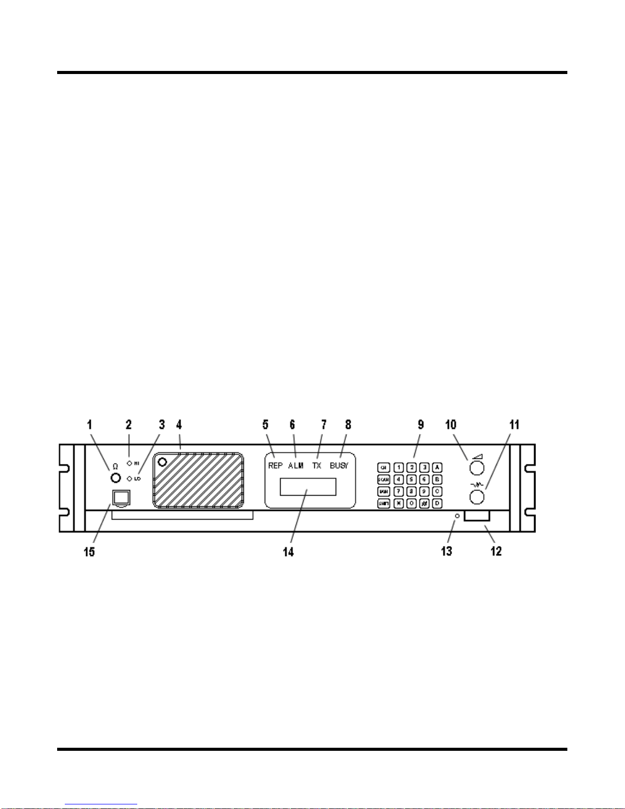
Front Panel Controls
•
1. Headphone Socket
This socket is provided to allow users to lis te n to the Bas e Tech II Base Repeater using head pho nes . P lu gg ing a
headphone into this soc ket will disconnect t he built-In speaker. It does NOT include a microphone input or TX
PTT facility.
2. High TX Power
This is a service point and is not used by the radio operators
3. Low TX Power
This is a service point and is not used by the radio operators
4
Page 5

Base Tech II Base/Repeater Station Operator’s Manual
4. Loud Speaker*
The receiver audio signals are heard from this speaker ( provided that the volume setting is loud enough and
provided that the speaker has not been muted by one of the tone signaling formats).
5. Repeater Mode Indicator LED
The Repeater Mode Indicator LED will illuminate "REP" in
programmed for Repeater operation. This LED is NOT illuminated on any channel that is programmed to
operate in Base mode.
6. Alarm Mode Indicator LED
The Alarm Mode Ind icator LED will illuminate (Flas hing) "ALM" in
fault in the receiver module, the transmitter module, or the PA module on the selected channel.
7. Transmit Mode Indicator LED
The Transmit Mode Indicator LED will illuminate "TX" in
transmitting.
8. Busy Mode Indicator LED
The Busy Mode Indicator LED will illuminate "BUSY" in
receives a carrier signal on the selected channel that is greater than the Squelch setting.
9. Keypad*
The 5 x 4 key Ke ypad is used to enter ch annel se lection, tone inf ormation, an d other da ta int o th e Base Tech II
Base Repeater. Specific key sequences are described fully in section 4 of this document. It includes the
following keys: CH, SCAN, MON, SHIFT, 1, 2, 3, 4, 5, 6, 7, 8, 9, 0, •, #, A, B, C, and D.
10. Volume Control*
yellow
red
whenever the Base Tech II Base Repeater is
green
when the selected channel has been
orange
whenever the Base Tech II Base Repeater
whenever the tra nsceiver detects a
The Volume Control is used to set th e audio output level f rom the loudspeak er. Rotate this knob clock wise to
increase the audio level, or counter-clockwise to reduce the audio level.
11. Squelch Control*
The Squelch Contro l is used to set the squ elch threshold. Select a channel that is not being used and slowl y
rotate this knob clockwise unti l the annoying background noise ceases . It may be desirable to rotate this knob
clockwise, slightly past the squelch threshold, to compensate for varying background noise levels.
12. Power ON/OFF Switch
The Power ON/OFF Switch is used to switc h the Base Tech II Base Repeater "ON" or "OFF ". Pr ess this k nob to
switch the Base Tech II Base Rep eater "ON". Press this knob again to s witch the Base Tech II Base Repeater
"OFF". This knob is slightly more depressed when in the "ON" position.
5
Page 6
Base Tech II Base/Repeater Station Operator’s Manual
13. Power On Indicator LED
The Power ON Indicator LED will illuminate in
position.
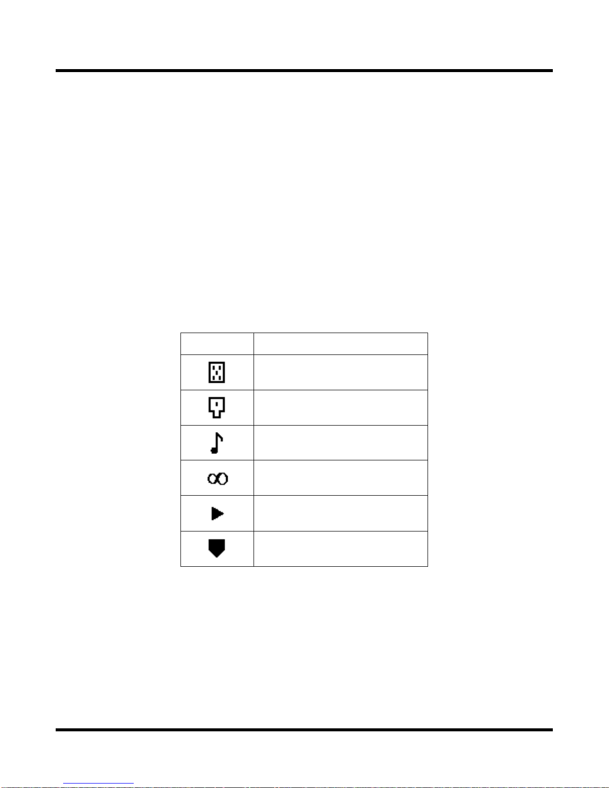
14. Liquid Crystal Display (LCD) (not used on Single Channel Models)
The LCD comprises of four (4) lines each of which is capabl e of disp laying t wenty-one ( 21) char acters. T he first
line, under normal operating conditions, displays the strength of the signal being received on the selected
channel as a bar graph. The second line displa ys the strength of the transmitting power as a bar graph. The
third line displays the selected channel number (up to four characters) in the first five left hand character spaces,
and displays the channel name (up to eight characters) in the next eight character spaces.
Any combination of the following characters may be used in the channel name:
0-9, A-Z, a-z, / + - * # ! $ % ( ) = [ ] < > ? and space
This area of the LCD is left blank when channel names are not used.
The six character spaces on the right hand side of this line are used to display status symbols as follows:
Symbol Status
green
whenever the Power ON/OFF switch is in the "ON"
The monitor status.
The key lock status.
The tone encode status.
The scan mode status.
The high power transmit status.
[SHIFT] key is depressed.
On the left hand side of the fourth line, the t ype of tone sig naling s ystem selected by the user is dis played. For
example, "5TON" indicates 5 Tone signaling while “DTMF” indicates Dual Tone Multi Frequency signaling.
The right hand side of the fourth line is used to display data that the user enters (for example, 5 Tone calling
sequences). These char acter spaces are also used b y the Base Tech II Base Repeater to displ ay messages
and information directed to the user.
15. Microphone Input Socket
Connect the microphone into this socket.
6
Page 7
Base Tech II Base/Repeater Station Operator’s Manual
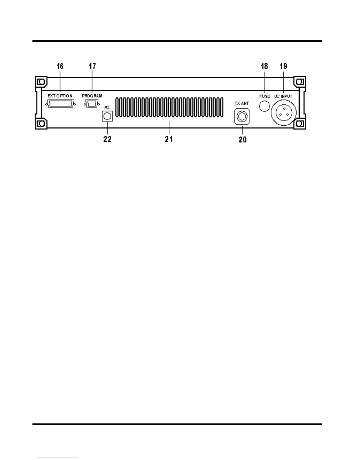
Rear Panel Connectors
•
16. 25 way External Options Connector
17. 9 way Programming Connector
18. DC Input Fuse Holder
19. 3 way DC Input Socket
20. TX/Antenna Connector (N type)
21. Ventilation Slots
22. RX Connector (BNC type)
OPERATION
Installation and Programming
As the Base Tech II Base Repeater can be installed to opera te as either a Base St ation or as a Repe ater, some
of the instructions in this document may apply to one application only, som e may apply in both cas es, while
others may only apply if the particular func tion has been enab led during programm ing of the Base Tech II Base
Repeater.
The Base Tech II Base Repeater must be programm ed before it will operat e correctly. This should be d one by
the equipment supplier or a qualified radio tradesman. They will require the Base Tech II Base Repeater
programming software to do this correctly.
It is important that the Base Tech II Base Repeater be cor rectly installed at its working location by a qualified
radio technician.
As a minimum, it is necessary to:
o Connect the DC Input power lead to a suitab le 13.8 Volt Regulated DC Po wer suppl y that has s ufficient
capacity. (Ensure that the DC Polarity is correct).
o Connect the two antenna c onnectors to suitable antennas (ens ure that the VSWR of the ant ennas is
correct).
o Insert the microphone into the microphone connector on the front panel.
7
Page 8

Base Tech II Base/Repeater Station Operator’s Manual
Basic Operation
Switch On
•
Switch the Base Tech II Base Repeater "ON" b y pressing t he knob (1 2). Then c heck that th e LED ind icator (13)
is illuminated.
Adjust the Volume Setting
•
Rotate the Volume Knob (10) cloc kwise (from the f ully counterclock wise position) until the audio level f rom the
speaker is suitable.
Adjust the Squelch Setting
•
Rotate the Squelch Knob clock wise (f rom the f ully counter clock wise posit ion) slo wly unti l the back ground no ise
can no longer be heard. It is wise to rotate the knob sl igh tly further in the clockwise direction so that variations in
the background noise level do not "break" the sque lch setting and caus e annoying squelc h noises to be he ard
from the speaker.
Select the Channel
•
Select the required chan nel by pressing t he CH ke y followed by the chan nel number k ey. The channel number
keys must be selecte d within tw o seconds. For example, [CH ] + [0] + [1] t o select Chann el 1. T he LCD Dis play
should now display CH01 and (if programmed with a channel label) the channel name: "CH01 NAME".
Receiving
•
You should now be able to hear any radio traffic that occurs on channel #1 on the Base Tech II Base Repeater. It
may be necessary to adjust the Volume setting to suit your listening requirements.
Transmitting
•
Depending on the leg al requirements in your country, and the operating requirements within your or ga ni zat io n, i t
may be necessary to announce your Call Sign. In add ition, it will probably be nec essary to announce the Ca ll
Sign of the party you are calling at the start of your transmission.
When transmitting, it is necessary to hold the m icrophone about 3 inches from your mouth and speak clearly
into the front of the microphone.
It is also necessary to press and hold the “Press To Talk” (PTT) bar on the side of the microphone while
speaking into the microphone.
8
Page 9

Base Tech II Base/Repeater Station Operator’s Manual
Front Panel Operation
This section desc ribes mos t signaling and ot her advanc ed features th at are availa ble on the Bas e Tech II Base
Repeater. The availability of som e features is dependent on the pr ogramming of the transceiv er and installed
options. You may find it worthwhile to discuss these feat ures in detail with your radio su pplier to obtain a full
understanding of their benef its.
Keypad Operation
•
The Keypad is the interface between the user and the Base Tech II Base Repeater. It is used to enable or
disable various functions and to enter the required data for signaling purposes.
The word (5-Tone) or (DTMF) shown af ter the described f eature indicates tha t the described feat ure applies to
the particular signaling format.
The following keys are used for the purposes described:
[0] - [9] Entering new channel numbers
Entering the "KILL" password
Entering signaling encoding numbers (5-Tone) (DTMF)
Entering DTMF numbers (DTMF)
[A] Advancing the Base Tech II Base Repeater to the next higher channel
Entering the signaling "A" tone (5-Tone) (DTMF)
Encodes the "A" Tone (DTMF)
[B] Advancing the Base Tech II Base Repeater to the next lower channel
Entering the signaling "B" tone (5-Tone) (DTMF)
Encodes the "B" Tone (DTMF)
[C] Entering the signaling "C" tone (5-Tone) (DTMF)
Encodes the "C" Tone (DTMF)
[D] Entering the signaling "D" tone (5-Tone) (DTMF)
Encodes the "D" Tone (DTMF)
[•] Displays the previously entered encode numbers (5-Tone) (DTMF)
Encodes the "•" -Tone (DTMF)
[#] Encodes the signaling numbers that are displayed in the LCD display (5-Tone) (DTMF)
Encodes the "#"-Tone (DTMF)
[CH] Used with two channel numbers [0] - [9] to change the active channel o n the Base Tech II
Base Repeater. E.g. [CH]+[9]+[0] will chan ge the activ e channel to Ch annel 90 (pr ovided Ch
90 has been programmed into the Base Tech II Base Repeater.
[SCN] Used to place the Base Tech II Base Repeater into the "All-Scan" mode where the Base Tech
II Base Repeater will scan all programmed channels. Pressing the [SCN] key again will
cause the Base Tech II Base Repeater to exit from the "All-Scan" mode.
[MON] Switches the Base Tech II Base Repeater between "Mon itor ON" mode an d "Monitor OFF"
mode and is used to "Un-mute" the radio when using selective calling (depending on the
programming of the Base Tech II Base Repeater).
9
Page 10

Base Tech II Base/Repeater Station Operator’s Manual
Keypad Operation using the [SHIFT] Key
•
Some of the Base Tech II Base Repeater's features and related f unctions can be c hanged b y using the [ SHIFT]
key. To make thes e changes, it is necess ary to first press the [SH IFT] key followed b y the other k eys within a
two second timeframe.
The following key sequences are used for the purposes described:
[SHIFT]+[0] Toggles the tone system between 5-T one signaling and DTMF signaling
[SHIFT]+[1] Switches the LCD back-light to the ON or OFF position
[SHIFT]+[2] Toggles the transmitting power between High po wer and Low power
[SHIFT]+[3] Invalid Key
[SHIFT]+[4] Toggles between "Sing le Tone Encoding" mode and "5-Tone" or "DTMF" signaling
mode
[SHIFT]+[5] Invalid Key
[SHIFT]+[6] Enters the KILL mode to allow entry of the KILL password
[SHIFT]+[7] Displays the programm ed information for the select ed (active) channel in the LCD
display
[SHIFT]+[8] Locks or Unlocks the Base Tech II Base Repeater's Keypad
[SHIFT]+[9] Toggles the Base Tech II Base Repeater between "Normal Channel Scanning"
mode and "Priority Channel Scanning" mode
[SHIFT]+[A] Restores a channel to the Channel Scanning List. (The user must f irst select the
channel to be restored as the active channel)
[SHIFT]+[B] Invalid Key
[SHIFT]+[C] Indica tes to the Base Tech II Base Repe ater that you have e ntered the l ast num ber
of a DTMF encoding sequence
[SHIFT]+[D] Invalid Key
[SHIFT]+[•] Deletes the active channel from the Channel Scanning List
[SHIFT]+[#] Will attach the "R-Number" data to the active encode number and transmit the
whole sequence
[SHIFT]+[CH] Will start or stop the display of the TX and RX bar graphs in the LCD display
[SHIFT]+[SCN] Will place the Bas e Tech II Base Repeat er in the Progr am Scan m ode or exit f rom
the Program Scan mode
[SHIFT]+[MON] Invalid Key
10
Page 11

Base Tech II Base/Repeater Station Operator’s Manual
Changing Channels
•
To change to another chann el, sim ply press th e [CH] k ey followed by the num ber of the r equired c hannel within
two seconds.
For example: To select Channel 8, press [CH] [0] [8]
To select Channel 99, press [CH] [9] [9]
Note that it is alwa ys necess ar y to enter t wo dig its f or the C hanne l Num ber. The channel # location dis pla yed in
the LCD will become blank as soon as the [CH] key is pressed. The cursor will blink at the location of the
channel number, and display the new numbers as they are entered.
It is also possible to change channels by using the [CH], [A] and [B] keys instead of entering the channel
numbers. Pressing the[CH] then the [A] k ey will advance the channe l to the next higher pr ogrammed channel,
while pressing [B] will advance the channel to the next lower programmed channel.
Note that this action will ignor e channels t hat have not b een program med into th e Base Tech II Base Repeater.
Accordingly, the LCD display may appear to advance more than one channel if the missed channel is not
programmed into the Base Tech II Base Repeater.
Signaling
The Base Tech II Base Repeater includes some very sophistic ated signaling capabilities. W e suggest that you
have your radio supplier conduct some training on the use of these capabilities prior to using them.
While it is possible to use these signaling c apabilities in both rep eater mode, and in bas e station mode, m any
will only be useful in practice when the Base Tech II Base Repeater is used in base station configuration.
The Base Tech II Base Repeater supports the 5-Tone sequential, and/or the DTMF, and the Single Tone
signaling formats . The required signaling format(s) must be enable d when the Base Tech II Base Repe ater is
programmed.
5-Tone Signaling
•
Available Tones
5-Tone signaling is comm only referred to as “S elective C alling” (or S elcall) and usuall y comprises of a series of
5 tones sequentiall y transmitted or r eceived in accor dance with certain int ernational st andards. It is possi ble to
use longer sequences to enhance the signaling capabilities and to provide additional functions.
Accordingly, the Base Tech II Base Repeater will encode up t o sixteen (16) tones and decode u p to eight (8)
tones.
These tones can be any of the following letter/number combinations:
[0] - [9], and [A] - [D]
The most recently entered tone can be recalled and deleted by pressing the [•] key repeatedly.
11
Page 12

Base Tech II Base/Repeater Station Operator’s Manual
Entering a 5-Tone Encode Sequence
When switched "ON" , th e Bas e Tech II Base Repeater carries o ut its s elf - test r outi ne, the n waits rea d y to ac cep t
5-Tone encode numbers. Accordingly, it is necessary to enter the required 5-Tone digits directly using the
keypad, then pressing the [#] key to transmit the 5-Tone sequence. (Up to sixteen digits can be entered).
If it is necessary to enter the "R " number sequence t o activate the repeater, the [SHIFT] k ey must be pressed
before pressing the [#] key.
If a 5-Tone number is NOT displayed in the LCD, and the [#] key is pressed, then the Base Tech II Base
Repeater will recall the most recent 5-Tone number and transmit it.
Recalling the last encoded sequence
Pressing the [•] will recall the most recent 5-Tone encode sequence and display the sequence in the LCD
display. Continuing to press the [•] key will delete t he last digit of the sequence unt il all digits are delete d. In
practice, users will usually delete the last one or two digits before entering the new digits.
DTMF Signaling
•
Available Tones
The following DTMF tones can be used in any number/letter combination:
[0] - [9], [A] - [D], [•], and [#]
NOTE: Tone [B] is NOT available if the "Attach Dec ode No" field in the DTMF Encod e Menu has been set to
"ON".
Up to sixteen (16) DTMF digits can be encoded in one calling sequence.
DTMF Tone Entry
There are two methods of entering DTMF tones. The specific tone encoding format is selected during the
programming of the B ase Tech II Base Repeater in the <Main Menu><Encode Set ><DTMF Encode><Attach
Decode No.> field.
Attach Decode No. "OFF" format
Pressing the PTT lever first automaticall y selects the DTMF encoding for mat and allows direct entr y of DTMF
tones.
Hold the PTT lever on the microphone whi le pres s ing the requ ir ed DT MF tones . T he t ones wil l b e trans mitted as
the keys are being pressed.
12
Page 13

Base Tech II Base/Repeater Station Operator’s Manual
Attach Decode No. "ON" format
Attach Decode No. "ON" autom atical l y enco des th e us er’s DTMF decode n umber after the encode number. This
can be used for any purpose.
Enter the required DTMF tones (up to sixteen ton es, except "B" tone) and then trans mit the total tone se quence
(including the users decode number) b y pressing the [#] key. All tones will be transmitted in one continuous
sequence after pressing the [#] key.
Pressing the [•] key will delete the last number entered.
Always confirm that the LCD is clear before proceeding, as it may take up to 5 seconds for the tones to be sent.
For example, assum e that your d ecode number is 12345, an d that you wish to encode number 12346. You wil l
input 12346, and then press the [#] key. The Base Tech II Base Repeater will encode "12346B12345". The
called radio will disp lay “12345” in their LCD indicating the calling party's number is "12345".
NOTE:
tone.
Pressing the [SHIFT] key and then the [#] will encode ONLY the encode number (and not the decode number).
Redialing with DTMF
If, during the programming of the Base Tech II Base Repeater, the <Attach Decode No> f ield has been set to
"OFF", the redialing function operates as follows:
Press [SHIFT], then press [#] and the Base Tech II Base Repeater will redial the last encoded DTMF number.
If, during the programming of the Base Tech II Base Repeater, the <Attach Decode No> f ield has been set to
"ON", the redialling function operates as follows:
Press [#] and the Base Tech II Base R epeater will redial th e last encode d DTMF number with the Base Tech II
Base Repeater's programmed decode number.
Press [SHIFT], then press [#] an d the Base Tech II Base Repeater will redial the last enco ded DTMF number
without the Base Tech II Base Repeater's programmed decode number.
Restoring the last DTMF number to the LCD Display
It is possible to rest ore the last encode d DTMF number to the LCD display, provided the <Attac h Decode No >
field has been set to "ON" during the programm ing of the Base Tech II Base Repeater. First, confirm that the
LCD is NOT displaying any DTMF numbers. Then press [V] and the last encoded DTMF number will be
displayed in the LCD disp lay. It is possible to e dit this number at this tim e by pressing the [V] key (whic h will
erase the last number) or by pressing the required keys to add additional numbers.
The "B" tone is used as the delimiter in this encoding format and therefore CANNOT be used as a DTMF
Encoding DTMF numbers with the 5-Tone system enabled
It is possible to enter DTMF numbers even with the 5-Tone system enabled. This function must be enabled
during the programm ing of the Base Tech II Base Repeat er by setting the <DTMF Encode> f ield in the <5Tone
Encode Menu> to "ENABLE".
To enter a DTMF number (with 5-Tone signaling enabled), the user m ust pres s the PTT lever whi le enterin g the
first DTMF number. Second and subs equent num bers do NO T r equire the PT T lever to be pr essed, pro vided all
numbers are entered within a few seconds (before the disp lay reverts to 5-Tone mode and displays "5TON" in
the LCD display).
13
Page 14

Base Tech II Base/Repeater Station Operator’s Manual
Single Tone Encoding
•
The Base Tech II Base Repeater has the ability to encode one of six single tone fr equencies for 1, 2, 3, or 4
seconds. This function is enabled during programming of the Base Tech II Base Repeater by selecting the
<Single Tone ON> field in the <Encode Menu>, and setting the encode period.
Press the [SHIFT] and the [4] keys to put the Base Tech II Base Repeater into Single Tone Encoding mode. "S1"
and the tone frequency ("xxxxHz") will be displayed in the tone area of the LCD display for about 4 seco nds un til
the Base Tech II Base Repeater reverts back to the normal signaling mode.
While the Base Tech II Base Rep eater is in Single Tone Encoding mode, it is possib le to advance to the next
tone frequency by pressing the [A] key, or to return to the previous tone by pressing the [B] key.
Pressing the [#] ke y will encode the disp layed to ne (for the programm ed tim e period). It a lso au tomaticall y ex its
the Single Tone Encoding mode and returns the Base Tech II Base Repeater to the normal signaling mode.
Scanning
The Base Tech II Base Repeat er is supplied with two s canning modes. These are Al l Channel Scan mode in
which the Base Tech II Base Repeater will scan al l channels that are progr ammed into the Base Tech II Base
Repeater, and the Program Channel Scan mode in which the Base Tech II Base Repeater will scan onl y the
channels that have been designated dur ing the programming of the Base Tech II Base Repeater. One HIGH
priority and one LOW priority scan channel can be set for each scan mode during the programming of the radio.
All Channel Scan Operation
•
Pressing the [SCAN] key places the Base Tech II Base Repeater into All Channel Scan mode. The Scan m ode
symbol "•" is displayed in the LCD display. Also the LCD will also display "All Scan Mode-in" for two
seconds as shown below:
RX====
TX
CH01
All Scan Mode
In
Program Channel Scan Operation
•
∞
Pressing the [SHIFT] and then the [SCAN] ke y places the Base Tech II Base Repea ter into Program Channel
Scan mode. The Sca n mode s ymbol "•" is displayed in the LCD displa y. The LCD will also displa y "PRG Scan
Mode-in" for two seconds as shown below:
RX====
TX
CH01
PRG Scan Mode
In
∞
14
Page 15

Base Tech II Base/Repeater Station Operator’s Manual
Exiting All Channel Scan and Program Channel Scan modes
•
Pressing the [SCAN] key will tak e the Base Tech II Base Repeater out of either scann ing mode and return the
Base Tech II Base Repeater to normal m ode. The scan s ymbol "•" will be removed from the LCD display. The
LCD will display "Scan Mode-out" for two seconds as shown below:
RX====
TX
CH01
Scan Mode Out
Priority Scanning
•
The Base Tech II Base Repeater allows users to enter the required scanning m ode first, then enable Priority
Scanning for the particular scanning mode chosen.
Pressing the [SHIFT] key then the [9] key places the Base Tech II Base Repeater into Priority Scanning mode as
shown below:
RX====
TX
CH01
Priority Scan
Pressing the [SHIFT] and the [9] key again will take the Base Tech II Base Repeater out of Pr iority Scan mode
and return it to the Normal Scan mode as shown below:
RX====
TX
CH01
Normal Scan
∞
15
Page 16

Base Tech II Base/Repeater Station Operator’s Manual
Removing an Active Channel from the Scan List
•
It is possible to tem porarily delet e an active c hannel fr om the scan lis t by pressing [S HIFT] and the [•] key and
holding them down for more than on e s ec ond . M ult ip le c ha nn els can be del eted f r om the Scan list, prov ide d that
at least one channel remains in the Scan List.
A "beep" sound from the radio confirms correct deletion of the channel from the scan list. This function CANNOT
be used in the Priority Scan mode. The Base Tech II Base Repeater automatic ally restores all channe ls to their
respective scanning list as soon as the Base Tech II Base Repeater exits from the scan mode.
Restoring Channels to the Scan List
•
Channels can be rest ored to the scanning l ist without exiting f rom the scan m ode by pressing the [ SHIFT] ke y
and pressing and holding the [A] k ey for m ore than one s econd. T his action will r estore all channels t o the sc an
list. This action CANNOT be used in the Priority Scan mode.
16
Page 17

Base Tech II Base/Repeater Station Operator’s Manual
Locking the Keypad
Pressing the [SHIFT] k ey and then the [8] key will lock all k eys (except the [SHIFT] and [MON ] keys) on the
Base Tech II Base Repeater's ke ypad to preve nt acci dental or inad vert ent dat a entry. After pressing the [SHIFT ]
and [8] keys, the k eypad becomes locked and the Ke y-Lock symbol “•” is displayed in the LCD display. The
display also shows "Key-Lock" for two seconds as shown below:
RX====
TX
CH01
Key Lock
Pressing [SHIFT] and [8] again will Unloc k the k eypad, rem ove the Ke y-Lock s ymbol from the LCD displ ay, and
display "Key-Unlock" in the LCD display for two seconds as shown below:
RX====
TX
CH01
Key Unlock
Changing Tone Signaling Systems
It is possible to switch the Base Tech II Base Repeater's tone signaling system among 5-Tone sequential
signaling, DTMF signalin g and Non (N o-Tone), providing the <Miscellaneous Menu> <Tone System Change>
field was set to "ENABLE" during the programming of the Base Tech II Base Repeater.
Press [SHIFT] and ho ld down th e [0] key for more than one seco nd t o c ha nge among the 5-Tone system, DTMF
system and Non system. The new signaling system will show up on the LCD display as follows:
RX====
TX
CH01
System is DTMF
Pressing [SHIFT] and holdin g down the [0] key for more than one sec ond again will change the Base Tech II
Base Repeater to the next signaling system . The new signaling system will show up on the LCD display as
shown below:
RX====
TX
CH01
System is Non
17
Page 18

Base Tech II Base/Repeater Station Operator’s Manual
Displaying the Channel Information
The Base Tech II Base Repeater can display inf ormation pertaining to the selec ted channel (pr ovided that the
<Miscellaneous Menu> <Information Display> field was set to "ENABLE" during the programming of the radio).
This information includes:
o The RX frequency of the selected channel.
o The TX frequency of the selected channel.
o The channel spacing for the selected channel (Wide or Narrow).
o The operating mode for the selected channel (Base, Repeater, Simplex, Duplex)
o The RX CTCSS/DCS tone for the s elected channel (provi ded CTCSS/DCS has been pr ogrammed for
use on the selected channel).
o The TX CTCSS/DCS t one for the selected channel (provided CTCSS/DCS has been program med for
use on the selected channel).
o The tone encoding format (providing 5-Tone signaling was selected during programming of the Base
Tech II Base Repeater).
o The tone set (providing 5- Tone signaling was selected dur ing programming of the Base Tech II Base
Repeater).
o The ANI mode.
o The tone decoding set (provi ded 5-Tone or DTMF signaling was selected during programming of the
Base Tech II Base Repeater).
o The decode number (provided 5-Tone or DTMF signaling was selected dur ing pr ogramming of the Base
Tech II Base Repeater).
To view this inform ation in the LCD disp lay, first select the required channe l. Then press the [SHIF T] key, then
the [7] key. You will need to keep the [7] k ey pressed unti l the Base Tech II Base Repeater has cycled throu gh
the information steps.
This function is NOT available if the <Miscellaneous Menu> <Information Display> field has been set to
"DISABLE" during the programming of the Base Tech II Base Repeater.
18
Page 19

Base Tech II Base/Repeater Station Operator’s Manual
Display of Received Tone Frequencies.
It is possible to set th e Bas e Tech II Base Repeater to displa y the rec eived tone fr equenc ies in the LCD disp la y.
They will appear in the area normally used to display the strength of the received signals.
Press [SHIFT] and then press [D] to enable this function.
Once enabled, the LCD wil l show "RCV" in the area of the LCD disp lay that norm ally shows th e strength of the
received signal, as well as, "Tone Display on" for two seconds as shown below:
RCV
TX
CH01
Tone Display On
Whenever a tone frequency is decoded, the frequenc y number will be displayed in the LCD displa y to the right
of "RCV" as shown below:
RCV 12345
TX
CH01
5TON
Pressing the [SHIFT] key, then the [D] key once again will disable this function and retur n the LCD display to
normal as shown below:
RX
TX
CH01
Tone Display
Off
19
Page 20

Base Tech II Base/Repeater Station Operator’s Manual
Bar Graph Displays
The Base Tech II Base Repeater will normall y show the stre ngth of the rece ived s ignal t o the r ight of "RX " in t he
LCD display and the strength of the transmitted signal to the right of "TX" in the LCD display. Both will be
displayed in the form of a bar graph.
This function can be disabled by pressin g the [SHIFT] ke y, then the [CH] k ey. The LCD display will indicate "RX
Display Off" and "TX Display Off" as shown below:
RX Display Off
TX Display Off
CH01
Pressing the [SHIFT] key, then the [CH] key once again will return t he Base Tech II Base Repeater to normal.
The LCD display will show the normal bar graph display for both the RX signal strength and TX signal strength.
LCD Display Back Light
The LCD Display has a Back-Light to illum inate the displa y. It norm ally switches "ON" whenev er any ke y or the
PTT lever is pressed, an d will remain illuminated for f ive seconds. Some users may pref er the Back-Light to
remain illuminated to assist viewing the LCD display in poor viewing situations.
Press the [SHIFT] k ey, then press the [1] key for m ore than one second and the LCD Back-light wil l remain
illuminated.
When finished, press the [SHIFT ] key and then pres s the [1] k ey for more than one second an d the LCD Bac klight will revert to normal operation.
Transmit Power Change
It is possible to change the B ase Tech II Base Repeater's transmit power f rom the high power s etting to t he low
power setting (and vice versa) from the keypad, provided that this function has been enabled during the
programming of the Base Tech II Base Repeater.
To enable this function, the <Miscellaneous Menu> <TX Power Change> field must be set to "ENABLE".
Press the [SHIFT] k ey, then the [2] k ey and the Bas e Tech II Base Repeater will change from the high transmit
power setting to the low transm it power setting. T he "•“symbol will be rem oved from the thir d line of the LCD
display.
Press the [SHIFT] k ey and the [2] k ey a sec ond tim e, and the Base Tech II Base Repeater will change from the
low transmit power s ett ing to t he hig h tr a ns mit power setting. The "•" symbol will be displayed in the third line of
the LCD display.
If this function is NOT required, the <Miscellaneous Menu> <TX Power Change> field must be set to
"DISABLE".
20
Page 21

Base Tech II Base/Repeater Station Operator’s Manual
Calling Party ID Display
The Base Tech II Base Repeater has the capability to display a calling radio's ID (ANI) number after being
called. When the Base Tech II Base Repea ter is call ed, "CALL" will be d isplayed on the fourt h line of the LCD
display (and continue to flash). The calling radio's ID number will be displa yed to the right of "CALL" as shown
below:
RX
TX
CH01
CALL 12346
If the Base Tech II Base Repeater user pres ses the [#] k ey (when "CALL " is flashing and t he caller 's ID number
is displayed), the Base Tech II Base Repeater will automatically call the identified radio.
In the case of 5-Tone signaling systems, this function is enabled in the <5Tone Encode Menu> <Encode
Format> field, by selecting one of the following parameters:
"Encode + B + Decode"
"Encode + A.Pause + Decode"
"Decode + A.Pause + Encode"
"Encode + ANI"
In the case of DTMF signaling s ystems, this f unction is enabled b y setting t he <DTMF Encode Men u> <Attach
Decode No> field to "ON" during the programming of the Base Tech II Base Repeater.
Displaying any Radio's ID Number
The Base Tech II Base Repeater has the capabilit y to display any calling radio's ID ( ANI) number. When the
Base Tech II Base Repeater rec eives an ANI number, "DISP" will be displayed on th e fourth line of the LCD
display (and continue to flash). The radio's ID number will be displayed to the right of "DISP" as shown below:
RX
TX
CH01
DISP 1234
In the case of 5-Tone signaling systems, this function is enabled by setting the <5Tone Decode Menu> <ANI
Receive> field to "ON" during the programming of the Base Tech II Base Repeater.
In the case of DTMF signaling systems, this function is enabled by setting the <DTMF Dec ode Menu> <ANI
Receive> field to "ON" during the programming of the Base Tech II Base Repeater.
21
Page 22

Base Tech II Base/Repeater Station Operator’s Manual
Emergency Caller Display
The Base Tech II Base Repeater has the abilit y to accep t and d isplay em ergency c alls from other rad ios with in
the radio system.
This function is enabled by setting the <Emg Call Receive> field to "ON" in the <5Tone Decode Menu> or
<DTMF Decode Menu> during the programming of the radio.
The calling (Emergency) radio must encode its emergency data in the following format:
"000" + the calling radio's ID (decode number).
This format applies to both 5-Tone and DTMF signaling systems.
When the Base Tech II Base Repeater receives an emergency call, it will sound a warning tone from the
speaker. The LCD will display "EMG" (flashing) in the fourth line, and display the emergency radio's ID to the right
of "EMG" as shown below:
RX
TX
CH01
EMG 12346
Upon receipt of an emergenc y call, th e Bas e Tech II Base Repeater will autom atic ally respond to the em er genc y
radio by sending the emergency radio's ID number to it.
If the Base Tech II Base Repeater user presses the [#] key, the Base Tech II Base R epeater will resend the
emergency radio's ID number.
While the Base Tech II Base Repeater is in the Emergenc y Mode, all k eys (except th e [#] ke y) on the keyboard
become disabled.
Pressing the [SHIFT] key and the [•] key will return the Base Tech II Base Repeater to the norm al operating
mode.
Automatic Transmit in Repeater Mode
The Base Tech II Base Repeat er can be programm ed to automatically repeat vali d incoming messages. F irst,
the active channel of the Base Tech II Base Repeater must be programmed to opera te as a repeater. It must
then receive a carrier frequency on the designated channel. If the Base Tech II Base Repeater has been
programmed for CTCSS or DCS operation, it must also receive a valid CTCSS or DCS tone. It will then
automatically retransmit any received signals.
When the Base Tech II Base Repeater ceases to receive a carrier frequ ency, or a valid CTCSS or DCS ton e, it
activates the <Auto TX Reset Time> timer. This will keep the Base Tech II Base Repeater repeating (for up to
9.9 seconds dependi ng on the programm ing of the Base Tech II Base Repeater), and allow other users with a
valid CTCSS or DCS tone to access the repeater.
22
Page 23

Base Tech II Base/Repeater Station Operator’s Manual
TX Test Mode
The Base Tech II Base Repeater comes equipped wit h a T X ( Transmit) Test Mode. When the Bas e Tech II Base
Repeater is placed in the TX Test Mode, it will transm it a carrier frequenc y modulated with a 1kHz tone on the
selected active channel. It is possible to change channels while in TX Test Mode.
Pressing the [SHIFT] k e y, then the [B] key places the Base Tech II Base Repeat er in TX Test Mode and displays
the message in the LCD as shown below:
RX
TX
CH01
TXT TX Test Mode-in
Pressing the [SHIFT] k ey and the [B] key a secon d time will return the Bas e Tech II Base Repeater t o normal
mode and displays the message in the LCD as shown below:
RX
TX
CH01
TXT TX Test Modeout
Keypad Test Mode
The Base Tech II Base Repeater comes equipped with a Keypad Test Mode that allows the user to elec trically
test all keypad keys as well as the PTT Key.
Holding the [C] key while switching the POWER SWITCH "ON" places the Base Tech II Base Repeater in
Keypad Test Mode and displays the message in the LCD Display as shown below:
KEY TEST
Please Key-in
Then press the keys to be tested one at a time. The res pective k e y will be d ispla yed in t he LCD when t he k ey is
operating correctl y. For example, if you press the [CH] key, the LCD Display will indicat e correct operation as
shown below:
KEY TEST
CH Key
Switch the Base Tech II Base Repeater "OFF" to exit the Keypad Test Mode.
23
Page 24

Base Tech II Base/Repeater Station Operator’s Manual
Frequency Band Test Mode
It is possible to display the Base Tech II Base Repeater's operati ng Freq uenc y Band i n the LC D dis pla y when in
Frequency Band Test Mode.
Holding the [B] key while switching the POWER SWITCH "ON" places the Base Tech II Base Repeater in
Frequency Band Test Mode and displays the operating Frequency Band in the LCD Display as shown below:
<PLL Band Check>>
40D OK
"40D" indicates the frequency band for a particular Base Tech II Base Repeater radio.
Switch the Base Tech II Base Repeater "OFF" to exit the Frequency Band Test Mode.
Starting Message
When the Base Tech II Base Repeater is Switched "ON", it will display a Starting Message in the LCD display for
two seconds. The default Starting Message (using all dots) is shown below:
!!!!!!!!!!!!
!!!!!!!!!!!!
<51BS V095 510>
!
!
!!!!!!!!!!!
A personalized message for your business may be shown as the Starting Message. If you require a
personalized mes sage, then it should be entere d in the < Misce llaneous Menu> <Starting M essage > field dur ing
the programming of the radio. Such a message is shown below:
Securicor Wireless
<51BS V095 510>
Serial Number Display
It is possible to displa y the Bas e Tech II Base Repeater's Serial Num ber in the LCD D ispla y. To do so, the serial
number must be entered into the <Config uration Menu> <Seri al No.> field dur ing the progr amming of the radio.
The serial number can be up to eight characters long and can comprise of any of these characters:
"A - Z" & "0 - 9".
24
Page 25

Base Tech II Base/Repeater Station Operator’s Manual
Holding the [D] key while switchi ng the POW ER SW ITCH "O N" places the Bas e Tech II Base Repeater in Serial
Number Display Mode and displays the Base Tech II Base Repeater 's Serial Number in the LCD Display as
shown below:
Serial KY000727
Switch the Base Tech II Base Repeater "OFF" to exit from the Serial Number Display Mode.
EEROM Data Check Mode
As soon as the Base Tech II Base Repeater is switched "ON", it wi ll autom atic all y read an d check all the dat a in
the EEROM. If this check finds damaged or corrup ted data, the Base Tech II Base Repeater will automatic ally
enter the Programming Mode and display the following message in the LCD Display:
EROM Data Error
Should this happen, it is necessary to return the Base Tech II Base Repeater to your radio supplier or to a
qualified radio trades-person who has the facilities to re-program the Base Tech II Base Repeater.
25
Page 26

Base Tech II Base/Repeater Station Operator’s Manual
Hardware Error Detection
The Base Tech II Base Repeater automatically tes ts for certain hard ware faults or failures , and when a f ault is
found, it will blink the "ALM" LED display abo ve the LCD Displa y and indicate the nat ure of the fault in the LCD
Display as sh own below:
RX
TX
CH01
RX PLL Error
This figure indicates an RX PLL error.
RX
TX
CH01
TX PLL Error
This figure indicates a TX PLL error.
RX
TX
CH01
PA Error
This figure indicates a PA error.
Should the Base Tech II Base Repeater indicate an y of these errors, it is necessary to ret urn the Base Tech II
Base Repeater to your radio supplier or to a qualified radio trades-person to have the fault corrected.
26
Page 27

Base Tech II Base/Repeater Station Operator’s Manual
RS232C Communications Error
If a fault is encountered during program ming of the Base Tech II Base Repeater, one of the following m essages
may be displayed in the LCD Display:
o Over Run Error
o Framing Error
o Parity Error
o Unknown Command
o Data Unmatch
o Send Error
o Answer Timeout
o Receive Timeout
Please switch the B ase Tech II Base Repeater "OFF ", and then back "ON", and tr y re-programming the Bas e
Tech II Base Repeater.
27
 Loading...