

Page 1
HP125 User manual
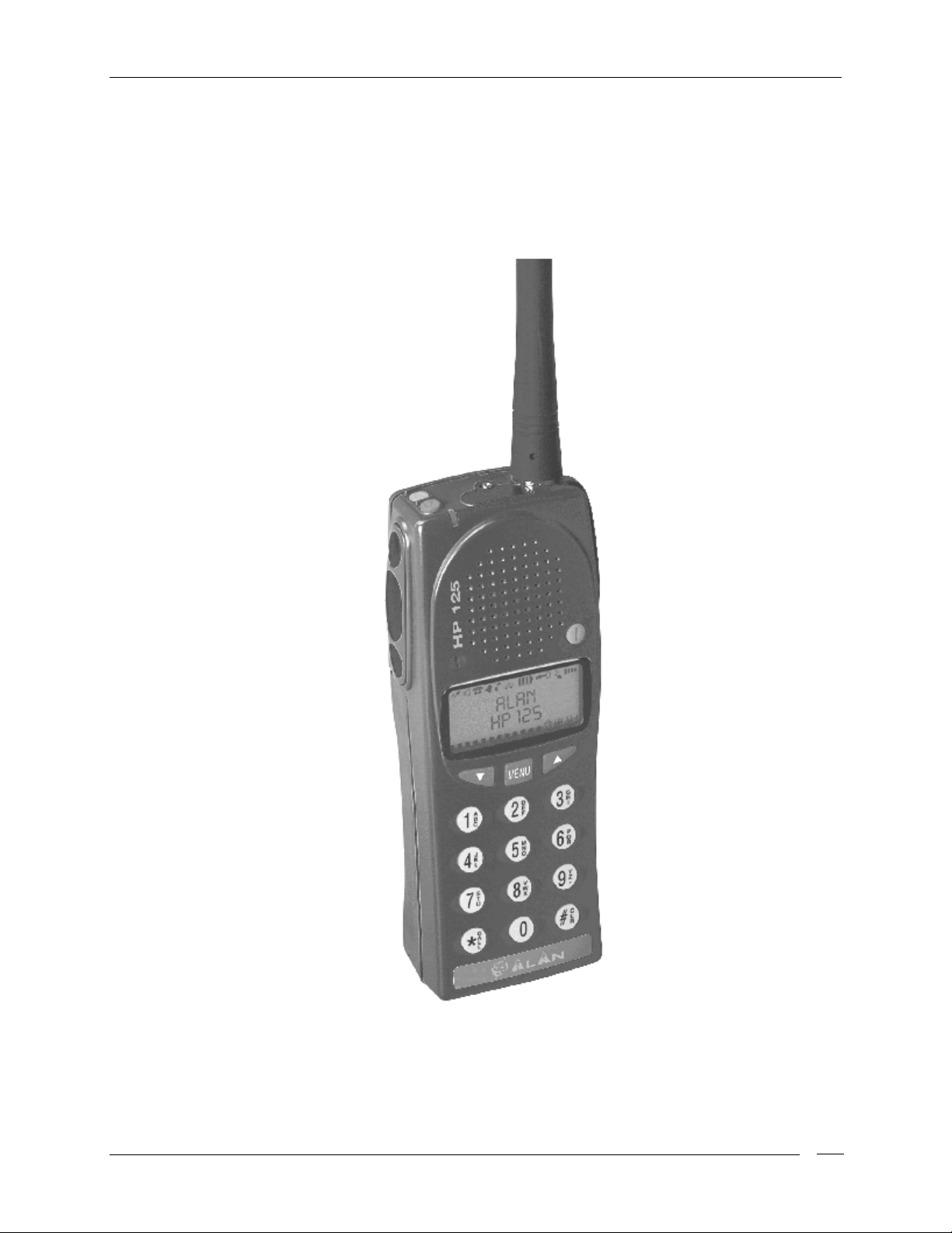
HP125
VHF Handheld PMR Transceiver
User’s Manual
Copyright 1998 by CTE International Italy; all rights reser ved.
Page.
1
Page 2

HP125 User manual
In this book…
User’s Manual..............................................................................................................................................1
IN THIS BOOK…................................................................................................................................................... 2
NTRODUCTION
I
ARNING NOTES
W
AFETY
S
ONVENTIONS AND SYMBOLS IN THIS BOOK
C
PART NAMES AND THEIR FUNCTIONS.......................................................................................................... 7
TOP........................................................................................................................................................................ 7
RONT
F
................................................................................................................................................................... 7
IDE (LEFT AND RIGHT
S
ISPLAY
D
SETUP.................................................................................................................................................................... 10
NPACKING
U
ITTING/REMOVING THE ANTENNA
F
NSTALLING/REMOVING THE BATTERY PACK
I
NSTALLING/REMOVING THE BELT CLIP
I
HARGING THE BATTERY
C
...................................................................................................................................................... 4
................................................................................................................................................... 4
.................................................................................................................................................................. 4
......................................................................................................... 6
)........................................................................................................................................... 8
................................................................................................................................................................. 8
......................................................................................................................................................... 10
....................................................................................................................... 11
......................................................................................................... 11
................................................................................................................. 11
...................................................................................................................................... 12
BASIC OPERATIONS .........................................................................................................................................13
WITCHING THE RADIO
S
ECEPTION
R
DJUSTING VOLUME
A
HANNEL SELECTION
C
DJUSTING SQUELCH
A
RANSMISSION
T
DJUSTING TRANSMIT POWER
A
CANNING CHANNELS
S
ADIO LOCK
R
.......................................................................................................................................................... 13
........................................................................................................................................................ 17
ON/OFF..........................................................................................................................13
............................................................................................................................................. 14
........................................................................................................................................... 14
........................................................................................................................................... 14
.................................................................................................................................................... 15
............................................................................................................................. 16
.......................................................................................................................................... 16
SELCALL AND CTCSS/DCS OPERATION.....................................................................................................18
ECEPTION
R
RANSMISSION
T
.......................................................................................................................................................... 18
.................................................................................................................................................... 18
Sending a Selcall............................................................................................................................................ 18
Stored call (Address book)............................................................................................................................... 18
Who-has-called (Call Queue)...........................................................................................................................19
ANUAL CALL
M
One touch call ................................................................................................................................................20
..................................................................................................................................................... 20
ADVANCED OPERATIONS............................................................................................................................... 21
ENDING STATUS MESSAGES
S
ENDING
S
HECKING
C
ENDING
S
ANDSFREE TRANSMISSION
H
FREE MESSAGES
FFSK
FREE MESSAGES
FFSK
PATTERNS
DTMF
................................................................................................................................. 21
(SDM)...............................................................................................................21
(SDM)............................................................................................................ 22
.................................................................................................................................. 22
(VOX) .....................................................................................................................22
CARE AND MAINTENANCE............................................................................................................................. 24
ATTERY PACKS
B
.................................................................................................................................................. 24
Information on rechargeable batteries.......................................................................................................... 24
Proper charging of battery packs ..................................................................................................................24
Memory effect................................................................................................................................................. 24
Erasing memory effect.................................................................................................................................... 25
Page.
2
Page 3

HP125 User manual
Warnings for battery and charger use........................................................................................................... 25
ADIO MAINTENANCE
R
.......................................................................................................................................... 26
Cleaning battery packs................................................................................................................................... 26
Cleaning the radio.......................................................................................................................................... 26
Connectors...................................................................................................................................................... 26
OPTIONAL ACCESSORIES...............................................................................................................................27
Microphone connector................................................................................................................................... 27
QUICK REFERENCE.......................................................................................................................................... 28
PERATION SUMMARY
O
LCD M
EMO REFERENCE GUIDE
......................................................................................................................................... 28
............................................................................................................................. 28
MAIN SPECIFICATIONS.................................................................................................................................... 30
ENERAL
G
RANSMITTER
T
ECEIVER
R
AF &
M
............................................................................................................................................................. 30
...................................................................................................................................................... 30
............................................................................................................................................................. 30
SIGNALING
ECHANICAL SPECS
................................................................................................................................................. 31
............................................................................................................................................ 31
INDEX....................................................................................................................................................................32
Page.
3
Page 4

HP125 User manual
Introduction
Congratulat ions. HP125 is an advanced PMR (Professional Mobile Radio). It s r ugged design allows it to be
your reliable partner even during hard working days. It s large LCD as well as user f riendly controls make
the HP125 easy t o use.
HP125 is a real system radio, supporting CTCSS/DCS, 5 t one signaling systems (encoder/decoder up to
28 + 28 tones), FFSK, DTMF and trunking system property. Selcall mode supports also many f acilities,
such as an alphanumer ic address book, a call queue function as w ell as a status message table. Y ou can
also use FFSK to send/receive short text messages which you can enter via t he alphanumeric keypad. The
way your radio operat es may be upgraded and may differ f r om w hat is described here.
To extend the flexibility, the radio is provided with VOX function, which allows you to switch on the
transmitter just by talking us ing an optional headset f or f ull hands free operation.
Sinc e st andard operat ion can be changed by programming, the functions of t he r adio and the buttons used
to activate them can be modified t o meet your needs. Please cont act your radio network administ rator or
dealer for f urther det ails.
Transceiver’s specifications provided in HP125 are compliant with ETS 300 086 and ETS 300 113,
moreover its top level design and resistance are compliant with IEC529 level IP54 and MIL STD 810
C,D,E.
CTE Inter na tional is c ommitted t o continuous quality , for this rea son specif ications may var y wit hout pr ior
notice.
Warning notes
Every ef for t has been made t o ensure that the information in this document is complete, accurate, and upto-date. CTE International assumes no responsibility for the results of errors beyond its control. The
manufacturer of this equipment also cannot guarantee that changes in the equipment made by non
authorized people will not af fect the applicab ility of the information in it.
This user’s guide is subject to change w ithout notificat ion. This booklet is refer red to equipment sof tware
version 1. 0. If you own a later one please contact CTE International f or the most recent updates.
Safety
Your HP125 handheld transceiver has been carefully designed to give you years of safe, reliable
perfor manc e. As w ith all electrical equipment, how ever, there are a f ew basic precautions you should take
to avoid hurting yourself or damaging the radio:
Read the instructions
•
Read and follow all warning and instruction labels on the radio itself
•
Do not carry t he transceiver by the antenna
•
Grasp it by its base ( not the tip!) when you need to replace or remove the antenna.
in this handbook carefully . Be sure to save it for f uture refer ence.
.
. This may damage the antenna or antenna terminal.
Do not
•
rad io will per form b es t if the microphone is 5-10 cm away from t he mouth and the r a d io is ver tical.
Be sur e
•
Do not
•
Do not transmit without t he antenna fitted on t he radio
•
transmit the radio with t he antenna ver y close to or touching exposed par ts of the body. The
the PTT key is not pressed w hen you don’t need to transmit.
operate t he radio near unshielded electrical blasting caps or in an explosive atmospher e.
. Although the HP125 is provided with a
Page.
4
Page 5

HP125 User manual
protect ion circuit, damage to the TX final stage could r esult.
Respect the environment conditions
•
. The radio is designed to be used in heavy environments,
however avoid exposure to extremely hot or cold temperatures (out of the range between –30 to
+60°C). Don’t expose the transceiver t o excessive vibr at ions as well as dusty or rainy places.
Never try to disassemble or service the radio yourself
•
(aside from the routine maintenance
described in this handbook). It w ill immed iately void the war ranty and y ou may c a use damage req uiring
extensive repair w or k . Alway s contact your local dealer for as sist ance.
Use only authorized accessories
•
. Non original accessories could seriously damage your handheld
transceiver.
Do not sp ill liquid of an y kind on t his r adio
•
. If your transceiver gets wet immediately dry it wit h a
soft cloth.
Switch the radio off bef ore you clean it
•
. Strictly follow the directions in the paragraph “Care and
maintenance”.
Handle the batter y pr operly
•
Be certain
•
that your power source matches the rating listed for the supplied battery charger (AC
. Str ictly f ollow the dir ec t ions in “Care and maintenance”.
adapter) . I f you are not sure, check with your dealer.
To avoid damaging the power cable of the batt ery charger
•
, do not put anything on it or place it
wher e it will b e walked on.
This product complies with the requir ement s of t he Council Direct ives 89/336/EEC and 73/23/EEC on the
approximation of the laws of t he member states relat ing to electromagnetic compatibility a nd low voltag e.
Page.
5
Page 6

HP125 User manual
Conventions and Symbols i n this Book
!
This sym bol marks a ‘note’. Notes are hints or tips whi ch of fer additional infor m ati on to help y ou.
"
This symbol marks a ‘caution’. Cautions are special notices which you should read and
foll ow caref ully to avoi d possible damage to your equipment and to avoid potenti al danger
to yourself or ot her people.
Key names will be highlighted in
Important sentences and words ar e highlighted in Italic.
LCD messages which may appear on the transceiver ’s display are highlight ed in Courier New
bold
.
Page.
6
Page 7
HP125 User manual
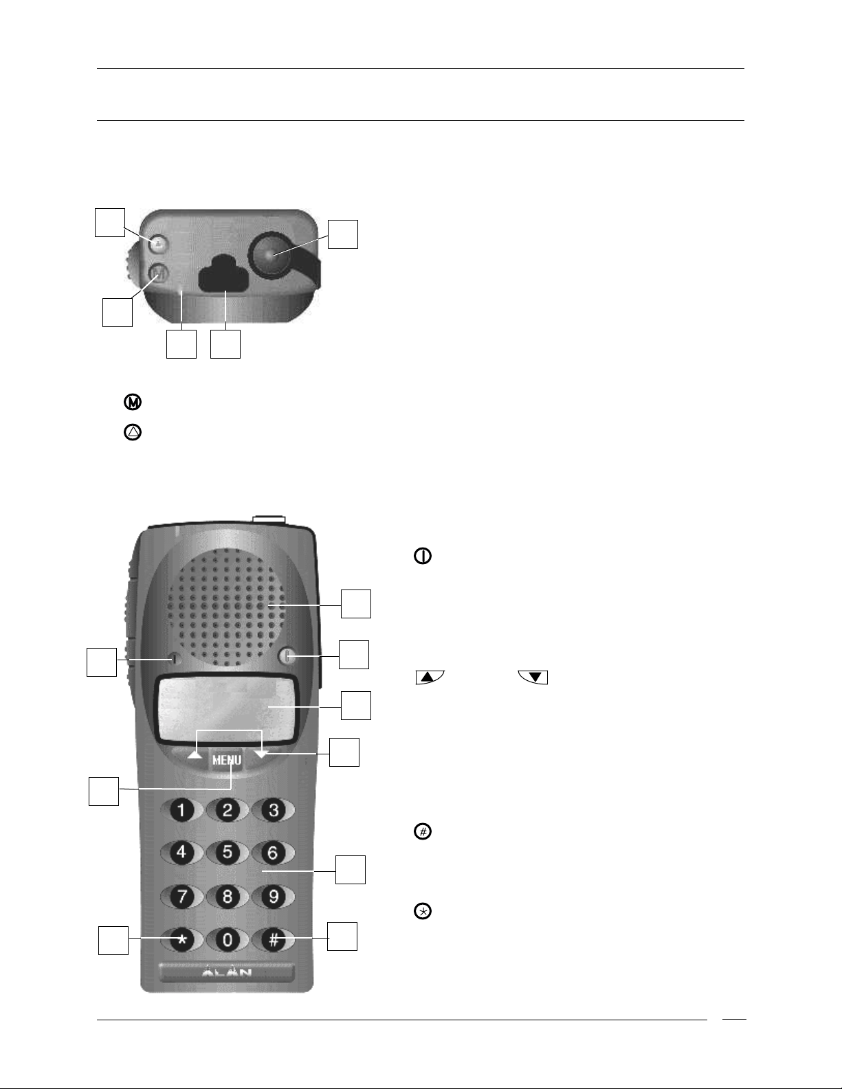
Part Names and their functions
Please have a loo k to the f o llo wing parts des c r ip tion in order to fa miliarize wit h t he transce iver ’s main pa r ts
and contr o ls . Numbe rs in brac k e ts re fer to the illustratio n.
5
4
Status LED
[3]
[4]
[5]
Front
14
3 2
. Glow s in different colors to show the current radio’s status.
Monitor
Emergency
button. Enables t he speaker f or monitoring of the tuned channel.
Top
1
button. Sends an emergency selective c all. (if enabled)
6
7
8
Antenna connector.
[1]
(MX thread type).
Programming connector
[2]
authorized dealers/service facilities only). Allows to
program the radio (channels data) via a suitable
programmer. It must be protected with the supplied
rubber cap when not in use
Speaker
[6]
in speaker located at this point .
[7]
transceiver on and off .
LCD display
[8]
number etc .). Icon and symbols are further explained
in the text “ Display”. Whenever any key is pressed the
display is automatically backlit for a f ew seconds.
[9] UP and
forward and backward through function list and for
changing channels, volume and function values.
. The reception sound is emit ted by the built
Power
button. Press this key to turn the
Fit the antenna to this connector
. Shows the radio’s parameters (c hannel
(under the protect ion cap - for
Down
buttons. For scrolling
13
12
11
9
10
Keypad
[10]
enabled) and letters for the related operations (e.g.
SDM messages or Address Book). Whenever any key
is pressed the display is automatically backlit for a few
seconds.
[11]
command mode, r adio reverts back to st andby mode.
In Selcall mode, deletes incorrectly entered digits (if
Selcall is e nable d).
[12]
selective call features. (Selcall - if enabled)
MENU
[13]
Microphone
[14]
detects your voice.
. For entering digits of selective call (if
Clear
button. If pressed for two seconds in
Call
button. To send a valid call when using
button. Allows accessing the main menu.
. The microphone located in this place
Page.
7
Page 8
HP125 User manual
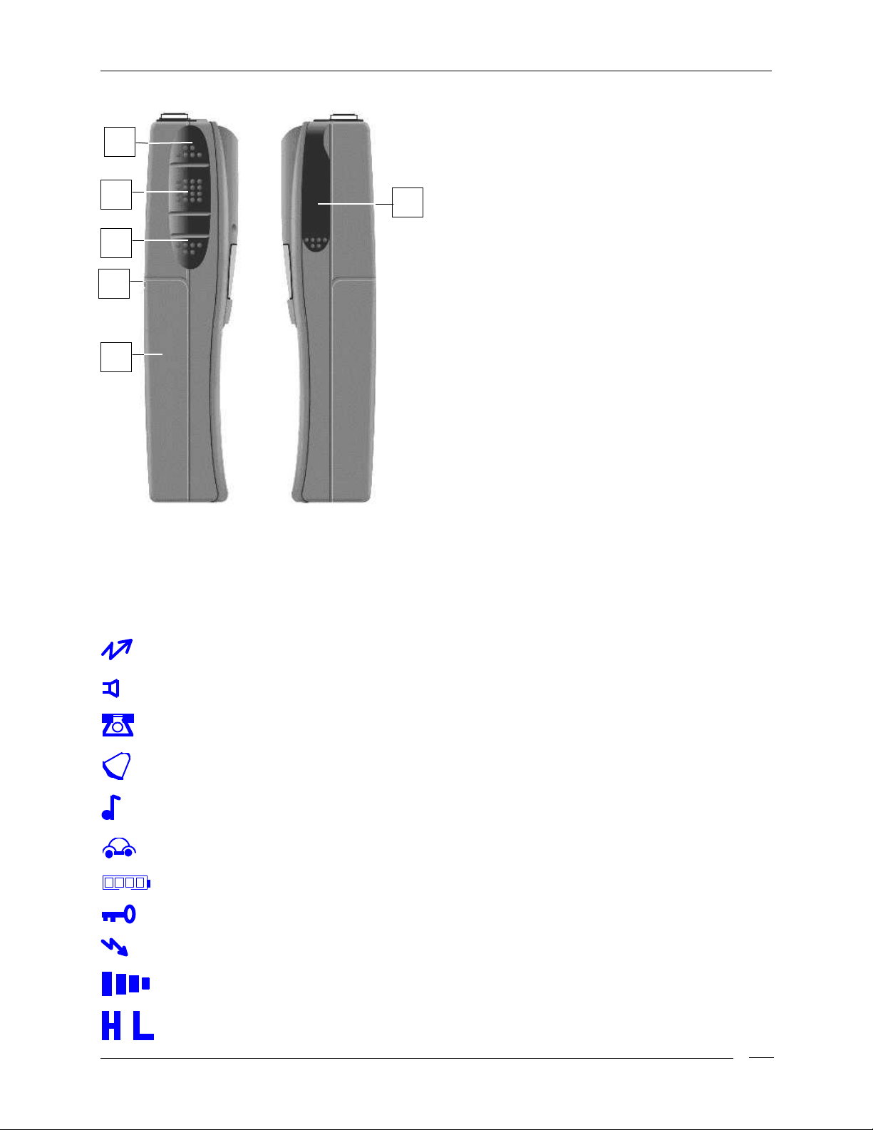
Side (left and right)
20
19
18
17
16
15
Microphone connector
[15]
speaker/microphone, headsets f or VOX use and
other accessories. It must be protect ed with the
supplied rubber cap when not in use. For the
related pin connections please see to
“Microphone connection”.
Battery pack
[16]
energy to your radio.
Release
[17]
Allows for removal of the battery pack.
CALL 1
[18]
(if enabled)
PTT
[19]
[20]
(Push To Talk) button. Switches the
transceiver from receive to transmit when
pressed.
CALL 2
(if enabled)
. This NiMH battery pack supplies
button (located on the batt ery’s body).
button. Sends the selective call NO.1.
button. Sends the selective call NO. 2.
. For remote
Display
This sect ion explains the meaning of the various indicators w hich may appear on the LCD of y our HP125
handhel d trans cei v er :
Radio is transmitting
Speaker is enabled
DTMF is enabled
CTCSS /DCS tone de tect ed
Selective call detected
Scrambler enabled
Battery Level indicator
Keypad lock enabled
Receive mode
(squelch is open)
(status L ED will glow red at the same time)
(yo u w ill hear a udio c o mmunications and/or noise)
(t he number of bar s will vary with level of c har ge )
Reception field strength level
Tr ansmit output power
currently selected, respect ively high (H) or Low ( L)
(t he number of bar s will vary with rec e ive strength)
Page.
8
Page 9

HP125 User manual
Mail n o tific ation
Customizable operation
Volume level
(t he number of bar s will vary with volume level)
Page.
9
Page 10

HP125 User manual
Setup
Unpacking
The following it ems are in the package:
(a) Transceiver’s main body
(b) Flexible antenna
(c) Bat t er y pac k NiMH 1,200 mA/h
(d) Standard batter y charger composed by t w o par ts:
• Cradle
• AC adapter
(e) Belt clip
(f) User’s guide (t his book!)
If something is missing please prompt ly advise your supplier.
Page.
10
Page 11
HP125 User manual
Fitting/removing the antenna
To fit the antenna:
1) Locate the ant enna terminal ( t hread MX connector) on transceiver’s top.
2) Hold the transceiver w it h one hand and the base ( the thicker par t ) of the ant enna with the other one.
3) Attach the included f lexible antenna to t he antenna terminal by tur ning the ant enna clockwise until it is
firmly locked. Don’t overtighten the antenna!
To remove the antenna revers e the previous step.
"
Leave the antenna attached on the radio. You can not communicate without it. Moreover,
transmitting without the antenna may damage the TX f inal stage. For the same reason us e only the
supplied antenna.
!
The suppli ed antenna is broadband type and cover s the whole spectrum. The antenna does not
need any ali gnm ent.
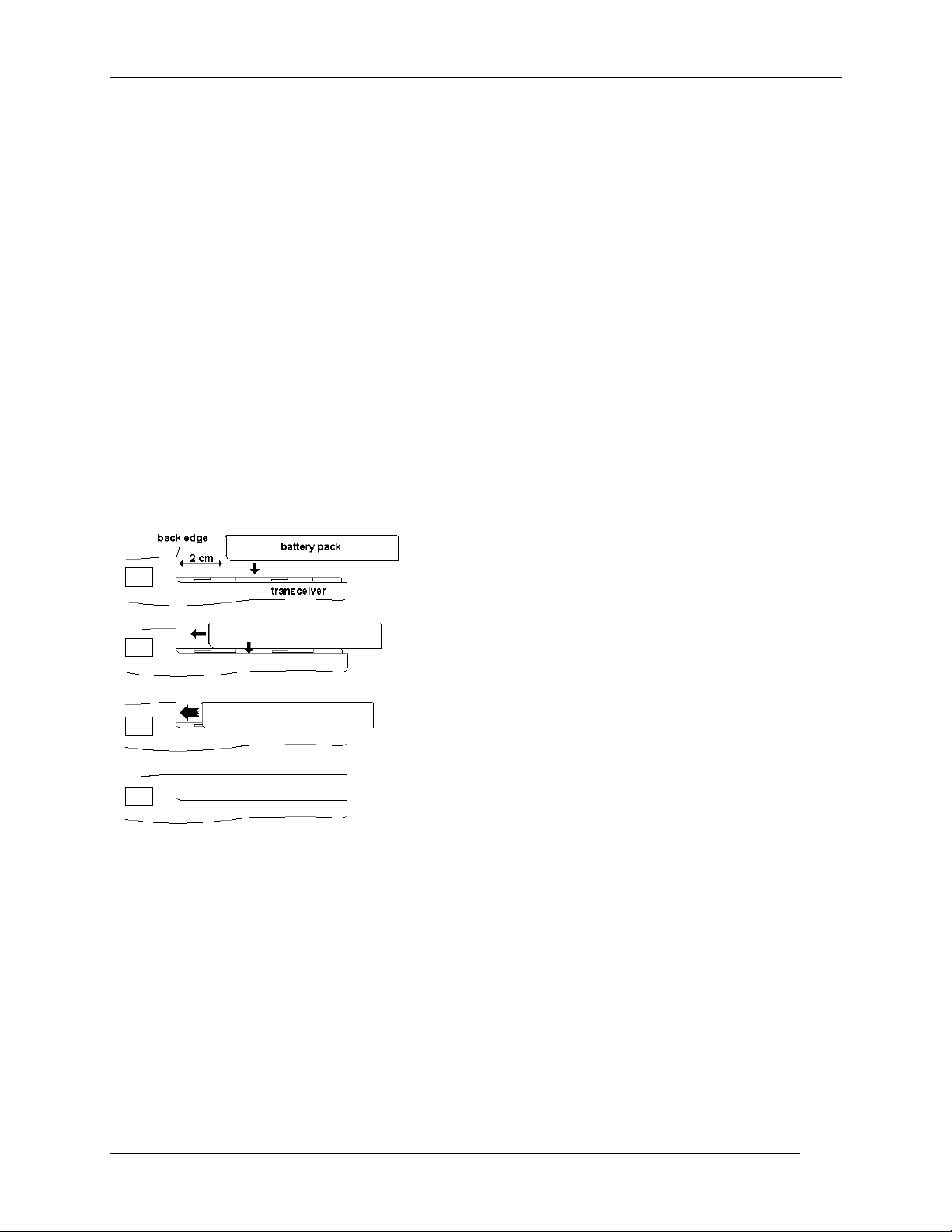
Instal ling/removing the ba ttery p ack
To install the batt ery pack
1
2
3
4
1) Pres s t he batter y r elease button located in the back of t he batter y pac k.
Keep the button pr essed
2)
(the opposite operat ion of the previous st ep 2) : it will stop at 1.5 c m ap p r o ximat e ly and will be f ree.
3) Remove the battery pack by separ at ing it from the transceiver’s body.
(please s ee the fi gure):
1) Hold the transceiver’s body with one hand and the bat tery
pack with the other. Put the battery p a c k onto the metallic
back of t he tr ansc eiver as shown at approximat ely 2 cm
from the bottom edge of the thick par t of the transceiver .
2) Gently slide the battery pack toward the transceiver’s
bottom edge keeping it slight ly pressed onto the metallic
back surface.
3) At approx. 1.5 cm you will feel the bat ter y’s guides f itting
with the transceiver’s guides (the battery pack will be
closer to the transceiver). Keep sliding the battery pack
towar d the back edge.
4) At t he end you will hear t wo clicks: the batt ery pack w ill
snap into place and should be firmly locked.
To remove the bat t er y pack
and gent ly pull t he bat tery pack aw ay from the transceiver bott om edge
:
Installing/removing the belt clip
The supplied belt clip allows you to hang t he transceiver on your belt or jacket w hen y ou are not using t he
radio.
To fit the belt clip
1) Remove the ba ttery pac k as e xplained in “ Installing/removing the bat tery p a c k ” .
2) Just gently slide the clip into the appropriate guides located in the transceiver’s back until it firmly
onto the transceiver ’s body:
Page.
11
Page 12

HP125 User manual
locks.
To remove the belt clip
1) Remove the ba ttery pac k as e xplained in “ Installing/removing the bat tery p a c k ” .
2) Reverse step 2.
Do not forget to remove the batt ery pack befor e fitting/ removing the belt clip, otherwise the
"
operatio n will b e h a rder to perform.
:
Charging the Battery
To charge the supplied battery pack you have to setup the supplied standard charger and connect the
radio as follows ( please see t he picture):
1) Connect t he jack coming from the AC adapter t o t he cradle’s
socket located in its right side.
2) Connect the AC plug of the AC adapter’s pow er cable into an
AC pow e r outlet : the built-in green LED of the cr a d le will glow .
3) Ensure that the radio is switched off. Insert the radio into the
cra dle w ith t he keypa d to wa rd y ou (t he three met allic conta cts of
the battery pack must touch with the three contacts inside the
cra d le): the built-in red L ED o f the cr a d le will glow.
4) Wait 8- 9 hours and remove the radio after that time.
!
Do not remove the radio before 8 hours, otherwise the
battery’s duty could be temporari ly reduced.
Do not forget t o r emove the radio af t er 9 hour s.
"
The bat t er y char ger is for indoor use only.
"
For maximum battery life please see the chapter “Care and M aint enance”.
"
Page.
12
Page 13

HP125 User manual
Basic Operation s
This section describes how the standard operations work. Programming can change standard operation.
Functions of the radio can be modified via an IBM compatible PC. For this reason the way your radio
operates may be upgraded and may slightly differ fr om what is described here.
!
IMPORTANT: Due to the full programmability of the radio, certain menu commands could be
unavail able. E.g. i f your radi o has not been programmed f or selective cal l operations, the rel ated
menu commands won’t be recalled. In case of doubts please contact your dealer/radio network
administrator for f ur ther detai l s .
Switching the radio ON/OFF
To switch the radio on:
1) Hold the (power) button until the radio is switched on: the LCD will start an autotest showing in
sequence:
• A welcome message (if previously pr ogr ammed – it is usually your company name or your per s onal
sta tion identif ic a tion). At the sa me time all the LCD ic o ns will be show n fo r one seco nd as LCD test.
• The firmware release number (FW Rev.).
2) Af t er t he autotest has been carried out the LCD will steadily show the following data:
CHANNEL 1
H
The battery level
•
The channel name/number
•
identification name), it could be the last recalled channel or a previously programmed specific
channel.
The curr ent volume level
•
• The curr e ntly selected TX output power: L (low) or H (high) in the lower right corner of the LCD.
To switch the r adio of f
Reception
. (number of bars indicate level of charge)
on the first line (a specific twelve alphanumeric characters
with an LCD bar indic at ion.
Press and hold the key until the transceiver sw itches off.
Your radio could be previously programmed to w or k, c hannel by channel, in “Open traff ic” , “ CTCSS/DCS” or
“Selcall” mode. Please have a look at each description and as k your radio networ k manager or dealer which
mode your radio channels wor k.
OPEN TRAFFIC
•
selec ted channel. When any signal is received yo ur squelch will unmute and you will s ee in the LCD
the icon (speaker enabled), (squelch is open), (recept ion field strength level – the
number o f bar s will vary ac c o rding to the rece ived s ig nal strengt h). Moreover y o u w ill s e e the s tat us
: in this case you will hear any communication which will be transmitted on the
Page.
13
Page 14

HP125 User manual
LED glowing gree n and you w ill hear the messag e.
CTCSS/DCS
•
use par ticular TX signaling (a continuous sub-audible tone for CTCSS or a digital code for DCS) as
an access “key” t o work a repeater (encoder) or to unloc k the party’s signaling sensitive squelch.
This last condition allows sharing more radio netw orks in the same frequency. In this case you will
receive only messages coming f rom parties sending a proper TX signaling. Please see the chapt er
“Selcall Operation” for f urt her details.
SELCALL
•
tones” and DTMF Selcall or a frequency shift signaling for FFSK) to call a particular station or
gro up(s) . I n this cas e yo u will rec eive only calls pr ovided w ith your id entif icat ion selec tive call co de
(a number) or calls sent to the group you desire. For further details please see the chapter “Selcall
operation”.
(Cont inuous Tone Code Squelc h System - Digital Coded Squelch): are syst ems which
(Selective call): is a system which uses a signaling sequence (e.g. audio tones for “5
CTCSS/DCS
!
CTCSS/DCS
"
however they are just useful to avoid disturbing stations not owning of the same network
with messages not related to them. In any case, if more than one station is transmitting at the
same time, this will cause interference. Do not transmit if the status LED is glowing or the
icon is on the LCD. Wait until channel is clear before transmitting.
Selcall
and
and Selcall al low to share more than one radio net work in the same frequency,
can be combi ned together.
Adjusting volume
When no keys are pres sed for 5 sec onds, the radio is in its normal stand by condition and t he (up)
and (down) keys are used to adjust the RX volume. To adjust the volume repeatedly press the
(up) key to increase or the (down) key to reduce the volume. The bar meter
is provided in the bottom of the LCD to continuously show the volume
level. The number of bars will vary depending on volume level.
Channel selection
If your radio has been programmed with mor e than one channel, you can easily change it . As previously
explained, each channel can be identified by alphanumeric names which are previously defined by your
network manager or supplier.
To select a channel:
Channel
1) Press the
Channel. Press the key to increase the channel (number) or t he k ey t o decr eas e it
2) . Pr ess t he (clear ) key for tw o seconds to escape the command mode
!
After 5 seconds, if you have not press ed any keys, the radi o automatical ly rever ts back to standby
mode.
MENU
key in order t o access the command menu and see on the display the message
H
Adjusting squelch
Squelch is provided to silence your radio when you are working in open traffic mode (please see
Page.
14
Page 15

HP125 User manual
“Reception”) and no signals are received. It’s very important to adjust the squelch to a level in order to
assure you a stable silence in stand-by condition. If the squelch level is too high, you might lose weak
signals . A good squelch adjustment assures also proper scanning operation.
To adjus t the squelch:
1) Ensure that no c ommunications are carr ied out in the tuned channel (the icon should not be present
in the t op r ight part of t he LCD).
2) Press the
“Squelch”. You will als o s e e a number, which is t he sq uelch adjust ment le vel.
3) Press the key r epeat edly t o dec r ease t he squelch level: after t he level 1 you will se e OFF squelch
is disa b led a nd yo u will a ls o s e e the icon .
4) Press the key repeatedly in order to select the minimum squelch level in which the . icon
disappears ( level 2 nor mally).
5) Press the (clear) key f or t wo seconds to escape the command mode.
!
After 5 seconds, if you have not pressed any k eys, the com m and m enu i s automatic al ly escaped
!
In case of either CTCSS or Selcall system pr ogr am m ed, squel ch does not af f ect the speaker status,
because the radio is closed awaiting the correct tones. In case of advanced signaling systems,
please, pay attention to the programm i ng of the monitor key f unction (fur ther described) . Depending
on this, you m ay or m ay not be able to press the button to mute/unmute the loudspeaker and to
adjust the squelch level. The set squelch level will be stored and recovered at every switch on
operation.
MENU
key in order to access the command menu and see on the display the message
3
Squelch
H
Transmission
When you need to transmit please get used to following all these steps:
1) Ensure that the channel is not busy. ( Other wise y ou will c reat e an int erf erence. Please wait f or t hat
condition).
2) Press the
3) Start talking at a normal voice l evel at approximately 10 cm fr om the microphone (keep the
pressed).
4) When your message is over, release t he
!
Do not shout! It will not increase the distance you are able to communicate. Shouting into the
micr ophone will only make your transmission sound distorted!
!
Don’t release the PTT before your message is over or start talking before pressing it, otherwise
your message will be “chopped”.
!
A PMR handheld radio doesn’t normally allow you to talk and receive simultaneously, for this
reason make your messages short.
!
The radio might be progr ammed with a timeout timer which will automatically switch your radio to
receiv e mode i f you talk too much (af ter a preset tim e). In this case r elease the PTT and wait for a
few seconds: the radio TX features will be automatically reset. Ask the network administrator or
your dealer for fur ther details.
PTT
key: the status LE D will glow red.
PTT.
PTT
key
Page.
15
Page 16

HP125 User manual
g
Adjusti n g T r ansmit Power
Your HP125 can tr ansmit w ith t wo power levels according to the distance of your par ty’s st ation( s). Low
and High levels can be defined by default during pr ogramming. We recommend, when possible, to use the
Low pow er : it w ill increas e t he batt er y lif e and will r educe t he r isk of inter fer ence w ith s ta tions not in y our
radio network w hich may be sharing the same channel w ith you.
1)
Press the
cursor on either L or
MENU
key to access the command menu and see on t he display
H.
Power.
Yo u will also see a
H Power L
2) Change the pow er as f ollows:
• If the
• If the
3) Press the ( clear) key f or about 2 seconds to escape the command menu and restore the radio to
normal standby operation.
!
After 5 seconds, if you have not pressed any k eys, the com m and m enu i s automatic al ly escaped.
Adjusti n g display contrast
Yo u can adjust the LCD contrast in or d er to o b tain the best rea da b ility. It will vary depending on your use as
well a s the environment illumination.
LOW
move to H.
HIGH
move to L.
power is currently selected, press the key to set to high power; the cursor will
power is currently selected, press the key to set to low power; the cursor will
1) Repeatedly pr ess the
message Contrast.
2) Press the key r epeat edly t o increase the contrast or t he key t o decr eas e it.
3) Press the (clear) f or 2 seconds key to escape the command menu mode.
!
After 5 seconds, if you have not pressed any k eys the comm and menu is automatical ly escaped.
MENU
key in order to access the command menu and see on the display the
Contrast
H
Scanning channels
If you have more t han one channel progr ammed, your HP125 can scan them. The advanced scan functions
of the radio allows you to optionally preset two gr oups (g1 and g2).
1) Repeatedly pr ess the
Scan g1.
2) Activate the scan as follows:
MENU
key in order to access the command menu and see on the display g2
2Scang1
H
Page.
16
Page 17

HP125 User manual
• If you have only one gr oup available pr es s t he key.
• If you have two groups progr am m ed, pr ess to scan the g2 group or to scan g1.
• If you simultaneously want to scan the 2 groups, pres s and hol d g1 or g2.
In bot h case s you will se e Scanning and the channel names cycling continuously on the display. The
scanning starts from the lowest address number toward the highest. If one or more priority channels
have been programmed, it will s tart from the f ir s t prio rity addr es s number .
3) To stop channel scan Press the
!
If you are worki ng in Open traff ic (please s ee the paragr aph “Reception”) ensure that the squelch is
properl y set, other wise the scanning may not work properl y. See the paragr aph “Adjusting squelch”
for more details.
!
If CTCSS/DCS or Selcall have been previously programmed, the scanning will stop only if the
receiv ed si gnal has the appropriate si gnaling.
!
If you pr ess the PTT during channel scan, scanning will stop and transmi t in the pri ority channel or
in the fi r st avai lable vacant channel, depending on programm ing.
!
Channel scan can be programmed by your radio network administrator or dealer in a variety of
different parameters depending on your needs. For example he can assign one or more priority
channels, adjust the scan speed (switching tim e), the resum e time ( the time the radi o wai ts befor e
scanning resumes after receiving a signal), set busy or vacant channel stop etc. Please contact
your admi nistrator/deal er f or f ur ther detai ls.
MENU
key, or the
PTT
.
Radio lock
Your HP125 has been provided with a secur ity function which pr otect s it against unauthorized or accidental
activation of commands. Y ou can lock the radio in two ways:
• Full lock: every command is locked.
• Partial lock: only the keypad is locked.
Every time you unlock the radio you will have to enter a 4 digits security code called PIN (personal
identification number).
To lock the radio:
1) Repeatedly pr ess the
Lock P.
2) Press the key to activate the Full lock or the key to activate the Partial lock.
To unlock the r adio
1) I f the radio is in Partial lock press t he
2) Enter the PIN (fo ur d ig its), the ra d io will be unlocked.
!
If you entered the correct pin then the radi o will return to normal operation mode. If you entered the
wrong pin radio remai ns locked.
MENU
key t o access the command menu and see on the display the message F
FLock P
:
MENU
key: the dis pla y will rea d PIN ....
H
Page.
17
Page 18

HP125 User manual
Selcal l and CTCSS/DCS Operation
Reception
During CTCSS/DCS and Selcall operation the radio may be set-up so that the appropriate CTCSS/DCS and
Selcall decoder enables t he speaker. Speaker w ill rema in mut ed until t he cor rec t CTCSS t one, t he c orr ect
DCS code and/ or the appropriat e selective call is r eceived. In case of unmuted speaker, t he message w ill
be hear d, the status LE D will glow g reen and the r e c e ive ic o n w ill be dis playe d. M or eover the st re ngth
level of the received signal is displayed (the number of bars will vary according to the received
signal s trength). The CTCSS/DCS reception is indicat ed by the icon; t he Selca ll rec ept ion is indicat ed
by the icon.
Transmission
Sending a Selcall
You can send a selective call in many different ways which makes it easy and quick to send your calls
depending on your needs:
Stored
call, (who- has called),
Manual
call and
One touch
call.
Stored call (Address book)
This mode allows y ou to originat e a call by using a convenient alphanumeric address book which has been
programmed by your radio network administrator or dealer with the most used ID associated to an
alphanumeric label, for example:
Headoffice 15
John 01
Mary 07
Mike 08
Robert 05
..... XX
..... XX
!
Starting from now, as “ addr ess” we mean an ID associated with an alphanumer i c label.
To call an addr es s using the addr es s book:
1) Repeatedly press the
AddrBook Ok.
2) Press the key t o ac cess the address book.
MENU
key to access the command menu and see on the display the message
AddrBook Ok
H
3) Select t he required address to call (name with associated ID); you have t wo choices:
• Scrolling trough the vari ous addr es ses by means of the and keys.
• Recall ing the i nitial letter of the addres ses. Pr ess the ke y w hich stat es t he initial let te r ( e.g . t o ca ll
Page.
18
Page 19

HP125 User manual
M
ary press
5,
to c all John pres s
4
etc.). The unit will displa y the fir st name of the address book
start ing w ith the selected character (or the next address if no names beginning with t he selected
character is in the list). If the initial letter is the 2nd of the 3rd one print ed on a key, pr ess r espec t ively
that key two or three times (e.g. to recall the Headoffice pr ess 3 twice). If you have more than one
address beginning with the same initial letter use the key to scroll down names till you will
reach the proper address.
4) Press the (call) but t on for 2 seconds to call t he selected address.
!
If you made a mistake in recal ling an address y ou can abor t the call oper ati on at step 4 by pr essing
the (clear) button.
!
Address book is also useful in reception. When you receive a Selcall ID which is stored in the
Note
: the selected address becam e the default TX address.
address book, your radi o will automatically look for that ID in the address book. If it is stored, you
will see the alphanum eri c label on the display as well. For exampl e, i f you r eceive 15 as cal ler ID,
and it is stored in your address book as “ Headoffice”, y ou will see “Headoffice” in your LCD instead
of “15” .
Who-has-called (Call Queue)
This is a co nvenient f acility w hich is useful to c he ck who has calle d you and eventually c all back him/her.
First of all please note that your HP125 has a memory which holds the last 10 received calls :
st
1
(most recent received call)
nd
2
rd
3
th
4
th
5
th
6
th
7
th
8
th
9
th
10
(oldest r ec eiv ed c al l )
John
Robert
Mary
Headoffice
Lyndsay
Mike
Branch
William
Ann
Peter
This buff er memory is displayed similarly to the address book and is a FIFO (First I n First Out) t ype. This
means that the 10th stored addr ess (t he oldest received call) is the first w hich w ill be dele te d af ter t he 11
received call in order to make room for it.
In the example the 1st received call came fro m Pete r, so it w ill be de lete d fr om t he call queue as so on as a
new call is received. All the other addr esses (Names with associated I Ds) will be shift ed one po sitio n down
in order to make room for the new address at the 1st position.
Page.
19
th
Page 20

HP125 User manual
Before a received cal l Aft er t he cal l r ecei ved fr om Fred ( I D 23)
1
2
3
4
5
6
7
8
9
10
st
nd
rd
th
th
th
th
th
th
John 01
Robert 05
Mary 07
Headoffice 15
Lyndsay 21
Mike 08 6
Branch 33 7
William 55
Ann 16
th
Peter 19
To call an addr es s using the c all queue:
1
2
3
4
5
8
9
10
st
nd
rd
th
th
th
th
th
th
Fred 23
John 01
Robert 05
Mary 07
Headoffice 15
Lyndsay 21
Mike 08
Branch 33
William 55
th
Ann 16
1) Repeatedly press the
MENU
key to access the command menu and see on the display the message
CallQueue Ok
H
CallQueue Ok.
2) Press the key to access the call queue. This acce s s is o nly allo wed if the CallQueue is not e mpty.
3) Scr oll through t he address by using the and keys and select the address you want to call.
4) Press the (call) button to call the selected address: it w ill be c alled a nd automat ically de lete d fr om
the call queue.
!
If you need to delete an address stored in the call queue without calling it perform the previous
procedure. At the step 4 press the (clear) button: the selected address will be deleted.
!
The call queue is provi ded with a “space save” functi on: if mor e than one call has been recei ved
from the same caller “space save” will overwrite it.
Manual call
If the radio netw ork administr ator or your dealer has enabled in your unit the manual definition of var iable
address digits:
1) Just dial the variable address digits us ing the keypad before sending t he call. Any digit can be correct ed
by overwriting.
2) When you see the correct address on the display, make the call by pressing t he (call) button.
!
To repeat the last call, just press the button twice. (The group tone (‘A’) can be obtained by
pressi ng and hol ding the 0 key).
One touch call
To activate the “One Touch call, pres s either the
CA LL1
or
CA LL2
but ton. I f they have been progr ammed
the preset address es will be automa tically c a lled .
Page.
20
Page 21

HP125 User manual
Advanced Operatio n s
In this se c tion we’ll d es c ribe so me a dvanced oper at ion which you can do with your handheld tr ansceiver:
Sending status messages
Status digits allow you to transmit some previously programmed conditions in w hich you could momentarily
be: BUSY, FREE, EMERGENCY etc . Y our transceiver can automatically associate the s aid digits with t he
related alphanumeric message in or der to make it easier to send and recognizing them exac tly as you do
with the address book.
To send a st at us message
1) Repeatedly pr ess the
message StatusDig Ok.
2) Press the key to access the status digit command.
3) Press either the and keys to scroll through the various programmed messages and select
the one you wish to transmit.
4) Press the (call) button to select the status digit.
5) Press the (clear) button for 2 seconds to escape command menu mode.
6) Refer to “Sending a Selcall” to address the call.
butt on, the status digit /digit s will be auto matically s e nt to t he sele c ted address.
:
MENU
key in order to access the command menu and see on the display the
StatusDigOk
H
Select
the required address t o call, press the (call)
Sending FFSK free m essag es (S DM )
1) Repeatedly press the
Send SDM Ok.
MENU
key to access the command menu and see on the display the message
Send SDM Ok
2) Press the key to edit the SDM.
3) Edit t he text of SDM by using the key pad as f ollows .
• Press t he key which states each required letter/number (e. g. use 5 to select M, N, O or 5). If the
letter is the 2nd, the 3rd or the 4th one print ed on a key, pr ess r espec t ively that key two, three or four
times (e.g. to recall the H press the key 3 twice). Aft er one second the cursor will automatically
move to the next position.
• To select a dot press the key 9 three times.
• To select !, ? or a s pace, repeatedly press t he key 0 unt il the requir ed char acter appears on the
LCD.
• If you have made a mistake in editing the message, you can delete character s by briefly pressing
H
Page.
21
Page 22

HP125 User manual
the (clear) button.
4) Press and hold the (call) button for 2 seconds to send the SDM.
5) Press and hold the (clear) button for 2 seconds to escape t he command menu mode.
Checking F F S K free messages (SDM)
When you receive an SDM (FFSK message) you will s ee it on the LCD. A ny key w ill dele te it ; Yo u can see
the last 5 received messages at any time. SDM messages are queued in a FI FO call queue similar t o t he
one dedicated for the selective calls (please make refer ence to “ Who-has-called call” in t he chapter “Selcall
and CTCSS/DCS Opera tion”). To r ec a ll it:
1) Repeatedly press the
MSGQueue Ok.
2) Press the key to access t he message queue. This acces s is only allowed if t he MSGQueue is
not
empty.
3) Scr oll through t he messages by using t he and keys and select the one you want to see.
4) Press the (clear) button for 2 seconds to exit the command menu mode.
MENU
key to access the command menu and see on the display the message
MSGQueue Ok
H
Sending DTMF patterns
DTMF (Dual Tone Multifunction Frequency) is a standard signaling system used to dial telephone numbers
over a normal PSTN landline. In radio communications it can be also used to do the same if your radio
channel is connected t o a landline via a suitable device (phone patc h). DTMF is used to send/receive r adio
commands or provide signaling similarly to selective calls. For further details please contact your net work
administrator.
To st or e or dial a DTM F pat t er n:
1) Repeatedly press the
DTMF Send Ok.
MENU
key to access the command menu and see on the display the message
DTMF Send Ok
2) Press the key to edit the DTMF pattern to send.
3) Edit t he DTMF patter n to send by using the keyboard. Pres sing
Any digit can be corrected by overw r iting.
4) Press and hold (call) button for 2 seconds to send the DTMF pattern.
5) Press and hol d the (clear) button for 2 seconds to escape the command mode.
H
or
buttons, you can digit * or #.
Handsfree transmission (V OX )
VOX (Voice Operated Transmit) is an automatic system which allows you to automatically switch the
transmission in hands free mode just by speaking in the built-in mic rophone of a headset (not provided with
Page.
22
Page 23

HP125 User manual
the unit). Please ensure that the handset is suitable for your transceiver as reported in the paragraph
“Microphone connection”.
To adjust the VO X sensitivity
1) Connect the optional headset with built-in microphone to the microphone connector located on the
transceiver’s side.
2) Repeatedly press the
VOX.
Yo u will s e e
OFF
:
MENU
key to access the command menu and see on the display the message
(disabled) or digit w hich indicates t he microphone sensitivity value.(OFF-9)
OFF
Vox
3) Ensure that the headset ’s built-in micr ophone is loc at ed close t o t he side of your mouth.
4) Press either the and keys to adjust the VOX sensitivity in order to ensure a stable
transmission w hen speaking w it h a normal voice level.
5) Press and hold the (clear) button for 2 seconds to escape the command mode.
"
We recommend setti ng t he V OX to lowest sensi tivity possible; t oo high a value could cause
acci dent al transmissions, especially i n hi-noise environments.
H
Page.
23
Page 24

HP125 User manual
Care and Maintenance
Battery Packs
Information on rechargeable batteries
• When t he battery pack is new it does not provide 100% of its ef ficiency. To reach the f ull batt ery
life you must “run-in” the battery with at least 3-4 deep charging/dischar ging cycles, after that it will
reach its maximum capacity. Please see “Proper charging of battery packs” f or f urther details.
• Should you proper ly use the battery pac k, y ou will obta in a t lea st 400 c harge/ disc harge cycles (300
with the optional r apid charger) .
• Nickel-Metal-Hydride rechargeable battery packs lose their charge with time if left unused (selfdischarge),
stored energy in few days.
Proper charging of battery packs
this is normal.
A NiMH (Nickel-Metal-Hydride) battery can reduce 10 to 20% of its
1) Ensure that the radio is switched off; otherwise switch it off by holding the (power) key pressed
(release it af t er the radio is switc hed off) .
2) I nsert the radio into t he cradle as explained in the paragraph “Char ging the battery pack”
3) Wa it t he necess ary time t o pr ovide a f ull charge . I f t he pa ck isn’t co mplete ly disc harged y ou w ill need
less than 8 hours. Evaluate the time by using the battery level indicator and common sense.
"
Do not overcharge the battery: always remember to remove the radio after the necessary
time.
"
The batter y charger i s for i ndoor use only.
!
When possible, charge the battery when it is fully discharged. The battery’s duty could be
temporari ly reduced. Pl ease s ee the paragr aph “ M em or y effect”.
!
Don’t rem ove the radi o before the necessar y time, otherwise the battery’s duty could be temporari ly
reduced. Pl ease s ee the paragr aph “ M em or y effect”.
Memory effect
The supplied NiMH (Nickel Metal Hydride) battery pack is made with a more advanced technology than
normal NiCd (Nickel Cad mium) batt er y. For this r easo n it is virt ually f ree of w hat is called “memor y ef f ect ”,
which af fects NiCd batteries. Memory ef fect is a temporar y capacity reduction which r educes t he batter y
duty. Memory effect may occur just if you regularly charge the battery w hen you haven’t discharged it at
least at 50- 70%. Memory eff ect c an be easily avoided by following these simple rules:
• When possible charge battery packs only when they are completely discharged, i.e. when the
batter y icon has no bar s inside.
• Don’t r emove the battery f r om the charger before the necessar y t ime to pr ovide a full charge.
• Provide at least two deep charge/discharge cycles per mont h.
• The best way t o avoid memory effect is to use two batt ery packs and alternate their use with the
Page.
24
Page 25

HP125 User manual
rad io. T his will allo w y ou to keep on your transceiver’s operation by replacing t he battery pack just
when it’s fully discharged and us e the s pare (charged) one. At t he end of your working day you will
charge the discharged pac k f or 8 hours.
Erasing memory effect
Memory effect can be easily erased just by applying 3-4 deeper charge/discharge cycles:
1) Use the battery fitted in the radio and wait until the radio switches off. Do not stop w hen the last battery
bar disappears f r om the icon; wait until the LCD completely disappears.
2) Wait at least one hour and then try t o turn t he r adio on by pressing the butt on: yo u w ill note t ha t
some energy has restored in the battery, because the radio can be sw it ched on.
3) Leave the radio in RX until the r adio sw it ches off again.(usually af t er a few minutes)
4) Repeat s t eps 2 and 3 three times.
5) Fully charge t he batt ery f or 9 hours and c he ck the bat ter y duty. I f so me memory ef fect still exist s go
back to st ep 1.
!
If the battery duty doesn’t i mprove af ter three cycles, your battery pack is faul ty or has reached the
end of life (pl ease s ee “ Infor m ati on on r echar geable batteries”).
Warnings for battery and charger use
Please use these caut ions to avoid damaging batter y packs or t he transceiver:
"
Before using the bat t er y charger careful ly read any rel at ed warning or cauti on.
"
Don’ t short bat t er y terminals: thi s may cause fire, burns or expl osions.
"
Never dispose of batteries into f ire they may explode causing, burns or expl osi ons. Stri ct ly
foll ow any disposal regulati on of your country.
"
Use only authorized bat t er ies and charger s. The use of non-author ized accessories may cause
burns, fir e or expl osions; causing serious damages to the radio/ batter y or serious injur ies to
yourself.
"
Battery chargers are for indoor use only.
"
Be certain that your power source matches the rati ng listed for t he supplied bat tery charger
(AC A dapt er ) . If you ar e not sure, check with your dealer.
"
To avoi d damagi ng the power cabl e of the battery charger, do not put anyt hing on i t or pl ace
it where it will be walked on. Insert the plug in socket provided with grounded connection.
"
. Do not use the char ger if it has fal len down or it appears damaged; immediately contact an
authori zed service station.
"
Never t ry to disa ssemble or service the charger by yourself. A lw ays cont act your local dealer
f or assistance.
"
To reduce the risk of electric shocks disconnect t he pl ug bef or e any cleaning or maintenance.
Grasp the plug ( not the cable) to remove the plug fr om the socket.
"
Do not expose batteries directly to temperatures below -20°C (-4°F) or greater than 35°C
(95°F) dur i ng their use and do not charge them outside the range of + 5 t o + 55°C ( 41- 131°F) .
Page.
25
Page 26

HP125 User manual
Radio maintenance
Cleaning battery packs
Wipe the battery c ontacts with a clean and lint f r ee c loth t o remove dirt, grease or any other mater ial w hich
may prevent a good electrical contact. If contacts are very dirty you can also w ipe them using a soft pencil
eraser (not hard eraser s for ink!) . If you feel that batt ery contacts ar e not working properly, please contact
your authorized dealer .
"
Do not use li qui d, alcohol or aerosol cleaners.
Cleaning the radio
• Wipe the r adio with a clean and lint free cloth to remove dust. I f it is very dirty, you can use a damp
(slightly moistened with water) cloth.
"
Do not use li qui d, alcohol or aerosol cleaners.
!
If you nor mall y use your r adio i n dusty or hard envi ronments, we do r ecommend usi ng the optional
carrying case. Please s ee “ O ptional accessori es”.
Connectors
When t he connect or s ar e not being used, they should be fitted w it h the supplied cover caps.
"
Only authorized accessories should be connected to the rel at ed connectors.
Page.
26
Page 27

HP125 User manual
Optional accessor ies
These optional access or ies can be used to improve the transceiver’s per f or mances:
• Spare batt er y pack.
• Rapid charger.... Recharges the battery pack in 1 hour and provides trickle charge when the battery
pack reached a full charge.
• Carrying case.
Microphone connector
The microphone connector is designed for the connection of two basic accessories (not supplied as
standard):
An external speaker/ microphon
•
of the supplied belt clip.
e, which allows using t he r adio firmly secur ed to your belt by means
A headset wit h built-in microphone
•
please see “Hands f r ee t r ansmission ( VO X) ” .
Any kind of accessory for the above stated purposes can be connected to the microphone connector,
provided that they meet the following requirement s:
• Jack connec t or s for Speaker (SPK) and Microphone (MI C) must b e res pect ively standar d typ e 3.5 mm
and 2.5 mm. and connected as follows:
• The suggest ed speak er input impedance is 8 Ohms
• The microphone should be condenser low-impedance t y pe.
• Any accessory should be of high quality suitable for professional use.
"
Please don’t connect any accessory which you are not sure meet the above stated
requirements. You could cause serious damages to your radio. In case of doubt please
contact your aut hor i zed dealer.
, which additionally will ad d t he “
MicGND
Spk GND
MIC
VOX”
SPK
fac ility. For furt her det ails
Page.
27
Page 28

HP125 User manual
Quick reference
Operation su m mary
Yo u s hould now be familiar wit h your transceiver . Now you know how ver y eas y it is to use one of its menu
commands. Follow this quick reference.
1) Pres s r epeat edly t he
2) Perform one of the following act ions:
• If t he related message is followed by Ok, pr ess t he key to enter the setting.
• If two arrows are present in each side of the LCD, press either or respectively to
decrease or increase the sett ing.
• If two parameters appears in each side of the LCD, press either or respectively to
activate the left or r ight parameter.
3) If necessary do w hat is described for t hat particular setting press and hold (ca ll) butto n in ca se of
DTMF s e nding).
4) To exit fr om the menu command pr ess and hold the (clear) key for 2 seconds.
MENU
key unt il the required setting appears on the LCD.
LCD Memo reference guide
As soon as you have read the entire manual, the following table references the meaning of each LCD
message to help you quickly locate each funct ion / setting. This is just a memo, for further details please
see the related paragraph.
Page.
28
Page 29

HP125 User manual
LCD Message Description For full details please see…
Channel
Squelch
Power
Contrast
g2
Scan
F Lock P
AddrBook Ok
CallQueue Ok
g1
Operating channel selection (if more than one previously
programmed). Use
Squelch (audio mute in open traffic mode) adjustment. Use
and to select the level.
Allows adjusting the transmission output power. Use
to select L (Low) or
Display contrast adjustment. Use
Channel scanning. If you have only one programmed group use
to activate the scanning. If you have two groups, press to
scan group 1 or
scan both.
Radio lock against misuse. Press
to lock the entire radio.
(Selcall) Display the preprogrammed Address book. Press
access the book, then use
the address to call Press and hold the
(Selcall) Display the addresses of the last 10 received addresses
(to recall the callers). Press
and
call, or Press and hold the
to select an address. Press and hold the key to
and to select the needed channel.
and
H
High).
(
and
to scan group 2. Press and hold g1 or g2 to
to lock the keypad only or
and
to access the call queue, then use
key
to delete it.
to select it.
or the keypad to select
key to call the address.
to
Channel selection
Adjusting squelch
Adjusting transmission power
Adjusting display contrast
Scanning channels
Radio lock
Stored call
Who-has-called call
StatusDig Ok
Send SDM Ok
MSGQueue Ok
DTMF Send Ok
VOX
(Selcall) Sends the previously programmed status messages. Press
to access the status list, then use and to select the
needed status. Press and hold the
status.
Allows editing an FFSK text message (SDM). Press
editing the message (use the keypad to edit). Press and hold the
key to send the message.
Display the last 5 received FFSK messages. Press
the message queue, then use
messages.
To edit and send a DT MF pattern. Press
pattern (use the keyboard to edit). Press and hold the
Allows selecting the VOX sensitivity for handsfree operation
(through an external headset). Use
level. Press and hold
key to escape command mode.
key to confirm the selected
to start
to access
and to scroll through the
to start editing the
to send.
and to select the
Sending status messages
Sending FFSK free messages
Checking FFSK free messages
Sending DTMF patterns
Hands free transmission
Page.
29
Page 30

HP125 User manual
Main Specificatio n s
General
Frequenc y Bands VHF ( HP125): 136÷174 M Hz (136÷162 / 146÷174 MHz)
Number of Channels mor e t han 100
Frequenc y Control synthesizer
Modulation System F3E / G3E
Channel spacing 12.5 / 25KHz
Temperature Range - 30 / + 60 ° C operat ive, -40 / + 80 °C st or age
Humidity 90% not condensing @ 40°C
Power Supply NiM H batter y 1, 200mA/h
RF Impedance 50Ω
Antenna socket MX thread type
Freq uency Stabilit y bet ter than ± 2.5ppm
Transmitter
Output Power 5 W , High / low level programmable channel dependent
Modulation Sys t em FM (F3E) / PM ( G 3E)
Ma ximum Devia tion ±2.5 KHz@12. 5KHz, ±5 KHz@25KHz
Adjacent Channel Power < -60dBc
Spur ious Emissions Switching < 0. 25µW 9KHz÷1GHz, < 1µW 1÷4GHz
Bandwidth full band
Receiver
Circuit Ty p e Double Conversion
Intermediate Frequencies I: 45 MHz, II: 455 kHz
Sensitivit y < 0. 25 µV @ 12 dB SINAD
Intermodulation Rejection > 65dB
Spurious Response Rejection > 70dB
Adjacent Channel Selectivit y > 60dB 12.5KHz, 70dB 25KHz
Switching Bandwidt h full band
Squel ch t hre sho l d 0.1 8µV
Page.
30
Page 31

HP125 User manual
Squelch hysterisis < 3d B
AF & si g n a ling
Audio power > 500mW @ 10% distort ion
CTCSS sensitivity < 6 dB S inad
CTCSS sele c tivity acce pt tones + /-0,5%
Selcall s e nsibility > 99 % @ 1 2 d B Sinad
> 95% @ 10 dB Sinad
Selcall s e le c tivity accept tones +/- 1 ,5%
reject tones +/-3%
Mechani cal Specs
Size (mm) 148 x 36 x 60
Weight 385 g.
Display backlit LCD 2 x 12 char alphanumeric
Keyboard 12 + 3 f unction key s + UP/DOWN/MENU
keys + Emergency key
Batter y back slide battery
Radio and key paint grease r esist ant
Shock resistant follow MIL STD 810
Water & dust IEC529 IP54
Environment al: IEC529 IP54 and MIL STD 810 C,D,E
Page.
31
Page 32

HP125 User manual
Index
A
Address book 18
Adjusting
Display Contrast 16
Squelch 14
Transmission Power 16
Volume 14
Antenna
fitting/removing 11
B
Battery charger
rapid (optional) 27
standard 12
Battery pack
Charging 12
Battery packs
cleaning 26
Erasing memory effect 25
Information on rechargeable batteries 24
Memory effect 24
Proper changing 24
Warnings for battery and chargers use 25
Belt clip 11
C
Call Queue 19
Care and Maintenance 24
Carrying case 27
Channel selection 14
Cleaning the radio 26
Connectors 26
Contrast
LCD adjusting 16
Conventions and Symbols 6
D
Display 8
Adjusting contrast 16
DTMF
Sending patterns 22
F
FFSK
Checking free messages 22
Sending free messages (SDM) 21
H
Handsfree transmission (VOX) 22
L
LCD
Adjusting contrast 16
Page.
32
Page 33

HP125 User manual
M
Memory effect 24
Microphone connector
27
O
Optional accessories 27
Carrying case 27
Rapid charger 27
Spare battery pack 27
Output power
Adjusting 16
P
Part Names and their functions 7
Power
button 13
ON/OFF 13
TX output adjustment 16
Q
Quick reference 28
LCD memo reference guide 28
Operation summary 28
R
Radio lock 17
Radio maintenance 26
Rapid charger 27
Reception 13
S
Safety 4
Scanning channels 16
SDM
See
FFSK, Sending free messages (SDM)
Selcall
Address book 18
Call Queue 19
Manual call 20
One touch call 20
Reception 18
Sending a Selcall 18
Sending status messages 21
Transmissi on 18
Sending
a Selcall 18
DTMF patterns 22
Setup
Battery pack 11
Belt clip 11
Charging the battery pack 12
Fitting antenna 11
Package contents 10
Unpacking 10
Specifications 30
AF & signaling 31
General 30
Mechanical specs 31
Receiver 30
Transmitter 30
Page.
33
Page 34

HP125 User manual
Squelch adjusting 14
Stored call (Address book) 18
Switching the radio ON/OFF 13
T
Transmissi on 15
Transmission Power 16
V
VOX 22
W
Warning notes 4
Warnings for battery and chargers use 25
Page.
34
 Loading...