

Page 1

Midland
HM35 Series – User’s Manual
Model 70-3350
Model 70-5445
Vehicular VHF Transceiver
Vehicular UHF Transceiver
User’s Manual
Copyright © 2004 by Midland Radio Corporation; all rights reserved.
This device complies with part 15 of the FCC Rules
Operation is subject to the following two conditions:
1. This device may not cause ha rmful interference,
and
2. This device must accept any interference
received,
including interference that may cause undesired
operation.
Rev. 2.0 on 1 March 2004 Page 1 of 32
Page 2

HM35 Series – User’s Manual
FCC RF EXPOSURE
The FCC has adopted a safety standard for human exposure to RF energy. Proper operation of this
radio under normal conditions results in user exposure to RF energy below the Occupational Safety and
Health Act and Federal Communication Commission limits.
Mandatory Safety Instructions to Installers and Users:
This radio is
is restricted to occupational use and work related operations only. Radio operators must have the
knowledge to control their exposure conditions and the exposure conditions of bystanders and/or
passengers to satisfy the lower exposure limit allowed for General Population. To comply with FCC RF
exposure limits,
is within 94 centimeters (38 inches) of the antenna. The antenna supplied by the manufacturer or radio
dealer must be mounted at a location such that during radio transmission, no person or persons can
come closer than the above indicated minimum safe distance to the antenna, i.e. 94cm. To comply with
current FCC RF exposure limits, the antenna must be installed at or exceeding the minimum safe
distance stated above, and in accordance with the requirements of the antenna manufacturer or
supplier.
Vehicle Installation Instructions:
The antenna used for this transmitter must be mounted on the center of the roof ONLY and must be
installed in vehicle having the following characteristics in order to prevent bystanders and passengers
from being exposed to levels exceeding the limits for General Population/Uncontrolled Exposure
environment:
All passengers must be sitting under a solid metal roof.
Rooftop width must be at least 76 inches OR the edges of the physical boundary of the vehicle must
be at least 76 inches apart.
DO NOT
one supplied or recommended by the manufacturer or radio dealer. The antenna gain must not exceed 0
dBd. By not following the antenna recommendations you may be exposing person( s) to excess radio
frequency radiation. You may contact your radio dealer or the manufacturer for further instructions.
DO NOT
50% of the time can cause FCC RF exposure compliance requirements to be exceeded. This radio is
transmitting whenever the
microphone normally causes the radio to transmit.
Note: The preceding information is provided to make you aware of RF exposure and how to
ensure that this radio is operated within FCC RF exposure limits.
You, as the qualified end-user of this radio device must control the exposure conditions of bystanders to
ensure the minimum separation distance, stated above for satisfying FCC RF exposure compliance, is
maintained between the antenna and nearby persons. Transmit only when all person(s) are at least the
minimum distance from the properly installed, externally mounted antenna.
operate the radio without the proper antenna installed. Do not substitute any antenna for the
transmit more than 50% of total radio use time (50% duty cycle). Transmitting for more than
approved for use by the general population in an uncontrolled environment. This radio
NOT
DO NOT
operate the tra nsmitter of this mobile radio when a person outside the vehicle
icon is displayed on the LCD. Pressing the PTT switch on the side of the
TX
IMPORTANT SAFETY INFORMATION
CAUTIONS
The antenna connector must be snugly tightened to maintain proper electrical connection and
moisture resistance.
Equipment must be grounded according to Midland Radio Corporation installation instructions for safe
operation.
Equipment should be serviced only by a qualified technician. Refer to radio service manual for
additional information on installation and safety precautions.
WARNING!
!
DO NOT
exposed body parts while the radio is transmitting
!
DO NOT
trigger blast i n g c ap s or c au s e an ex pl os i o n.
!
DO NOT
Note: The above warning list is not intended to include all
hazards that may be encountered when using this radio.
allow the antenna to touch or come in very close proximity with the eyes, face, or any
operate the radio in explosive or flammable atmospheres. The transmitted radio energy could
allow children to operate or play with this radio.
Rev. 2.0 on 1 March 2004 Page 2 of 32
Page 3

HM35 Series – User’s Manual
In this manual…
1 GENERAL INFORMATION FOR THE HM35 SERIES....................................................................................5
2 ABOVE ALL… SAFETY!................................................................................................................................ 6
2.1 Conventions and Symbols Used in This Manual...........................................................................................................6
2.2 Warnings.......................................................................................................................................................................6
2.3 Security.........................................................................................................................................................................6
2.3.a General precautions.........................................................................................................................................6
2.3.b Operating conditions/usage..............................................................................................................................6
2.3.c Installation........................................................................................................................................................7
2.4 Assistance.....................................................................................................................................................................7
3 PARTS OF THE RADIO AND THEIR USE.....................................................................................................8
Front panel..............................................................................................................................................................................8
Rear panel..............................................................................................................................................................................8
4 CHECKING THE PARTS..............................................................................................................................10
5 ADVICE FOR INSTALLATION .....................................................................................................................11
6 BASIC OPERATIONS................................................................................................................................... 13
7 USE OF COMMANDS/OPTIONS.................................................................................................................. 16
8 CUSTOMIZATION.........................................................................................................................................20
9 USE WITH CTCSS/DCS AND/OR SELECTIVE CALLS...............................................................................22
10 ADVANCED FUNCTIONS............................................................................................................................ 24
4.1.a Package contents...........................................................................................................................................10
4.1.b Hand-held microphone...................................................................................................................................10
5.1 Location/mounting of radio parts.................................................................................................................................11
5.1.a Transceiver.....................................................................................................................................................11
5.1.b Detachable front panel ...................................................................................................................................11
5.1.c Hand-held microphone mount........................................................................................................................11
5.2 Installation of the vehicular antenna............................................................................................................................11
5.3 Connections................................................................................................................................................................12
5.3.a Antenna..........................................................................................................................................................12
5.3.b Power supply..................................................................................................................................................12
5.3.c Connection/Disconnection of the microphone................................................................................................12
5.3.d External speaker (optional) ............................................................................................................................12
6.1 Turning HM35 on/off ...................................................................................................................................................13
6.2 Volume adjustment .....................................................................................................................................................13
6.3 Channel selection........................................................................................................................................................13
6.4 Reception....................................................................................................................................................................13
6.5 Squelch adjustment.....................................................................................................................................................13
6.6 Monitor........................................................................................................................................................................14
6.6.a Monitor from the menu ...................................................................................................................................14
6.6.b Monitor using the microphone........................................................................................................................14
6.7 Transmission...............................................................................................................................................................14
6.7.a Time Out Timer (TOT)....................................................................................................................................14
6.7.b Busy Channel Lock Out (BCLO) ....................................................................................................................15
6.7.c Selecting transmission power.........................................................................................................................15
7.1 How to navigate the command menu..........................................................................................................................16
7.2 Summary table for the command menu......................................................................................................................17
Menu diagram.......................................................................................................................................................................18
7.4 Meanings of display icons...........................................................................................................................................18
7.5 Meaning of function key icons.....................................................................................................................................18
Each function key is assignable. The table here below summarizes the meaning of the icons displayed once a function key
is pressed. ............................................................................................................................................................................18
8.1 Adjustment of microphone sensitivity..........................................................................................................................20
8.2 Adjustment of display contrast....................................................................................................................................20
8.3 Backlight adjustment...................................................................................................................................................20
8.4 Exclusion of internal speaker......................................................................................................................................21
9.1 Reception....................................................................................................................................................................22
9.2 Transmission...............................................................................................................................................................22
9.2.a CTCSS/DCS Transmission ............................................................................................................................22
9.2.b Sending a selective call..................................................................................................................................22
9.2.c Sending a variable selective call....................................................................................................................23
9.2.d Sending an emergency selective call............................................................................................................. 23
10.1 Channel scanning .......................................................................................................................................................24
10.1.a Activation of scanning ....................................................................................................................................24
10.1.b Temporary exclusion of channels from scanning...........................................................................................24
10.1.c Temporary pause in scanning................................. ..... ....................................................... ...........................24
10.1.d Changing the channel scanning list................................................................................................................25
10.2 Rapid recall of home channel......................................................................................................................................25
Rev. 2.0 on 1 March 2004 Page 3 of 32
Page 4

HM35 Series – User’s Manual
10.3 Locking microphone’s keypad.....................................................................................................................................25
10.4 Signal reception attenuator.........................................................................................................................................26
10.5 Talk Around.................................................................................................................................................................26
10.6 Confidential transmission (optional scrambler board).................................................................................................26
10.7 Audio amplifier (PA function).......................................................................................................................................27
10.8 Auxiliary output............................................................................................................................................................27
10.9 External alarm.............................................................................................................................................................27
11 CLEANING AND MAINTENANCE................................................................................................................ 29
11.1 Maintenance of the radio.............................................................................................................................................29
11.1.a Cleaning the radio..........................................................................................................................................29
11.1.b Connectors.....................................................................................................................................................29
12 OPTIONAL ACCESSORIES.........................................................................................................................30
13 CONNECTIONS............................................................................................................................................31
13.1 Input/Output rear connector........................................................................................................................................31
14 ALPHABETICAL INDEX...............................................................................................................................32
Rev. 2.0 on 1 March 2004 Page 4 of 32
Page 5

HM35 Series – User’s Manual
1 GENERAL INFORMATION FOR THE HM35 SERIES
This user’s manual describes the standard functions of the HM35 series of vehicular transceivers, available in
different versions which vary according to frequency band.
HM35 is a robust vehicular radio “SYSTEM” equipped with highly advanced functions that have been designed f or
ease of use and flexibility for various needs, thanks to “Flash EEProm” technology.
Specifications of HM35’s transceiver are compatible with ETS 300-086 and ET S 300-113; as well, HM35’s highly
advanced design and resistance conform to IEC529 level IP54 and to MIL STD 810 C, D, E and F.
The manufacturers, in their effort to constantly improve product quality, reserve the right to change specifications without
forewarning.
The functions available to the user vary depending on the radio’s programming.
Use of this transceiver is subject to authorization from the appropriate local authority.
Rev. 2.0 on 1 March 2004 Page 5 of 32
Page 6

HM35 Series – User’s Manual
2 ABOVE ALL… SAFETY!
2.1 Conventions and Symbols Used in This Manual
Notes such as this one indicate practical advice that we recommend following for simplified use of the device, and for optimal
performance.
Warning symbols such as this one indicate a crucial description for avoiding serious inconvenience, possible
damage to the device, and potential danger to yourself or other persons.
• The names of buttons and keys are written in bold.
• Messages that appear on the display (e.g., names of menus and sub-menus) are shown in
• Sentences and important words are written in italics.
this font
2.2 Warnings
Writing of this manual has been comple ted with the intention of supplying comprehens ive, precise and up-to-date
information. CTE International will not assume responsibility for errors outside their control. Furthermore, the
manufacturer does not guara ntee modifica tions to the device that are ca rried out by unauthor ized pers ons, or faulty
installations which influence the applicability of the information in this manual.
The reliability of the infor mation provided in this ma nual is understood to allow f or possible errors and omi ssions,
and refers to the software version available at the time of printing.
(courier new).
Use of this transceiver is subject to applicable local regulations, as well as to the use of good sense. When
questions regarding it s oper ation ar ise, pl ease c ontact your vendor or a C TE Interna tional aut horized service center
before using the transceiver.
2.3 Security
Your portable ALAN HM35 transceiver is designed to give you maximum security and reliability. As with all electrical
devices, basic precaut ions should be followed in order to avoid damage to other objects or to people - includin g
yourself and your radio. Please see the following precautions:
2.3.a General precautions
• This device is to be used solely as an aid to work performance. Its settings may be affected by different factors, such as
defects or malfunction of the device, environmental conditions, or improper use.
• It is important to read – and follow – all of the warning labels and instructions placed on the device and its accessories.
• Do not open the transceiver for any reason, or attempt to repair it (with the exception of the routine maintenance described in
this manual). Unauthorized opening of the transceiver will nullify the warranty, and may cause damage that requires drastic
repair work. Please contact your local vendor for assistance.
•
Do not let your radio get wet. If the transceiver happens to get wet, dry it as soon as possible with a soft, clean cloth. If you
think liquid may have penetrated HM35’s housing, see your authorized s ervice center as soon as possible.
• Only use original accessories; anything else may seriously damage your transceiver.
• Turn off your radio before cleaning it. For cleaning, follow the instructions outlined in Chapt. 11.
• Pay attention to environmental conditions. Your radio was designed to be used in extreme environmental conditions, though
excessive heat or cold should be avoided.
• Operating conditions/usage
• Do not use the radio when driving. Driving regulations expressly prohibit the use of transceivers by drivers while the vehicle is
in motion.
• Do not operate the radio near shieldless explosives or in potentially explosive environments (e.g., in the vicinity of gas
stations). A single spark may cause an explosion.
• Do not approach the transceiver’s antenna during transmission. The radio functions at optimum levels when the microphone is
held at a distance of 5 to 10cm from the mouth, and when the antenna is installed at the centre of the roof, in a vertical position
and free from obstacles.
Rev. 2.0 on 1 March 2004 Page 6 of 32
Page 7

HM35 Series – User’s Manual
2.3.b Installation
•
Installation and removal of the radio should be carried out only by experienced technicians. The information found in this
manual are meant solely as a complement to the experience held by the technician, who should assume full responsibility for
the installation.
• This transceiver generates and irradiates electromagnetic energy (EME) at radio frequency (RF), and as such must be
installed and placed in operating conditions that are in conformity with the instructions contained in this manual and with
current regulations. Failure to follow these instructions can cause personal injury and/or serious malfunction of the device.
• It is very important to follow the requirements relative to the prevention of radio frequency exposure. Unauthorized changes or
modifications to this device may invalidate conformity to regulations. All changes or modifications to the radio must be
approved in writing by the manufacturer.
• Ensure that your power supply corresponds to the values cited in this manual. In case of doubt, contact your local vendor.
2.4 Assistance
We urge you to write the serial number of your transceiver in the space provided below. This number is fo und on
the transceiver’s identifying label. T his number will be useful in the event of repair/assistance and/or loss and/or
theft of the device.
Serial number_______________________
Rev. 2.0 on 1 March 2004 Page 7 of 32
Page 8
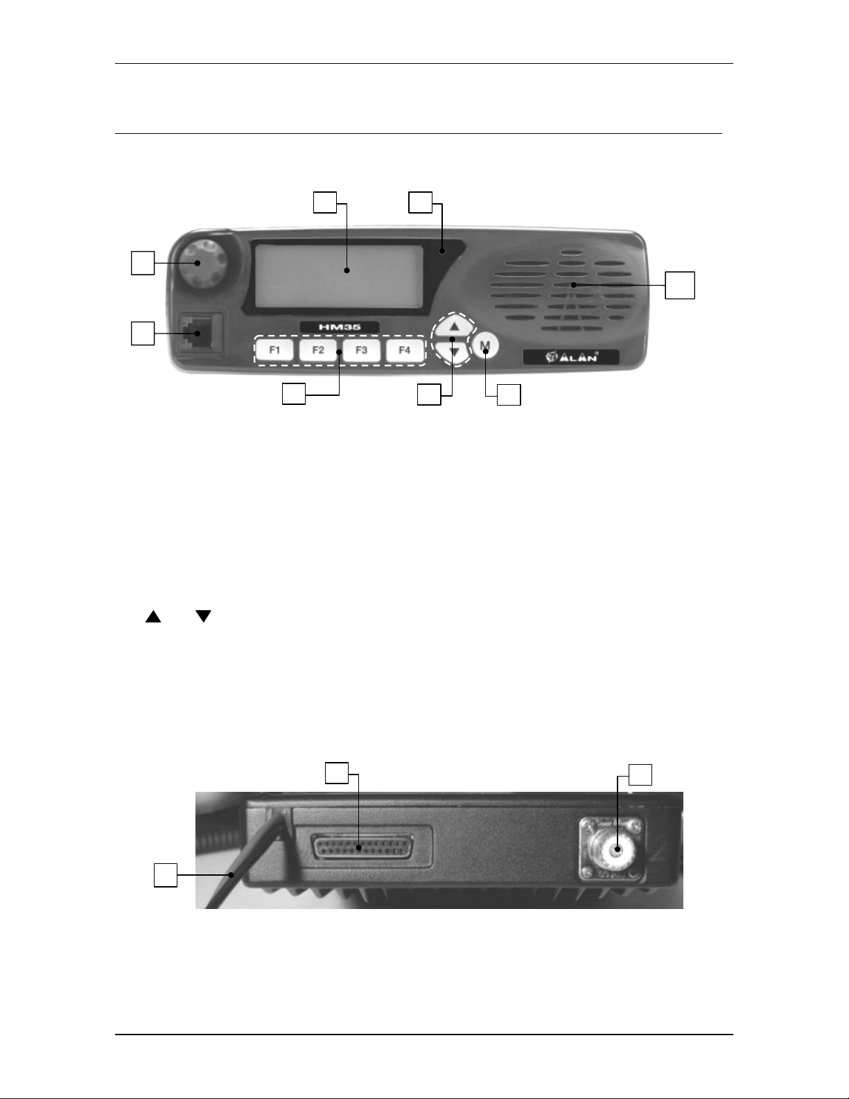
3 PARTS OF THE RADIO AND THEIR USE
3.1 Front panel
1 8
2
3
HM35 Series – User’s Manual
7
4
[1] Display
[2] On/Off-Volume
[3] Microphone
[4]
[5]
[6] Menu/
[7] Internal speaker
[8] Status LED
- constantly displays the operating status of the device and guides the use of various functions
through a series of icons and messages.
knob – used for turning the radio on/off and for adjustment of reception volume.
(MK06/35-K) to the radio.
Programmable function keys
be programmed with fixed selective calls.
The F4/ESC button is also used for exiting a menu (ESC).
(up) / (down) buttons – for channel selection and navigation of the command menu.
socket – this RJ type socket connects the standard hand-held (MK06/35) or keypad microphone
F1, F2, F3
↵ button – for accessing the command menu and confirming the option shown on the display.
.
– is lit with different colors to indicate the radio’s status (transmission, busy channel, etc.)
3.2 Rear panel
10
and
5
E
enable the user to recall commonly used functions or can
SC
F4/
6
11
9
[9] Power cable
negative), for example to the vehicle battery.
Rev. 2.0 on 1 March 2004 Page 8 of 32
– this red/black cable connects to a 13.8 VDC power source (red is positive and black is
Page 9

HM35 Series – User’s Manual
[10] Input/output connector
connections, refer to Par. 13.1.
[11] Antenna
BNC-type connector. For further details, please contact your local vendor.
socket - this SO 239 (UHF) socket is for connecting a suitable antenna. Another option is to use a
– for connection to the external speaker and for activation of external devices. For
Rev. 2.0 on 1 March 2004 Page 9 of 32
Page 10

HM35 Series – User’s Manual
4 CHECKING THE PARTS
4.1.a Package contents
(a) Transceiver
(b) Power cable
(c) Vehicle bracket with screws and knobs for mounting
(d) Mounting piece for micr ophone, with screws
(e) User’s manual (this manual!)
Depending on the model, some parts may already be attached/connected to the device. If any parts are missing or damaged,
contact your vendor as soon as possible.
4.1.b Hand-held microphone
IMPORTANT!
•
Standard microphone MK06/35
• Keypad microphone MK06/35-K – includes standard microphone functions, plus variable selective calling (if activated during
programming).
Both microphones support the monitor function activation when the microphone is removed from its mount. For
further details, refer to par. 5.1.c.
The microphone is ordered separately, and can be one of the following two types:
– microphone for general use, with push-to-talk transmission button (PTT).
Rev. 2.0 on 1 March 2004 Page 10 of 32
Page 11

HM35 Series – User’s Manual
5 ADVICE FOR INSTALLATION
WARNING! Installation of thi s device must be performed by qualifie d persons who are equipped with the proper
tools. The information provided below are designed solely as a complement to the experience held by the
technician, who should assume full responsibility for the installation. Incorrectly installing the transceiver may
seriously damage the devi ce or cause damage to people or prope rty. Follow all of the instructions found in this
chapter and in Chapt. 2.
Installation must be in conformity with the regulations of the vehicle manufacturer. For questions or doubts
regarding this conformity (e.g., holes, the drawing of power, cable passages, etc.), contact your vehicle
manufacturer’s service centre.
As with all electrical devices, this radio requires a periodic laboratory check-up, otherw ise its performance cannot be
guaranteed. For further detail s, contact the administrator of your r adio network or the CTE International technical
office.
5.1 Location/mounting of radio parts
5.1.a Transceiver
Select a location for the radio that is easily accessible to the operator, keeping in mind the security conditions
outlined in Chapt. 2. Use the bracket and screws included in the package to mount the radio.
5.1.b Detachable front panel
In order to reduce obstruction in the driver/passen ger area, the detachable front
panel can be installed on the dashboard, using the proper optional kit available.
For separation and mounting of the front panel, refer to the instru ctions found in
the kit.
5.1.c Hand-held microphone mount
The mount provided (mod. R14053) is to be used as a storage place for the microphone when the radio is inactive.
An option available to the user is the monitor function (hang-up), which is automatically activated when the
microphone is removed from its mount.
For further details regarding the monitor function, refer to par. 6.6.
Microphone installation:
1) Fix the bracket in a position close to the front panel of the radio and near to the radio operator.
2) If you wish to activate the monitor function when removing the microphone from its bracket (hang-up), connect this to the
negative (ground) of the vehicle.
Place the bracket in a location which makes the micro phone cable not taut and avoid that possibl e rocking of the
microphone could cause it hitting the vehicle’s parts or surrounding objects and get damaged. As well, avoid
placing the microphone in a l ocation where sur rounding objects may cause accidental act ivation of the push to talk
(PTT) button and therefore transmission.
Neither the standard (MK06/35) nor the keyboard (MK06/35-K) microphones are supplied with the radio; however, installation
of the mount is the same for both. For further details, refer to par. 4.1.b.
5.2 Installation of the vehicul ar an t enna
Install the antenna on the exterior of the vehicle. Installation must be in conformity with the regulations of the
antenna manufacturer, and according to the instructions included with the antenna. Installation must also be in
conformity with general security and local regulations, as well as with those indicated in Chapt. 2.
Contact your vendor for advice on choosing the best ante nna for your needs. The antenna must be able to irradiate
at least the nominal power of the radio. Once installed and calibrated, the antenna must have a SWR (Standing
Wave Ratio) as low as possible and at below 1:1.5. SWR should be measured with a suitable i nstrument once the
antenna is completely installed in an open space.
Rev. 2.0 on 1 March 2004 Page 11 of 32
Page 12

HM35 Series – User’s Manual
When used in a vehicle, the radio offers optimal performance when the antenna is installed at the center of the roof, in a
vertical position that is free of obstacles.
5.3 Connections
A faulty connection (or connection wi th an unapproved device) can seriously damage the transce iver, as well as
people or objects. For further details, refer to the service manual and/or to the CTE Internati onal technical office.
5.3.a Antenna
After verifying the efficiency of the external antenna, co nnect it to the radio’s
Antenna
using a suitable connector.
5.3.b Power supply
Connect the red/black cable to a 13.8 V
(+/- 10%) power source. The red terminal connects to the positive; the
DC
black is negative and must be groun ded. It is important to ver ify that the power supply line used is able to support
10 A of continuous current.
5.3.c Connection/Disconnection of the microphone
As previously mentioned, two types of microphones are available for purchase separately:
•
Standard microphone MK06/35
• Keypad microphone MK06/35-K – includes standard microphone functions, plus variable selective calling (if activated during
programming).
Standard microphone
To connect the microphone, insert the microphone’s RJ plug into the
– microphone for general use, with push to talk transmission button (PTT) (not supplied).
[3] Microphone
the radio. To disconnect the microphone, hold down the safety clip on the RJ plug and detach it from t he socket
with caution.
Keypad microphone
The keypad microphone MK06/35-K can only be used if the radio has been programmed for its activation, as per the
following instructions. If it has not been programmed, the command described below will not be accessible.
1) Press the menu/↵ button to access the command menu, then press the buttons repeatedly until the
menu is highlighted.
2) Press the menu/↵ again to view the available sub-menus.
3) Press the
will appear beside the sub-menu to indicate that the keypad microphone is active.
4) Exit the sub-menu by pressing the F4/E
screen.
or button repeatedly until the
button, then press it a second time to exit the main menu and return to the standby
SC
Keypad Micr.
sub-menu is highlighted, then press menu/↵ to confirm. A
socket (refer to par. 5.2)
socket on the front panel of
Lcd&Keypad
This procedure should be followed the first time you use your microphone. If you are using the standard microphone, ensure
the
is disabled by following the above procedure.
To connect/disconnect the MK06/35-K keypad microphone, follow the same procedure as described for the standard
microphone.
5.3.d External speaker (optional)
If you possess an external speaker, connect it to the
Input/Output [10]
connector found on the rear panel of the
device, referring to Chapt. 13 and to the instruct ions supplied with the speaker it self. Th e external speaker mus t be
8 Ohm and able to support a minimum of 12 W of power.
The output of the external speaker is grounded. Be careful not to create short-circuits with the body of the vehicle.
The transceiver can be programmed so the external speaker is excluded and only the internal one is used. For further details,
refer to par. 8.4.
Rev. 2.0 on 1 March 2004 Page 12 of 32
Page 13

HM35 Series – User’s Manual
6 BASIC OPERATIONS
IMPORTANT! One or more functions among those described from this point onwards can be rendered
inactive by your radio network administrator, and depending on the radio’s programming. For this reason,
you may find you are not able to access one or more of the functions, or that some functions may differ
from the below descriptions.
Furthermore, it is possible that one or more functions can be activated via the function keys F1, F2, F3 or
F4/ESC, rather than via the normal command menu. In this situation, you w ill see the (abbreviated) function
written directly above the button to w hich the function has been assigned (in other w ords, on the bottom
part of the display).
For further details or when in doubt, contact your vendor/radio network administrator. For information
regarding the use of menu commands and function keys, refer to Chapt. 7.
6.1 Turning HM35 on/off
To turn on the radio, turn the
A welcome message, including the version of software currently installed, will appear on the display.
The radio will automatically carry out a self-test, and will emit a beep to confirm start-up.
To turn off the radio, turn the
On/Off-Volume
On/Off-Volume
knob clockwise until you hear a click.
knob counter-clockwise until you hear a click and the display turns off.
6.2 Volume adjustment
To increase volume, turn the
To decrease volume, turn the knob counter-clockwise.
On/Off-Volume
knob clockwise.
6.3 Channel selection
To select a channel, press the button to scroll through channels upwards or to scroll downwards.
6.4 Reception
There are three reception modes:
•
Open traffic – this mode allows the user to listen to all communication transmitted on the selected channel and volume.
• CTCSS/DCS - if programmed, allows the user to listen only to communication coming from other members of the network with
the same CTCSS/DCS tone/code. For further details, refer to Chapt. 9.
• Selective call - allows the user to send and receive calls from a user or group.
When you receive a valid selective call, the stat us LED will flash orange and an audio signal will alert you to the
incoming call. For further details, refer to Chapt. 9.
CTCSS/DCS and Selective Call may be combined together.
CTCSS/DCS and Selective call allow for sharing of the same frequency on multiple radio networks.
6.5 Squelch adjustment
Your transceiver is equipped with a device able to suppress back ground noise when no signal is being picked up.
You can regulate the threshold of device activation.
1) Press the
2) Press the menu/↵ button once more to v iew th e ava i la ble sub-menus, then
of squelch levels) is highlighted.
Rev. 2.0 on 1 March 2004 Page 13 of 32
↵ button to access the command menu, then use the buttons to highlight the
menu/
until the sub-menu
Radio Param
Squelch
(adjustment
option.
Page 14

HM35 Series – User’s Manual
3) Press menu/↵ to access the sub-menu.
squelch intervention currently being used.
4) Hold down the
5) Now press the
6) Wait for a few seconds to ensure the noise has disappeared stably.
7) Exit the sub-menu by pressing the F4/E
screen.
button until the background noise is continuous.
button to gradually inc rease the level of squelch intervention, stopping as soon as the noise disappears.
SQUELCH
SC button, then press it a second time to exit the main menu and return to the standby
will appear on the display, and a horizontal bar will show the level of
Be careful not to set the squelch level too high: you may not be able to receive weak signals.
6.6 Monitor
The monitor function is mainly used for two purposes:
• To allow for reception of extremely weak signals.
• To temporarily disable the CTCSS/DCS and/or selective calling to allow you to listen to all communications on the tuned
channel, including those outside your network.
Each time the monitor function is activated, will appear on the display.
6.6.a Monitor from the menu
1) Press the menu/↵ button to access the command menu, then use the buttons to highlight
parameters) from the menu.
2) Press menu/↵ to view the sub-menus available and
3) Press
4) Exit the sub-menu by pressing the
screen.
menu/
↵ to insert
beside
Monitor
F4/E
. This indicates that the monitor function is active.
button, then press it a second time to exit the main menu and return to the standby
SC
until the
Monitor
sub-menu is highlighted.
Radio Param
(radio
6.6.b Monitor using the microphone
If the monitor function has been activated (hang-up), you will activate it each time you remove the microphone from
its mount.
6.7 Transmission
1) Remove the microphone from its mount.
2) Ensure the channel is unoccupied (otherwise you will create interference), and verify the status LED is off or flashing orange.
3) Hold down the push to talk (
up in red to confirm that you are transmitting.
4) Speak in a normal voice approximately 5 – 10cm from the microphone.
5) Release the PTT at the end of the call, ensuring the status LED is no longer lit.
6) At the end of the conversation, hang the microphone back up on its mount.
button on the hand-held microphone. The status LED
PTT)
to the right of t he di splay wil l ligh t
[8]
Begin speaking only after having pressed the PTT button and do not release it until you have finished speaking, otherwise all
or part of your message will not be transmitted.
Do not yell! This does not increase the distance of transmission; rather, your words come across as distorted.
Normally, a transceiver will not allow you to send and receive simultaneously, so when you are speaking, others will not be
able to do so. Send your message within a reasonable time period so as not to occupy the channel for very long.
Consult the following paragraphs for information on correct transmission.
6.7.a Time Out Timer (TOT)
The radio can be programmed with an internal TOT (T ime Out Timer), which automatically forces your radio into
reception mode if you have been speaking for too long (time for this is determined in the programming phase). If
this happens, release the transmission button and wait for a few seconds: the transm ission fun cti ons of the radio will
be automatically restored. For further information, contact your vendor or network administrator.
Rev. 2.0 on 1 March 2004 Page 14 of 32
Page 15

HM35 Series – User’s Manual
6.7.b Busy Channel Lock Out (BCLO)
Activation of this function impedes the use of the
button when the channel is busy.
PTT
Depending on the programming, the BCLO can act when it picks up any signal, or when a signal is coming from a
specific CTCSS/DCS signal.
This setting is not available by the end user. For further details, please contact your radio network administrator.
6.7.c Selecting transmission power
Your transceiver can transmit with two different power levels, which are predefined during programming, channel by
channel. The display will always show the power selected, using the following icons:
• - high power
•
- low power
1) Press the
2) Press menu/↵ to view the available sub-menus.
3) Press the
(high power) or Lo (low power).
Hi
4) Press menu/↵ to select the desired power level.
5) Exit the sub-menu by pressing the
screen.
↵ button to access the command menu, then use the
menu/
buttons unt il the sub- menu
button, then press it a second time to exit the main menu and return to the standby
F4/E
SC
buttons to highlight the
is highlighted. The display will show the power level currently selected:
Power
Radio Param
option.
Rev. 2.0 on 1 March 2004 Page 15 of 32
Page 16

HM35 Series – User’s Manual
7 USE OF COMMANDS/OPTIONS
7.1 How to navigate the command menu
Refer to the following diagram.
1) Pressing the menu/↵ button once opens the command menu and displays the five main menus:
Radio Param
2) Press the
3) Press the menu/↵ button to access the menu and view the available sub-menus.
4) Press
5) If necessary, confirm the change once more with the menu/↵ button (e.g. in the case of variable selective calls)
6) Exit the sub-menu by pressing the
screen.
– emission of selective calls
Calls
– performs scanning functions
Scan
Home Chan
LCD&Keypad
Switches
again to scroll through the sub-menus and highlight the desired one:
If you have selected an adjustment (e.g. squelch level), press the
to make changes.
If you have selected an option with two values (e.g. high or low output power), you can switch from one value to another by
pressing the menu/↵ button.
If you have selected an option (activate or deactivate), a
Insert/remove the
If you have selected a selective call, begin transmission by pressing the
– settings/activation of primary radio parameters
– recall of home channel (your most frequently used channel)
– settings for display and keypad
– activates switching for various options
buttons to scroll through main menus and highlight the desired menu.
↵ button to access the sub-menu and use the
menu/
will appear on the display when the option is activated.
symbol by pressing the menu/↵ button.
↵ button.
menu/
button, then press it a second time to exit the main menu and return to the standby
F4/E
SC
menu/↵ to access the command menu
to highight the mai n menu
menu/↵ to access the highlighted menu
to highlight the sub-menu
menu/↵
Chan ge value of
parameter (e.g. Hi or Lo)
insert/remove
(activate/de activate)
Acc ess change functions
to make changes
Send selective call
You can exit the menu/sub-menu at any time, without changing settings, by pressing the F4/ESC button.
The main menu
Home Chan
has a sole purpose of recalling the priority channel; therefore, it does not have a sub-menu.
Rev. 2.0 on 1 March 2004 Page 16 of 32
Page 17

HM35 Series – User’s Manual
7.2 Summary table for the command menu
The following table summarizes the functions of each sub-menu/setting available on your radio. Each submenu/setting will be explained in detail, and its location can be found by referring to the last column of this table.
Main Menu Sub-menu Brief Description Type of command or
Monitor
Squelch
Power
Lock/Dist
Radio Param
Calls
Scan
Home Chan
Lcd&Keypad
TlkAround
Mic.Sens.
Scrambler
Int.Spkr
Off
Call 1
Call 2
User Call
Emergency
Scanning
Scan Esc
Chan Del
Edit List
Rapid recall of most commonly used channel Immediate activation (no sub-menus) 10.2
Contrast
Light
Keypad
Micr.
SUMMARY TABLE FOR COMMAND MENU
Temporary exclusion
Squelch/CTCSS/selective calling
Squelch regulation (suppression of
background noise in standby)
Output power setting
Reception sensitivity attenuator
Allows for single-frequency communication at
repeater output (in case of breakdown)
Regulation of microphone sensitivity
Activation of optional scrambler board (if
installed)
Deactivation of internal speaker
Send fixed selective call - Call 1
Send fixed selective call - Call 2
Send variable user-defined selective call
Send Emergency selective call
Start scanning (searches for signals on
programmed channels)
Temporary pause in scanning Immediate pause 10.1.c
Temporary exclusion of one or more channels
from scanning
Modification of scanning list and of priority
channel
Adjustment of display contrast Bar indicator 8.2
Display backlighting
Activation of microphone with keypad
MK06/35-K
Value available
if monitor is activated
Bar indicator 6.5
(high) / Lo (low)
Hi
(activated) / D (deactivated)
L
if Talk Around is activated
(low) / Hi (high)
Lo
if the scrambler is activated
if the speaker is deactivated
Press menu/↵ to send immediately
Press
Typing variable digits on the keypad
microphone
Press menu/↵ to send immediately
Press menu/↵ to start immediately
Immediate exclusion with menu/↵ –
Chan Del
Modified using the function keys 10.1.d
= activated,
On
and
if MK06/35-K activated
↵ to send immediately
menu/
Auto
= deactivated)
Off
= automatic,
See Par:
6.6
6.7.c
10.4
10.5
8.1
10.6
8.4
9.2.b
9.2.c
9.2.d
10.1.a
10.1.b
8.3
5.3.c
Switches
The main menu
Pad Lock
PA
Aux.Out
Alarm
Home Chan
Lock keypad microphone MK06/35-K
Activation of audio amplifier with external
speaker
Activation of auxiliary output switching
Activation of rear output connector upon
reception of a valid selective call
has a sole purpose of recalling the priority channel; therefore, it does not have a sub-menu.
if keypad is locked
if PA is activated
if contact is activated
if alarm is activated
10.3
10.7
10.8
10.9
During the programming phase, one or more sub-menus may have been disabled and therefore not accessible. Contact your
radio network administrator for further information.
Some functions or sub-menus may have been assigned to the F1, F2, F3, and F4/ESC function keys. Contact your radio
network administrator for further information.
Rev. 2.0 on 1 March 2004 Page 17 of 32
Page 18

7.3 Menu diagram
HM35 Series – User’s Manual
menu/↵
Radio Param Switches Scan Lcd&Keypad Calls
Monitor
Squelch
Power
Loc/Dist
TlkAround
Mic.Sens.
Scrambler
Int.Spkr Off
Ca ll 1
Ca ll 2
Us er Call
Emergency
Scanning
Scan esc
Chan Del
Edit List
7.4 Meanings of display icons
Icon Meaning See par:
Monitor is activated 6.6
Signal received contains correct CTCSS/DSC
Signal received contains a valid selective call
Scanning of active channels 10.1.a
Scanning is temporarily paused 10.1.c
Home channel was called 10.2
Lock on keypad microphone MK06/35-K is activated 10.3
Talk Around function is activated 10.5
Scrambler activated 10.6
PA activated 10.7
Auxiliary output is activated 10.8
External alarm is activated 10.9
High transmission power
Low transmission power
Receiver sensitivity attenuator deactivated (Distant) – maximum sensitivity of receiver
Receiver sensitivity attenuator activated (Local) – reduced sensitivity of receiver
Home chan
Contrast
Light
Keypad Micr.
Pad Lock
PA
Aux.Out
Alarm
9.1
6.7.c
10.4
7.5 Meaning of function key icons.
Each function key is assignable. The table here below summarizes the m eaning of the icons displayed once a
function key is pressed. This section not found in PDF version.
Rev. 2.0 on 1 March 2004 Page 18 of 32
Icon Description
Sends variable user-defined selective call
mon Monitor is activated
Alarm is activated
scan Starts scan
Interrupts scan
Cancels a channel from the scan list
Shows the scan list
Activates PA function (public address)
Activates talk around function
Sends fixed selective call - Call 1
Sends fixed selective call - Call 2
Page 19

Activates scrambler
Locks the keypad of the keypad mike (MK03535-K)
sql Activates the regulation of squelch level
Adjusts contrast
Adjusts brightness
Activates auxiliary output
Sends a call to the priority channel
l/d Activate/ deactivates local/distance mode
Adjusts microphone sensitivity
pow Selects high/low power
Key not assigned
Deletes a channel from the scan list
Inserts a channel in the scan list
Sends an emergency call
Activates the MK0635-K mike
Displays the predefined messages
Agenda
HM35 Series – User’s Manual
Rev. 2.0 on 1 March 2004 Page 19 of 32
Page 20

HM35 Series – User’s Manual
8 CUSTOMIZATION
This section describes the settings that regulate various paramet ers, depending on environment and specific use of
the radio; for example, display contrast, backlighting, etc.
8.1 Adjustment of microphone sensitivity
Normally, the sensitivity of the microphone allows the user to speak at a distance of up t o 10 centimeters from the
microphone. However, if the surroundings or the vehicle in which you are working is particularly noisy, you can
reduce the sensitivity of the microphone so as to avoid trans mitting your surrounding noises to others. When the
sensitivity is decreased, you need to speak closer to the microphone and/or with a louder voice, but your message
will still be heard clearly. To adjust the microphone sensitivity:
1) Press the menu/↵ button to access the command menu, then use the buttons to highlight the
2) Press menu/↵ to view the sub-menus available.
3) Press the
(low sensitivity) or
4) Press menu/↵ if you wish to change the setting from
5) Exit the sub-menu by pressing the F4/E
screen.
buttons until the
(high).
Hi
Mic. Sens.
SC
(microphone sensitivity) sub-menu is highlighted. The display will show Lo
to Hi or vice-versa.
Lo
button, then press it a second time to exit the main menu and return to the standby
Radio Param
option.
8.2 Adjustment of display contrast
Depending on your ambient light and temperature, you may wish to change the display contrast for a better view of
the screen. To change the contrast:
1) Press the
2) Press menu/↵ to view the sub-menus available.
3) Press the
to enter the setting.
contrast currently selected.
4) Press the or buttons repeatedly until the desired contrast level appears.
5) Press menu/↵ to confirm the contrast level setting.
6) Exit the sub-menu by pressing the
screen.
↵ button to access the command menu, then use the buttons to highlight the
menu/
buttons until the
CONTRAST
Contrast
will appear on the display, and will show a series of horizontal bars proportional to the
F4/E
(adjustment of display contrast) sub-menu is highlighted, then press menu/↵
button, then press it a second time to exit the main menu and return to the standby
SC
Lcd&Keypad
option.
8.3 Backlight adjustment
This command is for setting display and keypad backlight adjustment and auto-adjustment as follows:
1) Press the menu/↵ button to access the command menu, then use the buttons to highlight the
2) Press
3) Press the
4) Press the menu/↵ button repeatedly until the desired setting is selected.
5) Exit the sub-menu by pressing the F4/E
screen.
↵ to view the sub-menus available.
menu/
buttons until the
– backlight always activated
On
– backlight is automatic - will activate as soon as you use any command, and will deactivate approximately 20
Auto
seconds after the last command is given.
– backlight deactivated
Off
(backlighting) sub-menu is highlighted. The display will show:
Light
SC button, then press it a second time to exit the main menu and return to the standby
Lcd&Keypad
option.
Rev. 2.0 on 1 March 2004 Page 20 of 32
Page 21

HM35 Series – User’s Manual
8.4 Exclusion of internal speaker
If your transceiver is connected to a n (optional) external speaker, you may wish under some conditions to use only
the external speaker, and exclude the internal one. To do this:
1) Press the menu/↵ button to access the command menu, then use the buttons to highlight the
option.
2) Press
3) Press the
4) Press menu/↵ to insert the
5) Exit the sub-menu by pressing the F4/E
screen
↵ to view the sub-menus available.
menu/
buttons until the
symbol beside the appropriate option. (In other words, so the internal speaker is deactivated.)
Int.Spkr Off
SC button, then press it a second time to exit the main menu and return to the standby
(deactivation of internal speaker) sub-menu is highlighted.
Radio Param
.
To reactivate the internal speaker, follow the above procedure and, at Step 3, press menu/
↵
to delete the symbol.
Do not disconnect the external speaker when the internal one is deactivated. You may damage the radio.
Rev. 2.0 on 1 March 2004 Page 21 of 32
Page 22

HM35 Series – User’s Manual
9 USE WITH CTCSS/DCS AND/OR SELECTIVE CALLS
9.1 Reception
In this operating mode, your radio is programmed so that the audio is activated only when receiving a correct
CTCSS/DCS and/or selective call signal.
The audio will thus remain silent until you receive a correct CTCSS tone, a correct DCS code, and/or a valid
selective call.
• If a correct CTCSS/DCS signal is received, the status LED will light up in orange for the duration of signal reception, and the
icon will appear on the display.
If a valid selective calling signal is received, the status LED will flash orange and the icon will appear on the display.
•
If a signal is received but does not contain the correc t tone/code, t he audio will remain deactivated and the LED will
appear green.
Depending on the radio’s programming, it may be possible to temporarily deactivate CTCSS/DCS and Selective call to
monitor radio traffic (monitor function). For further details, refer to par. 6.6.
9.2 Transmission
9.2.a CTCSS/DCS Transmission
If your transceiver has been programmed to transmit a CT CSS tone or a DCS code, you don’t have to do anything.
The CTCSS tone or DCS code are automatically sent each time you transmit (the device will not show this status).
9.2.b Sending a selective call
Depending on the programming, your transceiver may be able to send up to four selective calls:
Call 1 – first selective call (fixed)
Call 2 – second selective call (fixed)
User – variable selective call; the variable digits can be keyed into the MK06/35-K keypad microphone (refer to. par.
4.1.b).
Emergency
phase).
Rapid send of selective calls
Your transceiver can be programmed to send certain selec tive c alls us ing one or more of the F1, F2, F3 and
function keys or using the command menu. Also, the
contact on the rear
To emit a fixed selective call using the function keys:
Ensure the channel is unoccupied by checking that the status LED is off (or flashing orange).
1)
2) Press the F1, F2, F3 or F4/E
status LED will be lit in red, and the display will simultaneously show the selective address corresponding to the button
pressed.
When you follow the operation outlined in step 2, the device will automatically go into transmission mode (status LED lit in
red); therefore, you do not need to press the PTT transmission button on the hand-held microphone.
Sending a fixed selective call from the menu
1)
Ensure the channel is unoccupied by checking that the status LED is off or flashing orange.
2) Press the menu/↵ button to access the command menu, then use the
3) Press
menu/
Call1
Call2
User Call
Emergency
– selective call for emergencies (special call sent repeatedly, and defined during the programming
selective call can be activated via a suitable
buttons to highlight the
Calls
option.
Input/Output
↵ to view the selective calls available:
– fixed call 1
– fixed call 2
(variable selective call)
(emergency call)
socket. For further details, refer to Chapt. 13.
key that corresponds to the call you wish to send. The call will be sent automatically, the
SC
Emergency
F4/E
SC
Rev. 2.0 on 1 March 2004 Page 22 of 32
Page 23

HM35 Series – User’s Manual
4) Press the buttons until
automatically return to the standby screen.
Call 1
or
Call 2
is highlighted, then press menu/↵ to make the call. The device will
9.2.c Sending a variable selective call
The selective variable is only available through the keypad microphone (mod. MK06/35-K).
If the channel has been programmed to emit a selectiv e variable, a * symbol will appear on the bottom left of the
display, followed by the predefined variable digits. A selective variable can be sent using two methods:
Emission via microphone
Key in the variable digits using the microphone keypad, then press the
Emission via the menu
1) Key in the variable digits using the microphone keypad.
2) Follow steps 2 and 3 from the par. “Sending a fixed selective call from the menu”.
3) Press the
buttons until
User Call
is highlighted, then press menu/↵ to make the call.
button on the microphone.
*CALL
9.2.d Sending an emergency selective call
This is a special call that is sent repeatedly in cycles on a predefined channel based on the radio’s programming.
Use this emergency call only if you find yourself in a real condition of necessity which requires assistance. Speak to
your radio network administra tor about its use.
Your radio can be programmed to deactivate all other commands when it is making an emergency call.
An emergency call can also be sent using the Input/Output connector.
Emission via microphone
Hold down the
Emission via the menu
1) Follow steps 1 and 3 from par. “Sending a fixed selective call from the menu”.
2) Press the
button on the keypad microphone until the emergency selective call is emitted, then release.
EMG
3
buttons until
Emergency
(emergency call) is highlighted, then press menu/↵ to make the call.
Rev. 2.0 on 1 March 2004 Page 23 of 32
Page 24

HM35 Series – User’s Manual
10 ADVANCED FUNCTIONS
10.1 Channel scanning
This function is particularly helpful when multiple channels have been programmed. It allows you to follow radio
traffic, as well as to respond to calls from different channels. When the radio picks up a valid signal during
scanning, it pauses on that channel and communicati on is heard on the speaker. When the signal ends, s canning
begins again automatically.
If CTCSS/DCS or selective calls have been previously programmed, the device can be programmed to paus e only
at incoming signals containing the appropriate signals.
10.1.a Activation of scanning
1) Press the menu/↵ button to access the command menu, then use the buttons to highlight the
2) Press menu/↵ to view the available sub-menus.
3) Press the
4) Press menu/↵ to insert the
5) Exit the sub-menu by pressing the
screen. The
buttons until the
icon will appear on the display.
Scanning
symbol.
F4/E
SC
sub-menu is highlighted.
button, then press it a second time to exit the main menu and return to the standby
During scanning, the and buttons will not change the operating channel.
Scan
option.
If you try to activate scanning using an empty scanning list, an error sound will be emitted and scanning will not start.
Obviously, the list of scanning channels must include at least two channels.
If you press the PTT transmission button during channel scanning, the radio will pause on a predetermined channel, chosen
during the programming phase (this will be the priority channel or another predefined one), and will begin transmission. When
you release the PTT, the scanning will begin again automatically.
To stop the scanning, repeat the above procedure (at step 4, remove the ).
10.1.b Temporary exclusion of channels from scanning
You can temporarily exclude channels that are of no interest from the scanning list as follows:
1) If scanning pauses frequently on communications that are of no interest, press the
then press the
2) Press menu/↵ again to view the available sub-menus.
3) Select Chan Del (temporary removal of channel from scanning) using the
channel will be temporarily removed from the scanning list.
The channels excluded from scanning will remain excluded until the device is turned off and on; after this is done, they are
again reinserted into the list.
or button until the
menu is highlighted on the display.
Scan
keys, then press the menu/↵ button. The
10.1.c Temporary pause in scanning
1) When scanning temporarily pauses on a communication of interest, press the
then press the
2) Press menu/↵ again to view the available sub-menus.
3) Press the
Scanning will stop on the channel currently selected, and the standby icon
buttons until the
buttons until the
Scan Esc
menu is highlighted on the display.
Scan
(temporary exit from scanning) sub-menu is highlighted and press
menu/
will appear on the display.
↵ to access the command menu,
menu/
↵ button to access the command menu,
menu/
↵.
To restart scanning, repeat the procedure outlined above.
If this command is used frequently, we suggest you program it into one of the function keys. Contact your radio network
administrator for further details.
Rev. 2.0 on 1 March 2004 Page 24 of 32
Page 25

HM35 Series – User’s Manual
10.1.d Changing the channel scanning list
You can use this function to create a pers onalized scanni ng list and to set a priority channel that is diff erent fr om the
pre-programmed one.
1) Ensure that scanning is not activated.
2) Press the menu/↵ button to access the command menu, then use the
3) Press menu/↵ to view the available sub-menus.
4) Press the
appear. Above the four function buttons, the following should also appear on the display:
5) Depending on what you would like to do, press the corresponding function button.
F2 Adding new channels to the list
1) Press the F2 (
2) Press the
3) Press the
4) Exit the sub-menu by pressing the F4/E
screen.
F3 Deleting channels from the list
1) Press the
2) Press the F3 (
3) Exit the sub-menu by pressing the F4/E
screen.
F1 Changing the priority channel
1) Remove the current priority channel from the scanning list, following the procedure outlined above.
2) Remove the new channel that you wish to assign as the priority channel from the scanning list.
3) Press the F1 (
4) Press the
5) Press the menu/↵ button twice to memorize the new priority channel and exit the scanning list.
6) If necessary, reinsert the old priority channel in the scanning list, following the procedure outlined above.
7) Exit the sub-menu by pressing the F4/E
screen.
buttons until the
padd
F1 F2 F3 F4/ESC
chadd
buttons until the channel you desire appears on the screen.
↵ button to memorize the channel in the scanning list.
menu/
buttons repeatedly until the channel you wish to delete from the scanning list has been selected.
chdel
padd
buttons until the channel you desire as priority appears on the screen.
chadd
) function key. You will see the first channel that is not inserted in the scanning list.
) function key to remove the channel from the scanning list.
) function key. You will see the first channel that is not inserted into the scanning list.
Edit List
SC
SC
SC
sub-menu is highlighted. The first channel added to the scanning list wil l
chdel
button, then press it a second time to exit the main menu and return to the standby
button, then press it a second time to exit the main menu and return to the standby
button, then press it a second time to exit the main menu and return to the standby
esc
buttons to highlight the
Scan
option.
10.2 Rapid recall of home channel
This function allows you to quickly recall the channel most frequently used (home channel).
1) Press the
2) Press menu/↵ again to confirm the channel.
↵ button to access the command menu, then use the buttons to highlight the
menu/
will appear on the display.
Home Chan
option.
10.3 Locking microphone’s keypad
If you use the MK06/35-K keypad microphone, you can lock its keypad in order to avoid sending accidental
commands during use.
1) Press the
2) Press menu/↵ again to view the available sub-menus.
3) Press the
4) Press
5) Exit the sub-menu by pressing the F4/E
menu/
screen. The
Rev. 2.0 on 1 March 2004 Page 25 of 32
↵ button to access the command menu, then use the keys to highlight the
menu/
buttons repeatedly until the
↵ to insert an
icon will appear on the display.
. The device’s keypad will be deactivated.
SC
Keypad Lock
button, then press it a second time to exit the main menu and return to the standby
sub-menu is highlighted.
Lcd&Keypad
option.
Page 26

HM35 Series – User’s Manual
To reactivate the keypad, follow the procedure outlined above (at step 4, remove the ).
When the keypad is locked, the On/Off-Volume knob, the microphone PTT, and some function keys will still remain active
(depending on the device’s programming).
10.4 Signal reception attenuator
If you are in an area where radio signals are too strong (e.g., near a high-powered repeater or transmitter), you may
find that these signals saturate your receiver, reducing p erformance. To avoid this situation, you can temporarily
insert an internal signal attenuator as follows:
1) Press the menu/↵ button to access the command menu, then use the buttons to highlight the
2) Press menu/↵ to view the available sub-menus.
3) Press the
(distant).
4) Press menu/↵ to select
5) Exit the sub-menu by pressing the F4/E
screen.
buttons repeatedly until the
(local).
L
Loc/Dist
button, then press it a second time to exit the main menu and return to the standby
SC
(local/distant) sub-menu is highlighted. To its left, you will see a D
Radio Param
option.
In stand-by, the display will always show the current setting with the (distant = attenuator deactivated) or (loc al =
attenuator activated) icon.
As soon as conditions retur n to normal (e.g., you have moved to a n area where signals are not as st rong), do not
forget to deactivate the attenator, otherwise you will not be able to receive weak signals.
To deactivate the attenuator, follow the procedure outlined above, selecting D at step 4.
10.5 Talk Around
If you are operating with a repeater and it breaks down, you can use the Talk Around function to communicate with
nearby stations by bypassing the repeater. To activate this function:
1) Select a semi-duplex channel (otherwise the Talk Around function cannot be activated)
2) Press the
3) Press menu/↵ to view the available sub-menus.
4) Press the
5) Press menu/↵ to insert the
the device is in standby.
6) Exit the sub-menu by pressing the
screen.
↵ button to access the command menu, then use the
menu/
buttons repeatedly until the
symbol. The Talk Around function is activated and the icon will appear on the display when
F4/E
TlkAround
button, then press it a second time to exit the main menu and return to the standby
SC
buttons to highlight the
sub-menu is highlighted.
Radio Param
option.
Do not forget to deactivate the Talk Around function when you have finishe d speaking with your receiving party,
otherwise you will not be able to use the repeater when it has been fixed.
10.6 Confidential transmission (optional scrambler board)
Your transceiver may be equipped with an optional internal scrambler board. This is a device that makes your
communication unintelligible by normal radio receivers/transceiv ers, but perfectly clear to other members of your
radio network, who will be equipped with a compatible scrambler board.
To activate the scrambler:
1) Ensure your receiving party has activated their scrambler.
2) Press the menu/↵ button to access the commend menu, then use the
3) Press
4) Press the
↵ to view the available sub-menus.
menu/
buttons repeatedly until the
Scrambler
sub-menu is highlighted.
buttons to highlight the
Radio Param
option.
5) Press
the device is in standby.
menu/
↵ to insert the
symbol. The scrambler function is activated, and the icon will appear on the display when
Rev. 2.0 on 1 March 2004 Page 26 of 32
Page 27

HM35 Series – User’s Manual
6) Exit the sub-menu by pressing the F4/ESC button, then press it a second time to exit the main menu and return to the standby
screen.
To deactivate the scrambler:
1) Ensure your receiving party has also deactivated their scrambler.
2) Follow the procedures outlined above. At step 5, remove the
symbol.
10.7 Audio amplifier (PA function)
It is possible to use the transceiver’s audio amplif ier to drive an external speaker and amplify your voice. This
provides you with a sort of “mobile megaphone”, which can be used for special operations. To activate this function:
1) Press the menu/↵ button to access the command menu, then use the buttons to highlight the
2) Press
3) Press the
↵ to view the available sub-menus.
menu/
buttons repeatedly until the PA sub-menu is highlighted.
Switches
option.
4) Press menu/↵ to insert the
5) Exit the sub-menu by pressing the
screen.
At this point, each time you press the
symbol. The audio amplifier will be activated, and the icon will appear on the display.
button, then press it a second time to exit the main menu and return to the standby
SC
F4/E
transmission button, instead of transmitt ing, your voice transmission will
PTT
be heard on the external speaker.
To reactivate normal radio functions, repeat the above procedure, removing the
Once you have finished using the PA, do not forget to reactivate your radio’s normal functions.
symbol in step 4.
A faulty connection to the external speaker may seriously damage the trans ceiver.
10.8 Auxiliary output
The rear
Input/Output
turn your device on/off. To activate this function:
1) Press the menu/↵ button to access the command menu, then use the buttons to highlight the
2) Press menu/↵ to view the available sub-menus.
3) Press the
4) Press menu/↵ to insert the
the device is in standby.
5) Exit the sub-menu by pressing the
screen.
To reactivate normal radio functions, follow the procedure outlined above.
socket of the radio can control external devices that are activated/deactivated each t ime you
buttons repeatedly until the
symbol. The auxiliary output will be activated, and the icon will appear on the display when
button, then press it a second time to exit the main menu and return to the standby
SC
F4/E
Aux.Out
sub-menu is highlighted.
Switches
option.
A faulty connection to the Input/Output socket may seriously damage the transceiver.
10.9 External alarm
You can program your radio so that, each time you receive a valid selective call, external devices are activ ated (e. g.,
an acoustic alarm to advise you of an incoming call if you are away from your vehicle) using a suitable contact with
the rear
1) Press the menu/↵ button to access the command menu, then use the buttons to highlight the
2) Press menu/↵ to view the available sub-menus.
3) Press the
4) Press menu/↵ to insert the
Input/Output
the device is in standby.
Rev. 2.0 on 1 March 2004 Page 27 of 32
socket on the radio. To activate this function:
buttons repeatedly until the
symbol. The auxiliary output will be activated, and the icon will appear on the display when
Alarm
(auxiliary output) sub-menu is highlighted.
Switches
option.
Page 28

HM35 Series – User’s Manual
5) Exit the sub-menu by pressing the F4/ESC button, then press it a second time to exit the main menu and return to the standby
screen.
A faulty connection to the Input/Output socket may seriously damage the transceiver.
Rev. 2.0 on 1 March 2004 Page 28 of 32
Page 29

HM35 Series – User’s Manual
11 CLEANING AND MAINTENANCE
11.1 Maintenance of the radio
Aside from the normal cleaning and connection efficiency check, your radio does not require any particular
maintenance.
As with all electrica l devices, your radio requir es periodic laboratory testing , otherwise its performance cannot be
guaranteed. For further details, contact your radio network administrator or CTE International technical office.
11.1.a Cleaning the radio
Carefully polish the radio using a soft, clean cloth that does not have loose fibers. If the radio is very dirty, slightly
dampen the cloth in a solution of 90% water and 10% neutral soap.
Do not use liquid detergents, sprays, alcohol, solvents, or abrasives.
11.1.b Connectors
During cleaning, be careful not to damage, dampen, or scratch the connectors.
Attach your radio connectors only to approved accessories. For further details, contact your authori zed dealer.
Rev. 2.0 on 1 March 2004 Page 29 of 32
Page 30

HM35 Series – User’s Manual
12 OPTIONAL ACCESSORIES
Optional accessories can be used to expand the range of functi ons available with your radio. We are constantly
developing new options for you, and are pleased to list below the accessories we currently offer:
• MK06/35 standard microphone – microphone for general use, with PTT transmission button.
•
MK06/35-K keypad microphone
calls (if activated during the programming phase).
• Microphone with base – microphone with stand-alone base
• 220VAC/13.8Vdc stabilized power s upply – for using the transceiver as a base station (properly connected to an external
antenna).
• Kit for detachable front panel – includes a connection cable from the front panel to the radio body, as well as the bracket and
hardware to mount the front panel.
– along with the standard microphone functions, it allows the user to make variable selective
Rev. 2.0 on 1 March 2004 Page 30 of 32
Page 31

13 CONNECTIONS
13.1 Input/Output rear connector
HM35 Series – User’s Manual
The following table outlines the connections from the rear
N. Signal name Notes
AUX OUT
1
- Not connected
2
EXT SPEAKER
3
FLAT UN-SQ RX AUDIO
4
DE-EMPH-SQ RX AUDIO
5
RX MUTE INPUT
6
TX AF IN
7
PTT OUTPUT
8
EXTERNAL PTT
9
SELCAL VALID
10
RSSI LEVEL
11
CDS SIGNAL
12
HANG UP
13
GND Grounded
14
GND Grounded
15
EXT SPEAKER +
16
Spare 2 Additional contact for special use
17
Spare 1 Additional contact for special use
18
Output 12V 100 mA max.
19
Backlight control input
20
INPUT/OUTPUT 2
21
INPUT/OUTPUT 1
22
External alarm input
23
Emergency switch - input
24
Ignition sense input
25
Input/Output
(DB25) connector:
Faulty connections may seriously damage y our radio. Before connecting any device, consult the service manual
and your CTE International technical office.
13
25
1
14
Rev. 2.0 on 1 March 2004 Page 31 of 32
Page 32

14 ALPHABETICAL INDEX
Advanced functions
Auxiliary output........................................................... 25
Channel scanning.......................................................22
Keypad lock................................................................ 23
PA audio amplifier.......................................................25
Rx attenuator.............................................................. 24
Scrambler.................................................................... 24
Selective call switching...............................................25
Talk Around................................................................. 24
Assistance...............................................................6
Basic operations ...................................................12
Channel selection....................................................... 12
Monitor........................................................................ 13
Squelch adjustment.................................................... 12
Transmission............................................................... 13
Turning radio on/off.....................................................12
Volume adjustment.....................................................12
Channel scanning
Activation/deactivation................................................22
Changing priority channel...........................................23
Changing scanning list................................................23
General.......................................................................22
Temporary exclusion................................................... 22
Temporary pause........................................................22
Channel selection .................................................12
Checking the parts..................................................9
Connections
Rear Input/Output connector....................................... 29
Conventions & Symbols..........................................5
CTCSS/DCS
General.......................................................................12
Monitor........................................................................ 13
Transmission............................................................... 20
Customization
Backlight adjustment...................................................18
Display contrast adjustment........................................18
Excluding internal speaker..........................................19
Microphone sensitivity......................................... ..... ...18
Icons
HM35 Series – User’s Manual
Meanings.....................................................................17
Maintenance
Cleaning the radio........................................................27
Connectors ..................................................................27
Menu
Diagram.......................................................................17
How to navigate...........................................................15
Summary table.............................................................16
Microphone sensitivity .......................................... 18
Monitor.................................................................13
Parts and their use................................................. 7
RX attenuator................................... ....................24
Scrambler............................................................. 24
Security..................................................................5
Selective call
Emergency...................................................................21
General........................................................................12
Monitor.........................................................................13
Transmission ...............................................................20
Variable........................................................................21
Set-up
Checking the parts.........................................................9
Location/mounting of radio parts.................................10
Talk Around.......................................................... 24
Technical speci fications................ ........................30
Time Out Timer (TOT).......................................... 13
Transmission
How to properly transmit..............................................13
Lock-out with busy channel.........................................14
Power selection ...........................................................14
TX Time Out timer .......................................................13
Turning HM35 on/off............................................. 12
Volume adjustment............................................... 12
Warnings................................................................ 5
Rev. 2.0 on 1 March 2004 Page 32 of 32
 Loading...