

Page 1
Midland 248XL
” GUIDA ALL‘USO
” INSTRUCTION GUIDE
” BEDIENUNGSANLEITUNG
” MANUAL DE INSTRUCCIONES
” GUIDE D'UTILISATION
” MANUAL DE INSTRUÇÕES
” Ο∆ΗΓΙΕΣ ΧΡΗΣΗΣ
” INSTRUKCJA OBSLUGI
Page 2

Italia - Restrizioni all’uso - In conformità al Piano Nazionale di ripartizione delle Frequenze, pubblicato sulla G.U. n. 169 -Supplemento Ordinario 146 - del 20 luglio 2002 - nota 49G -, per lo standard I in AM occorre utilizzare un sistema radiante che abbia il guadagno complessivo non superiore a -6 dB (es.: con antenna
PC8 con cavo originale).
Italy - Restrictions on the use - According to the Italian Frequency Allocation Table, issued on the G.U. No. 169 - Supplement 146 - of 20th July 2002 - note 49G,
the standard I in AM modulation needs a radiating system with a gain not higher than -6dB, such as, for example, with the antenna “PC8” with original cable.
Italie - Restrictions à l’usage - Conformément au Tableau National de répartition des bandes de fréquences publié sur la G.U. n. 169, Supplément 146 - du 20
Juillet 2002 – note 49G -, pour le standard I in modulation AM il faut utiliser un système radiante avec un gain pas supérieur à –6dB (par exemple, avec l’antenne PC8 avec câble original).
Italien - Nutzungshinweis - Entsprechend der Italienischen Frequenzverteilungstabelle, herausgegeben in G.U,. No. 169, Anhang 146 vom 20. Juli 2002, Note
49 G, darf bei Standard I in AM Modulation nur ein Antennensystem von nicht mehr als -6dB Gewinn benutzt werden, wie z.B. der Antennentyp “ PG 8 “ mit
Originalkabel
Italia - Restricciones al uso - De acuerdo con el Piano Nazionale di Ripartizione delle Frequenze, publicado en la G.U. n° 169 - Supplemento Ordinario 146 - del
20 de julio de 2002 - nota 49G - , por el estándar I en la modalidad AM se deberá utilizar un sistema radiante que tenga una ganancia conjunta no superior a
-6dB (es.: con antena “PC8” con cable original)
Page 3

INDICE
Introduzione ............................................................................................................................2
Descrizione comandi ...........................................................................................................3
Installazione ............................................................................................................................7
Collegamento elettrico .......................................................................................................7
Installazione dell’antenna ..................................................................................................7
Uso di Midland 248XL .........................................................................................................8
Selezione bande di frequenza ..........................................................................................8
Tabella bande di frequenza ...............................................................................................8
Caratteristiche tecniche ......................................................................................................9
Midland 248XL è un ricetrasmettitore veicolare la cui caratteristica principale
è la possibilità di selezionare qualsiasi banda CB europea tramite una semplice ed immediata procedura.
Midland 248XL è inoltre dotato dei dispositivi “ESP2” e “NOISE BLANKER”
(soppressori dinamici dei disturbi) che permettono di ridurre notevolmente
i disturbi audio (fino al 95%) facilitando l’ascolto anche quando il segnale è
disturbato.
L’ampio display multifunzionale permette la visualizzazione del numero del
canale in uso o della frequenza corrispondente ed è retroilluminato per una
comoda visualizzazione notturna.
Midland 248XL è dotato inoltre uno strumento S-Meter analogico per una
comoda visualizzazione della potenza trasmessa e del segnale ricevuto.
L’apparato viene consegnato secondo la banda “EC“ 40CH FM 4W.
I
1
Page 4
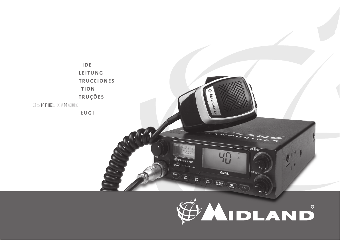
DESCRIZIONE COMANDI
2
8 9 10 11 12 13 14
1
CH
MIC
1. Selettore canali: permette la selezione manuale dei canali.
2. Presa microfono: inserire lo spinotto microfonico in questa presa.
3. Indicatore: questo strumento indica l’intensità dei segnali in ricezione e la
potenza di uscita RF del trasmettitore.
4. Display retroilluminato multifunzione
a. Numero canali selezionati (da 1 a 40) o frequenza corrispondente.
b. Attivazione tasto FUNC.
c. ESP: attivazione soppressore dinamico dei disturbi.
d. DW: funzione DUAL WATCH attivata
CB/PA
FUNC
01
0
3 4567
3
5
3
2
POWER
TX RX AM FM
M1
EMG
b
30
9
7
10
5
®
F
M3
M2
SCAN
DW
a
ecfdg
j
EMGDWESP LOCK SCANLOW
M4/LCR
AM/FM
LOCK
VOL
SQ
17
18
MIC
RF
16
N.K.M5
15
i
h
e. EMG: indicatore attivazione canale 9 / 19 o canale in uso
f. LOCK: indicatore funzione blocco tasti e selettori attivata
g. SCAN: indicatore funzione SCAN attivata
h. M1-M2-M3-M4-M5: indicatori memorie canali .
i. Indica la banda di frequenza selezionata.
j. Viene visualizzato quando la radio trasmette in bassa potenza (condi-
zione che si verifica solo per determinate bande di frequenza – vedi
tabella bande)
5. Indicatore “AM/FM”
Indica il modo operativo. FM: LED rosso; AM: LED verde.
6. Indicatore “RX/TX”
Indicatore di ricezione / trasmissione. Posizione RX: LED verde; posizione
TX: LED rosso.
7. Selettore “CB - PA”
Posizione “CB” : in questa posizione, l’apparato é attivo come ricetrasmetti-
tore.
Posizione “PA ”: questo modo di funzionamento é possibile solo se viene
collegato un altoparlante alla presa PA sul retro (scritta “PA” visualizzata
sul display). In questo caso, il comando “MIC” viene usato come controllo
dell’amplificazione.
8. Tasto FUNC
Questo tasto permette, a scelta dell’utente, di:
• visualizzare il canale o la frequenza operativa premendo “FUNC” per circa 3
secondi.
• attivare le seconde funzioni dei tasti “M” (M1/M5).
M1 / M2 / M3 / M4 / M5:
La radio ha la possibilità di memorizzare e di richiamare all’occorrenza 5
canali a piacimento precedentemente memorizzati. Per memorizzarne
uno, procedere come segue:
A) Selezionare il canale che si desidera memorizzare tramite il selettore canali
o i tasti “UP/DN” sul microfono;
B) Premere il tasto “FUNC”: il display mostrerà una “F”;
C) Tenere premuto per circa tre secondi il tasto “M1/EMG”: la radio emetterà
un “BIP” e il display mostrerà la scritta “M1”.
Per memorizzare altri canali ripetere i punti A e B e selezionare una diversa
memoria.
Per richiamare un canale precedentemente memorizzato premere il tasto
“FUNC” e di seguito il tasto della memoria desiderata.
2
Page 5

I tasti di memorizzazione canali hanno una doppia funzione; qui di seguito
sono descritte le 2 modalità di funzionamento.
9. Pulsante “M1 - EMG”
Permette di memorizzare la memoria numero 1 e di richiamare i canali
di emergenza. La pressione del tasto “M1/EMG” seleziona ciclicamente il
canale 9, 19 ed il canale in uso.
10. Pulsante “M2 - DW”
Permette la memorizzazione della memoria numero 2 e l’attivazione della
funzione DUAL WATCH, che consiste nel rimanere sintonizzati contemporaneamente su due canali a scelta dell’utente.
Con tale funzione si monitorizzerà ciclicamente un secondo canale. In
presenza di un segnale sul secondo canale, la conversazione sul canale
prescelto si interromperà e il ricevitore commuterà automaticamente sul
secondo canale. Il monitoraggio riprenderà dopo 5 secondi dal cessare del
segnale.
Per attivare questa funzione, operare come segue:
- Selezionare il canale desiderato mediante il selettore canali o i tasti
“UP/DN” sul microfono;
- Premere il tasto “DW” per circa 3 secondi: la radio emetterà un “BIP” e
sul display lampeggerà la scritta “DW”.
- Selezionare il secondo canale desiderato tramite il selettore canali o i
tasti “UP/DN” sul microfono;
- Premere nuovamente il tasto “DW” per 3 secondi circa: la radio emetterà un ‘BIP’, il display mostrerà la scritta “DW” permanente e visualizzerà
alternativamente i due canali selezionati.
11. Pulsante “M3 - SCAN”
Tramite questo tasto, si memorizza la memoria numero 3 e si attiva la fun-
zione “SCAN” (ricerca automatica di un canale occupato).
Per attivare questa funzione, operare come segue:
- selezionare un canale libero e ruotare la manopola dello squelch in
senso orario in modo che il rumore di fondo scompaia;
- premere il tasto “M3/SCAN”: il display mostrerà la scritta “SCAN” ed il
ricetrasmettitore scansionerà automaticamente e ripetutamente tutti
i canali fino a quando non troverà un canale in uso.
La funzione “SCAN” può essere annullata in tre modi: premendo il tasto
PTT, ruotando il selettore canali o premendo un qualsiasi tasto.
12. Pulsante “M4/LCR - AM/FM”
Questo tasto, permette la memorizzazione della memoria numero 4 e la
selezione del modo operativo (AM/FM). Modo AM: spia 5 di colore verde;
Modo FM: spia 5 di colore rosso. Se inoltre si seleziona una banda di frequenza che opera solamente la modalità FM, il tasto “AM/FM” attiva la
funzione LCR (richiamo ultimo canale utilizzato).
13. Pulsante “M5 - LOCK”
Permette di memorizzare la memoria numero 5 e di attivare la funzione
“LOCK” (blocco tastiera, selettore canali e tasti “UP/DOWN” del microfono
per evitare accidentali pressioni dei tasti).
14. Tasto “N.K.”
Tasto di attivazione del soppressore dinamico dei disturbi (Vedi introduzio-
ne).
15. Manopola “MIC”
L’amplificazione della voce in trasmissione va regolata tramite questa
manopola. Il livello ottimale della modulazione va ricercato chiedendo conferma a chi riceve la trasmissione.
16. Manopola “RF”
Controllo della sensibilità in ricezione. Ruotando la manopola in senso ora-
rio, si ottiene un aumento della sensibilità; ruotandola in senso antiorario,
si ottiene una diminuzione della sensibilità.
17. Manopola “ VOL”
Questa manopola permette l’accensione dell’apparecchio e la regolazione
del volume al livello desiderato.
18. Manopola “SQ ”
Permette la regolazione del livello di soglia della ricezione. Per la massima
sensibilità del ricevitore, é preferibile che il comando sia regolato solo al
preciso livello dove il rumore di fondo del ricevitore viene eliminato.
I
3
Page 6
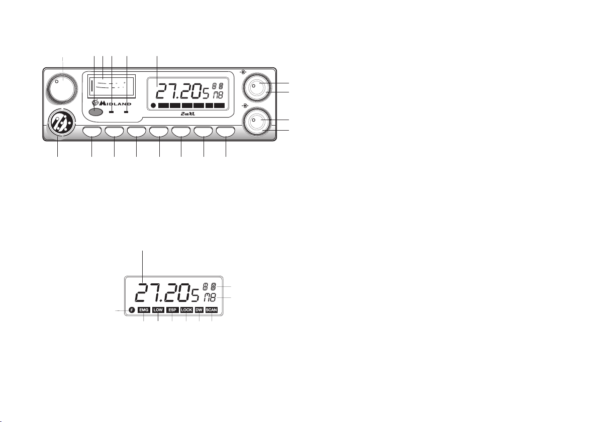
PANNELLO POSTERIORE
19 20 21 22
PA EXT
S-METER
ANTENNA
23
19. Connettore antenna: è previsto il connettore SO 239.
20. Presa S.METER: permette il collegamento di uno strumento esterno.
21. Presa PA: tramite il collegamento ad un altoparlante esterno, permette di
utilizzare l’apparato come amplificatore audio.
22. Presa EXT: presa altoparlante esterno (questo collegamento esclude l’uso
dell’alto parlante interno).
23. POWER 12.6 Vcc: presa di alimentazione.
INSTALLAZIONE
Ricercare e localizzare, sul mezzo mobile, la posizione per installare l’apparato, utilizzando la staffa di supporto in dotazione. Tale posizionamento
deve essere fatto in modo da non creare intralcio a chi guida, ma deve
anche essere facil mente accessibile. Praticare i fori (diametro di circa 3 mm.)
nella carrozzeria per il fissaggio con le viti. Posizionare l’apparato nella staffa di fissaggio. Controllare che le viti siano ben serrate, in considerazione
delle notevoli vibrazioni create dal mezzo mobile.
COLLEGAMENTO ELETTRICO
Prima di procedere in questa operazione, controllare che il ricetrasmettitore
sia spento (manopola del volume completamente girata a sinistra, dopo lo
scatto).
L’apparato é dotato di un cavetto di alimentazione bicolore con un portafusibile inserito sul cavo rosso (positivo). Nel collegamento, è molto importante rispettare la polarità anche se l’apparato é protetto contro l’inversione
accidentale. Di norma si identifica il polo positivo con il colore rosso o con il
segno ‘’+’’, e il polo negativo con il colore nero o con il segno “-”.
Gli stessi segni (o colori) identificativi li troveremo sulla batteria (accumulatore od altro) e nella scatola dei fusibili dell’automobile. Si raccomanda
di collegare in modo corretto e stabile i terminali del cavetto alla batteria.
ATTENZIONE
Per l’ottimizzazione delle prestazioni si consiglia l’installazione dell’apparecchiatura in luoghi che possano consentire un sufficiente riciclo d’aria.
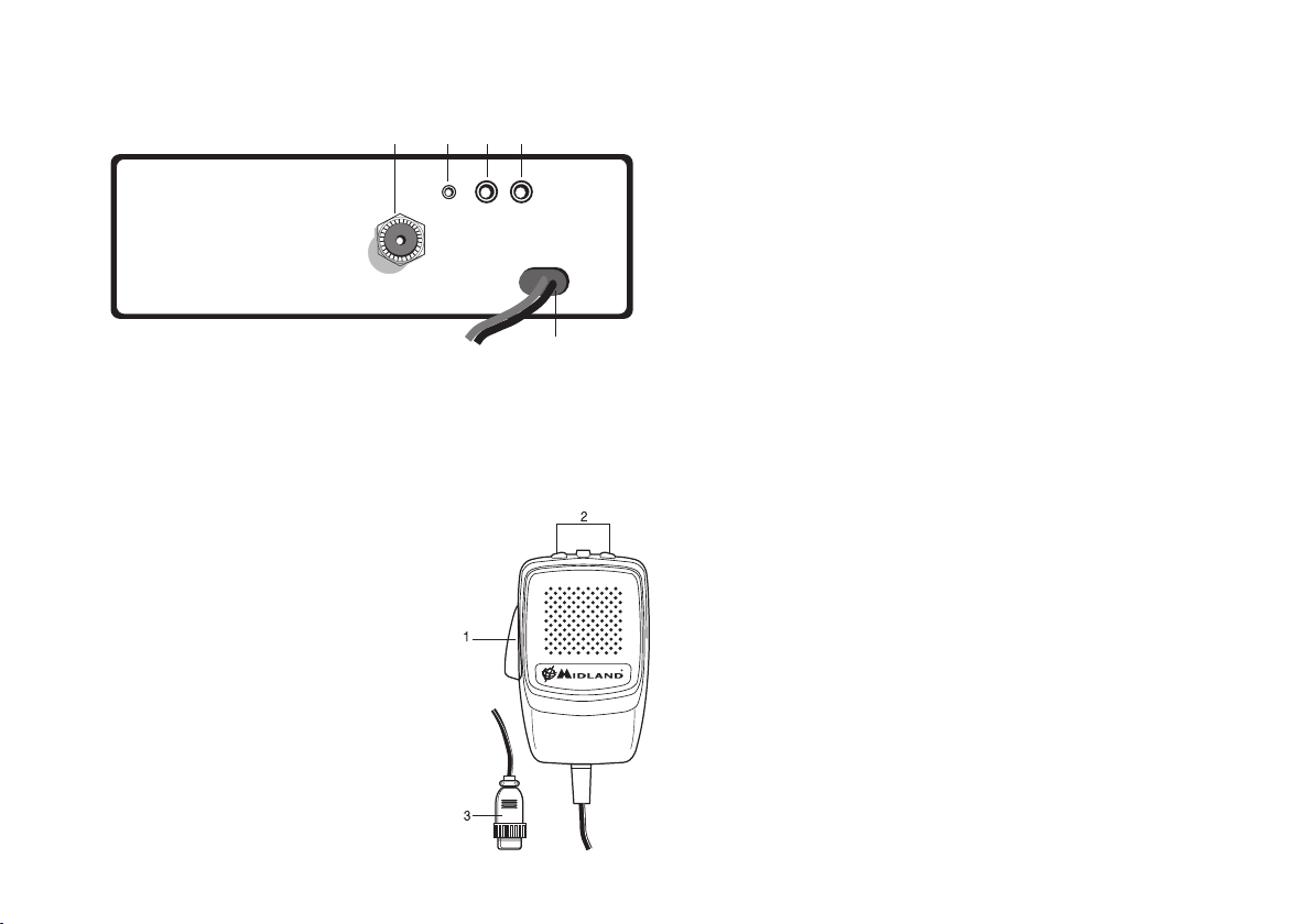
MICROFONO
1. PTT: Pulsante di trasmissione
2. Pulsanti UP/DOWN: selezione canali verso l’al-
to (UP) e verso il basso (DN)
3. Connettore microfonico 6 PIN
4
INSTALLAZIONE DELL’ ANTENNA
Informazioni utili :
1) Installare l’antenna nella parte più alta del veicolo.
2) Maggiore é la lunghezza dell’ antenna, migliore sarà il suo rendimento.
3) Se possibile, installare l’antenna al centro della superficie metallica scelta.
4) Tenere il cavo dell’ antenna lontano da fonti di disturbi elettrici.
5) Assicurarsi di avere una buona massa.
6) Evitare danni ai cavi.
Attenzione: non usare mai la radio CB senza aver installato un’ antenna
appropriata per non correre il rischio di danneggiare il trasmettitore; per
la stessa ragione con trollare periodicamente il ROS.
Page 7

SOSTITUZIONE DEL FUSIBILE
Sostituire il fusibile del cavo di alimentazione con un similare di tipo F 5A 250V. I
parametri ed il simbolo del fusibile sono indicati nella seguente etichetta:
F5A 250V +
USO DI MIDLAND 248XL
Dopo aver installato il vostro CB e la vostra antenna, seguire attentamente le
istruzioni qui sotto riportate per ottenere un funzionamento soddisfacente
del vostro apparato.
1) Avvitare la spina nella presa del microfono sul pannello.
2) Assicurarsi che l’antenna sia collegata al connettore dell’ antenna.
3) Assicurarsi che il comando di squelch sia completamente ruotato verso
sinistra.
4) Accendere l’apparato e regolare il comando del volume per un buon livello
sonoro.
5) Selezionare il canale desiderato, tramite il selettore canali o i tasti “UP /
DOWN” del microfono.
6) Per trasmettere, premere il pulsante di trasmissione PTT sul microfono.
7) Per ricevere, rilasciarlo.
SELEZIONE BANDE DI FREQUENZA
La scelta delle bande di frequenza deve essere eseguita a seconda del paese
nel quale si intende operare.
Procedimento:
1. Spegnere la radio.
2. Accendere l’apparecchio premendo il tasto “N.K.”.
3. Ruotare la manopola “CHANNEL” e selezionare la banda di frequenza desi-
derata (vedi tabella bande).
4. Premere il tasto “LOCK” per terminare la selezione.
NOTA: Se si seleziona una banda di frequenza che opera solamente la
modalità FM, il tasto “AM/FM” attiva la funzione LCR (richiamo ultimo
canale selezionato).
NOTA: Nella banda di frequenza UK, è possibile selezionare direttamente
la banda EC premendo il tasto “LCR-A/F” per 2 secondi circa.
TABELLA BANDE DI FREQUENZA
Sigla sul display Paese
I Italia 40 CH AM/FM 4Watt
I2 Italia 34 CH AM/FM 4Watt
D Germania 80 CH FM 4Watt / 12 CH AM 1 Watt
D2 Germania 40 CH FM 4Watt / 12 CH AM 1 Watt
D3 Germania 80 CH FM 4Watt / 40 CH AM 1 Watt
D4 Germania 80 CH FM 4Watt / 40 CH AM 4 Watt
EU Europa 40 CH FM 4Watt / 40 CH AM 1 Watt
EC 40 CH FM 4Watt
E Spagna 40 CH AM/FM 4Watt
F Francia 40 CH FM 4Watt / 40 CH AM 1 Watt
PL Polonia 40 CH AM/FM 4W
UK Inghilterra 40 CH FM 4Watt frequenze inglesi +
+ EC 40 CH FM 4Watt frequenze
ATTENZIONE:
Lo standard sicuramente riconosciuto in tutti i paesi europei è 40CH FM 4W
(EC)
– Vedi tabella “Restrizioni all’uso”
I
5
Page 8

CARATTERISTICHE TECNICHE
Generali
Canali ................................................................................................... (vedi tabella bande)
Gamma di frequenza* ..............................................................26.565 - 27.99125 MHz
Ciclo di utilizzo (% su 1 ora) ...................................... TX 5%; RX 5%; Stand-by 90%
Controllo di frequenza ...............................................................................................a PLL
Temperatura ...................................................................................................... -10° / +55°C
Tensione di alimentazione ..................................................................... 12.6 Vcc ±10%
Dimensione ...........................................................................150(L) x 45(A) x 175(P)mm
Peso .....................................................................................................................................1 Kg.
Ricevitore
Sistema ricevente .........................................Supereterodina a doppia conversione
Frequenza intermedia ........................................................................... I° IF:10.695 MHz
.............................................................................................................................. II° IF:455 KHz
Sensibilità .......................................................................... 0.5µV per 20dB SINAD in FM
...............................................................................................0.5µV per 20dB SINAD in AM
Potenza d‘ uscita audio @10% THD ....................................................2.0 W @ 8 Ohm
Distorsione audio ........................................................................Meno dell‘ 8% @ 1KHz
Reiezione alle immagini .............................................................................................65 dB
Selettività sul canale ...................................................................................................65 dB
Rapporto segnale disturbo .......................................................................................45 dB
Assorbimento all’ attesa ............................................................................12.6V: 450mA
Trasmettitore
Potenza d’uscita ......................................................................................................4W max
Modulazione ......................................................................................... AM:da 85% a 95%
..............................................................................................................FM:1,8 KHz ± 0,2 KHz
Frequenza di risposta..................................................................................300 Hz/3 KHz
Impedenza d’ uscita...................................................................RF 50 Ohm sbilanciato
Rapporto segnale disturbo ..............................................................................40 dB MIN
Corrente assorbita ......................................................................max a 12.6V: 2500mA
Un dispositivo di sezionamento adatto deve essere previsto nell’impianto elettrico.
Tale dispositivo deve disconnettere entrambi i poli simultaneamente.
CTE International dichiara che il prodotto è conforme ai requisiti essenziali e alle disposizioni della Direttiva del Consiglio 99/05/CE.
* (considerando tutte le bande di frequenza europee approvate)
Le specifiche sono soggette a modifiche senza preavviso.
6
Page 9

INDEX
Introduction ............................................................................................................................2
Function and location of the controls............................................................................3
Installation ...............................................................................................................................7
Power supply ..........................................................................................................................7
Installing an antenna ...........................................................................................................7
How to use your Midland 248XL ....................................................................................8
Frequency band selection ..................................................................................................8
Frequency band chart .........................................................................................................8
Specifications ..........................................................................................................................9
Midland 248XL is a mobile transceiver whose main feature is the possibility
to select any of the European CB bands with an easy and quick operation.
Midland 248XL is equipped with the “ESP2” and “NOISE BLANKER” (noise
reducer devices) that reduce considerably the audio noises up to 95%,
allowing a clear communication even when the signal is disturbed.
The wide multifunctional backlit display shows the number of the channel
in use or the correspondent frequency even in conditions of deep darkness.
Midland 248XL is also equipped with an analogical S-Meter, showing the
transmitted power and the signal received.
The unit is preset at the factory on the “EC“band, 40CH FM 4W.
UK
1
Page 10

FUNCTION AND LOCATION
2
8 9 10 11 12 13 14
OF THE CONTROLS
FRONT PANEL
1
CH
MIC
1. Channel selector: it permits the manual channel selection.
2. Microphone jack: insert the mic connector into this jack.
3. Indicator: this meter indicates the receiving signal strength and the
transmitter RF output power.
4. Multifunction backlighted display.
CB/PA
FUNC
01
0
3 4567
3
5
3
2
POWER
TX RX AM FM
M1
EMG
b
30
9
7
10
5
®
EMGDWESP LOCK SCANLOW
F
M3
M2
SCAN
DW
a
ecfdg
j
M4/LCR
AM/FM
LOCK
VOL
SQ
17
18
MIC
RF
16
N.K.M5
15
i
h
It shows:
a. channel selected number (from 1 up 40) or operative frequency
b. FUNC button activated
c. ESP: reducing noise device activated
d. DW: Dual Watch function activated
e. EMG: indicates channel being used or when the emergency channels
are activated
f. LOCK: keyboard lock function activated
g. SCAN function activated
h. M1-M2-M3-M4-M5: memory channel indicator
i. Indicates the frequency band selected.
j. It appears when the radio transmits in low power (this condition hap-
pens only in certain frequency bands – see the chart at the end of this
manual).
5. “AM/FM” Indicator
It indicates the operative mode. FM: red LED; AM: green LED.
6. “RX/TX” Indicator
LED indicating receiving or trasmitting mode. RX: green LED; TX: red LED.
7. “CB/PA” Selector
In the “CB” position, the unit operates as a transceiver. You can use the PA
(public address) function only if you connect a speaker to the PA jack (“PA”
visualized on the display). In this case the “MIC” knob controls the amplification level.
8. FUNC button
With the SCAN button, you can:
• visualize the operative frequency (if you keep pressing the button for 3
seconds approx.), or the channel in use;
• activate the second functions of the “M” (M1/M5) buttons.
M1 / M2 / M3 / M4 / M5:
Midland 248 XL has the possibility to store and to recall, when necessary, 5
channels previously memorized.
To memorize one channel, follow the procedure herebelow:
A) Select the channel with the appropriate selector or the “UP/DN” but-
tons on the microphone;
B) Push the “FUNC” button: the display will show “F”;
C) Keep pressing the “M1/EMG” button for 3 seconds: you will hear a “BIP”
and the display will show “M1”.
To memorize the other preset, repeat these steps and select another
2
Page 11

memory different from 1.
To recall a channel previously stored, push the “FUNC” switch and the
button of the desired memory.
These buttons have two functions; herebelow you will find their
descriptions:
9. “M1 - EMG” switch
This switch allows the storing of the first memory and the recalling of the
2 emergency channels. “M1 - EMG” selects sequentially channels 9 / 19
(emergency) and the one in use.
10. “M2 - DW” button
“M2 - DW” stores the chosen channel in the M2 memory and activates the
DUAL WATCH. This function allows the synthonization on two different
channels at the same time:
when a signal on the second channel is received, the conversation on
the first one is automatically interrupted and the receiver switches on the
second channel. The monitoring starts again 5 seconds after the signal end.
To activate this function, operate as follows:
- Select the desired channel through the channel selector or the “UP/
DOWN” buttons on the microphone;
- Keep the “DW” button pressed for about 3 seconds: you will hear a “BIP”
and “DW” will flash on the display.
- Select the second channel with the same procedure;
- Press the button “DW” again for roughly 3 seconds: you will hear another “BIP”; the display will permanently show “DW” and will alternatively visualize the two selected channels.
11. “M3 - SCAN” switch
The two functions of this button are: memorization of the third channel
in the M3 memory and “SCAN” function activation. In this case, you can
automatically seek for a busy channel:
• turn the squelch clockwise until the background noise is no longer
heard;
• press the “M3 - SCAN” button: “SCAN” will be shown on the display and
the transceiver will automatically scan all the channels until a carrier is
being received.
This function can be deactivated in three ways: pressing the PTT but-
ton, turning the channel selector or simply pushing any other button
on the unit.
12. “M4/LCR - AM/FM” button
Stores the memory number 4 and selects the operative mode (AM/FM).
AM: green LED; FM: red LED. If you select a frequency band operating in
FM modulation only, this button activates the LCR function (Last Channel
Recall).
13. “M5 - LOCK” switch
Pressing this button, you memorize the fifth (last) memory and activate the
“LOCK” function (it allows the locking of the keyboard, channel selector and
“UP/DN” buttons on the microphone, thus avoiding accidental use of the
keys).
14. N.K. button
Pressing this switch, you activate the reducing noise device (see introduc-
tion).
15. “MIC” knob
The amplification of the voice in TX must be adjusted with this knob. The
optimum level of the modulation must be found with the help of your
receiving partner.
16. “RF” knob
It controls the reception sensitivity.
To increase sensitivity, simply turn it clockwise. Sensitivity decreases turn-
ing it counterclockwise.
17. “VOL” knob
It allows the switching on of the unit and sets the volume to a comfortable
audio level.
18. “Squelch” knob
For the maximum receiver sensitivity, the control must be regulated exactly
where the receiver background noise disappears.
UK
3
Page 12

REAR PANEL
19 20 21 22
PA EXT
S-METER
ANTENNA
23
19. Antenna connector (SO239 connector type).
20. S.Meter jack: it allows an external “s meter” connection.
21. “PA” jack: by connecting with an external loudspeaker, you can use the unit
as an audio-amplifier.
22. ”EXT” jack: external loudspeaker jack (the internal loudspeaker is exclu-
ded).
23. Power 12.6 Vdc: power supply cable.
MICROPHONE
1. PTT: transmission button
2. UP/DOWN buttons: manual channel selector
3. 6 pin microphone connector
INSTALLATION
Safety and convenience are the primary consideration for mounting any
piece of mobile equipment. All controls must be readily available to the operator without interfering with the movements necessary for safe operation of
the vehicle. Set the proper position in the car to install the transceiver using
the supplied supporting bracket or eventually the slide bracket. Tighten the
retaining screws. The fixing bracket must be close to metallic parts.
POWER SUPPLY
Be sure the transceiver is off. In the direct-voltage power supply, to observe
the polarity is very important, even if the unit is protected against the accidental inversion:
Red = positive pole (+)
Black = negative pole (-)
The same colors are present on the battery and in the fuse box of the car.
Connect correctly the cable terminal to the battery.
ATTENTION
To obtain best performances we recommend to install the radio in a place
with enough air circulation.
INSTALLING AN ANTENNA
1. Place the antenna as high as possible.
2. The longer is the antenna, the better will be the performance.
3. If possible, mount the antenna in the center of whatever surface you choose.
4. Keep the antenna cable away from noise sources, such as the ignition
switch, gauges,etc.
5. Make sure you have a solid metal-to-metal ground connection.
6. Prevent cable damage during antenna installation.
WARNING. to avoid damage, never operate your CB radio without connecting a proper antenna. A periodical control of the SWR is recommended.
4
Page 13

REPLACING FUSE
If you replace the fuse for DC power Cord, use F 5A 250V type. The parameters and the symbol of the fuse are indicated in the following label.
F5A 250V +
HOW TO OPERATE WITH YOUR
MIDLAND 248XL
1. Screw the microphone plug into the microphone jack.
2. Make sure your antenna is securely connected to the antenna connector.
3. Make sure the SQUELCH control is turned fully counterclockwise.
4. Turn on the unit and adjust the volume control.
5. Select your desired channel through the “UP/DN” buttons on the microphone.
6. To transmit, press the PTT button and speak with a normal tone of voice.
7. To receive, release the PTT button.
FREQUENCY BAND SELECTION
The frequency bands must be chosen according to the country you are in.
Procedure:
1. Switch off the unit.
2. Turn it on while pushing the “N.K.” button.
3. Rotate the “CHANNEL” knob and select the desired frequency band (see
the chart here below).
4. To fix your selection, press the “LOCK” button.
NOTE: If you select a frequency band which operates in FM mode only, the
“AM/FM” control activates the LCR function (Last Channel Recall).
NOTE: In the UK frequency band, you can select directly the EC band by
pushing the “LCR-A/F” control for about 2 seconds.
FREQUENCY BAND CHART
Displayed digits Country
I Italy 40 CH AM/FM 4Watt
I2 Italy 34 CH AM/FM 4Watt
D Germany 80 CH FM 4Watt / 12 CH AM 1 Watt
D2 Germany 40 CH FM 4Watt / 12 CH AM 1 Watt
D3 Germany 80 CH FM 4Watt / 40 CH AM 1 Watt
D4 Germany 80 CH FM 4Watt / 40 CH AM 4 Watt
EU Europe 40 CH FM 4Watt / 40 CH AM 1 Watt
EC 40 CH FM 4Watt
E Spain 40 CH AM/FM 4Watt
F France 40 CH FM 4Watt / 40 CH AM 1 Watt
PL Poland 40 CH AM/FM 4Watt
UK England 40 CH FM 4Watt English frequencies +
+ EC 40 CH FM 4Watt frequencies
ATTENTION!
The frequency band allowed all over Europe is 40CH FM 4W (EC) – See the
“Restrictions on the use” table.
UK
5
Page 14

SPECIFICATIONS
GENERAL
Channels .................................................................... (see the Frequency band chart)
Frequency Range* ....................................................................26.565 - 27.99125 MHz
Duty cycle (% on 1 hour) ........................................ TX 5% - RX 5% - Stand-by 90%
Frequency Control .......................................................................................................... PLL
Operating Temperature Range ................................................................... -10°/+55° C
DC input voltage .......................................................................................12.6 Vdc ±10%
Size ...........................................................................................150(L) x 45(H) x 175(D)mm
Weight ..................................................................................................................................1Kg
RECEIVER
Receiving system .................................................Dual conversion superheterodyne
Intermediate frequency ..............................................I°IF:10.695 MHz II°IF:455 KHz
Sensitivity ................................................................... 0.5µV for 20dB SINAD in AM/FM
Audio output power @10% THD .........................................................2.0 W @ 8 Ohm
Audio distortion .............................................................................Less than 8% @ 1KHz
Image rejection .............................................................................................................. 65dB
Adjacent channel rejection .......................................................................................65dB
Signal/Noise ratio .......................................................................................................... 45dB
Current drain at stand/by ..........................................................................12.6V: 450mA
TRANSMITTER
Output power ..........................................................................................................4W max
Modulation ......................................................................................... FM:1.8KHz ± 0.2khz
....................................................................................................................... AM: 85% to 95%
Frequency response ................................................................................... 300 Hz/3 KHz
Output impedance ..................................................................RF 50 Ohm unbalanced
Signal/Noise Ratio ............................................................................................. 40 dB MIN
Current drain ................................................................................... max 12.6V: 2500 mA
A readily accessible disconnect device shall be incorporated in the installation wiring.
The disconnect device shall disconnect both poles simultaneously.
Hereby, CTE International declares that Midland 248 XL is in compliance with the essential requirements and other relevant provisions of Directive 99/05/EC.
* (covering all approved EU frequency bands)
Specifications are subject to change without notice.
6
Page 15

Inhaltsverzeichnis
Einleitung .................................................................................................................................2
Beschreibung der Bedienelemente ................................................................................3
Einbau im Kraftfahrzeug .....................................................................................................7
Anschluss an die Spannungsversorgung .....................................................................7
Montage der Antenne .........................................................................................................7
Bedienung des Midland 248XL .......................................................................................8
Auswahl der Frequenzbänder ..........................................................................................8
Frequenzbandtabelle...........................................................................................................9
Technische Daten ............................................................................................................... 10
Das Midland 248XL ist ein vielseitiges CB-Mobilfunkgerät, das sich
insbesondere durch die Frequenzbandwahl und das integrierte aktive
Rauschunterdrückungssystem ESP II hervorhebt.
Durch eine einfache Tastenkombination kann das Gerät bei einer
Auslandsreise auf die entsprechende Landesnorm umgeschaltet werden.
Die Funktionen der „ESP II“ und „NOISE BLANKER“ beruhen auf einen
optimierten Sprachfrequenzfilter, die sich automatisch in Abhängigkeit des
empfangenden Sprachsignals ein- bzw. ausschalten.
Im eingeschalteten Zustand werden die stark störenden Rauschanteile eliminiert und speziell die Sprachfrequenzen bevorzugt.
Im eingeschalteten Zustand werden die stark störenden Rauschanteile eliminiert und speziell die Sprachfrequenzen bevorzugt.
Das große Multifunktions-LC-Display mit Hintergrundbeleuchtung ist zu
jeder Tages- und Nachtzeit gut ablesbar und gibt Auskunft über alle
Betriebsparameter, wie z.B. Kanal- oder Frequenzanzeige.
Das integrierte analoge S-Meter zeigt die Intensität der eingehenden
Signale und die Sendeleistung an.
Ab Werk wird das Gerät auf dem Frequenzband „EC“ 40 Kanäle FM, 4 W eingestellt.
D
1
Page 16

Beschreibung der Bedienelemente
2
8 9 10 11 12 13 14
1
CH
MIC
1. Kanalwahlschalter: mit diesem Schalter lassen sich alle Kanäle einstellen.
2. Mikrofonbuchse: hier wird das Mikrofon angeschlossen.
3. S-Meter-Anzeige: zeigt die Intensität der eingehenden Signale sowie die
Sendeleistung an.
4. Multifunktions-Display mit Hintergrundbeleuchtung
a. Kanal- (von 1 bis 40) oder Frequenzanzeige.
b. F:Funktionstaste aktiviert.
c. ESP: Rauschunterdrückung aktiviert.
d. DW: Zweikanalüberwachung (DUAL WATCH) aktiviert
e. EMG: Direktschaltung auf Kanal 9 / 19 oder dem aktuell eingestellten
CB/PA
FUNC
01
0
3 4567
3
5
3
2
POWER
TX RX AM FM
M1
EMG
b
30
9
7
10
5
®
F
M3
M2
SCAN
DW
a
ecfdg
j
EMGDWESP LOCK SCANLOW
M4/LCR
AM/FM
LOCK
VOL
SQ
17
18
MIC
RF
16
N.K.M5
15
i
h
Kanal
f. LOCK: Mikrofon-Tastaturverriegelung (UP/DOWN) aktiviert.
g. SCAN: Kanalsuchlauf aktiviert
h. M1-M2-M3-M4-M5: Kanalspeicheranzeige .
i. Anzeige des gewählten Frequenzbandes.
l. erscheint, wenn das Funkgerät auf niedrige Sendeleistung schaltet (betrifft
nur bestimmte Frequenzbänder – siehe Frequenzbandtabelle im Anhang)
5. “AM/FM”-Anzeige
Zeigt die eingestellte Betriebsart an. FM: rote LED ; AM: grüne LED.
6. “RX/TX”-Anzeige
Sende- und Empfangsanzeige. Position RX: grüne LED; Position TX: rote LED.
7. Schalter für CB- und Durchsagebetrieb, CB/PA
Einstellung “CB” : In dieser Einstellung arbeitet das Gerät als CB-Funkgerät.
Einstellung “PA”: In dieser Einstellung arbeitet das Gerät im Durchsagebetireb
(Public Address), der nur aktiviert werden kann, wenn auf der Rückseite des
Funkgerätes ein Aussen-Lautsprecher angeschlossen wird (Schriftzug „PA“
erscheint im Display). In diesem Falle wird die Durchsage-Lautstärke über den
“MIC”-Drehregler eingestellt.
8. Funktionstaste FUNC
Über die Taste können folgende Funktionen aufgerufen werden:
• wird die “FUNC”-Taste ca. 3 Sekunden gedrückt gehalten, erscheint die
aktuelle Kanal- oder Frequenzeinstellung im Display
• ruft die Zweitfunktion der M-Tasten (M1/M5) auf.
M1 / M2 / M3 / M4 / M5
Mit den Speichertasten lassen sich fünf frei wählbare Kanäle programmieren
und auf Knopfdruck direkt einschalten. Zum Programmieren gehen Sie wie
folgt vor:
a) Wählen Sie über den Kanalwahlschalter oder die Up/Down-Tasten am
Mikrofon einen Kanal aus, den Sie im Kanalspeicher hinterlegen möchten.
b) Drücken Sie die Taste “FUNC”: Im Display erscheint ein “F”;
c) Halten Sie ca. 3 Sekunden die Taste “M1/EMG” gedrückt: Es ertönt ein
Signalton und im Display erscheint der Schriftzug “M1”.
Die Kanalspeicher M2 bis M5 können nun nach dem gleichen Verfahren mit
anderen Kanälen belegt werden.
Um einen gespeicherten Kanal aufzurufen, drücken Sie kurz die Taste „FUNC“
und die entsprechende Speicher-Taste (M1-M5) und das Gerät schaltet sofort
auf den gewünschten Kanal.
Bei den Kanalspeichertasten sind mit einer Doppelfunktion belegt, die im
nachfolgenden Text näher beschrieben wird.
2
Page 17

9. Taste “M1 - EMG”
Kanalspeicher Nummer 1 und Taste zum Aufrufen der Notrufkanäle.
Durch Drücken der Taste “M1/EMG” werden hintereinander die Kanäle 9, 19 und
der aktuell eingestellte Kanal aufgerufen.
10. Taste “M2 - DW”
K analspeicher Nummer 2 und Taste zum Aktivieren der Zweikanalüberwachung
(DUAL WATCH), die eine zeitgleiche Überwachung von zwei beliebigen Kanälen
Ihrer Wahl erlaubt.
Sobald auf einem dieser Kanäle ein Empfangssignal anliegt, das die eingestellte
Schwelle der Rauschsperre überschreitet, stoppt das Funkgerät auf diesem
Kanal und Sie hören das empfangende Signal. Fällt das Signal für längere Zeit
aus, schaltet das Funkgerät nach ca. 5 Sekunden wieder zwischen den beiden
eingestellten Kanälen hin und her. Einstellen der Zweikanalüberwachung:
1. Wählen Sie mit dem Kanalwahlschalter oder den UP-Down-Tasten am
Mikrofon, den ersten der zwei Kanäle aus, die Sie überwachen wollen.
2. Drücken Sie ca. 3 Sekunden lang die Taste „DW“: es ertönt ein Signalton
und im Display blinkt der Schriftzug „DW“.
3. Wählen Sie nun den zweiten Kanal aus.
4. Drücken Sie erneut ca. 3 Sekunden lang die Taste “DW”. Es ertönt ein
Signalton und der Schriftzug „DW“ wird konstant und die zu überwachenden Kanäle hintereinander im Display angezeigt.
11. Taste “M3 - SCAN”
Kanalspeicher Nummer 3 und Taste zum Aktivieren der Kanalsuchlauffunktion
“SCAN”
Durch Einschalten des Suchlaufbetriebs lassen sich belegte Kanä le automatisch
finden. Aktivieren des Suchlaufs:
1. Wählen Sie einen freien Kanal und stellen Sie die Rauschsperre so ein, daß
das Hintergrundrauschen gerade unterdrückt wird.
2. Drücken Sie die Taste “M3/SCAN”: Im Display erscheint der Schriftzug
„SCAN“ und das CB-Funkgerät startet den Suchlauf. Der Suchlauf stoppt,
sobald ein belegter Kanal gefunden ist.
Die Funktion “SCAN” kann auf 3 verschiedene Arten unterbrochen werden:
Durch Drücken der Sendetaste, durch Drehen des Kanalwahlschalters oder
durch Drücken einer beliebigen Taste.
12. Taste “M4/LCR - AM/FM”
Kanalspeicher Nummer 4 und Auswahl der Betriebsart. Bei Betriebsart FM
leuchtet die rote LED, bei Betriebsart AM die grüne LED.
Wird ein Frequenzband gewählt, das nur in der Betriebsart FM arbeitet, über-
nimmt die Taste “AM/FM” statt der Betriebsartwahl die LCR-Funktion (Last
Channel Recall – Aufruf des zuletzt genutzten Kanals).
13. Taste “M5 - LOCK”
Taste für Kanalspeicherbelegung Nummer 5 und Taste zum Aktivieren der
Sperrfunktion “LOCK” (Tastaturverriegelung, Kanalwahlschalter, Up/DownTaste am Mikrofon).
14. Taste “N.K.”
Aktivierte die Rauschunterdrückung (Siehe Einleitung).
15. Drehregler “MIC”, Mikrofon-Abschwächer
Im Sendebetrieb läßt sich mit diesem Regler die Lautstärke der
Modulation beeinflussen. Optimale Ergebnisse erreicht man, wenn man
den Regler in Abhängigkeit vom verwendeten Mikrofon und dem individuellen Sprechabstand einstellt und sich das beste Ergeb nis durch einen
Modulationsrapport einer Gegenstation bestätigen läßt.
Steht der PA-CB-Wahlschalter in der Stellung „PA“ wird mit dem „MIC“-
Drehregler die Durchsage-Lautstärke eingestellt.
16. Drehregler “RF”, HF-Abschwächer
Mit diesem Regler läßt sich die Eingangsempfindlichkeit herabsetzen.
Drehen im Uhrzeigersinn erhöht die Empfind lichkeit, Drehen gegen den
Uhrzeigersinn vermindert die Empfindlichkeit. Die Einstel lung einer verringerten Empfindlichkeit ist sinnvoll bei beson ders starken Stationen im Nahbereich.
17. Lautstärkeregler “VOL”
Über diesen Drehregler wird das Gerät ein- und ausgeschaltet und die Lautstärke
eingestellt. Drehen im Uhrzeigersinn erhöht die Wiedergabelautstärke.
18. Squelchregler “SQ”
Mit dem Squelchregler stellen Sie die Empfangs-Signalstärke ein, ab der Sie
Stationen (oder Rauschen) im Lautsprecher hören.
Um die höchstmögliche Empfangsempfindlichkeit zu nutzen, muß der Regler
so eingestellt werden, daß das Hintergrundrauschen gerade unterdrückt wird.
D
3
Page 18

Rückseite
19 20 21 22
PA EXT
S-METER
ANTENNA
23
19. Antennenbuchse (SO 239): Hier wird der Stecker des Antennenkabels mit dem
Funkgerät ver bunden.
20. S-Meter-Anschluß, S-Meter: An diese Buchse kann ein externes S-Meter ange-
schlossen werden.
21. PA-Buchse: wenn an dieser Buchse ein externer Durchsage-Lautsprecher ange-
schlossen ist, läßt sich das Gerät als Verstärker für Durchsagen einsetzen.
22. Anschluß für externen Lautsprecher, EXT: An diese Buchse kann ein externer
Wiedergabelautsprecher ange schlossen werden.
Der eingebaute Lautsprecher schaltet sich dann
automatisch stumm.
23. Buchse zum Anschluß der Spannungsversorgung,
Power 12.6 V: Über diese Buchse wird das 12 V
Anschlußkabel mit dem Gerät verbunden.
MIKROFON
1. PTT: Taste zur Sende-/Empfangsumschaltung
2. UP-/DOWN-Tasten: Kanalwahltasten
3. 6-poliger Mikrofonanschluß
Einbau im Kraftfahrzeug
Verkehrssicherheit und einfache Bedienbarkeit ohne Beeinträchti gung der
Verkehrssicherheit sollten beim Fahrzeugeinbau im Vor dergrund stehen. Suchen
Sie eine geeignete Einbauposition in Ihrem Fahrzeug und bauen Sie Ihr Midland
248XL mit Hilfe des Haltebügels allein oder unter Einsatz der Führungsschienen.
Der Haltebügel sollte möglichst Verbindung mit Metallteilen der Karos serie
haben.
Anschluß an die Spannungsversorgung
Stellen Sie zunächst sicher, daß Ihr Funkgerät ausgeschaltet ist. Es ist ganz wichtig,
daß Sie den Anschluß des Stromkabels polaritätsrichtig vornehmen. Dies gilt auch
dann, wenn Ihr Gerät gegen mögliche Verpolung geschützt ist:
Rote Kabelader = Pluspol (+)
Schwarze Kabelader = Minuspol (-)
Die gleichen Farben finden Sie an den Batteriepolen und manchmal auch im
Sicherungskasten Ihres Fahrzeugs. Schließen Sie die Kabelenden besonders
sorgfältig an die Stromversorgung des Fahr zeugs an.
ACHTUNG: es wird empfohlen, das Gerät an einem Ort mit sehr guter
Luftzirkulation anzubringen.
Montage der Antenne
1. Wählen Sie den Antennenstandort so hoch wie möglich.
2. Je größer die mechanische Länge der Antenne ist, desto bes ser wird die
Leistung sein.
3. Falls möglich, montieren Sie die Antenne in der Mitte der gewählten
Montagefläche.
4. Verlegen Sie das Antennenkabel möglichst weit entfernt von störenden
Aggregaten (Zündung, elektrischen Verbrauchern usw.).
5. Stellen Sie sicher, daß metallisch leitende Teile des An tennenfußes einen möglichst großflächigen Kontakt zum me tallisch blanken Karosserieblech haben.
6. Achten Sie darauf, daß das Antennenkabel bei der Montage nicht beschädigt
wird und sich durch Vibrationen im Fahrbetrieb nicht durchscheuern kann.
WARNUNG! Um Schäden zu vermeiden sollten Sie Ihr CB-Funkgerät niemals
ohne geeignete CB-Antenne betreiben. Darüber hinaus empfehlen wir Ihnen,
das Antennenkabel sowie das Stehwellenverhältnis (SWR) in regelmäßigen
Abständen zu überprüfen.
Erkundigen Sie sich, ob der Fahrzeughersteller Vorschriften für den
Antenneneinbau herausgegeben hat. Nach den gesetzlichen Bestimmungen
4
Page 19

hat der Hersteller das Recht, falls notwendig, Einbauvorschriften für Antennen
und Funkgeräte zu erlassen, an die Sie sich halten müssen. Nichtbeachtung der
Einbauvorschriften kann zu Problemen durch Einstrahlung von HF Energie in die
Fahrzeugelektronik führen, u.U. erlischt sogar die Betriebserlaubnis des Fahrzeugs.
SICHERUNG ERSETZEN
Zum Ersetzen der Sicherung im DC-Kabel verwenden Sie bitte eine 5 A Sicherung
(Typ “F” für 250 V).
F5A 250V +
Bedienung des Midland 248XL
Nachdem Sie Ihr CB-Funkgerät an die Spannungsversorgung angeschlossen und
die Antenne korrekt montiert haben, befolgen Sie nachfolgende Anweisungen:
1. Stecken Sie den Mikrofonstecker in die Mikrofonbuchse.
2. Stellen Sie sicher, daß Ihre Funkantenne über das Antennen kabel fest und sicher
mit der Antennenanschlußbuchse verbunden ist.
3. Vergewissern Sie sich, daß die Rauschsperre (Squelch) ge öffnet ist, d. h. der
Regler bis zum Anschlag gegen den Uhrzeigersinn gedreht ist.
4. Schalten Sie Ihr CB-Funkgerät ein und stellen Sie die Wie dergabelautstärke nach
Ihren persönlichen Wünschen ein.
5. Stellen Sie über den Kanalwahlregler oder die Up/Down-Tasten am Mikrofon
den gewünschten Funkkanal ein.
6. Zum Senden drücken Sie die PTT-Taste und besprechen das Mikrofon mit normaler Lautstärke und Tonlage.
7. Zum Empfangen lassen Sie einfach die PTT-Taste wieder los.
Auswahl der Frequenzbänder
Bei der Auswahl der Frequenzbänder sind die Vorschriften der Länder zu beachten,
in denen das Funkgerät betrieben wird.
Umschalten der Ländereinstellung:
1. Schalten Sie das Funkgerät aus.
2. Schalten Sie das Funkgerät wieder ein und halten Sie dabei gleichzeitig die Taste
„N.K.“ gedrückt.
3. Drehen Sie den Kanalwahlschalter “CHANNEL” und wählen Sie das gewünschte
Frequenzband aus (siehe Frequenzbandtabelle).
4. Drücken Sie die Taste “LOCK”, um die Auswahl zu bestätigen.
Anmerkung: Wird ein Frequenzband gewählt, das nur in der Betriebsart FM arbeitet, übernimmt die Taste “AM/FM” statt der Betriebsartwahl die LCR-Funktion (Last
Channel Recall – Aufruf des zuletzt genutzten Kanals).
NOTIZ: Auf dem Frequenzband UK besteht die Möglichkeit das Frequenzband
EC direkt auszuwählen. Halten Sie dazu die Taste “LCR-A/F” ca. zwei Sekunden
gedrückt.
Frequenzbandtabelle
Anzeige im Display Land
I Italien 40 Kanäle, AM/FM, 4 Watt
I2 Italien 34 Kanäle, AM/FM, 4 Watt
D Deutschland 80 Kanäle FM, 4 Watt / 12 Kanäle AM, 1 Watt
D2 Deutschland, 40 Kanäle FM, 4 Watt / 12 Kanäle AM, 1 Watt
D3 Deutschland 80 Kanäle FM, 4 Watt / 40 Kanäle AM, 1 Watt
D4 Deutschland 80 Kanäle FM, 4 Watt / 40 Kanäle AM, 4 Watt
EU Europa 40 Kanäle FM, 4 Watt / 40 Kanäle AM, 1 Watt
EC 40 Kanäle FM, 4 Watt
E Spanien, 40 Kanäle AM/FM, 4 Watt
F Frankreich 40 Kanäle FM, 4 Watt / 40 Kanäle AM, 1 Watt
PL Polen 40 CH AM/FM 4Watt
UK England 40 Kanäle FM 4 Watt Englische Frequenzen +
EC 40 Kanäle FM 4 Watt Frequenzen
ACHTUNG:
In den meisten europäischen Ländern wird die Standardeinstellung 40 Kanäle
FM, 4 W (EC) – akzeptiert. In Deutschland ist für den Betrieb in den deutschen
Programmiereinstellungen d1....d4 (ab Freigabe) als Mobilfunkgerät keine
Anmeldung mehr erforderlich. Einschränkungen gelten für die Kanäle 41 -80
bei Feststationen in Grenznähe.
D
5
Page 20

Technische Daten
Allgemein
Kanäle ........................................................................ bzw. entspr. der Frequenzbandtabelle
technisch möglicher
Frequenzbereich* .................................................................................26.565 - 27.99125 MHz
Frequenzbelegungsdauer (% pro 1 Stunde) .............. TX 5% - RX 5% - Stand-by 90%
Frequenzaufbereitung ....................................................................PLL, prozessorgesteuert
Betriebstemperaturbereich .............................................................................-10°C bis +55°C
Spannungsversorgung ......................................................................................12.6 VDC ±10%
Abmessungen ................................................................................150(L) x 45(A) x 175(P)mm
Gewicht ........................................................................................................................................1 Kg.
Empfänger
Empfangsprinzip ..................................................................................................... Doppelsuper
Zwischenfrequenzen ..................................................................................... 1. ZF:10.695 MHz
...................................................................................................................................... 2. ZF: 455 KHz
Empfindlichkeit ..................................................... besser als 0.5µV bei 20dB SINAD in FM
NF-Wiedergabeleistung an 8 Ohm ...........................................2.0 W bei 10 % Klirrfaktor
Spiegelfrequenzunterdrückung .......................................................................................65 dB
Nachbarkanaldämpfung ..................................................................................................... 65 dB
Geräuschspannungsabstand ........................................................................ besser als 45 dB
Ruhestromaufnahme ........................................................................................... 12.6V: 450mA
Sender
Sendeleistung ................................................................................................................... 4 W max
Modulation .................................................................................. Mod-Grad AM: 85% bis 95%
...............................................................................................................Hub FM:1,8 KHz ± 0,2 KHz
Sendefrequenzgang ...............................................................................................300 Hz/3 KHz
Ausgangsimpedanz .......................................................................................................... 50 Ohm
Geräuschspannungsabstand ........................................................................ besser als 40 dB
Stromaufnahme ...................................................................................................12.6V: 2500mA
Abweichungen von den Technischen Daten im Zuge der Weiterentwicklung bleiben
vorbehalten.
Direkter Anschluss des Gerätes an DC Netze ist nur über eine entsprechende Sicherung
zulässig.
Hiermit erklärt CTE International, dass dieses Gerät den grundlegenden Anforderungen
sowie weiteren relevanten Bestimmungen der EU-Richtlinie 99/05/EC entspricht.
* (Abdeckung aller in der EU erlaubten Frequenzbänder)
6
Page 21

INDICE
Introducción ............................................................................................................................2
Funciones y posición de los controles ...........................................................................3
Instalación ................................................................................................................................7
Conexión eléctrica ................................................................................................................7
Instalación de la antena ......................................................................................................7
Funcionamento del transceptor ......................................................................................8
Selección bandas de frecuencia.......................................................................................8
Tabla bandas de frecuencia ...............................................................................................8
Especificaciones técnicas ...................................................................................................9
La utilización de transceptores CB27, está supeditada a la obtención de la correspondiente licencia admi nistrativa.
Para obtener toda la información necesaria al respecto, diríjase a la Jefatura Provincial
de Telecomunicaciones de su provincia.
También podrá obtener toda la información que necesite llamando al 913 461 500 o
bien, en la página web del Ministerio de Ciencia y tecnología www.sgc.mfom.es/
directorio/directorio.htm, donde encontrará un práctico acceso a los datos de todas
las Jefaturas Provinciales.
Asimismo, tanto nuestra página web www.alan.es como el teléfono de atención al cliente 902 384878, le mantendrán puntualmente informado de las novedades legales y los
requisitos necesarios para éste y otros trámites relacionados con la CB.
INTRODUCCIÓN
El Midland 248XL representa el máximo exponente en la nueva generación
de equipos CB al haberse utilizado en su diseño y producción la más avanzada tecnología en ingeniería electrónica.
Presenta además dos novedades exclusivas. En primer lugar, dispone de
todas las especificaciones europeas por lo que podrá usarlo en todos los
países que se indican en la “Tabla de Restricciones al Uso” que acompaña al
presente manual. Bastará con seleccionar las siglas correspondientes al país
en cuestión.
Dotado de todos los controles y funciones necesarios para satisfacer al más
exigente de los radioaficionados, la calidad de los materiales empleados en
su fabricación, su versatilidad y funcionalidad le harán disfrutar de excelentes
momentos de radio a la vez que generará una sana envidia en sus compañeros de radio.
Es un equipo electrónico de alta calidad, hábilmente construido con los
mejores componentes. La circuitería es de estado sólido montada sobre
robustas placas de circuito impreso. Su diseño le permitirá trabajar con esta
unidad durante muchos años, sin ninguna merma en sus prestaciones.El
circuito PLL utiliza los últimos avances tecnológicos para generar todas las
frecuencias requeridas con un mínimo de cristales de cuarzo. El resultado es
un control más eficiente de las frecuencias y una superior fiabilidad. Otras
características que diferencian a el Midland 248XL del resto de equipos del
mercado son el dispositivo ESP 2 (supresor dinámico de ruido) y el disponer
de un S-METER analógico en un equipo digital.
Las innovadoras funciones del dispositivo “ESP 2” y “NOISE BLANKER” son
las de reducir notablemente los ruidos del audio, facilitando la recepción de
señales limpias y atenuando las señales distorsionadas. De esta manera, la
escucha es más comprensible y agradable.
La inclusión de un S-METER analógico en un equipo totalmente digital,
responde a las preferencias mostradas por los radioaficionados que, aunque
valoran muy positivamente los digitales, prefieren la inmediatez y facilidad
de lectura de uno analógico.
Estamos convencidos de que Vd. Acaba de adquirir uno de los mejores equipos CB que existen en el mercado. Disfrútelo.
El equipo viene de origen sintonizado en la banda “EC” 40CH FM 4W.
E
1
Page 22

FUNCIONES Y POSICIÓN
2
8 9 10 11 12 13 14
DE LOS CONTROLES
1
CH
MIC
1. Selector de canales: permite la selección manual del canal deseado.
2. Toma para el micrófono: Inserte el conector del micrófono en este jack.
3. S-METER: este instrumento indica la intensidad de las señales recibidas y la
potencia de salida RF en transmisión.
4. Display multifunción retro-iluminado: la información que muestra es la
siguiente:
CB/PA
FUNC
01
0
3 4567
3
5
3
2
POWER
TX RX AM FM
M1
EMG
b
30
9
7
10
5
®
F
M3
M2
SCAN
DW
a
ecfdg
j
EMGDWESP LOCK SCANLOW
M4/LCR
AM/FM
LOCK
VOL
SQ
17
18
MIC
RF
16
N.K.M5
15
i
h
a. El número del canal seleccionado (de 1 a 40) o la frecuencia correspon-
diente.
b. Activación tecla FUNC.
c. ESP : activación supresor dinámico de ruidos.
d. DW: función DUAL WATCH (Doble Escucha) activada.
e. EMG: indicador activación canal 9/19 o canal en uso.
f. LOCK: indicador de activación de la función de bloqueo de teclado y
selectores.
g. SCAN: indicador de función SCAN (Barrido) activada.
h. M1-M2-M3-M4-M5: indicador de canales de memoria.
i. Indica la banda de frecuencia seleccionada
j. Se visualiza cuando el equipo transmite en baja potencia (sólo en
determinadas bandas de frecuencia – vea la tabla de bandas)
5. Indicador AM/FM: indica el modo operativo. FM: LED rojo; AM: LED verde.
6. Indicador RX/TX: indicador de recepción/transmisión. RX: LED verde; TX:
LED rojo.
7. Selector CB-PA: situado en CB, el equipo actúa como transceptor. En posi-
ción PA, si se conecta un altavoz a la toma posterior PA, el equipo se convierte en un amplificador de BF, actuando el mando MIC como regulador
de la amplificación.
8. Tecla FUNC: permite visualizar, a elección del usuario:
• El canal o la frecuencia operativa pulsando FUNC durante 3 segundos.
• Activar la segunda función de las teclas M (M1-M5).
M1 / M2 / M3 / M4 / M5: el equipo tiene la posibilidad de memorizar 5
canales cualesquiera. Para memorizar uno, proceda como sigue:
• Seleccione el canal que desea memorizar mediante el selector de canales
o mediante los pulsadores UP/DOWN del micrófono.
• Pulse la tecla FUNC: en el display aparecerá “F”.
• Mantenga pulsada durante 3 segundos la tecla M1/EMG (si desea grabar
en la memoria M1): El equipo emitirá un bip y en el display aparecerá “M1”.
Para memorizar otros canales en las restantes memorias, repita los puntos
a, b y c, cambiando en este último la memoria (M2-M5).
Para llamar un canal memorizado, pulse FUNC + la tecla correspondiente
a la memoria deseada (M1-M5).
Las teclas de memoria tienen una doble función, la segunda de las
cuales, pasamos a describir a continuación:
9. M1 - EMG: selecciona cíclicamente, además de grabar o llamar la memoria
1, el canal 9, 19 y el canal en uso.
2
Page 23

10. M2 - DW: permite la grabación o llamada de la memoria 2 y la activación de
la función DUAL WATCH –Doble Escucha- que faculta al equipo a sintonizar
simultáneamente dos canales cualesquiera escogidos por el usuario.
Con esta función se monitorizará cíclicamente un segundo canal además
del que esté en uso. Ante la presencia de señal en el segundo canal, la
comunicación en el canal en uso se interrumpirá y el receptor conmutará
automáticamente al segundo canal. La monitorización se reiniciará transcurridos 5 segundos del cese de la señal en el segundo canal.
Para activar esta función, siga las siguientes instrucciones:
– Seleccione el canal principal o canal de uso mediante los selectores de
cambio de canal.
– Pulse la tecla DW durante 3 segundos: el equipo emitirá un bip y en el
display parpadeará “DW ”.
– Seleccione el segundo canal. Normalmente se escoge un canal en el
que puedan aparecer informaciones importantes, pero que no tenga
un tráfico excesivo, ya que esto haría que el equipo estuviese conmutando continuamente a este canal, con la incomodidad que esto acarrearía. Podríamos considerar el canal de emergencia 9 u otro canal con
las citadas características.
– Pulse nuevamente la tecla DW durante 3 segundos: el equipo emitirá
un bip y el display mostrará “DW” permanentemente, visualizando
alternativamente los dos canales seleccionados.
11. M3 - SCAN: mediante esta tecla, además de grabar o llamar la memoria
3, se activa la función SCAN –Barrido- que hace que el equipo inicie una
búsqueda automática de canal ocupado. Para activar esta función:
– Seleccione un canal libre y gire el control de squelch en sentido horario
hasta que el ruido de fondo desaparezca.
– Pulse SCAN: el display mostrará la palabra “SCAN” y el equipo iniciará la
búsqueda automática que durará hasta que encuentre una señal o se
desactive manualmente. Esta desactivación manual se puede efectuar
de tres formas diferentes: pulsando el PTT, girando el selector de canales o pulsando cualquier tecla.
12. M4/LCR - AM/FM: además de permitir llamar o grabar la memoria 4, per-
mite seleccionar el modo operativo: AM (led 5 verde) o FM (led 5 rojo). Si
además selecciona una banda de frecuencia que opera en modo FM, la
tecla “AM/FM” activa la función LCR (rellamada último canal utilizado)
13. M5 - LOCK: permite llamar o grabar la memoria 5. Además, sirve para blo-
quear el teclado y el conmutador de canales, evitando así el cambio acci-
dental de los parámetros de uso del equipo. Permite no obstante, regular
el volumen, squelch, ganancia de micro y ganancia de RF.
14. N.K.: activa el supresor dinámico de ruidos ESP 2.
15. Mando MIC: controla la amplificación microfónica en transmisión. La posi-
ción óptima de este control, se consigue experimentalmente hasta que
se obtiene la mejor modulación posible. Varíe el mando y solicite a otros
usuarios que valoren su modulación, actuando en consecuencia.
16. Mando RF: controla la sensibilidad en recepción, girando el mando en
sentido horario se aumenta la sensibilidad y viceversa. Tenga la precaución
de disminuir la sensibilidad cuando las señales recibidas sean muy fuertes
ya que así mejorará sensiblemente la calidad en recepción.
17. Mando VOL: enciende/apaga el equipo y regula el nivel de audio del alta-
voz
18. Mando SQ: permite regular el umbral de recepción. Para una máxima sen-
sibilidad del receptor, es preferible que se regule el mando al nivel en que
el ruido de fondo desaparece.
E
3
Page 24

PANEL POSTERIOR
19 20 21 22
PA EXT
S-METER
ANTENNA
23
19. CONECTOR ANTENA: conector del tipo SO239.
20. TOMA S-METER: permite la conexión de un medidor de señal externo.
21. TOMA PA: conectando un altavoz de exteriores a este jack, puede usar la
unidad como amplificador de audio.
22. TOMA EXT: jack para la conexión de un altavoz externo (al conectarlo, el
interno queda desactivado).
23. POWER 12.6 VCC: toma de alimentación.
MICRÓFONO
1. PTT: botón de transmisión
2. Pulsadores UP/DOWN: Selector manual de
canales.
3. Conector del micrófono de 6 pines
INSTALACIÓN
La seguridad y la facilidad son las consideraciones primordiales para efectuar
el montaje de cualquier equipo móvil. Todos los controles deben ser fáciles
de alcanzar por parte del operador, sin que ello interfiera en la correcta conducción del vehículo. Seleccione la posición adecuada del vehículo donde
instalar el transceptor y use el soporte suministrado o eventualmente el
soporte deslizante. Coloque los tornillos de retención. El soporte de fijación
debe estar en contacto con las partes metálicas.
CONEXIÓN ELÉCTRICA
Asegúrese de que el transceptor está apagado. El equipo incluye un cable de
alimentación bicolor con un portafusibles insertado en el cable rojo (positivo). En la alimentación de corriente continua es muy importante observar la
polaridad, incluso si la unidad está protegida contra la inversión accidental.
Como norma, se identifica el polo positivo con el color rojo o con el signo “+”,
y el polo negativo con el color negro o con el signo “-“
Los mismos colores se encuentran presentes en la batería y en la caja de fusibles del vehículo. Conecte correctamente el terminal del cable a la batería.
INSTALACIÓN DE LA ANTENA
1. Instale la antena lo más alta posible.
2. Cuanto más larga sea la antena, mejores prestaciones obtendrá.
3. Si es posible, monte la antena en el centro de la superficie escogida.
4. Mantenga el cable de antena a resguardo de fuentes de ruido eléctrico,
tales como del encendido del coche, etc.
5. Asegúrese de que dispone de una sólida conexión a masa metal a metal.
6. Impida que pueda dañarse el cable durante la instalación de la antena.
Advertencia: Para evitar provocar daños, nunca utilice su equipo sin asegurarse de que está correctamente conectado a una antena adecuada. Se
recomienda un control periódico del cable y de la ROE.
CAMBIO DEL FUSIBLE
Si debe cambiar el fusible del cable de alimentación, utilice uno del tipo F
5A 250V. Los parámetros y el símbolo del fusible se indican en la siguiente
etiqueta:
4
Page 25

F5A 250V +
FUNCIONAMIENTO DEL TRANSCEPTOR
1. Enchufe el micrófono en el jack correspondiente.
2. Asegúrese de que la antena está conectada al conector correspondiente.
3. Asegúrese de que el control del silenciador está girado completamente
hacia la izquierda.
4. Encienda la unidad y ajuste el control de volumen y squelch.
5. Seleccione el canal deseado.
6. Para transmitir, pulse el botón PTT y hable en un tono de voz normal.
7. Para recibir, libere el botón PTT.
SELECCIÓN BANDAS DE FRECUENCIA
La selección de las bandas de frecuencia debe efectuarse en función del país
en el que se va a utilizar el equipo.
Procedimiento:
1. Apague el equipo
2. Enciéndalo pulsando la tecla “N.K.”
3. Gire el mando “CHANNEL” y seleccione la banda de frecuencia deseada (“E”
para España – vea la tabla de bandas más abajo)
4. Pulse la tecla “LOCK” para finalizar la selección
NOTA: Si se selecciona una banda de frecuencia que sólo funciona en
modo FM, la tecla “AM/FM” activa la función LCR (rellamada último canal
utilizado)
NOTA: en la banda de frecuencia UK se puede seleccionar directamente
la banda EC pulsando la tecla “LCR-A/F” durante aproximadamente 2
segundos
TABLA BANDAS DE FRECUENCIA
Siglas en el display País
I Italia 40 CH AM/FM 4W
I2 Italia 34 CH AM/FM 4W
D Alemania 80 CH FM 4W / 12 CH AM 1 W
D2 Alemania 40 CH FM 4W / 12 CH AM 1 W
D3 Alemania 80 CH FM 4W / 80 CH AM 1 W
D4 Alemania 80 CH FM 4W / 40 CH AM 4 W
EU Europa 40 CH FM 4W / 40 CH AM 1 W
EC 40 CH FM 4W
E España 40 CH AM/FM 4W
F Francia 40 CH FM 4W / 40 CH AM 1 W
PL Polonia 40 CH AM/FM 4W
UK
ATENCIÓN: El estándar reconocido en todos los países europeos es 40CH
FM 4W (EC) – Vea tabla de “Restricciones al uso”
Inglaterra 40 CH FM 4W frecuencias inglesas +
EC 40 CH FM 4W frecuencias
E
5
Page 26

ESPECIFICACIONES TÉCNICAS
Generales
Canales ................................................................................................... (vea tabla bandas)
Rango de frecuencias ....................................................................26.965 - 27.405 MHz
Ciclo de trabajo (% en 1 hora) ............................... TX 5% - RX 5% - Stand-by 90%
Control de frecuencia ..................................................................................................... PLL
Gama de temperaturas de operación ............................................... -10 ºC a +55 ºC
Tensión de alimentación ........................................................................12.6 Vcc ± 10%
Dimensiones .................................... 150 (ancho) x 45 (alto) x 175 mm (profundo)
Peso ..................................................................................................................................... 1 Kg
Receptor
Sistema de recepción.................................Superheterodino de doble conversión
Frecuencia intermedia .........................................................................1ª FI: 10.695 MHz
.............................................................................................................................2ª FI: 455 KHz
Sensibilidad ....................................................0.5 µV para 20 dB SINAD en modo FM
............................................................................0.5 µV para 20 dB SINAD en modo AM
Potencia de salida de audio a 10% THD .....................................2,0 W @ 8 Ohmios
Distorsión de audio ....................................................................Menos de 8% @ 1 KHz
Rechazo de imagen .....................................................................................................65 dB
Rechazo del canal adyacente...................................................................................65 dB
Relación señal/ruido ...................................................................................................45 dB
Consumo de corriente en espera .................................................... 12.6 Vcc: 450 mA
Transmisor
Potencia de salida ..................................................................................................4 W max
Modulación....................................................................................AM: desde 85% a 95%
.............................................................................................................FM: 1.8 KHz ± 0.2 KHz
Respuesta de frecuencia ............................................................................ 300 Hz/3 KHz
Impedancia de salida ................................................ RF 50 Ohmios no balanceados
Relación señal/ruido .................................................................................. 40 dB mínimo
Consumo ................................................................................................12.6 Vcc: 2500 mA
“CTE International SRL, declara, bajo su responsabilidad, que este aparato cumple con lo
dispuesto en la Directiva 99/05/CE, del Parlamento Europeo y del Consejo de 9 de marzo de
1999, transpuesta a la legislación española mediante el Real Decreto 1890/2000, de 20 de
noviembre”.
Todas las especificaciones están sujetas a cambio sin previo aviso.
El cable de alimentación incorpora un dispositivo de fácil desconexión.
Dicho dispositivo desconecta los dos polos simultáneamente.
6
Page 27

SOMMAIRE
Introduction ............................................................................................................................2
Description des commandes ............................................................................................3
Installation ...............................................................................................................................7
Branchement électrique .....................................................................................................7
Installation de l’antenne .....................................................................................................7
Comment utiliser de Midland 248XL ............................................................................8
Sélection des bandes de fréquence ...............................................................................8
Tableau des bandes de fréquence ..................................................................................8
Caractéristiques techniques ..............................................................................................9
Midland 248XL est un émetteur-récepteur dont la caractéristique principale
est la possibilité de sélectionner n’importe quelle bande CB européenne avec
une procédure simple et immédiate.
Midland 248XL est doué des dispositifs “ESP2” et “NOISE BLANKER” (suppresseur dynamique des parasites) qui réduit les bruits indésirables sur
l’audio jusqu’à 95% en facilitant l’écoute des signaux purs et en atténuant
les signaux gênants.
De cette façon, l’écoute sera plus compréhensible et agréable.
Le large afficheur multi-fonction permet la visualisation du nombre du canal
en usage ou de la fréquence correspondante. Il est aussi retro-éclairé en
facilitant l’usage nocturne.
Midland 248XL est doué d’un S-Metre analogique indiquant la puissance
d’émission, le signal reçu.
L’unité est pre-réglée en usine sur la bande “EC“ 40CH FM 4W.
F
1
Page 28

DESCRIPTION DES COMMANDES
2
8 9 10 11 12 13 14
PANNEAU FRONTAL
1
CH
MIC
1. Sélecteur canaux: il permet la sélection manuelle des canaux.
2. Prise microphone: insérer la fiche microphone dans cette prise.
3. Indicateur: cet instrument indique l’intensité des signaux en réception et la
puissance de sortie RF de l’émetteur.
4. L’afficheur illuminé multi fonctions
CB/PA
FUNC
01
0
3 4567
3
5
3
2
POWER
TX RX AM FM
M1
EMG
b
30
9
7
10
5
®
F
M3
M2
SCAN
DW
a
ecfdg
j
EMGDWESP LOCK SCANLOW
M4/LCR
AM/FM
LOCK
VOL
SQ
MIC
RF
N.K.M5
i
h
a) Nombre canaux sélectionnés (de 1 à 40) ou fréquence correspondante
b) Activation bouton FUNC
c) ESP : activation suppression dynamique des bruits de fond
d) DW : fonction DUAL WATCH activée
e) EMG : indicateur fonction bloc boîtier et sélecteur activé
f) LOCK : indicateur fonction LOCK activé
g) SCAN : indicateur fonction SCAN activé
h) M1-M2-M3-M4-M5: indicateurs mémoire canaux.
i) Indique la bande de fréquence sélectionnée.
17
18
j) Il est visualisé quand la radio transmet en basse puissance (condition
qui se vérifie seulement pour certaines bandes de fréquence – voir le
tableau des bandes)
5. Indicateur « AM/FM» : indique le mode opératif. FM LED: rouge –
AM : LED verte.
16
6. Indicateur « RX/TX »: indicateur de réception/transmission.
15
Position RX : LED verte – position TX : LED rouge.
7. Sélecteur « CB-PA»
Position CB: dans cette position, l’appareil est activé comme émetteur-
récepteur.
Position PA : ce mode de fonctionnement est possible seulement si on
branche un haut-parleur à la prise PA à l’arrière (écrit « PA » visualisée sur le
l’afficheur). Dans ce cas, la commande « MIC » est utilisée comme contrôle
de l’amplificateur.
8. Bouton FUNC: ce bouton permet, au choix, de :
• Visualiser le canal ou la fréquence opérative en appuyant sur « FUNC »
pendant 3 secondes environ;
• Activer la seconde fonction des boutons «M » (M1/M5).
M1/M2/M3/M4/M5
La radio a la possibilité de mémoriser et de rappeler 5 canaux au choix
précédemment mémorisés. Pour mémoriser, procéder comme suit :
A. Sélectionner le canal que l’on désire mémoriser avec le sélecteur canal
ou le bouton « UP/DOWN » sur le microphone ;
B. Appuyer sur le bouton « FUNC » : l’afficheur montrera un « F »;
C. Tenir appuyer pendant 3 secondes environ le bouton «M1/EMG » : la
radio émettra un «bip » et l’afficheur montrera l’écriture «M1 ».
9. Bouton « M1 – EMG»
Il permet de mémoriser la mémoire n° 1 et de rappeler le canal d’urgence
La pression du bouton « M1/EMG » sélection les canaux 9, 19 et le canal en
2
Page 29

usage.
10. Bouton « M2 – DW»
Permet la mémorisation de la mémoire numéro 2 et l’activation de la fon-
ction DUAL WATCH, qui consiste à rester syntoniser en même temps sur
deux canaux au choix.
Avec cette fonction, on veille un second canal. En présence d’un signal sur
le second canal, la conversation sur le canal pré choisi s’interrompt et le
récepteur commutera automatiquement sur le second canal. Il reviendra
ensuite sur le premier canal à la fin du signal.
Pour activer cette fonction, opérer comme suit :
• Sélectionner le canal désiré avec le sélecteur canaux ou le bouton « UP/
DOWN » et sur l’afficheur l’écriture « DW» clignote
• Sélectionner le second canal désiré avec le sélecteur canaux ou le
bouton « UP/DOWN » sur le microphone
• Appuyer le bouton « DW » pendant 3 secondes environ : la radio
émettra un BIP, l’afficheur montrera l’écriture « DW » permanente et
visualisera alternativement les deux canaux sélectionnés.
11. Bouton « M3 – SCAN»: avec ce bouton, on mémorise la mémoire n° 3 et on
active la fonction « SCAN » (recherche automatique d’un canal occupé).
Pour activer cette fonction, opérer comme suit :
- sélectionner un canal libre et tourner le bouton du squelch dans le
sens des aiguilles d’une montre de façon que les bruits de fond disparaissent;
- appuyer sur le bouton « M3/SCAN » : l’afficheur montrera l’écriture «
SCAN » et l’émetteur récepteur effacera automatiquement et répétitivement tous les canaux jusqu’à ce qu’il trouve le canal en service.
La fonction « SCAN » peut être annulée de trois façons :
- en appuyant sur le bouton PTT
- en tournant le sélecteur canaux
- en appuyant sur n’importe quel bouton.
12. Touche “M4/LCR - AM/FM”
Cette touche permet la mémorisation de la mémoire n° 4 et la sélection du
mode opératif (AM/FM).
Mode AM : voyant 5 de couleur verte ; mode FM : voyant 5 de couleur
rouge. Si vous sélectionnez une bande de fréquence opérant seulement en
modulation FM, la touche “AM/FM” active la fonction LCR (rappel du dernier
canal utilisé).
13. Touche “M5 - LOCK”
Il permet de mémoriser la mémoire n° 5 et d’activer la fonction “LOCK” (bloc
clavier, sélecteur de canaux et touche “UP/DOWN” du microphone pour
éviter d’accidentelles pressions des touches).
14. Touche “N.K.”
Touche d’activation de la suppression dynamique des bruits de fond (voir
introduction).
15. B outon “MIC”
Contrôle de l’amplification microphonique en émission.
La meilleure position pour cette touche est recherchée expérimentalement
de façon à obtenir la meilleure modulation possible.
16. Bouton “RF”
Contrôle de la sensibilité en réception. En tournant le bouton dans le sens
des aiguilles d’une montre, on augmente la sensibilité, dans le sens contraire, on la diminue.
17. Bouton « VOL »
Ce bouton permet l’allumage de l’appareil et le réglage du volume au nive-
au désiré.
18. Bouton “SQ”
Il permet le réglage du niveau de seuil de réception. Pour une plus grande
sensibilité du récepteur, il est préférable que la commande soit réglée au
niveau précis ou les bruits de fond du récepteur sont éliminés.
F
3
Page 30

PANNEAU POSTERIEUR
19 20 21 22
PA EXT
S-METER
ANTENNA
23
19. Connecteur antenne: il est prévu le connecteur SO 239
20. Prise S. METER: elle permet le branchement d’un instrument externe.
21. Prise PA: Avec un branchement à un haut-parleur externe, elle permet d’u-
tiliser l’appareil comme amplificateur audio.
22. Prise EXT: prise haut-parleur externe (ce branchement exclut l’usage du
haut-parleur interne).
23. POWER 12.6 Volts: prise d’alimentation.
MICROPHONE
1. PT T: bouton pour l’émission.
2. UP/DOWN: boutons de changement de canal.
3. Fiche de raccordement du microphone.
INSTALLATION
Rechercher et localiser, sur le véhicule, la position pour installer l’appareil, en
utilisant l’étrier de support fourni. Ce positionnement doit être fait de façon à
ne pas gêner le conducteur, mais doit aussi être facilement accessible. Percer
un trou (diamètre 3 mm environ) dans la carrosserie pour le fixage avec les
vis. Positionner l’appareil sur l’étrier de fixation. Contrôler que les vis soient
bien serrées, en tenant compte des vibrations créées par les véhicules.
BRANCHEMENT ELECTRIQUE
Avant de procéder à cette opération, contrôler que l’émetteur récepteur
soit éteint (bouton du volume complètement tourné à gauche, après le
déclic. L’appareil est doté d’un petit câble d’alimentation bicolore avec un
porte fusible inséré sur câble rouge (positif). Pour le branchement, il est très
important de respecter la polarité, même si l’appareil est protégé contre l’inversion accidentelle. De norme, on indique le pôle positif en rouge ou avec
le signe “+” et le pôle négatif en noir ou avec le signe”-”. Les mêmes signes ou
couleurs indicatifs sont retrouvés sur les batteries (accumulateur ou autres)
et dans la boîte de fusibles des automobiles.
ATTENTION
Pour obtenir de meilleures performances, il est recommandé d’installer la
radio où l’air est bien recyclé.
INSTALLATION DE L’ANTENNE
Informations utiles
1. Installer l’antenne dans la partie la plus haute du véhicule
2. Plus grande est la longueur de l’antenne, meilleur est son rendement.
3. Si possible, installer l’antenne au centre de la superficie métallique choisie.
4. Tenir le câble de l’antenne loin des sources de dérangements électriques.
5. S’assurer d’avoir une bonne masse.
6. Eviter des dommages aux câbles.
Attention : ne jamais utiliser la radio CB sans avoir installé une antenne
appropriée pour ne pas courir le risque d’endommager l’émetteur, pour la
même raison, contrôler périodiquement le TOS.
4
Page 31

REMPLACEMENT DU FUSIBLE
Remplacer le fusible du câble d’alimentation avec un similaire du type F
5A 250V. Les paramètres et le symbole du fusible sont indiqués dans cette
étiquette.
F5A 250V +
UTILISATION DE MIDLAND 248XL
Après avoir installer votre CB et votre antenne, suivre attentivement les
instructions ci-après pour le bon fonctionnement de votre appareil.
1. Visser la fiche dans la prise du microphone sur le panneau.
2. S’assurer que l’antenne soit branchée au connecteur.
3. S’assurer que la commande du squelch soit complètement tournée vers la
gauche.
4. Allumer l’appareil et régler le volume pour un bon niveau sonore.
5. Sélectionner le canal désiré avec le sélecteur canal ou le bouton “UP/
DOWN” du microphone.
6. Pour émettre, appuyer sur la touche de transmission PTT sur le microphone.
7. Pour recevoir, le relâcher.
SELECTION DES BANDES DE FREQUENCE
Les bandes de fréquence doivent être choisies selon le pays ou vous voulez
opérer.
1. Eteignez l’appareil.
2. Allumez la radio et appuyez en même temps la touche “N.K.””.
2. Avec la commande “CHANNEL”, sélectionnez la bande de fréquence désirée (voir le tableau ci-dessous).
3. Appuyez sur la touche « LOCK » pour terminer la sélection.
NOTE: Quand vous sélectionnez une bande de fréquence seulement en
mode FM, la touche “AM/FM” active la fonction LCR (rappel du dernier
canal utilisé).
NOTE: dans la bande de fréquence UK, il est possible de sélectionner
directement la bande EC en pressant le bouton “LCR-A/F” durant 2 secondes.
TABLEAU DES BANDES DE FREQUENCES
Sigle sur le display Pays
I Italie 40 CH AM/FM 4Watt
I2 Italie 34 CH AM/FM 4Watt
D Allemagne 80 CH FM 4Watt / 12 CH AM 1 Watt
D2 Allemagne 40 CH FM 4Watt / 12 CH AM 1 Watt
D3 Allemagne 80 CH FM 4Watt / 40 CH AM 1 Watt
D4 Allemagne 80 CH FM 4Watt / 40 CH AM 4 Watt
EU Europe 40 CH FM 4Watt / 40 CH AM 1 Watt
EC 40 CH FM 4Watt
E Espagne 40 CH AM/FM 4Watt
F France 40 CH FM 4Watt / 40 CH AM 1 Watt
PL Pologne 40 CH AM/FM 4Watt
UK Angleterre 40 CH FM 4Watt fréquences anglais +
EC 40 CH FM 4Watt fréquences
ATTENTION!
La bande de fréquence reconnue sûrement dans tous les pays européens
est 40CH FM 4W (EC) - voir le tableau pour les restrictions à l’usage.
F
5
Page 32

CARACTERISTIQUES TECHNIQUES
GENERALES
Nombre de canaux .......................................................................(voir tableau bandes)
Gamme de fréquence* .............................................................26.565 - 27.99125 MHz
Cicle d’usage (% dans 1 heure) ............................. TX 5% - RX 5% - Stand-by 90%
Contrôle de fréquence ...............................................................................................à PLL
Température ..................................................................................................... - 10°/+55° C
Tension d’alimentation ........................................................................... 12.6 Vcc ±10%
Dimension ........................................................................150 (L) x 45 (H) x 175 (P) mm
Poids ....................................................................................................................................1 kg
RECEPTEUR
Système réception ......................................superhétérodyne à double conversion
Fréquences intermédiaires .............................................................. I IF : 10.695 MHz
........................................................................................................................ II IF : 455 KHz
Sensibilité ....................................................................0.5 µV pour 20 DB SINAD en FM
........................................................................................0.5 µV pour 20 DB SINAD en AM
Puissance de sortie audio @ 10 % THD ...............................................2.0 W @ 1 KHz
Distorsion audio ..........................................................................moins de 8 % @ 1 KHz
Réjection d’image ....................................................................................................... 65 DB
Sélectivité sur canaux ................................................................................................ 65 DB
Rapport signal bruit .................................................................................................. 45 DB
Consommation en veille ............................................................................12.6V: 450mA
EMETTEUR
Puissance de sortie ................................................................................................ 4 W max
Modulation ........................................................................................AM : de 85 % à 95 %
.........................................................................................................FM : 1,8 KHz +/- 0,2 KHz
Réponse en fréquence ............................................................................... 300 Hz/3 KHz
Impédance de sortie ....................................................................... RF 50 Ohm balancé
Rapport signal bruit .......................................................................................... 40 DB MIN
Courant absorbé ........................................................................................ 12.6V: 2500mA
Il est conseillé de mettre un interrupteur dans le câblage d’alimentation du poste.
L’interrupteur doit couper les deux pôles simultanément.
Par la présente, CTE International déclare que ce Midland 248XL est conforme aux exigences générales et autres dispositions de la Directive 99/05/EC.
* (conformément à toutes les bandes de fréquence européennes approuvées)
Toutes ces caractéristiques peuvent être modifié sans préavis.
6
Page 33

ÍNDICE
Introdução ...............................................................................................................................2
Descrição dos comandos ...................................................................................................3
Instalação .................................................................................................................................7
Conexão elétrica ....................................................................................................................7
Instalação da antena ............................................................................................................7
Uso do Midland 248XL .......................................................................................................8
Selecção das bandas de frequência ...............................................................................8
Tabela das bandas de frequência ....................................................................................8
Características técnicas .......................................................................................................9
Midland 248XL é um radiotelefone veicular cuja característica principal consiste na possibilidade de seleccionar qualquer banda CB européia de modo
simples e rápido.
Midland 248XL é dotado dos dispositivos “ESP2” e “NOISE BLANKER”
(supressãos dinâmicos de distúrbios) que permiten reduzir consideravel-
mente os distúrbios sonoros (até 95%) facilitando a escuta mesmo com sinal
disturbado.
O amplo display multifuncional consente visualizar o número do canal em
uso ou da frequência correspondente, além de possuir iluminação traseira
para a visualização noturna.
Midland 248XL também é dotado de um instrumento S-Meter analógico
que consente uma cômoda visualização da potência transmitida e do sinal
recebido.
O aparelho é fornecido com a banda “EC” 40CH FM 4W.
P
1
Page 34

DESCRIÇÃO DOS COMANDOS
2
8 9 10 11 12 13 14
1
CH
MIC
1. Selector de canais: permite seleccionar manualmente os canais.
2. Tomada para o microfone: inserir o pino do microfone nesta tomada.
3. Indicador: este instrumento indica a intensidade dos sinais em recepção e
a potência de saída RF do transmissor.
4. Display multifunção com iluminação traseira
CB/PA
FUNC
01
0
3 4567
3
5
3
2
POWER
TX RX AM FM
M1
EMG
b
30
9
7
10
5
®
F
M3
M2
SCAN
DW
a
ecfdg
j
EMGDWESP LOCK SCANLOW
M4/LCR
AM/FM
LOCK
VOL
SQ
MIC
RF
N.K.M5
i
h
a. Número de canais seleccionados (de 1 a 40) ou frequência correspon-
dente.
b. Activação da tecla FUNC.
c. ESP: activação do supressor dinâmico de distúrbios.
d. DW: função DUAL WATCH activada
17
18
e. EMG: indicador de activação do canal 9 / 19 ou canal em uso
f. LOCK: indicador da função de bloqueio das teclas e selectores activada
g. SCAN: indicador da função SCAN activada
h. M1-M2-M3-M4-M5: indicadores das memórias dos canais .
16
15
i. Indica a banda de frequência seleccionada.
j. Vê-se quando o rádio transmite em baixa potência (condição que se
verifica somente em algumas bandas de frequência - veja a tabela de
bandas)
5. Indicador “AM/FM”
Indica o modo operativo. FM: LED vermelha; AM: LED verde.
6. Indicador “RX/TX”
Indicador de recepção / transmissão. Posição RX: LED verde; posição TX:
LED vermelha.
7. Selector “CB - PA”
Posição “CB” : nesta posição, o aparelho opera como radiotelefone.
Posição “PA” este modo de funcionamento é possível somente se for conec-
tado um altifalante à tomada PA na parte posterior (escrita “PA” visualizada
no display). Neste caso, o comando “MIC” é usado como controlo da amplificação.
8. Tecla FUNC
Esta tecla permite, conforme a escolha do utilizador:
• Visualizar o canal ou a frequência operativa premindo “FUNC” durante
cerca de 3 segundos.
• Activar as segundas funções das teclas “M” (M1/M5).
M1 / M2 / M3 / M4 / M5:
O rádio pode memorizar e chamar, quando necessário, 5 canais a escolha,
previamente memorizados. Para memorizar um canal, proceda da
seguinte maneira:
A) Seleccione o canal que deseja memorizar com o selector de canais ou
com as teclas “UP/DN” do microfone;
B) Prima a tecla “FUNC”: o display mostrará um ”F”
C) Mantenha premida por cerca de três segundos a tecla “M1/EMG”: o
rádio emitirá um “BIP” e o display mostrará a escrita “M1”.
2
Page 35

Para memorizar outros canais repita os pontos A e B e seleccione uma
memória diversa.
Para chamar um canal precedentemente memorizado prima a tecla
“FUNC” e em seguida a tecla da memória desejada.
As teclas de memorização de canais têm uma dupla função; abaixo se
encontram descritos os dois modos de funcionamento.
9. Botão “M1 - EMG”
Permite memorizar a memória número 1 e chamar os canais de emergên-
cia.
A pressão da tecla “M1/EMG” selecciona ciclicamente o canal 9, 19 e o canal
em uso.
10. Botão “M2 - DW”
Permite a memorização da memória número 2 e a activação da função
DUAL WATCH, que consiste em permanecer sintonizado ao mesmo tempo
em dois canais a escolha do utilizador.
Com esta função é possível monitorar ciclicamente um segundo canal. Na
presença de um sinal no segundo canal, a conversação no primeiro canal
será interrompida e o receptor comutará automáticamente para o segundo canal. A monitoragem recomeçará 5 segundos depos que cessar o sinal.
Para activar esta função, proceda da seguinte maneira:
- Seleccione o canal desejado com o selector de canais ou com as teclas
“UP/DN” do microfone;
- Prima a tecla “DW” por cerca de 3 segundos: o rádio emitirá um BIP e
no display piscará a escrita “DW”.
- Seleccione o segundo canal desejado com o selector de canais ou com
as teclas “UP/DN” do microfone;
- Prima novamente a tecla “DW” por cerca de 3 segundos: o rádio emitirá
um “BIP”, o display mostrará a escrita “DW” permanente e alternará a
visualização dos dois canais seleccionados.
11. Botão “M3 - SCAN”
Com este botão se memoriza a memória número 3 e se activa a função
“SCAN” (busca automática de um canal ocupado).
Para activar questa função, proceda da seguinte maneira:
- seleccione um canal livre e gire o botão do squelch no sentido horário
até que desapareça o ruído de fundo;
- prima a tecla “M3/SCAN”: o display mostrará a escrita “SCAN” e o radiotelefone fará o scanning automático e repetido de todos os canais até
encontrar um canal em uso.
A função “SCAN” pode ser anulada em três modos: premindo a tecla
PTT, girando o selector de canais ou premindo qualquer tecla.
12. Botão “M4/LCR - AM/FM”
Esta tecla consente a memorização da memória número 4 e a selecção do
modo operativo (AM/FM). Modo AM: luz 5 de cor verde; Modo FM: luz 5 de
cor vermelha. Se além disso for seleccionada uma banda de frequência que
opera somente em FM, a tecla ”AM/FM” activará a função LCR (chamada do
último canal utilizado).
13. Botão “M5 - LOCK”
Permite memorizar a memória número 5 e activar a função LOCK (bloqueio
do teclado, selector de canais e teclas UP/DOWN do microfone, para evitar
que as teclas sejam premidas acidentalmente).
14. Tecla “N.K.”
Tecla de activação do supressor dinâmico de distúrbios (Ver introdução).
15. Botão “MIC”
Controlo da amplificação microfónica em transmissão.
A melhor posição para este botão deve ser procurada experimentalmente,
a fim de obter a melhor modulação possível.
16. Botão ”RF”
Controlo da sensibilidade em recepção. Girando o botão no sentido
horário, aumenta a sensibilidade; girando-a no sentido anti-horário, diminui a sensibilidade.
17. Botão “VOL”
Este botão permite ligar o aparelho e regular o volume no nível desejado.
18. Botão “SQ”
Permite a regulagem do nível de recepção. Para obter a máxima sensibilida-
de do receptor, é preferível que o comando seja regulado somente no nível
exacto em que o ruído de fundo do receptor é eliminado.
P
3
Page 36

PAINEL POSTERIOR
19 20 21 22
PA EXT
S-METER
ANTENNA
23
19. Conector da antena: é fornecido o conector SO 239.
20. Tomada S.METER: permite conectar um instrumento externo.
21. Tomada PA: conectada a um altifalante externo, permite utilizar o aparelho
como amplificador áudio.
22. Tomada EXT: tomada do altifalante externo (esta conexão exclude o uso do
altifalante interno).
23. POWER 12.6 Vcc: tomada de corrente.
MICROFONE
1. PTT: botão de transmissão
2. Botões UP/DOWN (para cima/para baixo):
selector de canal manual
3. Conector de microfone de 6 pinos
INSTALAÇÃO
Procurar e localizar, no veículo, a posição para instalar o aparelho, utilizando
a presilha de suporte fornecida. O posicionamento deve ser feito de modo
a não criar obstáculos a quem dirige, mas ao mesmo tempo deve ser facilmente acessível. Fazer os furos (diâmetro de cerca de 3 mm.) na carroceria
para fixar com os parafusos. Posicionar o aparelho na presilha de fixagem.
Certficar-se que os parafusos estejam bem apertados, considerando as
vibrações criadas pelo veículo.
CONEXÃO ELÉTRICA
Antes de iniciar esta operação, certificar-se que o radiotelefone esteja desligado (botão do volume completamente girado para a esquerda, depois do
estalo).
O aparelho é dotado de um fio de corrente bicolor com um porta-fusível
inserido no fio vermelho (positivo). Na conexão é muito importante respeitar
a polaridade, mesmo sendo o aparelho protegido contra inversões acidentais. Identifica-se o pólo positivo com a cor vermelha ou com o sinal ‘’+’’, e o
pólo negativo com a cor preta ou com o sinal “-”. Os mesmos sinais (ou cores)
de identificação são encontraddos na bateria (acumulador ou outro) e na
caixa dos fusíveis do automóvel. Recomenda-se conectar de modo correcto
e estável os terminais do fio à bateria.
ATENÇÃO
Para obter a melhor performance, recomendamos a instalação do equipamento num lugar com suficiente ventilação.
Nota: Na banda de frequências di Reúno Unido (UK), pode seleccionar
directamente a banda EC carregado na tecla “LCR-A/F” durante mais de
2 segundos.
INSTALAÇÃO DA ANTENA
Informações úteis :
1) Instale a antena na parte mais alta do veículo.
2) Quanto mais longa for a antena, melhor será o seu rendimento.
3) Se possível, instale a antena no centro da superfície metálica escolhida.
4) Mantenha o fio da antena longe de fontes de distúrbios eléctricos.
5) Certifique-se que dispõe de uma boa massa.
6) Evite danos aos fios.
4
Page 37

Atenção: nunca use o rádio CB sem ter instalado uma antena apropriada,
para não correr risco de danos ao transmissor; pelo mesmo motivo verifique periodicamente o ROS.
SUBSTITUIÇÃO DO FUSÍVEL
Se substituir o fusível do cabo de alimentação CC, utilize um fusível do tipo
F 5A de 250 V. Os parâmetros e o símbolo do fusível estão indicados na etiqueta a seguir.
F5A 250V +
USO DO MIDLAND 248XL
Após ter instalado o seu CB e a sua antena, siga atentamente as istruções
abaixo para obter o melhor funcionamento do seu aparelho.
1) Atarraxe o pino na tomada do microfone, no painel.
2) Certifique-se que a antena esteja conectada.
3) Certifique-se que o comando de squelch esteja completamente girado à
esquerda.
4) Ligue o aparelho e regule o comando do volume no nível sonoro adequado.
5) Seleccione o canal desejado com o selector de canais ou com as teclas “UP
/ DOWN” do microfone.
6) Para transmitir, prima o botão de transmissão PTT do microfone.
7) Para receber, solte-o.
SELECÇÃO DE BANDAS DI FREQUÊNCIA
A escolha das bandas de frequência deve ser feita seguno o país em que se
pretende operar.
Procedimento:
1. Desligue o rádio.
2. Ligue o aparelho premindo a tecla “N.K.”.
3. Gire o botão “CHANNEL” e seleccione a banda de frequência desejada (ver
tabela de bandas).
4. Prima a tecla “LOCK” para terminar a selecção.
NOTA: Seleccionando uma banda de frequência que opera somente em
FM, a tecla “AM/FM” activará a função LCR (chamada do último canal
selecionado).
TABELA DE BANDAS DE FREQUÊNCIA
Sigla no display País
I Itália 40 CH AM/FM 4Watt
I2 Itália 34 CH AM/FM 4Watt
D Alemanha 80 CH FM 4Watt / 12 CH AM 1 Watt
D2 Alemanha 40 CH FM 4Watt / 12 CH AM 1 Watt
D3 Alemanha 80 CH FM 4Watt / 40 CH AM 1 Watt
D4 Alemanha 80 CH FM 4Watt / 40 CH AM 4 Watt
EU Europa 40 CH FM 4Watt / 40 CH AM 1 Watt
EC 40 CH FM 4Watt
E Espanha 40 CH AM/FM 4Watt
F França 40 CH FM 4Watt / 40 CH AM 1 Watt
PL Polónia 40 CH AM/FM 4Watt
UK
ATENÇÃO: O standard seguramente reconhecido em todos os países europeus é 40CH FM 4W (EC) - Ver tabela “Restrições de uso” -
Inglaterra 40 CH FM 4Watt frequências inglesas + EC
40 CH FM 4Watt frequências
5
P
Page 38

CARACTERÍSTICAS TÉCNICAS
Gerais
Canais ..............................................................................................(ver tabela de bandas)
Gama de frequência* ................................................................26.565 - 27.99125 MHz
Ciclo de funcionamento (% em 1 hora) .......... TX 5% - RX 5% - Em espera 90%
Controlo de frequência ..............................................................................................a PLL
Temperatura ...................................................................................................... -10° / +55°C
Tensão de corrente ................................................................................... 12.6 Vcc ±10%
Medidas ..................................................................................150(L) x 45(A) x 175(P)mm
Peso .....................................................................................................................................1 Kg.
Receptor
Sistema receptor .............................................. Supereterodina de dupla conversão
Frequência intermediária ..................................................................... I° IF:10.695 MHz
.............................................................................................................................. II° IF:455 KHz
Sensibilidade ..................................................................0.5µV por 20dB SINAD em FM
............................................................................................0.5µV por 20dB SINAD em AM
Potência de saída áudio @10% THD...................................................2.0 W @ 8 Ohm
Distorção áudio .............................................................................Menos de 8% @ 1KHz
Rejeição a imagens ......................................................................................................65 dB
Selectividade no canal ............................................................................................... 65 dB
Relação sinal distúrbio ...............................................................................................45 dB
Absorção na espera ....................................................................................12.6V: 450mA
Transmissor
Potência de saída ...................................................................................................4W max
Modulação ............................................................................................. AM:de 85% a 95%
..............................................................................................................FM:1,8 KHz ± 0,2 KHz
Frequência de resposta .............................................................................. 300 Hz/3 KHz
Impedância de saída .........................................................RF 50 Ohm desequilibrado
Relação sinal distúrbio ......................................................................................40 dB MIN
Corrente absorvida .................................................................................. 12.6V: 2500mA
O dispositivo de desconexão deverá desligar simultaneamente ambos os pólos.
A CTE INTERNATIONAL declara que este aparelho cumpre com o disposto na Directiva
1999/5/CE do Parlamento Europeu e do Conselho de 9 de Março de 1999, transposta para a
legislação nacional pelo Decreto-Lei n.º 192/2000, de 18 de Agosto.
* (de acordo com todas as bandas européias aprovados)
As especificações estão sujeitas a alteração sem aviso prévio.
Deverá ser incorporado um dispositivo de desconexão acessível na instalação eléctrica.
6
Page 39

ΠΕΡΙΕΧΟΜΕΝΑ
Εισαγωγή ........................................................................................................................Σελ. 2
Θέση και λειτουργία των πλήκτρων ελέγχου ....................................................Σελ. 3
Εγκατάσταση .................................................................................................................Σελ. 7
Τροφοδοσία ...................................................................................................................Σελ. 7
Εγκατάσταση κεραίας ................................................................................................Σελ. 7
Πως να θέσετε σε λειτουργία τον πομποδέκτη ................................................Σελ. 8
Επιλογή μπάντας συχνοτήτων ..............................................................................Σελ. 8
Πίνακας μπάντας συχνοτήτων ................................................................................Σελ. 8
Τεχνικά χαρακτηριστικά ............................................................................................Σελ. 9
Το Midland 248XL είναι εξοπλισμένο με το “ESP2” και “ΚΑΘΑΡΙΣΤΗΣ
ΘΟΡΥΒΟΥ” (συσκευέ είωση θορύβου) τα οποία μειώνουν σημαντικά τους
ακουστικούς θορύβους μέχρι και 95%, επιτρέποντας καθαρή επικοινωνία
ακόμη και όταν το σήμα έχει διαταραχθεί.
Η φωτιζόμενη οθόνη πολλαπλών λειτουργιών δείχνει τον αριθμό του
καναλιού που χρησιμοποιείται, ή την αντίστοιχη συχνότητα ακόμα και
σε συνθήκες απόλυτου σκότους. Η συσκευή είναι ακόμη εξοπλισμένη
με αναλογικό S-Meter, που δείχνει την εκπεμπόμενη ισχύ και το σήμα
λήψης.
Η συσκευή είναι εργοστασιακά ρυθμισμένη στην μπάντα EC, 40CH FM 4W.
G
1
Page 40

ΛΕΙΤΟΥΡΓΙΕΣ ΚΑΙ ΘΕΣΗ ΣΗΜΕΙΩΝ ΕΛΕΓΧΟΥ
2
8 9 10 11 12 13 14
ΕΜΠΡΟΣ ΠΛΑΙΣΙΟ
1
CH
MIC
1. Επιλογέα καναλιών: επιτρέπει την χειροκίνητη επιλογή καναλιών.
2. Υποδοχή ικροφώνου: εισάγετε τον κονέκτορα του μικροφώνου σε
αυτή την υποδοχή.
3. Μετρητή: επιτρέπει να βλέπετε την ισχύ του σήματος λήψης και την
ισχύ εξόδου RF του πομποδέκτη.
4. Φωτιζόενη οθόνη πολλαπλών λειτουργιών.
CB/PA
FUNC
01
0
3 4567
3
5
3
2
POWER
TX RX AM FM
M1
EMG
b
30
9
7
10
5
®
F
M3
M2
SCAN
DW
a
ecfdg
j
EMGDWESP LOCK SCANLOW
M4/LCR
AM/FM
LOCK
VOL
SQ
17
18
MIC
RF
16
N.K.M5
15
i
h
a) Τον αριθμό του επιλεγμένου καναλιού (από 1 ως 40) ή τη συχνότητα
λειτουργίας.
b) Ότι το πλήκτρο FUNC είναι ενεργοποιημένο.
c) ESP: ότι είναι ενεργοποιημένος ο μηχανισμός μείωσης του θορύβου.
d) DW: ότι η λειτουργία διπλής παρακολούθησης (dual watch) είναι
ενεργοποιημένη.
e) EMG: το κανάλι που χρησιμοποιείται ή πότε είναι ενεργοποιημένα τα
κανάλια άμεσης ανάγκης.
f) LOCK: ότι το πληκτρολόγιο είναι κλειδωμένο.
g) SCAN: ότι η σάρωση είναι ενεργοποιημένη.
h) Μ1-Μ2-Μ3-Μ4-Μ5: τις μνήμες.
i) Την επιλεγμένη μπάντα συχνοτήτων.
j) Εμφανίζεται όταν ο πομποδέκτης εκπέμπει σε χαμηλή ισχύ (αυτό
μπορεί να συμβεί μόνο σε συγκεκριμένες μπάντες συχνοτήτων – βλ.
πίνακα συχνοτήτων στο τέλος αυτού του εγχειριδίου).
5. “AM/FM”: δείχνει την επιλογή της διαμόρφωσης. FM: η ενδεικτική λυχνία
γίνεται κόκκινη, ΑΜ: η ενδεικτική λυχνία γίνεται πράσινη.
6. “RX/TX”: η ενδεικτική λυχνία ανάβει κόκκινη κατά την εκπομπή (ΤΧ) και
πράσινη κατά τη λήψη (RX).
7. Επιλογέα “CB/PA”: όταν βρίσκεται στη θέση CB η συσκευή λειτουργεί ως
πομποδέκτης. Μπορεί να χρησιμοποιηθεί η λειτουργία PA μόνο όταν έχετε
συνδέσει εξωτερικό μεγάφωνο στην υποδοχή PA (στην οθόνη εμφανίζεται
η ένδειξη “ΡΑ”). Σε αυτή την περίπτωση ρυθμίζετε την ενίσχυση της φωνής
μέσω του ποτενσίομετρου “MIC”.
8. Πλήκτρο FUNC:
πιέζοντάς το πλήκτρο SCAN μπορείτε
• Πιέζοντάς το για περίπου 3 δευτερόλεπτα μπορείτε να επιλέξετε αν
στην οθόνη θα εμφανίζεται η συχνότητα ή το κανάλι λειτουργίας.
• Πιέζοντάς το σε συνδυασμό με τα πλήκτρα “Μ” ενεργοποιείτε μνήμες.
Μ1/ Μ2/ Μ3/ Μ4/ Μ5:
Η συσκευή σας έχει τη δυνατότητα να αποθηκεύσει και να ανακαλέσει,
όταν χρειαστεί, 5 κανάλια που έχετε προεπιλέξει.
Για να προγραμματίσετε ένα κανάλι ακολουθείστε την παρακάτω
διαδικασία:
A) Επιλέξτε το κανάλι μέσω του μεταγωγέα επιλογής καναλιών ή του
πλήκτρου “UP/DN” που βρίσκεται στο μικρόφωνο.
B) Πιέστε το πλήκτρο ‘FUNC” (στην οθόνη θα εμφανιστεί το σύμβολο “F”).
C) Πιέστε το πλήκτρο “Μ1/EMG” για 3 δευτερόλεπτα και θα ακούσετε
2
Page 41

ένα μπιπ, ενώ στην οθόνη θα εμφανιστεί το σύμβολο “Μ1”.
Επαναλάβετε την παραπάνω διαδικασία για να προγραμματίσετε
τις υπόλοιπες μνήμες. Για να ανακαλέσετε κάποια από τις
αποθηκευμένες μνήμες πιέστε το πλήκτρο “FUNC” και το πλήκτρο
της μνήμης που επιθυμείτε να ανακαλέσετε.
9. ∆ιακόπτη “Μ1-EMG”: αυτός ο διακόπτης επιτρέπει την αποθήκευση
στη μνήμη Μ1 ή την επανάκληση των 2 καναλιών έκτακτης ανάγκης.
Μπορείτε να διαλέξετε διαδοχικά μεταξύ καναλιών 9/ 19 (έκτακτης
ανάγκης) και του καναλιού που χρησιμοποιείται .
10. Πλήκτρο “Μ2-DW”: αποθηκεύει στη μνήμη Μ2 το επιλεγμένο κανάλι
ή ενεργοποιεί τη λειτουργία διπλής παρακολούθησης (dual watch). Η
λειτουργία διπλής παρακολούθησης επιτρέπει τον συντονισμό σε δύο
διαφορετικά κανάλια την ίδια χρονική στιγμή.
Όταν ένα σήμα λαμβάνεται στο δεύτερο κανάλι η συνομιλία στο πρώτο
κανάλι διακόπτεται αυτόματα και ο δέκτης γυρίζει στο δεύτερο κανάλι.
Η ακρόαση ξαναρχίζει 5 δευτερόλεπτα μετά το τέλος του σήματος.
Για να ενεργοποιήσετε τη λειτουργία αυτή ακολουθείστε τα παρακάτω
βήματα.
• Επιλέξτε το επιθυμητό κανάλι μέσω του μεταγωγέα επιλογής
καναλιών ή του πλήκτρου “UP/DOWN” που βρίσκεται στο μικρόφωνο.
• Κρατώντας πατημένο το πλήκτρο “DW” για περίπου 3 δευτερόλεπτα
θα ακούσετε ένα μπιπ και στην οθόνη θα αναβοσβήνει το σύμβολο
“DW”.
• Επιλέξτε το δεύτερο κανάλι με την ίδια διαδικασία.
• Κρατώντας ξανά πατημένο το πλήκτρο “DW” για περίπου 3
δευτερόλεπτα θα ακούσετε άλλο ένα μπιπ και στην οθόνη θα ανάψει
μόνιμα το σύμβολο “DW”. Τα δύο επιλεγμένα κανάλια θα διαδέχονται
το ένα το άλλο στην οθόνη.
11. ∆ιακόπτη “Μ3- SCAN”: αποθηκεύει στην μνήμη Μ3 το επιλεγμένο
κανάλι ή ενεργοποιεί τη λειτουργία της σάρωσης. Κατά τη σάρωση
μπορείτε γρήγορα να εντοπίσετε το κατειλημμένο κανάλι με την
ακόλουθη διαδικασία.
• Περιστρέψτε το ποτενσιόμετρο του squelch δεξιόστροφα έως ότου
μόλις να μην ακούγεται θόρυβος.
• Πιέζοντας αυτό το πλήκτρο στην οθόνη θα εμφανιστεί η ένδειξη
“SCAN” και ο π/δ θα αρχίσει αυτόματα τη σάρωση όλων των
καναλιών μέχρι να λάβει κάποιο σήμα.
• Αυτή η λειτουργία απενεργοποιείται με 3 τρόπους: πατώντας το
πλήκτρο ΡΤΤ, περιστρέφοντας τον μεταγωγέα επιλογής καναλιών ή
απλώς πατώντας κάποιο άλλο πλήκτρο της συσκευής.
12. Πλήκτρο “Μ4/LCR - ΑΜ/FM”: αποθηκεύει στην μνήμη Μ4 το επιλεγμένο
κανάλι ή επιλέγει την διαμόρφωση (ΑΜ/FM πράσινη/ κόκκινη ενδεικτική
λυχνία αντίστοιχα). Εάν επιλέξετε μια μπάντα συχνοτήτων μόνο σε
διαμόρφωση FM, αυτό το πλήκτρο ενεργοποιεί την λειτουργία LCR (Last
Channel Recall)
13. ∆ιακόπτη “Μ5-LOCK”: αποθηκεύει στην μνήμη Μ5 το επιλεγμένο
κανάλι ή ενεργοποιεί τη λειτουργία του κλειδώματος του πληκτρολογίου,
του μεταγωγέα επιλογής καναλιών και του πλήκτρου “UP/DΝ” του
μικροφώνου, έτσι ώστε να αποφεύγεται κάθε τυχαία χρήση των
παραπάνω πλήκτρων.
14. Πλήκτρο “Ν.Κ.”: ενεργοποιεί το φίλτρο τεχνολογίας ESP 2, που μειώνει
το θόρυβο.
15. Κουπί χειρισού “MIC”: στην κατάσταση ΤΧ ελέγχει την προενίσχυση
του μικροφώνου. Για να πετύχετε το καλύτερο δυνατό αποτέλεσμα
ζητήστε από τον συνομιλητή σας να σας πει σε ποιο επίπεδο
προενίσχυσης σας λαμβάνει καλύτερα.
16. Κουπί χειρισού “RF”: ελέγχει την ευαισθησία της λήψης. Για να
αυξήσετε την ευαισθησία περιστρέψτε το δεξιόστροφα και αντίθετα αν
θέλετε να την μειώσετε.
17. Κουπί χειρισού “VOL”: μέσω αυτού ανοιγοκλείνετε τη συσκευή σας
και ρυθμίζετε το επιθυμητό επίπεδο της έντασης της φωνής.
18. Κουπί χειρισού “Squelch”: για να πετύχετε τη μέγιστη ευαισθησία
κατά τη λήψη πρέπει να περιστρέψετε το κουμπί αυτό μέχρις ότου να
κόβεται ο θόρυβος στο υπόβαθρο.
G
3
Page 42

ΠΙΣΩ ΠΛΑΙΣΙΟ
19 20 21 22
PA EXT
S-METER
ANTENNA
23
19. Κονέκτορα κεραία (τύπος κονέκτορα SO239)
20. Υποδοχή S-meter: δίνει την δυνατότητα σύνδεσης με εξωτερικό S-meter
21. Υποδοχή PA: Συνδέοντας ένα εξωτερικό μεγάφωνο, μπορείτε να
χρησιμοποιήσετε τη συσκευή σαν ενισχυτή ήχου.
22. Υποδοχή EXT (δίνει την δυνατότητα σύνδεσης εξωτερικού μεγάφωνου)
(όταν συνδεθεί εξωτερικό μεγάφωνο, απενεργοποιείται αυτόματα )
23. Power 12.6 VDC: καλώδιο τροφοδοσίας
ΜΙΚΡΟΦΩΝΟ
1. PT T: Πλήκτρο εκπομπής
2. Πλήκτρα Up/Down: χειροκίνητος επιλογέας καναλιών
3. Κονέκτορα ικροφώνου 6 pin
ΕΓΚ ΑΤΑΣΤΑΣΗ
Η ασφάλεια και η ευκολία είναι η αρχική σκέψη στη τοποθέτηση οποιουδήποτε
μέρους του εξοπλισμού στο αυτοκίνητο. Όλα τα πλήκτρα ελέγχου πρέπει να
είναι άμεσα προσβάσιμα και να μη παρεμποδίζονται οι κινήσεις του χρήστη,
για το σωστό χειρισμό του οχήματος. Διαλέξτε τη σωστή θέση για τη συσκευή
με τις βάσεις στήριξης που θα στερεώσετε με τις παρεχόμενες βίδες.
ΤΡΟΦΟ∆ΟΣΙΑ
Βεβαιωθείτε ότι ο πομποδέκτης είναι απενεργοποιημένος. Όσον αφορά
την τροφοδοσία συνεχούς ρεύματος είναι σημαντικό να προσέχετε την
πολικότητα ακόμα κι αν η συσκευή προστατεύεται από ανάποδη πολικότητα:
Κόκκινο = θετικός πόλος (+)
Μαύρο = αρνητικός πόλος (-)
Τα ίδια χρώματα βρίσκονται στην μπαταρία και στην ασφαλειοθήκη
του αυτοκινήτου. Συνδέστε σωστά την πολικότητα του καλωδίου με την
μπαταρία.
ΠΡΟΣΟΧΗ
Για να λάβετε την καλύτερη απόδοση συστήνουμε να εγκαταστήσετε το
πομποδέκτη σε σημείο με αρκετή κυκλοφορία αέρα.
ΕΓΚΑΤΑΣΤΑΣΗ ΤΗΣ ΚΕΡΑΙΑΣ
1. Τοποθετήστε την κεραία σε όσο το δυνατόν υψηλότερο σημείο.
2. Όσο μακρύτερη είναι η κεραία, τόσο καλύτερη θα είναι η απόδοση.
3. Εάν είναι δυνατόν, τοποθετήστε την κεραία στο κέντρο οποιασδήποτε
επιφάνειας επιλέξετε.
4. Κρατήστε το καλώδιο της κεραίας μακριά από πηγές θορύβου, όπως η μίζα
του αυτοκινήτου, οι μετρητές, κ.λπ.
5. Βεβαιωθείτε ότι έχετε μια σταθερή γείωση μεταξύ του μετάλλου του
οχήματος και της κεραίας.
6. Προσέξτε τυχόν ζημιές στη καλωδίωση κατά τη διάρκεια της εγκατάσταση
της κεραίας.
ΠΡΟΕΙ∆ΟΠΟΙΗΣΗ: Για να αποφύγετε τυχόν ζηιέ, ην ενεργοποιήστε
ποτέ το CB σα χωρί σύνδεση ια κατάλληλη κεραία. Ένα έλεγχο
κατά διαστήατα του καλωδίου και του S.W.R. συστήνεται.
4
Page 43

ΑΛΛΑΓΗ ΤΗΣ ΑΣΦΑΛΕΙΑΣ
Εάν αντικαταστήσετε την ασφάλεια του καλωδίου τροφοδοσίας,
χρησιμοποιήστε ασφάλεια τύπου F5A 250V. Οι παράμετροι και το σύμβολο
της ασφάλειας υποδεικνύονται στην παρακάτω ετικέτα.
F5A 250V +
ΠΩΣ ΝΑ ΛΕΙΤΟΥΡΓΗΣΕΤΕ ΤΟΝ ΠΟΜΠΟ∆ΕΚΤΗ
ΣΑΣ
Βιδώστε το βύσμα του μικροφώνου στην υποδοχή μικροφώνου.
Βεβαιωθείτε ότι η κεραία σας είναι σφιχτά συνδεμένη με τον κονέκτορα της.
Βεβαιωθείτε ότι ο μεταγωγέας squelch είναι γυρισμένος τελείως
αριστερόστροφα.
Ενεργοποιήστε τη συσκευή και ρυθμίστε την ένταση.
Επιλέξτε το επιθυμητό κανάλι σας.
Για να εκπέμψετε, πιέστε το πλήκτρο PTT και μιλήστε με κανονικό τόνο
φωνής.
Για να λάβετε, απελευθερώστε το πλήκτρο PTT.
ΕΠΙΛΟΓΗ ΖΩΝΗΣ ΣΥΧΝΟΤΗΤΑΣ
Οι ζώνες συχνότητας πρέπει να επιλεγούν σύμφωνα με τη χώρα όπου
πρόκειται να λειτουργήσουν.
∆ιαδικασία:
1. Απενεργοποιήστε τη συσκευή.
2. Ενεργοποιήστε τη ενώ πιέζετε το πλήκτρο N.K.
3. Περιστρέψτε τον επιλογέα καναλιών και επιλέξτε την επιθυμητή ζώνη
συχνότητας (δείτε τον πίνακα παρακάτω).
4. Για να κάνετε την επιλογή σας, πιέστε το πλήκτρο LOCK.
ΠΙΝΑΚΑΣ ΖΩΝΩΝ ΣΥΧΝΟΤΗΤΩΝ
Ψηφία Χώρα
I/ GR Ιταλία/ Ελλάδα 40 CH AM/FM 4Watt
I2 Ιταλία 34 CH AM/FM 4Watt
D Γερμανία 80 CH FM 4Watt / 12 CH AM 1 Watt
D2 Γερμανία 40 CH FM 4Watt / 12 CH AM 1 Watt
D3 Γερμανία 80 CH FM 4Watt / 40 CH AM 1 Watt
D4 Γερμανία 80 CH FM 4Watt / 40 CH AM 4 Watt
EU Ευρώπη 40 CH FM 4Watt / 40 CH AM 1 Watt
EC 40 CH FM 4Watt
E Ισπανία 40 CH AM/FM 4Watt
F Γαλλία 40 CH FM 4Watt / 40 CH AM 1 Watt
Βρεττανία 40 CH FM 4 Watt Βρεττανικές συχνότητες + EC
UK
ΠΡΟΣΟΧΗ! Η ζώνη συχνοτήτων που αναμφισβήτητα επιτρέπεται σε όλη την
Ευρώπη είναι 40CH FM 4W (EC)
40 CH
Συχνότητες FM 4Watt
G
5
Page 44

ΤΕΧΝΙΚΑ ΧΑΡΑΚΤΗΡΙΣΤΙΚΑ
ΓΕΝΙΚΑ
Αριθμός καναλιών ...................................................(βλ. πίνακα ζωνών συχνοτήτων)
Εύρος συχνότητας* ............................................................26.565 έως 27.99125 MHz
Κύκλος εργασίας (% σε 1 ώρα) . TX 5%; RX 5%; Σε κατάσταση αναμονής 90%
Έλεγχος συχνότητας ....................................................................................................... PLL
Θερμοκρασία λειτουργίας ..............................................................................10°/+55° C
Τάση εισόδου συνεχούς ρεύματος ................................................... 12.6 V DC ±10%
Διαστάσεις ..............................................................................150 (L)x45(A)x175 (P) mm
Βάρος ...................................................................................................................................1 kg
∆ΕΚΤΗΣ
Σύστημα λήψης .................................................υπερετερόδυνη διπλής μετατροπής
Ενδιάμεση συχνότητα ......................................1η IF: 1 0.695 MHz • 2η IF: 455 KHz
Ευαισθησία ................................................................... 0.5μV για 20 dB SINAD στα FM
...........................................................................................0.5μV για 20 dB SINAD στα AM
Ισχύς εξόδου ήχου @10% THD .............................................................2.0 W @ 8 Ohm
Διαστρέβλωση ήχου ...........................................................λιγότερη από 8% @ 1 KHz
Απόρριψη εικόνας ........................................................................................................65 dB
Απόρριψη γειτονικών διαύλων ...............................................................................65 dB
Αναλογία σήματος/ θορύβου ..................................................................................45 dB
Κατανάλωση ρεύματος σε κατάσταση αναμονής ..........................12.6 V: 450 mA
ΠΟΜΠΟΣ
Ισχύς εξόδου ............................................................................................................. 4W max
Διαμόρφωση ................................................................................AM: από 85% έως 95%
............................................................................................................. FM:1,8 KHz ± 0,2 KHz
Απόκριση συχνότητας ................................................................................ 300 Hz/3 KHz
Αντίσταση εξόδου ............................................................................................. RF 50 Ohm
Αναλογία σήματος/ θορύβου ....................................................................... 40 dB MIN
Κατανάλωση ρεύματος ......................................................................... 12.6 V: 2500 mA
Όλα τα χαρακτηριστικά της συσκευής υπόκεινται σε αλλαγές χωρίς πρότερη ειδοποίηση.
Ένας εύκολα προσβάσιμος διακόπτης θα πρέπει να συνδεθεί στο καλώδιο εγκατάστασης,
ο οποίος θα αποσυνδέει και τους δύο πόλους ταυτόχρονα.
Με το παρών, η CTE International δηλώνει ότι το Midland 248XL συμμορφώνεται με τις
βασικές οδηγίες και κανονισμούς 99/05/EC.
* (καλύπτοντας όλες τις εγκεκριμένες ευρωπαϊκές μπάντες συχνοτήτων)
6
Page 45

SPIS TRESCI
Wprowadzenie .......................................................................................................................2
Funkcje i elementy sterowania .........................................................................................3
Instalacja ...................................................................................................................................7
Zasilanie ....................................................................................................................................7
Instalowanie anteny .............................................................................................................7
Uzywanie Midland 248XL .................................................................................................8
Wybieranie zakresu czestotliwosci .................................................................................8
Tabela czestotliwosci ...........................................................................................................8
Dane techniczne ....................................................................................................................9
Midland 248XL jest zaawansowanym technicznie samochodowym radiotelefonem CB z mozliwoscia latwej zmiany zakresu czestotliwosci na jeden z
kilku europejskich stanardow CB.
Midland 248XL wyposazono w system dynamicznej redukcji szumow “ESP2/
NOISE BLANKER” (noise reducer device), ktory wydatnie niweluje zakloce-
nia audio az do 95%, umozliwiajac zrozumiala komunikacje nawet przy silnie
zaklocanym, badz slabym sygnale.
Duzy, wielofunkcyjny, podswietlany wyswietlacz pokazuje numer kanalu lub
odpowiadajaca mu czestotliwosc.
Midland 248XL posiada takze analogowy miernik sygnalu (S-Meter), informujacy o sile sygnaly wychodzacego i odbieranego.
Urzadzenie fabrycznie ustawione jest w stanardzie “EC“band, 40CH FM 4W, a
sprowadzane do Polski 40CH AM/FM 4W “0”.
POL
1
Page 46

FUNKCJE I ROZMIESZCZENIE ELEMENTOW
2
8 9 10 11 12 13 14
STEROWANIA
PANEL PRZEDNI
1
CH
MIC
1. Przelacznik kanalow: pozwala wybrac odpowiedni kanal.
2. Gniazdo mikrofonowe: sluzy do podlaczenia mikrofonu.
3. Wskaznik: pokazuje sile sygnalu przychodzacego, jak rowniez moc emito-
wana podczas nadawania.
4. Wielofunkcyjny wyswietlacz.
CB/PA
FUNC
01
0
3 4567
3
5
3
2
POWER
TX RX AM FM
M1
EMG
b
30
9
7
10
5
®
F
M3
M2
SCAN
DW
a
ecfdg
j
EMGDWESP LOCK SCANLOW
M4/LCR
AM/FM
LOCK
VOL
SQ
MIC
RF
N.K.M5
i
h
Wskazania:
a. numer wybranego kanalu (od 1 do 40) lub czestotliwosc
b. aktywowanie przycisku FUNC
c. ESP: wlaczony system dynamicznej redukcji zaklocen
d. DW: wlaczony rownoczesny nasluch dwoch kanalow
e. EMG: uzywany kanal ratunkowy
f. LOCK: aktywna blokada klawiatury
g. SCAN: wlaczona funkcja skanowania
h. M1-M2-M3-M4-M5: uzycie adresu pamieci
i. wybrany standard czestotliwosci
17
18
j. mala moc nadawania (aktywny tylko prz y wyborze niektorych standar-
dow czestotliwosci - patrz tabela na koncu instrukcji)
5. Wskaznik “AM/FM”
Pokazuje uzywany rodzaj emisji. FM: czerwona dioda LED; AM: zielona
16
15
dioda LED.
6. Wskaznik “RX/TX”
Pokazuje aktualy tryb pracy RX-odbior, TX-nadawanie. RX: zielona dioda
LED;
TX: czerwona dioda LED.
7. Przelacznik “CB/PA”
W pozycji CB urzadzenie dziala jak radiotelefon CB. Przelaczajac w pozycje
PA staje sie wzmacniaczem akustycznym o sile wzmocnienia regulowanej
pokretlem “MIC”. Dla kozystania z tej funkcji konieczne jest podlaczenie
specjalnego glosnika (tuby) PA do gniazda w tynej scianie radiotelefonu.
8. Przycisk FUNC
Przyciskiem FUNC mozna:
• zmieniac wyswietlanainformacje o numerze kanalu lub czestotliwosci
(wcisniecie i przytrzymanie przez okolo 3 sek.);
• aktywowac druga funkcje przyciskow “M” (M1/M5).
M1 / M2 / M3 / M4 / M5:
ALAN 48 EXCEL posiada mozliwosc zapamietania i szybkiego
wywolywania 5 kanalow. Procedura zapamietywania wyglada nastepujaco:
A) Wybierz kanal przelacznikiem lup przyciskami “UP/DN” w mikrofonie;
B) Nacisnij prcisk “FUNC” : wyswietlacz pokaze “F”;
C) Wcisnij i przytrzymaj przez 3 sek. przycisk “M1/EMG”: uslyszysz
dzwiek“BIP”, a wyswietlacz pokaze “M1” czyli pierwszy adres pamieci
pod ktorym zapamietales wybrany kanal.
2
Page 47

Dla zapamietania nastepnych kanalow powtorz procedure uzywajac za
kazdym razem innego przycisku “M”
Aby wywolac zapamietany kanal nacisnij “FUNC”, a potem przycisk “M”.
Przyciski te maja podwojne funkcje. Z uzyciem “FUNC” steruja pamiecia,
uzywane samodzielnie aktywuja dodatkowe mozliwosci radiotelefonu
9. Przycisk “M1 - EMG”
Zapisuje kanal pod pierwszym adresem pamieci i wywoluje 2 kanaly
uznawane za ratunkowe. Naciskajac zmieniamy cyklicznie kanal 9 / 19 /
aktualnie uzywany.
10. Przycisk “M2 - DW”
Zapisuje kanal pod drugim adresem pamieci i steruje funkcja DW rownoc-
zesnego nasluchu dwoch kanalow. Radio przechodzi na odbior jesli na
jednym z nich pojawi sie sygnal i wraca do monitorowania po 5 sek. gdy
tranmisja ustaje.
Fnkcje DW uruchamia sie w sposob nastepujacy:
- Wybierz kanal uzywajac przelacznika lub przyciskow “UP/DOWN” w
mikrofonie.
- Wcisnij i przytrz ymaj przez 3 sek. przycisk “DW”: Us∏yszysz dzwiek “BIP”
i symbol “DW” zacznie migac na wyswietlaczu.
- Wybierz nastepny kanal, ktory chcesz monitorowac;
- Wcisnij i przytrzymaj przez 3 sek. przycisk “DW”: Us∏yszysz dzwiek
“BIP” a symbol “DW ” bedzie wyswietlony na stale. Wybrane kanaly beda
wyswietlane naprzemiennie.
11. Przycisk “M3 - SCAN”
Zapisuje kanal pod trzecim adresem pamieci i steruje funkcja skanowanie
czyli szybkiego przeszukiwania kanlow:
• Obracaj w prawo pokretlo blokady SQELCH az szumy stana sie nieslyszalne.
• Nacisnij przycisk “M3 - SCAN”: “SCAN” pojawi sie na wyswietlaczu i radio
bedzie szybko zmieniac kanaly do czasu odnalezienia fali nosnej o poziomie wyzszym od szumu.
Te funkcje mozna wylaczyc w trojaki sposob: naciskajac przycisk nadawania
PTT, obracajàc przelacznik kanalow lub naciskajac jakikolwiek inny przycisk.
12. Przycisk “M4/LCR - AM/FM”
Zapisuje kanal pod czwartym adresem pamieci i wybiera rodzaj emisji AM/
FM: AM zielona dida LED, FM Czerwona. Jezeli radio pracuje w standardzie
tylko FM przycisk aktywuje funkcje LCR - przywolanie ostanio uzywanego
kanalu.
13. Przycisk “M5 - LOCK”
Zapisuje kanal pod piatym, ostatnim adresem pamieci i uruchamia blokade
przyciskow radia i “UP/DN” w mikrofonie.
14. Przycisk N.K.
Uruchamia system redukcji szumow.
15. Pokretlo “MIC”
W trybie nadawanie reguluje sile wzmocnienia mikrofonu.
Dla otrzymania najlepszych rezultatow nalezy znalezc optymalna odle-
glosc mikrofonu i sile wzmocnienia, pytajac o rezultaty swoich korespondentow.
16. Pokretlo “RF”
Kontroluje czulosc odbiornika.
Krecenie zgodnie z ruchem wskazowek zegara zwieksza te czulosc, a ruch
w przeciwna strone zmniejsza.
17. Pokretlo “VOL”
Wlacza/wylacza radiotelefon i reguluje sile glosu.
18. Pokretlo “Squelch”
Reguluje blokade szumow. Krecac w prawo zwiekszamy jej poziom tzn., ze
beda slyszalne tylko silniejsze sygnaly.
POL
3
Page 48

TYLNY PANEL
19 20 21 22
PA EXT
S-METER
ANTENNA
23
19. Gniazdo antenowe( typ SO239 ).
20. Gniazdo S.Meter: pozwala podlaczyc zewnetrzny miernik sygnalu.
21. Gniazdo “PA” : umozliwia podlaczenie tubowego glosnika zewnetrznego.
22. Gniazdo”EXT” : sluzy do podlaczenia zewnetrznego glosnika
23. Kabel 12.6 Vdc: zasila radiotelefon.
MIKROFON
1. PTT przycisk wlaczajacy nadawanie.
2. UP/DOWN przyciski zmiany kanalow.
3. Wtyk mikrofonowy 6-pin.
INSTALACJA
Montujac urzadzenie w samochodzie nalezy zawsze kierowac si´ wzgl´dami
bezpieczenstwa latwoscia oraz komfortem obslugi radiotelefonu. Czynnosci
zwiazane z utrzymywaniem lacznosci nie moga krepowac ruchow wykonywanych przy prowadzeniu pojazdu. Informacje na wyswietlaczu powinny
byc latwo zauwazalne , a elementy sterowania dostepne w zasiegu reki. Do
mocowania radiotelefonu mozna uzyc dostarczanego w komplecie wspornika, badz skorzystac z jednego sposrod kilku typow kieszeni.
ZASILANIE
Podczas podLAczania zasilania radiotelefon powinien byC wylaczony (
pokretlo VOL w skrajnym, lewym polozeniu ). Czerwony przewod nalezy
polaczyc z dodatnim biegunem zrodla pradu, czarny
z ujemnym.
UWAGA
Zaleca sie zamontowanie radia w miejscu zapewniajacym jak najlepsza
wentylacje.
ANTENNA
• Umiesc antene mozliwie jak najwyzej
• Dluzsze anteny sa zwykle bardziej skuteczne
• Umiesc antene jak najblizej srodka powierzchni na ktorej ja montujesz
• Prowadz kabel antenowy daleko od potencjalnych zrodel zaklocen np.
instalacji zaplonowej
• Upewnij sie , ze antena ma elektryczne po∏àczenie z metalowymi czesciami nadwozia samochodu
• Uwazaj by nie zalamac lub nie zgniesc kabla antenowego
Nigdy nie uzywaj radiotelefonu bez podlaczonej anteny lub sztucznego
obciazenia 50 W. Okresowo kontroluj SWR ( WFS ) swojej instalacji antenowej.
WYMIANA BEZPIECZNIKA
Jeżeli wymieniasz bezpiecznik na przewodzie zasilajacym, uzyj bezpiecznika
F 5A 250V. Parametry i symbol bezpiecznika uwidocznione sa na naklejce.
4
Page 49

F5A 250V +
UZYWANIE RADIOTELEFONU
• Polacz wtyk mikrofonu z gniazdem w przednim panelu
• Sprawdz czy antena jest podlaczona poprawnie
• Sprawdz czy pokretlo blokady szumow znajduje sie w skrajnym, lewym
połozeniu
• Wlacz radiotelefon i wyreguluj poziom dzwieku
• Wybierz kanal
• Chcac nadawac wcisnij przycisk w mikrofonie i mow normalnie trzymajac
go 15 cm od ust
Zwalniajàc przycisk nadawania przechodzisz na odbiór
ZMIANA STANDARDU CZESTOTLIWOSCI
Standard czestotliwosci ma byc wybrany zaleznie od kraju w ktorym radio
jest uzywane
Procedura:
1. Wylacz radiotelefon.
2. Wlacz przycisk“N.K.” .
3. Pokretlem “CHANNEL” wybierz wlasciwy standard (patrz tabela).
4. Aby zapamietac wybrane ustawienie nacisnij przycisk “LOCK” .
Uwaga: Jezeli wybierzesz standard dopuszczjacy prace tylko w modulacji
FM przycisk zmiany emisji AM/FM pelni funkcje przywolania ostatnio
uzywanego kanalu.
Uwaga: Bedac w standardzie UK mozesz szybko wybrac standard EC
wciskajac i przytrzymujac przycisk “LCR-A/F” przez 2 sekundy.
TABELA CZESTOTLIWOSCI
WYSWIETLANE
OZNACZNIE
I Wlochy 40 kanalow AM/FM, 4 W
I2 Wlochy 34 kanaly AM/FM, 4 W
D Niemcy 80 kanalow FM, 4 W/12 kanalow AM, 1W
D2 Niemcy 40 kanalow FM, 4 W/12 kanalow AM, 1W
D3 Niemcy 80 kanalow FM, 4 W/40 kanalow AM, 1W
D4 Niemcy 80 kanalow FM, 4 W/40 kanalow AM, 4W
EU Europa 40 kanalow FM, 4 W/40 kanalow AM, 1 W
EC 40 kanalow FM, 4 W
E Hiszpania 40 kanalow AM/FM, 4 W
F Francja 40 kanalow FM, 4 W/40 kanalow AM, 1 W
PL Polska 40 kanalow AM/FM, 4 W, "0"
PX Polska czterystukanalowa AM/FM, 4 W, "0"
RU Rosja czterystukanalowa AM/FM, 4 W
SW Szwecja 24 kanaly FM, 4 W, 31 MHz
UK Wielka Brytania 40 kanalow FM, 4 W, angielski zakres
Uwaga!
Standardem dopuszczonym w calej Europie jest 40CH FM 4W (EC) .
W Polsce zwyczajowo uzywa sie standardu AM/FM “0”, który nie jest
dostepny bez ingerencji autoryzowanego serwisu.
Radzimy nie zmieniac standardu w radiach z polska specyfikacja.
KRAJ, ZAKRES
+ europejski
POL
5
Page 50

DANE TECHNICZNE
Podstawowe
Kanaly .............................................................................................................. (Patrz tabela)
Zakres czestotliwosci* ............................ 26.960-27.400 (26.565 - 27.99125) MHz
Cykl pracy (% na 1 godzine) .................................. TX 5% - RX 5% - Stand-by 90%
Kontrola czestotliwosci ................................................................................................. PLL
Zakres temp. pracy .......................................................................................... -10°/+55° C
Zasilanie ........................................................................................................12.6 Vdc ±15%
Wymiary .................................................................................150(L) x 45(H) x 175(D)mm
Waga .....................................................................................................................................1Kg
ODBIORNIK
system odbioru ................................ superheterodyna z podwojna przemiana cz.
czestotliwosci posrednie .............................................I°IF:10.695 MHz II°IF:455 KHz
Czulosc ........................................................................ 0.5µV for 20dB SINAD in AM/FM
Moc wyjsc. audio @10% THD ...............................................................2.0 W @ 8 Ohm
Znieksztalcenia audio ..................................................................Less than 8% @ 1KHz
Tlumienie cz. lustrzanej ..............................................................................................65dB
Separacja kanalow ........................................................................................................ 65dB
Odstep sygnal/szum ....................................................................................................45dB
Pobor pradu podczas czuwania ..............................................................12.6V: 450mA
NADAJNIK
Moc wyjsciowa ......................................................................................................... 4W max
Modulacja ........................................................................................... FM:1.8KHz ± 0.2khz
....................................................................................................................... AM: 85% to 95%
Pasmo przenoszenia ................................................................................... 300 Hz/3 KHz
Impedancja wejsciowa ........................................................... RF 50 Ohm unbalanced
Odstep sygnal/szum ..........................................................................................40 dB MIN
Pobor pradu ............................................................................................... 12.6V: 2500 mA
W okablowaniu należy umieścić urządzenie pozwalające na natychmiastowe odłączenie
radiostacji.
Urządzenie odłączające powinno równocześnie odłączać oba bieguny.
Producent CTE International deklaruje, że Midland 248XL jest zgodny z Wymaganiami
Zasadniczymi i stosownymi postanowieniami dyrektywy 99/05/EC.
* (pokrywa wszystkie legalne pasma w UE)
Dane mogą ulec zmianie bez uprzedzenia.
6
Page 51

CIRCUIT IMPRIMÉ • PLATINENLAYOUT • PRINTED CIRCUIT • CIRCUITO STAMPATO • CIRCUITO IMPRESO • PLYTKA DRUKOWANA
Page 52

SCHÈMA ELECTRIQUE • SCHALTPLAN • ELECTRICAL DIAGRAM • SCHEMA ELETTRICO • CIRCUITO ELECTRICO • SCHEMAT IDEOWY
Page 53

SCHÈMA A BLOCS • BLOCKSCHALFBILD • BLOCK DIAGRAM • SCHEMA A BLOCCHI • DIAGRAMA DE BLOQUES • SCHEMAT BLOKOWY
Page 54

• INFORMAZIONE AGLI UTENTI
Ai sensi dell’art. 13 del decreto legislativo 25 luglio 2005, n.151 “Attuazione delle
Direttive 2002/95/CE, 2002/96/CE e 2003/108/CE, relative alla riduzione dell’uso di
sostanze pericolose nelle apparecchiature elettriche ed elettroniche, nonché allo
smaltimento dei rifiuti”.
Il simbolo del cassonetto barrato riportato sull’apparecchiatura indica che il prodotto
alla fine della propria vita utile deve essere raccolto separatamente dagli altri
rifiuti. L’utente dovrà, pertanto, conferire l’apparecchiatura giunta a fine vita agli
idonei centri di raccolta differenziata dei rifiuti elettronici ed elettrotecnici, oppure
riconsegnarla al rivenditore al momento dell’acquisto di una nuova apparecchiatura
di tipo equivalente, in ragione di uno a uno. L’adeguata raccolta differenziata per
l’avvio successivo dell’apparecchiatura dismessa al riciclaggio, al trattamento e allo
smaltimento ambientalmente compatibile contribuisce ad evitare possibili effetti
negativi sull’ambiente e sulla salute e favorisce il riciclo dei materiali di cui è composta
l’apparecchiatura. Lo smaltimento abusivo del prodotto da parte dell’utente comporta
l’applicazione delle sanzioni amministrative di cui al dlgs. n.22/1997 (articolo 50 e
seguenti del dlgs. n.22/1997).
• All articles displaying this symbol on the body, packaging or instruction manual of
same, must not be thrown away into normal disposal bins but brought to specialised
waste disposal centres. Here, the various materials will be divided by characteristics
and recycles, thus making an important contribution to environmental protection.
• Alle Artikel, die auf der Verpackung oder der Gebrauchanweisung dieses Symbol
tragen, dürfen nicht in den normalen Mülltonnen entsorgt werden, sondern müssen
an gesonderten Sammelstellen abgegeben werden. Dort werden die Materialien
entsprechend ihrer Eigenschaften getrennt und, um einen Beitrag zum Umweltschutz
zu liefern, wiederverwertet.
• Todos los artículos que exhiban este símbolo en el cuerpo del producto, en el embalaje o en el manual de instrucciones del mismo, no deben ser desechados junto
a los residuos urbanos normales sino que deben ser depositados en los centros de
recogida especializados. En estos centros, los materiales se dividirán en base a sus
características y serán reciclados, para así poder contribuir de manera importante a la
protección y conservación del medio ambiente.
• Tous les articles présentant ce symbole sur le corps, l'emballage ou le manuel
d'utilisation de celui-ci ne doivent pas être jetés dans des poubelles normales mais
être amenés dans des centres de traitement spécialisés. Là, les différents matériaux
seront séparés par caractéristiques et recyclés, permettant ainsi de contribuer à la
protection de l'environnement.
• Todos os artigos que apresentem este símbolo no seu corpo, embalagem ou manual
de instruções, não devem ser eliminados juntamente com o lixo normal mas sim conduzidos para contentores de eliminação de resíduos especializados. Aqui, os diversos
materiais serão divididos por características e reciclados, realizando assim uma importante contribuição para a protecção ambiental.
• Όλα τα προϊόντα στα οποία εμφανίζεται το ακόλουθο σύμβολο στο σώμα, τη συσκευασία
ή το εγχειρίδιο χρήσης τους, δεν πρέπει να εναποθέτονται στους κοινούς κάδους
απορριμάτων αλλά να προσκομίζονται στα ειδικά κέντρα αποκομιδής. Εκεί, τα διάφορα
υλικά θα πρέπει να διαχωρίζονται ανάλογα με τα χαρακτηριστικά και τα ανακυκλούμενα
υκλικά, συμμετέχοντας έτσι ουσιαστικά στην προστασία του περιβάλλοντος.
• Zużyte towary oznaczone tym znakiem mogą stanowić zagrożenie dla środowiska
naturalnego, dlatego nie należy ich wyrzucać tylko oddać sprzedawcy, który przekaże
je do przedsiębiorstwa zajmującego się utylizacja odpadów.
Page 55

Page 56

Prodotto o importato da:
Compliant
CTE INTERNATIONAL s.r.l.
Via. R.Sevardi 7 - 42124 Mancasale Reggio Emilia Italia
www.cte.it - www.midlandradio.eu
In Italia l’uso è soggetto a dichiarazione (bande I, EU); artt. 104 comma 1 e
145 dl nr. 259 del 01/08/03 aggiornato dl nr. 70 del 28/05/12. Prima dell’uso
leggere attentamente le istruzioni.
Produced or imported by:
CTE INTERNATIONAL s.r.l.
Via. R.Sevardi 7 - 42124 Mancasale Reggio Emilia Italy
Imported by:
ALANNEVADA UK
Unit 1 Fitzherbert Spur Farlington Portsmouth Hants. P06 1TT
United Kingdom
www.nevada.co.uk
The use of this transceiver can be subject to national restrictions.
Read the instructions carefully before installation and use.
Importado por:
ALAN COMMUNICATIONS, S.A.
C/Cobalt, 48 - 08940 Cornellá de Llobregat España
Tel. 902 384878 - www.midland.es
El uso de este equipo puede estar sujeto a la obtención de la correspondiente
autorización administrativa. Antes de utilizar, lea atentamente el manual de
uso.
Vertrieb durch:
ALAN ELECTRONICS GmbH
Daimlerstraße 1K - D-63303 Dreieich Deutschland
www.alan-electronics.de
Die Benutzung dieses Funkgerätes ist von den landesspezifischen Bestimmungen abhängig. Vor Benutzung Bedienungsanleitung beachten.
Importowane przez:
ALAN TELEKOMUNIKACJA SP. z o.o.
Jawczyce, Poznańska 64 - 05-850 Ożarów Maz. Polska
www.alan.pl
Używanie tego radiotelefonu może podlegać pewnym ograniczeniom. Przed
instalacją i pierwszym użyciem przeczytaj uważnie instrukcję.
• Per informazioni sulla garanzia visitate il sito www.midlandradio.eu
• For information about the warranty please visit www.midlandradio.eu
• Für allen Informationen über die Garantie der Artikel, besuchen sie bitte
unsere www.midlandradio.eu
• Para mayor información sobre la garantía, visite la web www.midland.es
• Pour des informations sur la garantie, s’il vous plaît visitez le site
www.midlandradio.eu
www.midlandradio.eu
|
• Para informações sobre a garantia, por favor visite o site
www.midlandradio.eu
• Για να πληροφορίες σχετικά με την εγγύηση του προϊόντος, παρακαλούμε
επισκεφτείτε την ιστοσελίδα www.midlandradio.eu
• Pełną informacje o gwarancji można pobrać ze strony
www.midlandradio.eu
 Loading...