

Page 1
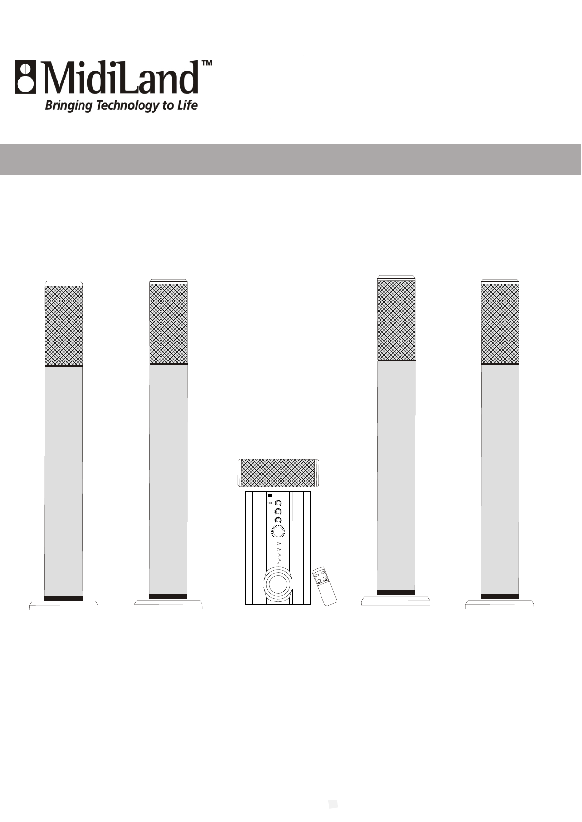
ACTIVE 5.1 HOME THEATER SURROUND SYSTEM
AC-3/dts
ACTIVE 5.1 SURROUND SYSTEM
READY
CENTER
STAND BY
MIN
MAX
WOOFER
MIN MAX
SURROUND
MIN MAX
MASTER
VOL.
MAX
MIN
AC-3
TV
TAPE
CD/VCD
DVD(2-CH)
MUTE
MLi-747H
,
Ower s Manual
MUTE
POWER
VOLUME
,
Page 2

CONTENTS
p
age
IMPORTANT SAFEGUARDSIMPORTANT SAFEGUARDS
SAFETY PRECAUTIONSAFETY PRECAUTION
IMPORTANT SAFETY INSTRUCTIONSIMPORTANT SAFETY INSTRUCTIONS
PACKING LISTPACKING LIST
PLACEMENT OF THE SPEAKERSPLACEMENT OF THE SPEAKERS
THE REMOTE CONTROLTHE REMOTE CONTROL
DESCRIPTION OF THE FRONT PANEL OF THE SUBWOOFERDESCRIPTION OF THE FRONT PANEL OF THE SUBWOOFER
3
5
5
6
6
7
7
DESCRIPTION OF THE REAR PANEL OF THE SUBWOOFERDESCRIPTION OF THE REAR PANEL OF THE SUBWOOFER
CONNECTIONSCONNECTIONS
OPERATIONOPERATION
BATTERY INSTALLATIONBATTERY INSTALLATION
IMPORTANT NOTESIMPORTANT NOTES
SPECIFICATIONSSPECIFICATIONS
22
8
9
10
10
10
11
Page 3
IMPORTANT SAFEGUARDSIMPORTANT SAFEGUARDS
1. Read Instructions - All the safety and operating
instruction should be read before the product is
operated.
2. Retain Instructions - The safety and operating
instruction should be retained for future
reference.
3. Heed Warnings - All warning on the product and
in the operating instructions should be adhered to.
4. Follow instructions - All operating and use
instructions should be followed.
5. Cleaning - Unplug this product from the wall
outlet before cleaning. Do not use liquid cleaners
or aerosol cleaners. Use a damp cloth for cleaning.
6. Attachments - Do not use attachments not
recommended by the product manufacturer as
they may cause hazards.
7. Water and Moisture - Do not use this product near
water - for example, near a bath tub, wash bowl,
kitchen sink, or laundry tub; in a wet basement, or
near a swimming pool, and the like.
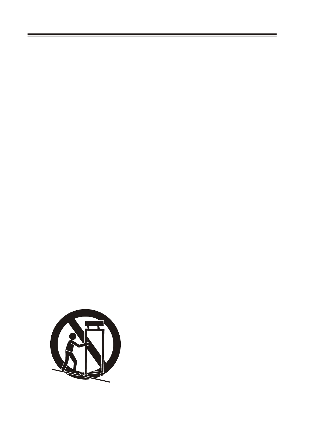
8. Accessories - Do not place this product on an
unstable cart, stand tripod, bracket, or table. The
product may fall, causing serious injury to a child
or adult, and serious damage to the product. Use
only with a cart, stand, tripod, bracket, or table
recommended by the manufacturer, or sold with
the product. Any mounting of the product should
follow the manufacturer s instructions, and
should use a mounting accessory recommended
by the manufacturer.
9. A product and cart combination should be moved
with care. Quick stops, excessive force, and
uneven surfaces may cause the appliance and cart
combination to overturn.
,
10. Ventilation - Slots and openings in the cabinet are
provided for ventilation and to ensure reliable
operation of the product and to protect it from
overheating, and these openings must not be
blocked or covered. The openings should never
be blocked by placing the product on a bed, sofa,
rug, or other similar surface. This product should
not be placed in a built - in installation such as a
bookcase or rack unless proper ventilation is
provided or the manufacturer s instruction have
been adhered to.
11. Power Sources - This product should be operated
only from the type of power source indicated on
the marking label. If you are not sure of the type
of power supply to your home, consult your
product dealer or local power company. For
products intended to operate from battery power,
or other sources, refer to the operating
instruction.
12. Grounding or Polarization - This product may be
equipped with a polarized alternating current line
plug (a plug having one blade wider than the
other). This plug will fit into the power outlet
only one way. This is a safety feature. If you are
unable to insert the plug fully into the outlet, try
reversing the plug, If the plug should still fail to
fit, contact your electrician to replace your
obsolete outlet. Do not defeat the safety purpose
of the polarizes plug.
13. Alternate Warnings - This product is equipped
with a three- wire grounding - type plug, a plug
having a third (grounding) pin. This plug will
only fit into a grounding - type power outlet. This
is a safety feature. If you are unable to insert the
plug into the outlet, contact your electrician to
replace your obsolete outlet. Do not defeat the
safety purpose of the grounding - type plug.
Power - Cord protection - Power supply cords
should be routed so that they are not likely to be
walked on or pinched by items placed upon or
against them, paying particular attention to cords
at plugs, convenience receptacles, and point
where they exit from the product.
14. Protective Attachment Plug - The product is
equipped with an attachment plug having
overload protection. This is a safety feature. See
Instruction Manual for replacement or resetting
of protective device. If replacement of the plug is
required, be sure the service technician has used
a replacement plug specified by the manufacturer
that has the same overload protection as the
original plug.
33
Page 4
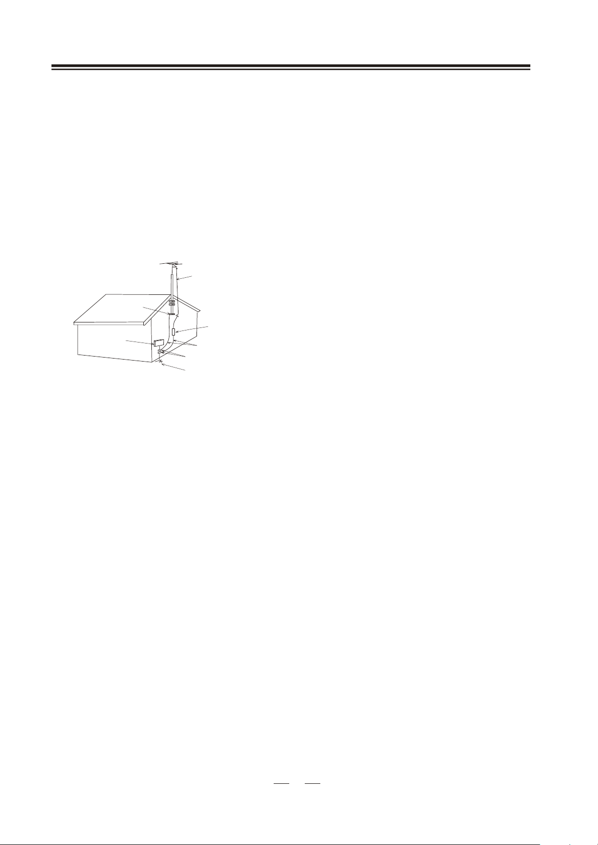
15. Outdoor Antenna Grounding - If an outside antenna
is connected to the receiver, be sure the antenna
system is grounded so as to provide some protection
against voltage surges and built - up static charges.
Article 810 of the National Electrical Code,
ANSI/NFPA 70, provides information with regard
to proper grounding of the mast and supporting
structure, grounding of the mast and supporting
structure, grounding of the lead - in wire to an
antenna - discharge unit, size of grounding
conductors, location of antenna - discharge unit,
connection to grounding electrodes, and requirements
for the grounding electrode.
See figure:
ANTENNA
LEAD IN WIRE
GROUND
CLAMP
ANTENNA
DISCHARGE UIET
ELECTRIC
SERVICE
EQUiPMENT
(NEC SECTION 810-20)
GROUNDING CONDUCTORS
(NEC SECTION 810-21)
GROUND CLAMPS
POWER SERVICE GROUNDING
ELECTRODE SYSTEM
(NEC ART 250.PART H)
16. Lightning-For added protection for this product
during a lightning storm, or when it is left
unattended and unused for long periods of time,
unplug it from the wall outlet and disconnect the
antenna or cable system. This will prevent damage
to the product due to lightning and power-line surges.
17. Power Lines-An outside antenna system should not
be located in the vicinity of overhead power lines
or other electric light or power circuits, or where it
can fall into such power lines or circuits. When
installing an outside antenna system, extreme care
should be taken to keep from touching such power
lines or circuits as contact with them might be fatal.
18. Overloading - Do not overload wall outlets,
extension cords, or integral convenience receptacles
as this can result in a risk of fire or electric shock.
20. Servicing - Do not attempt to service this product
yourself as opening or removing covers may expose
you to dangerous voltage or other hazards. Refer all
servicing to qualified service personnel.
21. Damage Requiring Service - Unplug this product
from the wall outlet and refer servicing to qualified
service personnel under the following conditions:
a) When the power- supply cord or plug is
damaged.
b) If liquid has been spilled, or objects have fallen
into the product.
c) If the product has been exposed to rain or water.
d) If the product does not operate normally by
following the operating instructions. Adjust
only those controls that are covered by the
operating instructions as an improper
adjustment of other controls may result in
damage and will often require extensive work
by a qualified technician to restore the product
to its normal operation.
e) If the product has been dropped or damaged in
any way, and.
f) When the product exhibits a distinct change in
performance - this indicates a need for service.
22. Replacement parts - When replacement parts are
required, be sure the service technician has used
replacement parts specified by the manufacturer
or have the same characteristics as the original
part. Unauthorized substitutions may result in fire,
electric shock, or other hazards.
23. Safety Check -Upon completion of any service or
repairs to this product, ask the service technician to
perform safety checks to determine that the product
is in proper operating condition.
24. Wall or Ceiling Mounting - The product should be
mounted to a wall or ceiling only as recommended
by the manufacturer.
25. Heat - The product should be situated away from
heat sources such as radiators, heat registers, stoves,
or other products (including amplifiers) that Produce
heat.
19. Object and Liquid Entry-Never push objects of any
kind into this product through openings as they may
touch dangerous voltage points or short-out parts
that could result in a fire or electric shock. Never
spill liquid of any kind on the product.
44
Page 5
SAFETY PRECAUTIONSAFETY PRECAUTION
RISK OF ELECTRIC SHOCK
DO NOT OPEN
CAUTION:TO REDUCE THE RISK OF ELECTRIC SHOCK
DO NOT REMOVE COVER (OR BACK)
NO USER-SERVICEABLE PARTS INSIDE
REFER SERVICING TO QUALIFIED SERVICE PERSONNEL.
WARNING
To prevent fire or shock hazard, do not expose the
unit to rain or moisture.
*Note: This product is for indoor use only.
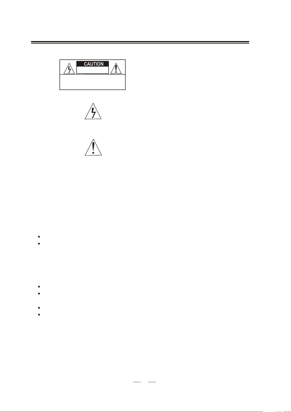
The lightning flash with arrowhead symbol ,within an
equilateral triangle, is intended to alert the user to the
presence of uninsulated "dangerous voltage"within
the product's enclosure that may be of sufficient
magnitude to constitute a r isk o f e lectric s hock to
persons.
The exclamation point within an equilateral triangle
is intended to alert the user to the presence of
important operating and maintenance (servicing)
instructions in the literature accompanying the
product.
IMPORTANT SAFETY INSTRUCTIONSIMPORTANT SAFETY INSTRUCTIONS
1. Save the user's manual
The user's manual should be saved and kept on hand as a convenient reference.
2. Cleaning the unit
Disconnect the mains plug from the outlet before attempting to clean the unit.
Do not use harsh abrasives or chemicals to clean it, as it will damage the surface finish.
Use only a soft and damp cloth.
3. Accessories
Please use the accessories enclosed in the unit. Damage caused by using non-recommended or
non-provided accessories would not be warranted.
4. P lacement
Do not use this unit near water.
Do not allow anything to drop into the subwoofer case through its ventilator, as it could result
in fatal electric shock or fire.
Place the unit far enough from other equipments for good heat dissipation.
Place the unit on a stable surface and out of reach of children to avoid damage to the unit or the
risk of injury to people.
5. Maintenance
To avoid shock hazard or damage to the unit, do not attempt to remove the cover or the rear panel.
All servicing should be referred to qualified service personnel.
55
Page 6
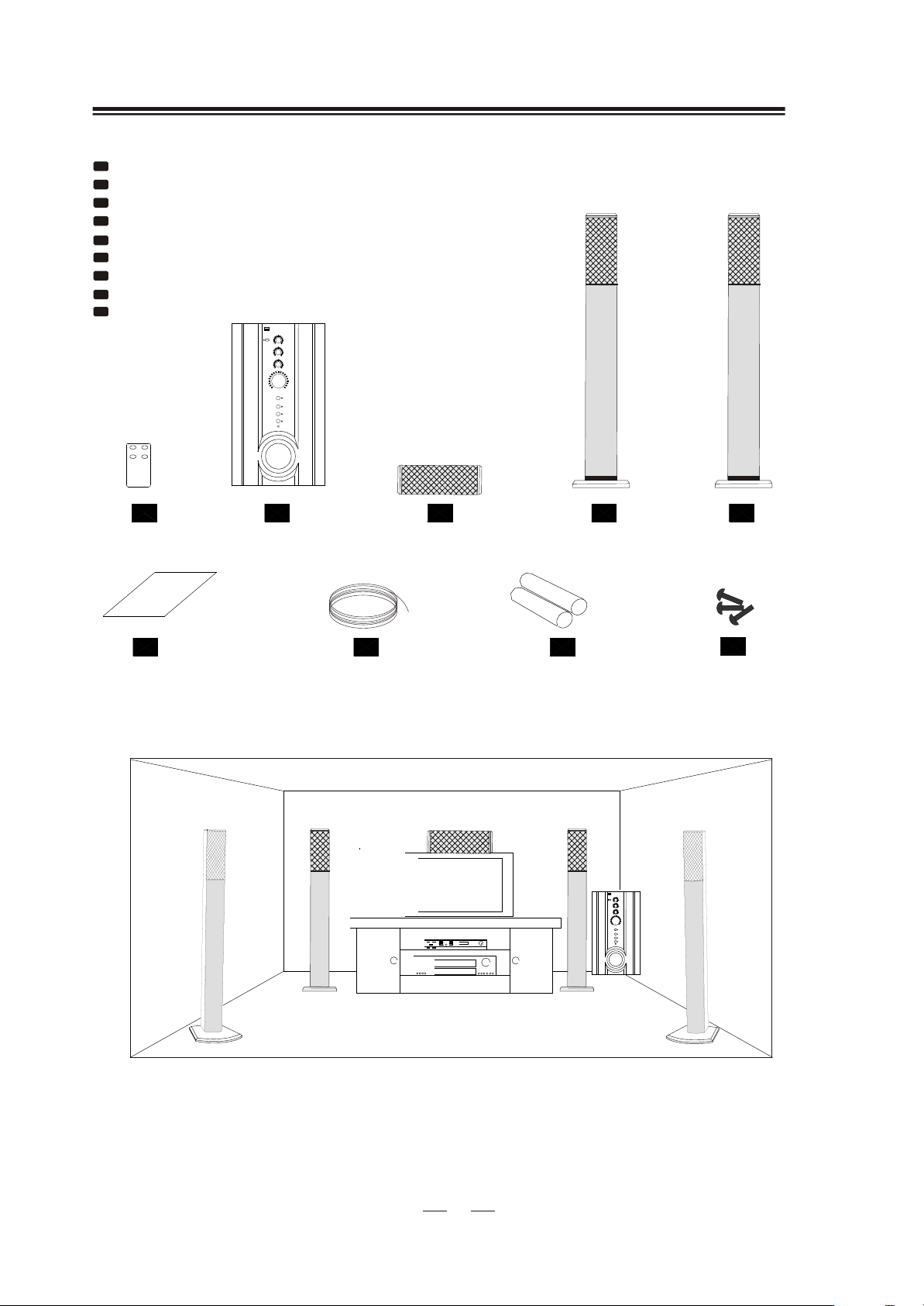
PACKING LISTPACKING LIST
1
Remote Control
2
Subwoofer speaker
3
Center Speaker
4
Front Speaker
5
Surround Speaker
6
7
8
9
,
Owner’s Manual
Speaker Connecting Cable
Battery (AAA type)
Screw
AC-3/dts
ACTIVE 5.1 SURROUND SYSTEM
READY
STAND BY
MIN
1 pc
1 pc
1 pc
2 pcs
2 pcs
1 pc
1 roll 40m
2 pcs
4x3 pcs
CENTER
MIN
MAX
WOOFER
MIN MAX
SURROUND
MIN MAX
MASTER
VOL.
MAX
AC-3
TV
TAPE
CD/VCD
DVD(2-CH)
MUTE
1
USERS MANUAL
2
3
7
PLACEMENT OF THE SPEAKERSPLACEMENT OF THE SPEAKERS
4
86
AC-3/dts
ACTIVE 5.1 SURROUND SYSTEM
READY
CENTER
STAND BY
MIN MAX
WOOFER
MIN MAX
SURROUND
MIN MAX
MASTER
VOL.
MAX
MIN
AC-3
TV
TAPE
CD/VCD
DVD(2-CH)
MUTE
5
9
66
Page 7
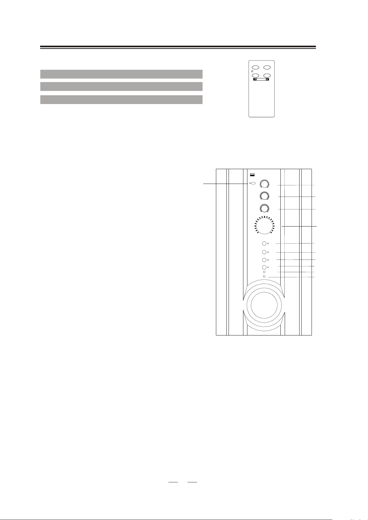
THE REMO TE CONT ROLTHE REMO TE CONT ROL
POWER
MUTE
Controls the stand by or operating mode of the system.
Turns the volume of the system on or off.
POWER
VOLUME
MUTE
VOL-, VOL+
Adjusts the volume level.
DESCRIPTION OF THE FRONT PANE L O F TH E SUBWOOFERDESCRIPTION OF THE FRONT PANE L O F TH E SUBWOOFER
1. MASTER VOLUME KNOB / POWER
INDICATOR
This knob adjusts the volume of the system.
When the power is on, the indicator light will
illuminate.
2. SURROUND VOLUME
This knob adjusts the volume of the sur-
round speakers.
3. WOOFER VOLUME
This knob adjusts the volume of the subwoofer speaker.
4. CENTER VOLUME
This knob adjusts the volume of the centre
speaker.
5. STAND-BY
Controls the stand-by or operating mode of the
system. If the indicator on the MASTER VOL.
turns red, the system is in stand-by mode; if the
indicator turns green, the system is in operating
mode.
6. AC-3 / INDICATOR
Press it to choose the AC-3(5.1) input mode.
The indicator will light.
5
ACTIVE 5.1 SURROUND SYSTEM
AC-3/dts
READY
STAND BY
MIN MAX
MIN MAX
MIN MAX
MIN
CENTER
WOOFER
SURROUND
AC-3
TV
TAPE
CD/VCD
DVD(2-CH)
MUTE
MASTER
VOL.
MAX
4
3
2
1
6
7
8
9
10
11
7. TV / INDICATOR
Press it to choose the TV input mode. The
indicator will light.
8. TAPE / INDICATOR
Press it to choose the TAPE input mode. The
indicator will light.
9. CD/VCD/DVD(2-CH) / INDICATOR
Press it to choose the CD/VCD/DVD(2-CH)
input mode. The indicator will light.
10. MUTE / INDICATOR
11. SENSOR FOR REMOTE CONTROL
77
Page 8
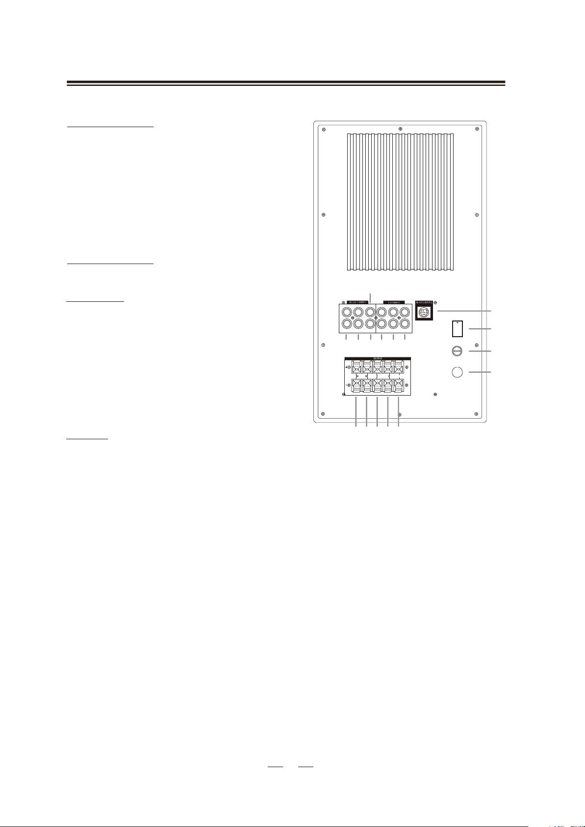
DESCRIPTION OF THE REAR PANEL OF THE SUBWOOFERDESCRIPTION OF THE REAR PANEL OF THE SUBWOOFER
AC-3 (5.1) INPUT 1
1. FRONT INPUT R/L
Front channel input connectors of the system.
2. SURROUND INPUT R/L
Surround channel input connectors of the
system.
3. CEN INPUT
Center channel input connector.
4. SUB INPUT
Subwoofer channel input connector.
AC-3 (5.1) INPUT 2
5. 9-PIN DIN CONNECTOR INPUT
2-CH INPUT
6. TV INPUT (R/L)
These connectors are used to receive the TV
or set-top box signal.
7. TAPE INPUT (R/L)
These connectors are used to receive the tape
signal.
8. CD/VCD/DVD INPUT(R/L)
These connectors are used to receive the signal
from a CD/VCD/DVD(2-CH)player.
OUTPUT
9. FRONT-R (+/-)
Front-right channel output connectors.
10. FRONT-L (+/-)
Front-left channel output connectors.
11. SURROUND-R (+/-)
Surround-right channel output connectors.
12. SURROUND-L (+/-)
Surround-left channel output connectors.
13. CEN (+/-)
Center channel output connectors.
4
SUB
R
L
FRONT
CEN TV TAPE
SURROUND
123678
FRONT
SURROUND CEN
R L R L
9 10 11 12 13
DVD(2-CH)
R
L
CD/VCD
POWER
FUSE
5
ON
14
OFF
15
AC IN
16
14. POWER
This turns the power of the system on/off.
15. FUSE
This is an easy to replace external fuse(with
rating 2.5A) to guard against unstable voltage
or current.
16. AC IN
AC power cord.
88
Page 9
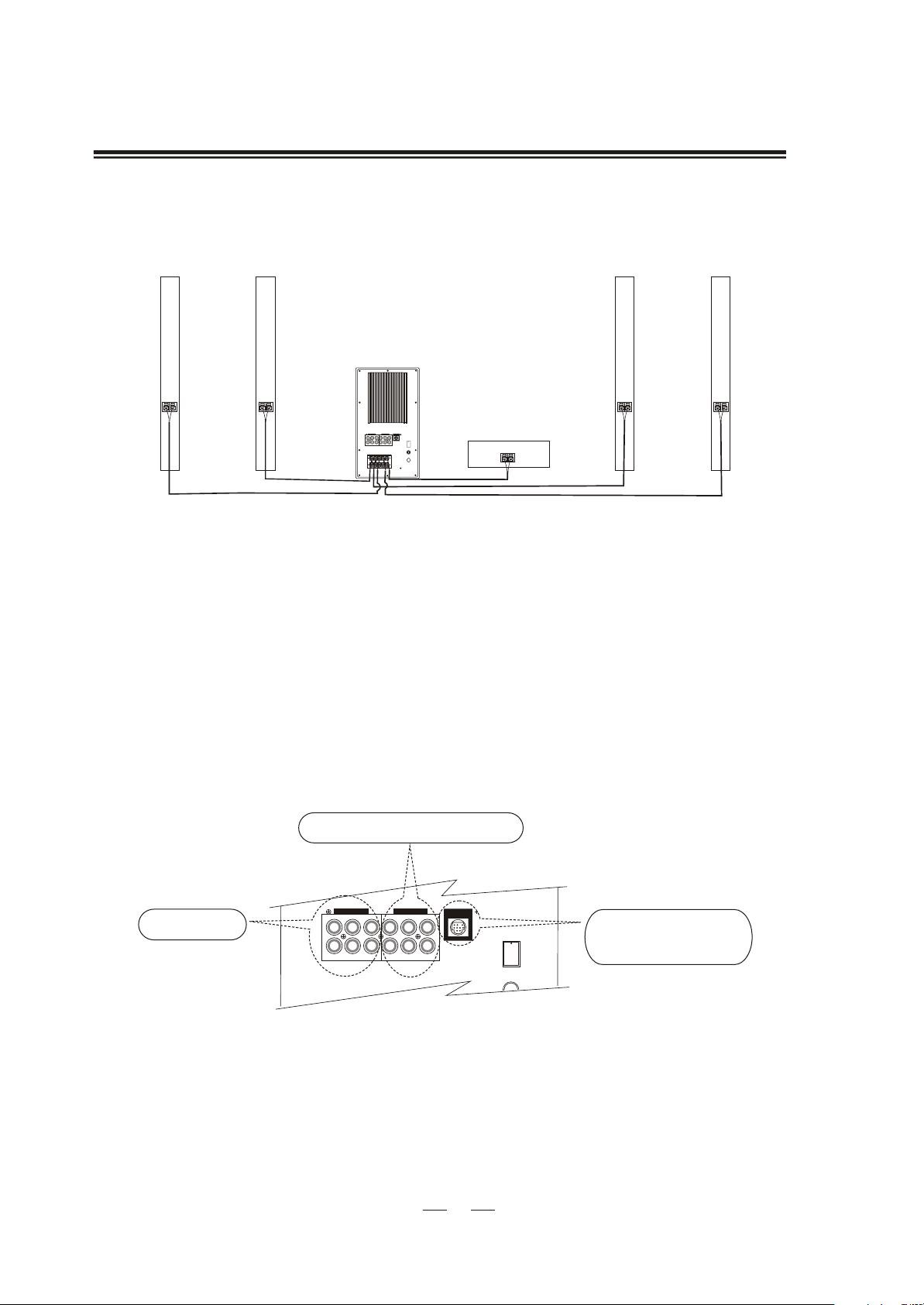
CONNECTIONSCONNECTIONS
* To prevent malfunction and/or damage to speakers or other devices, always turn down the volume,
and turn off the power on all devices before making any connections.
<Connections of the Subwoofer, the Center, the F ront and the Surround Speakers>
FL
SL
FL
SL
SUB
SUB
R
R
POWER
ON
L
L
CD/VCD
FRONT
SURROUND
CEN TV TAPE
DVD(2-CH)
OFF
FUSE
AC IN
FRONT
SURROUND CEN
L
R
R L
CEN
1. Connect the FR speaker to the OUTPUT-FRONT(R) spring tags of the subwoofer -- the striped
wire to the red positive terminal and the NON-STRIPED wire to the BLACK negative terminal.
2. Connect the FL speaker to the OUTPUT-FRONT(L) spring tags of the subwoofer -- the striped
wire to the red positive terminal and the NON-STRIPED wire to the BLACK negative terminal.
3. Connect the SR s peaker t ot he O UTPUT-SURROUND(R) s p ring ta gs of the sub woofer -- t he str iped
wire to the red positive terminal and the NON-STRIPED wire to the BLACK negative terminal.
4. Connect the SL s peaker t o t he O UTPUT-SURROUND(L) sp ring ta gs of the sub woofer-- t he str iped
wire to the red positive terminal and the NON-STRIPED wire to the BLACK negative terminal.
5. Connect the CEN s peaker t o t he O UTPUT-CEN s p ring ta gs of th e su bwoofer -- th e st ripe d wire
to the red positive terminal and the NON-STRIPED wire to the BLACK negative terminal.
<Connections of the subwoofer and the audio source>
To CD / VCD / TV / TAPE PLAYER
To D VD
AC-3 (5.1) INPUT 1
R
L
FRONT
SURROUND CEN TV TAPE
SUB
2-CH INPUT
DVD(2-CH)
AC-3 (5.1) INPUT 2
R
L
CD/VCD
POWER
ON
OFF
FUSE
To an AC-3 (5.1) Audio
Source with a 9-pin Din
Connector
The AC-3 (5.1) INPUT 1 connectors on the subwoofer are used fo r connecting a 5.1 ch annel device with
separate front,
surround, centre and subwoofer outputs s uch as a DVD player.
The AC-3 (5.1) INPUT 2 connector on t he s ubwoofer i s used for connecting a 5.1 ch annel device with its
output on a 9-pin DIN connector
s uch as a computer soundcard.
The three input connections marked as 2-CH INPUT are used for connecting up to three 2-channel (stereo)
devices, such as a TV, digital set-top box,CD player, radio tuner, tape player or any audio device offering a
LINE-OUT audio connection.
99
Page 10
OPERATIONOPERATION
1. Press down the tip of the POWER rocker switch with a white "1" on the back of the subwoofer to
turn on the system. The system is then se t in STAND-B Y mod e an d t he indicato r ligh t o n the
MASTER VOL. knob on the front panel w ill t urn r ed .
2 . P r e s s t h e POWER button on the remote control or the STAND-BY button on the front panel
of the subwoofer once, and the system will switch to OPERATING mode and the indicator light
on the
3. Press the AC-3, TV, TAPE or the CD/VCD/DVD(2-CH) button to choose the right source of audio
input mode, and its corresponding indicator light will turn green.
4. Rotate the following knobs on the front panel of the subwoofer clockwise to a suitable listening
level:
a) CENTER
b) WOOFER
c) SURROUND
d) MASTER VOL.
Or, press the VOLU ME UP and VOLUME DOWN buttons on the remote control to adjust
the volume level of the system:
a)press the VOLUME UP button, andt he M ASTER V OL. k nob o nth efr ont p anelof th esu bwoofer
will turn clockwise and the volume level of the system will be increased.
b) press the VOLUME DOWN button, a nd t he M ASTER V OL. k nob o n t he f ront p anel o f th e s ub-
woofer will turn counterclockwise a nd t he volume level of the systemw ill be decreased.
MASTER VOL. will turn green.
5. Press the MUTE button on the remote control once to turn off the volume of the system , and the
mute indicator light on the front panel of the subwoofer will turn green, To turn on the volume of
the system, press the MUTE button again and the mute indicator light will turn off.
*
It is recommended that the POWER rocker switch on the back of the subwoofer be turned off and
that the AC power cord be unplugged from the supply when the system is left unused for a long
period of time.
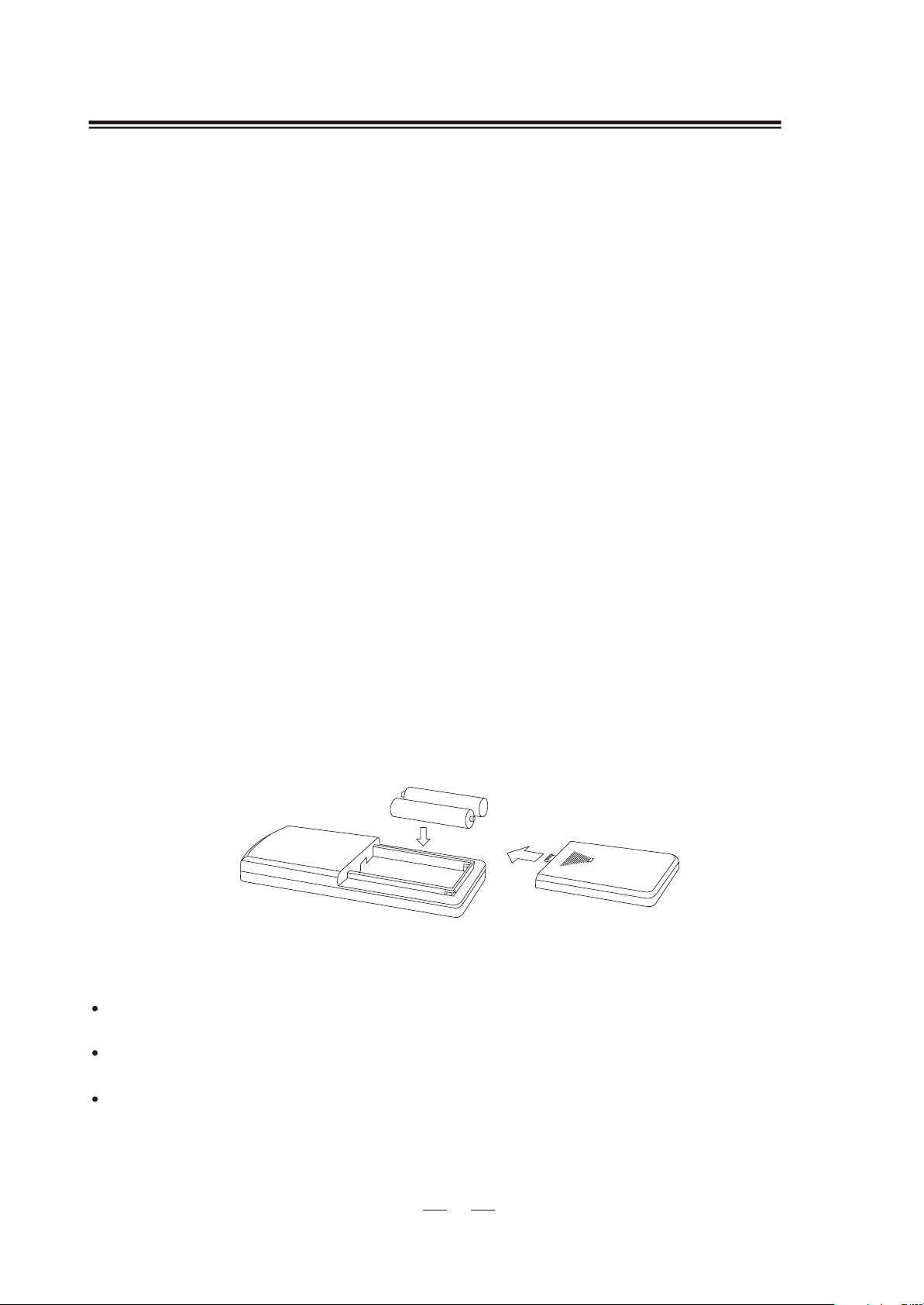
BATTERY INSTALLATIONBATTERY INSTALLATION
Batteries( AAA t ype)
IMPORTANT NOTESIMPORTANT NOTES
< AC Power >
Make sure that the power supply is correct and never handle the power cord or its plug with wet
hands when plugging into, or unplugging from, a n o utlet.
Ensure that the main power switch is in the "OFF" position before connecting the AC power cord
to the power supply to avoid damage to the system.
A damaged power cord can easily cause an electric shock or fire hazard. Neve r use a powe r cord
after it has been damaged.
1010
Page 11
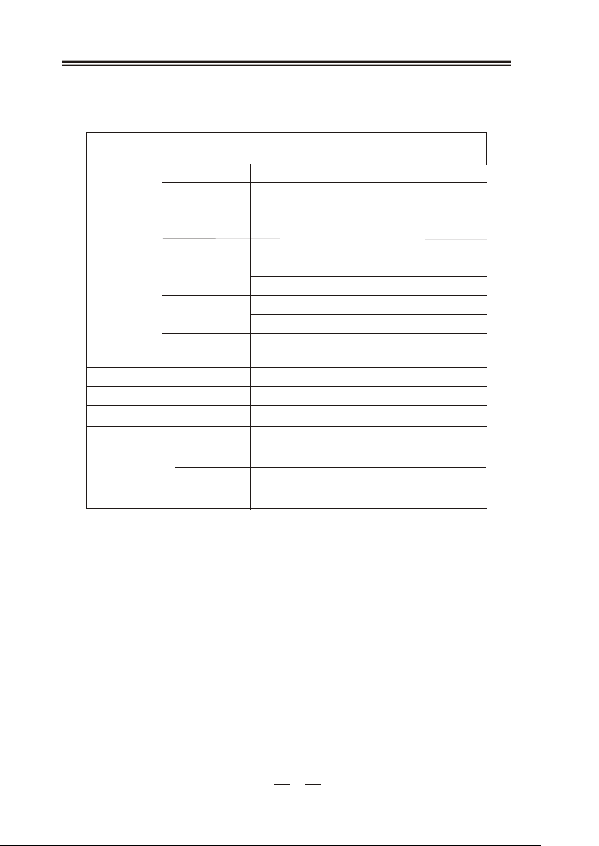
SPECIFICATIONSSPECIFICATIONS
MLi-747H
SUBWOOFER
POWER
OUTPUT
(RMS)
FRONT
CENTRE
SURROUND
SUBWOOFER
FRONT
SPEAKER
UNIT
CENTRE
SURROUND
RATED IMPEDANCE
FREQUENCY RESPONSE
S/N RATIO
SUBWOOFER
FRONT
DIMENSIONS
CENTRE
60W
20Wx 2
20W
20Wx2
WOOFER, 6 /2", 8 W
FULL RANGE, 3", 16W
TWEETER, 1"
FULL RANGE, 3", 16W
TWEETER, 1"
FULL RANGE, 3", 8 W
TWEETER, 1"
>7 KW
20 Hz ~20 KHz
>70dB
220(W) x 380(H) x 300(D) mm
90(W) x1020(H) x 105(D) mm
280(W) x 90(H) x 105(D) mm
1
SURROUND
90(W) x 1020(H) x 105(D) mm
1111
 Loading...