

Page 1
OWNER’S MANUAL
Please read this manual thoroughly
and retain it for future reference.
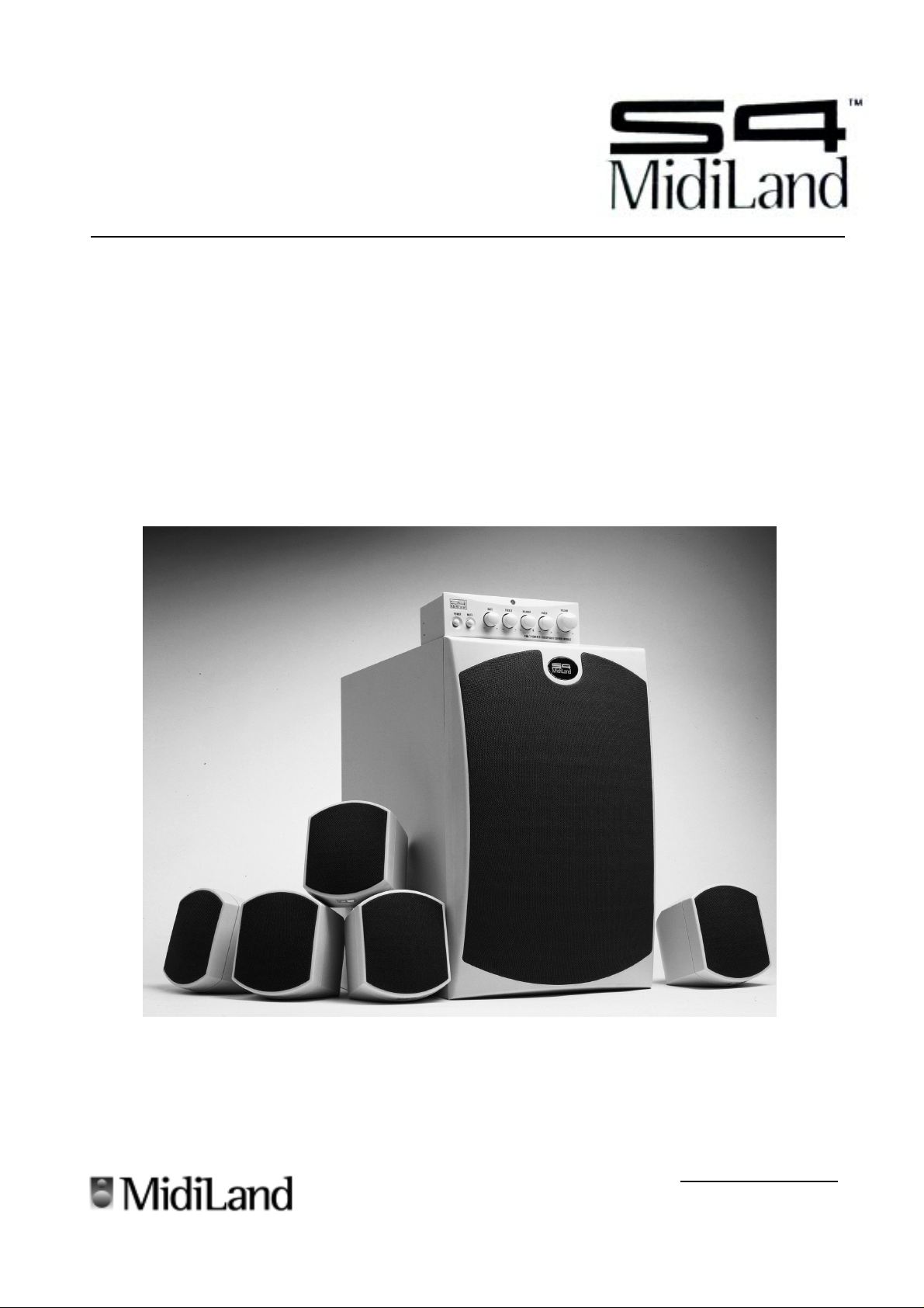
S4 MidiLand
7100/7100M
SELF-POWERED MULTIMEDIA
SPEAKER SYSTEM
© 2000 By MidiLand, Inc. All Rights Reserved.
S4 MidiLandS4 MidiLand
S4 MidiLand
S4 MidiLandS4 MidiLand
Serial #Serial #
Serial #
Serial #Serial #
The model and serial numbers are located on
the back of the subwoofer. Record the serial
number in the space above for future reference.
7100 7100
™™
™
7100
™™
7100 7100
Page 2
IMPORTANT SAFEGUARDS
4
4
4
4
4
About operating voltageAbout operating voltage
About operating voltage
About operating voltageAbout operating voltage
Operate the unit with the appropriate voltage as indicated on the
outer packaging and where power cord comes out of the AC
adapter. It will be one of the following:
•110V-120V @60 Hz • 220V-240V @50Hz
About safetyAbout safety
About safety
About safetyAbout safety
• The nameplate indicating operating voltage, power
consumption, etc…is located on the AC adapter.
• Unplug the unit from the wall outlet when it is not to be
used for an extended period of time. To disconnect the
cord, pull it out by grasping the plug, never pull it out by
the cord.
• Should any solid object or liquid fall into the unit,
disconnect the AC power cord, and have qualified service
professional check the unit before operating the unit
again.
About installationAbout installation
About installation
About installationAbout installation
• Do not place the unit near heat sources, moisture, rain or
mechanical shock, and ensure that there is nothing to
interfere with proper ventilation/airflow.
• Although the unit is magnetically/video shielded, it is
recommended that magnetically sensitive equipment such
as personal credit cards, floppy disks, TV screens,
etc…be placed as far as reasonably possible away from
the unit.
• The unit should only be used with a cart or stand that is
recommended by the manufacturer.
• The unit should be mounted to a wall or ceiling only as
recommended by the manufacturer.
TO PREVENT FIRE OR SHOCK HAZARD, DO NOT EXPOSE THE UNIT TO RAIN OR MOISTURE!TO PREVENT FIRE OR SHOCK HAZARD, DO NOT EXPOSE THE UNIT TO RAIN OR MOISTURE!
WARNING:
The “lightening bolt” symbol
is intended to alert the user to
the presence of uninsulated
“dangerous voltage” within the
product’s enclosure that may be
of electric shock to persons.
The S4 MidiLand™ 7100 High Performance Multimedia 100W RMS Powered Loudspeaker System you are about to set-The S4 MidiLand™ 7100 High Performance Multimedia 100W RMS Powered Loudspeaker System you are about to set-
The S4 MidiLand™ 7100 High Performance Multimedia 100W RMS Powered Loudspeaker System you are about to set-
The S4 MidiLand™ 7100 High Performance Multimedia 100W RMS Powered Loudspeaker System you are about to set-The S4 MidiLand™ 7100 High Performance Multimedia 100W RMS Powered Loudspeaker System you are about to setup and install is one of the finest multimedia products available today. Please locate all of the parts below before youup and install is one of the finest multimedia products available today. Please locate all of the parts below before you
up and install is one of the finest multimedia products available today. Please locate all of the parts below before you
up and install is one of the finest multimedia products available today. Please locate all of the parts below before youup and install is one of the finest multimedia products available today. Please locate all of the parts below before you
begin.begin.
begin.
begin.begin.
TO PREVENT FIRE OR SHOCK HAZARD, DO NOT EXPOSE THE UNIT TO RAIN OR MOISTURE!
TO PREVENT FIRE OR SHOCK HAZARD, DO NOT EXPOSE THE UNIT TO RAIN OR MOISTURE!TO PREVENT FIRE OR SHOCK HAZARD, DO NOT EXPOSE THE UNIT TO RAIN OR MOISTURE!
The “exclamation mark” symbol
is intended to alert the user
to the presence of important
operating and maintenance
instructions in the literature
accompanying the appliance
A VIS:
CAUTION
RISK OF ELECTRIC SHOCKRISK OF ELECTRIC SHOCK
RISK OF ELECTRIC SHOCK
RISK OF ELECTRIC SHOCKRISK OF ELECTRIC SHOCK
DO NOT OPEN!DO NOT OPEN!
DO NOT OPEN!
DO NOT OPEN!DO NOT OPEN!
RISQUE DE CHOC ELECTRIQUE NE PRISQUE DE CHOC ELECTRIQUE NE P
RISQUE DE CHOC ELECTRIQUE NE P
RISQUE DE CHOC ELECTRIQUE NE PRISQUE DE CHOC ELECTRIQUE NE P
AS OUVRIRAS OUVRIR
AS OUVRIR
AS OUVRIRAS OUVRIR
.
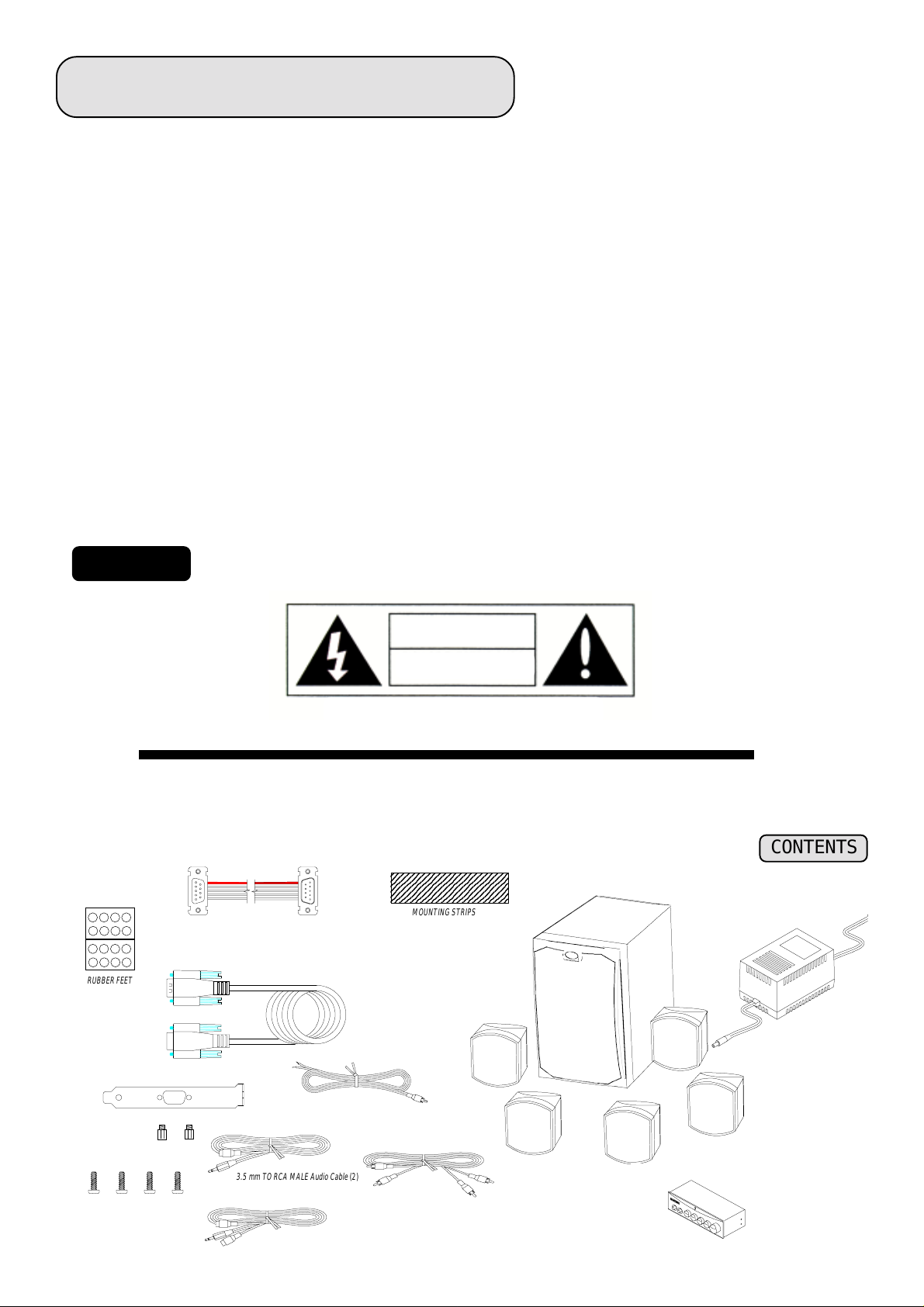
CONTENTS
2345678901234567890123
2345678901234567890123
2345678901234567890123
2345678901234567890123
2345678901234567890123
RUBBER FEET
RIBBON CABLE
INTERFACE CABLE
MOUNTING STRIPS
POWERED
SUBWOOFER
POWER TRANSFORMER
SLOT COVER
SELF-THREADING
SCREWS
SPEAKER CABLES
3.5 mm TO RCA MALE Audio Cable
3.5 mm TO RCA MALE Audio Cable
(5)
SATELLITE SPEAKERS
(2)
AUDIO CABLE
(3)
(2)
CONTROL MODULE
22
2
22
Page 3

SETUP
Check your
1
l Five (5)
l One (1)
l One (1) CM-7
l One (1) 10 Feet, 9-Pin to 9-Pin
l Two (2) 6 Feet and 8 inches, high performance Wire
l Two (2) 16 Feet, rear channel high performance
l Three (3) 10 Feet, Dual RCA to Dual RCA
l Two (2) 1.5 Feet,
l TWo (2) 1.5 Feet
l One (1) 2’ 9-pin to 9-pin flat
l Eight (8) non-marring, self-adhesive
l One (1) 4” self-adhesive control module
l Four (4)
l One (1)
Your packaging may also contain other printed material with special offers for direct purchase of related multimedia products as well as optional MidiLand™ accessories.
S4 MidiLand™ 7100S4 MidiLand™ 7100
S4 MidiLand™ 7100 package for the following items:
S4 MidiLand™ 7100S4 MidiLand™ 7100
Satellite SpeakersSatellite Speakers
Satellite Speakers.
Satellite SpeakersSatellite Speakers
SubwooferSubwoofer
Subwoofer with integrated 100W RMS power amplifier.
SubwooferSubwoofer
Control ModuleControl Module
Control Module.
Control ModuleControl Module
Interface CableInterface Cable
Interface Cable (subwoofer to CM-7 control module).
Interface CableInterface Cable
Speaker CablesSpeaker Cables
Speaker Cables.
Speaker CablesSpeaker Cables
Speaker Cables.Speaker Cables.
Speaker Cables.
Speaker Cables.Speaker Cables.
Audio Cable Audio Cable
Audio Cable .
Audio Cable Audio Cable
3.5mm Stereo Mini Jack to RCA Female Audio Cable.3.5mm Stereo Mini Jack to RCA Female Audio Cable.
3.5mm Stereo Mini Jack to RCA Female Audio Cable.
3.5mm Stereo Mini Jack to RCA Female Audio Cable.3.5mm Stereo Mini Jack to RCA Female Audio Cable.
, 3.5mm Mono Mini Jack to RCA Mono Female Audio Cable., 3.5mm Mono Mini Jack to RCA Mono Female Audio Cable.
, 3.5mm Mono Mini Jack to RCA Mono Female Audio Cable.
, 3.5mm Mono Mini Jack to RCA Mono Female Audio Cable., 3.5mm Mono Mini Jack to RCA Mono Female Audio Cable.
Ribbon CableRibbon Cable
Ribbon Cable with separate metal
Ribbon CableRibbon Cable
Rubber FeetRubber Feet
Rubber Feet.
Rubber FeetRubber Feet
Mounting StripsMounting Strips
Mounting Strips.
Mounting StripsMounting Strips
Self-threading ScrewsSelf-threading Screws
Self-threading Screws for internal mounting of control module.
Self-threading ScrewsSelf-threading Screws
Power Transformer.Power Transformer.
Power Transformer.
Power Transformer.Power Transformer.
Slot CoverSlot Cover
Slot Cover.
Slot CoverSlot Cover
Prepare the area where you will be installing your multimedia system.
2
Following are some tips you might want to consider:
Select a location for the
•
(2-3’ apart if using on a desktop with your multimedia computer, personal stereo or mini-bookshelf audio system; at least 3-4’ apart
if using fairly close to a television set with your set top video game and at least 6’-8” apart if using them in a home theater or
traditional audio setup (i.e., when listening from across the room).
Featuring a dual angle elipsoidal design, the satellite speakers may be used in either of two (2) “tilt” angles simply by turning the unit
•
“upside-down”. The angle can be 15° or 25° to help raise the stereo image and improve focus and clarity. The satellite speakers may
also be wall mounted with optional bracket available separately from your dealer.
Select a solid location for the
•
Integrated Amplifier mounted in the rear of the subwoofer enclosure. To enhance bass performance, it is generally advisable to place
the subwoofer next to a wall or solid piece of furniture with the woofer/grille side pointing away from the wall or furniture. You’ll
probably want to experiment with several different locations once you’ve completed the installation and hookup. Place 4
FeetFeet
Feet under subwoofer to protect the mounting surface, if necessary.
FeetFeet
satellite speakerssatellite speakers
satellite speakers which is solid and places them an appropriate distance apart for good stereo imaging
satellite speakerssatellite speakers
subwoofersubwoofer
subwoofer (generally on the floor) which allows adequate ventilation for the 60W RMS
subwoofersubwoofer
RubberRubber
Rubber
RubberRubber
If you choose to mount the
•
control module externally (i.e. the underside of your desktop, underneath your monitor, on top of your desktop, etc.), we have supplied
self-adhesive mounting strips or 4
control modulecontrol module
control module internal to a computer, refer to
control modulecontrol module
Rubber FeetRubber Feet
Rubber Feet to secure/place the controls wherever it is most convenient.
Rubber FeetRubber Feet
illustration I-1illustration I-1
illustration I-1. However, if you choose to mount the
illustration I-1illustration I-1
33
3
33
Page 4

FEATURES
• 100 WATT RMS INTEGRATED POWER AMPLIFIER
• 6½” (165mm) SUBWOOFER
• 2½” (65mm) WIDEBAND SATELLITE SPEAKERS
• INTERNAL/EXTERNAL REMOTE CONTROL MODULE
• 5.1 MULTI-CHANNEL
• EXTERNAL LOW-NOISE POWER TRANSFORMER
CONNECTIONS
With the power switch in the off position and the power transformer plug not connected,
3
refer to the instructions and illustrations below.
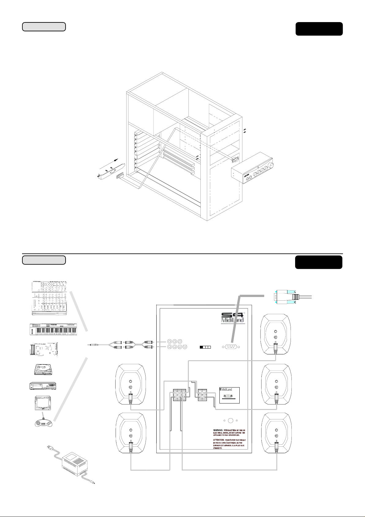
Locate the 10’ 9-pin to 9-pin
•
located at the rear of the subwoofer unit and the other end to rear of the
interface cable interface cable
interface cable, plug one end of the 9-pin CM-7 interface connector to the subwoofer’s amplifier
interface cable interface cable
l COMPLETE MAGNETIC/VIDEO SHIELDING
l SMALL DESKTOP “FOOTPRINT”
l DYNAMIC SOUND QUALITY
l PATENT PENDING CM-7 INTERFACE
l DOLBY DIGITAL READY
CM-7 control moduleCM-7 control module
CM-7 control module. If you have chosen to mount
CM-7 control moduleCM-7 control module
the control module internal to a computer, than you must locate the 2’ 9-pin to 9-pin ribbon cable and refer to
Using the supplied
•
subwoofer amplifier’s
the output to the correspondent speaker and the type of connection. Refer to
In the package please locate a 1.5’ dual RCA to stereo
•
computer’s sound card, a portable CD player, or wherever a source with a 3.5mm jack is required to one of the amplifier’s RCA
inputs. If another type of connector is required, please check with your sound appliance vendor for the adaptor you may need.
Using this 1.5’ cable, simply plug the
The
red color RCA plug should be connected to the “right” input and the white color RCA to the “left” input. See to the specifications section for further details. Refer to
SOUND SOURCE CONNECTION.”SOUND SOURCE CONNECTION.”
SOUND SOURCE CONNECTION.”
SOUND SOURCE CONNECTION.”SOUND SOURCE CONNECTION.”
Power is supplied to the
•
supplied for the territory you purchased the unit in. First, make sure to connect the coaxial power plug into the labeled power
receptacle on the rear of the subwoofer. Second, connect the country specific corded plug into an approved and properly function-
speaker cable speaker cable
speaker cable connect the front left, front right, rear left, rear right and center satellite speakers to the
speaker cable speaker cable
outputoutput
output. The connection terminals are simple plug-in type, needing only to be concerned with connecting
outputoutput
illustration I-2illustration I-2
illustration I-2.
illustration I-2illustration I-2
3.5 mm stereo jack cable 3.5 mm stereo jack cable
3.5 mm stereo jack cable. This cable is intended to connect a
3.5 mm stereo jack cable 3.5 mm stereo jack cable
RCARCA
RCA end into the
RCARCA
illustration I-2 to I-6 for your ”SPECIFICillustration I-2 to I-6 for your ”SPECIFIC
illustration I-2 to I-6 for your ”SPECIFIC
illustration I-2 to I-6 for your ”SPECIFICillustration I-2 to I-6 for your ”SPECIFIC
S4 MidiLand™ 7100 S4 MidiLand™ 7100
S4 MidiLand™ 7100 via a supplied external
S4 MidiLand™ 7100 S4 MidiLand™ 7100
Audio Cable Audio Cable
Audio Cable and connect the
Audio Cable Audio Cable
Power TransformerPower Transformer
Power Transformer. The correct voltage adapter is
Power TransformerPower Transformer
RCA plugsRCA plugs
RCA plugs into the amplifier’s
RCA plugsRCA plugs
illustration I-1illustration I-1
illustration I-1.
illustration I-1illustration I-1
input input
input.
input input
ing AC wall outlet.
pushed in on the control module.
DO NOTDO NOT
DO NOT use an extension cord or an overly crowded wall plate. Third, make sure the power button is
DO NOTDO NOT
44
4
44
Page 5
APPLICATIONS
CONTROL MODULE
INTERNAL MOUNTING
Illustration I-1Illustration I-1
Illustration I-1
Illustration I-1Illustration I-1
* Please note that the control
module may not fit into all computers. You may need to purchase “rails” or other adapters from the maker of your
computer.
SLOT COVER
RIBBON CABLE
*TYPICAL COMPUTER
SELF-THREADING
SCREWS
CONTROL MODULE
APPLICATIONSAPPLICATIONS
APPLICATIONS
APPLICATIONSAPPLICATIONS
Keyboard/MIDI/Mixer/PA
Computer/Sound Card
Portable stereo
CD/Laser Disc/VCR/TV/DVD
Game
Video Games
TO SOUND SOURCE OUTPUT
Sound Source: StereoSound Source: Stereo
Sound Source: Stereo
Sound Source: StereoSound Source: Stereo
Input
F/R R/R SUB
F/L R/L C SURR
Switch
Position
Output
F/R F/L C R/RR/L
+
_
S4 MidiLand 4060
+
_
S/N:
MIDILAND, INC.
SEE INSTRUCTI ON M ANUAL
S4 BUS
REMOTE
CONTROL
Speaker System
Power In
MADE IN CHINA
Illustration I-2Illustration I-2
Illustration I-2
Illustration I-2Illustration I-2
SUBWOOFER-REAR VIEW
Interface Cable
Power Transformer
55
5
55
Page 6
APPLICATIONSAPPLICATIONS
APPLICATIONS
APPLICATIONSAPPLICATIONS
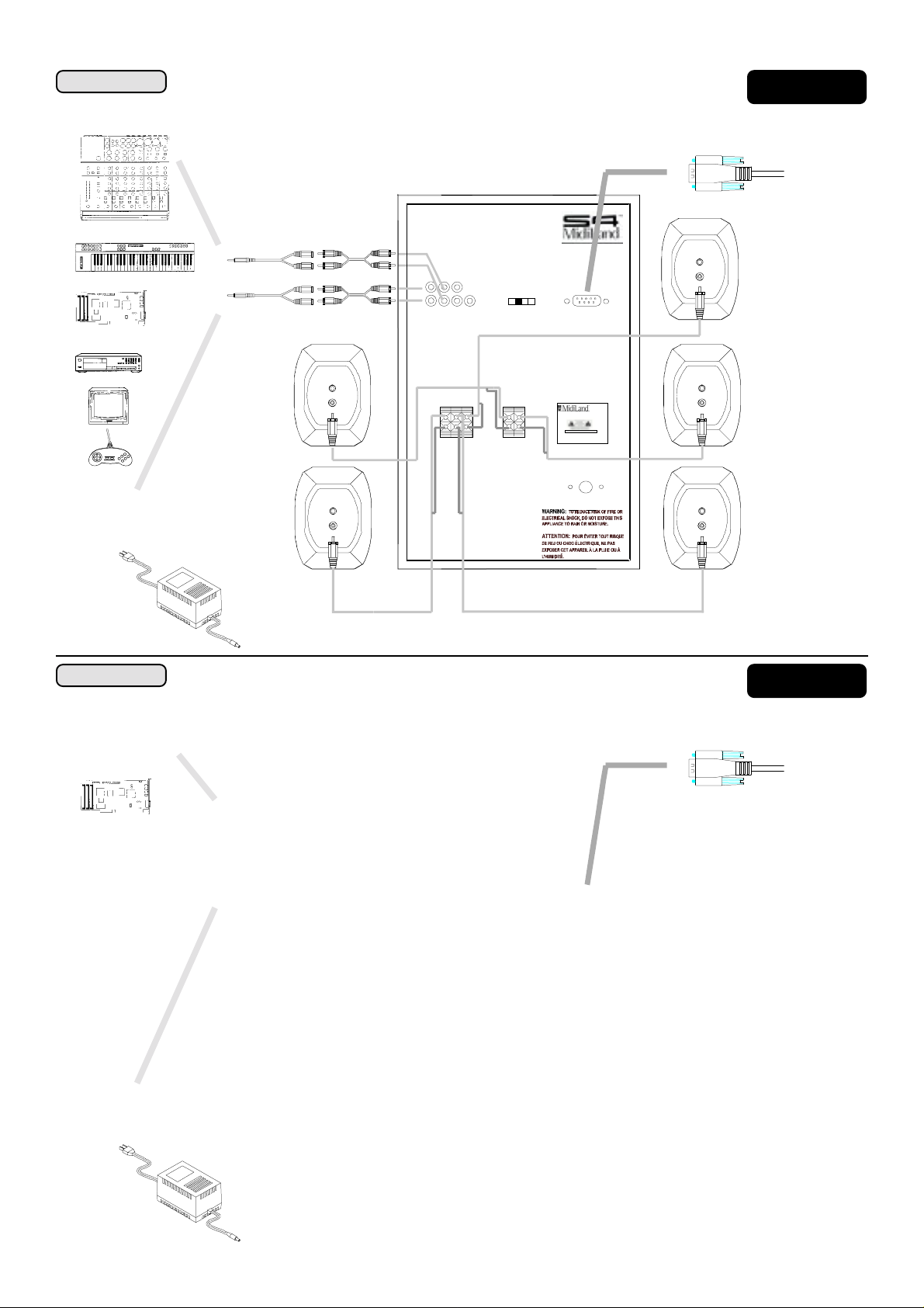
Keyboard/MIDI/Mixer/PA
Computer/Sound Card
TO SOUND SOURCE OUTPUT
Sound Source: 4.1 ChannelSound Source: 4.1 Channel
Sound Source: 4.1 Channel
Sound Source: 4.1 ChannelSound Source: 4.1 Channel
Input
F/R R/R SUB
F/L R/L C SURR
Switch
Position
S4 BUS
REMOTE
CONTROL
Illustration I-3Illustration I-3
Illustration I-3
Illustration I-3Illustration I-3
SUBWOOFER-REAR VIEW
Interface Cable
CD/Laser Disc/VCR/TV/DVD
Game
Video Games
APPLICATIONSAPPLICATIONS
APPLICATIONS
APPLICATIONSAPPLICATIONS
Computer/Sound Card
Power Transformer
TO SOUND SOURCE OUTPUT
Output
F/R F/L C R/RR/L
+
_
Sound Source: 5.1 ChannelSound Source: 5.1 Channel
Sound Source: 5.1 Channel
Sound Source: 5.1 ChannelSound Source: 5.1 Channel
+
_
S4 MidiLand 4060
S/N:
MIDILAND, INC.
SEE INSTRUCTI ON M ANUAL
Power In
Speaker System
MADE IN CHINA
Illustration I-4Illustration I-4
Illustration I-4
Illustration I-4Illustration I-4
SUBWOOFER-REAR VIEW
Interface Cable
Power Transformer
Input
F/R R/R SUB
F/L R/L C SURR
Output
F/R F/L C
Switch
Position
R/RR/L
S4 BUS
REMOTE
CONTROL
Power In
66
6
66
Page 7
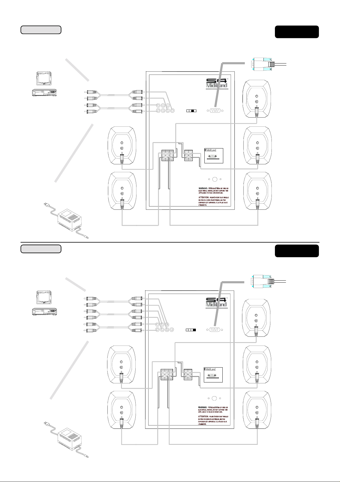
APPLICATIONSAPPLICATIONS
APPLICATIONS
APPLICATIONSAPPLICATIONS
Sound Source: Dolby Pro LogicSound Source: Dolby Pro Logic
Sound Source: Dolby Pro Logic
Sound Source: Dolby Pro LogicSound Source: Dolby Pro Logic
Illustration I-5Illustration I-5
Illustration I-5
Illustration I-5Illustration I-5
SUBWOOFER-REAR VIEW
CD/Laser Disc/TV/DVD
TO SOUND SOURCE OUTPUT
Power Transformer
Input
F/R R/R SUB
F/L R/L C SURR
Output
F/R F/L C R/RR/L
Interface Cable
Switch
Position
+
_
S4 BUS
REMOTE
CONTROL
Speaker System
S4 MidiLand 4060
+
_
S/N:
MIDILAND, INC.
SEE INSTRUCTI ON M ANUAL
MADE IN CHINA
Power In
APPLICATIONSAPPLICATIONS
APPLICATIONS
APPLICATIONSAPPLICATIONS
CD/Laser Disc/TV/DVD
TO SOUND SOURCE OUTPUT
Sound Source: Dolby DigitalSound Source: Dolby Digital
Sound Source: Dolby Digital
Sound Source: Dolby DigitalSound Source: Dolby Digital
Input
F/R R/R SUB
F/L R/L C SURR
Switch
Position
S4 BUS
REMOTE
CONTROL
Output
F/R F/L C
R/RR/L
+
_
+
_
S4 MidiLand 4060
S/N:
MIDILAND, INC.
SEE INSTRUCTI ON M ANUAL
Power In
Speaker System
MADE IN CHINA
Illustration I-6Illustration I-6
Illustration I-6
Illustration I-6Illustration I-6
SUBWOOFER-REAR VIEW
Interface Cable
Power Transformerr
77
7
77
Page 8

HOW TO USE
After verifying that everything has been connected properly, plug the power cord into an available AC wall outlet.
4
On the control module, set the controls as follows:
l Turn on the system with the
l Rotate the
l Press the
l Turn the
To start making music, adjust the controls as follows:
5
l Start your music, CD-ROM, movie, or other sound source playing and turn up its output level, if available.
l Rotate the
l Adjust the
l Rotate the
l Rotate the
l Make sure to experiment with all of the controls to customize the sound just the way you like it. If you have a question,
look in to the
l For further support e-mail us at [email protected] or call Customer Service at (888) 592-1168 or call your local
Midiland Authorized dealer.
Volume Volume
Volume control fully couterclockwise.
Volume Volume
MuteMute
Mute buttons so that they are in the out position, not “engaged”.
MuteMute
BassBass
Fade,TrebleFade,Treble
Bass,
Fade,Treble, and
BassBass
Fade,TrebleFade,Treble
VV
olumeolume
V
olume control clockwise to the desired listening level.
VV
olumeolume
BalanceBalance
Balance control left and right to audibly check your connections.
BalanceBalance
BassBass
Bass and
BassBass
FadeFade
Fade control left and right to adjust front and rear sound separation.
FadeFade
TroubleshootingTroubleshooting
Troubleshooting page.
TroubleshootingTroubleshooting
POWERPOWER
POWER button.
POWERPOWER
BalanceBalance
Balance to the center detent position, “12 o’clock”.
BalanceBalance
TrebleTreble
Treble left and right. You should noticably hear an increase or decrease in tone.
TrebleTreble
88
8
88
Page 9
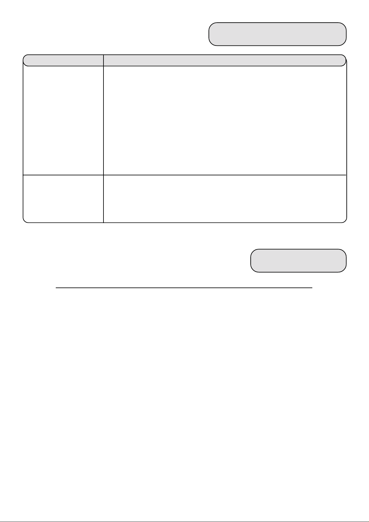
TROUBLESHOOTING
PROBLEM
No sound at allNo sound at all
No sound at all
No sound at allNo sound at all
Only one channel isOnly one channel is
Only one channel is
Only one channel isOnly one channel is
workingworking
working
workingworking
For further information or support, e-mail us at [email protected] or call Customer Service at (888)592-1168.
POSSIBLE SOLUTION
Verify that the system is plugged into a wall outlet and that the outlet is not switched to the “off”
position.
Make sure that the amplifier’s
CM-7 LED is illuminated.
Turn the
Turn the output level from your sound source up.
Make sure the
Check that the
Make sure that there are no loose speaker cable connections. The speaker cable plug must be firmly
seated in the proper jack on the rear side of the satellite and amplifier.
volumevolume
volume on the control module up.
volumevolume
mutemute
mute botton is not engaged.
mutemute
balance balance
balance and
balance balance
powerpower
power switch is pushed in on the Control Module and that the green
powerpower
fade fade
fade controls are centered and that the input connections are OK.
fade fade
WARRANTY
Three Years Limited WarrantyThree Years Limited Warranty
Three Years Limited Warranty
Three Years Limited WarrantyThree Years Limited Warranty
MidiLand, Inc. warrants to the end user that all of its computer speakers are free from defects in materials and
workmanship in the course of normal and reasonable use for a term of three (3) years from the date of purchase.
This warranty is the exclusive and only warranty in effect relative to MidiLand, Inc. computer speaker systems
and any other warranties, either expressed or implied, are invalid. Neither MidiLand Inc., nor any authorized
MidiLand, Inc. reseller is responsible for any incidental damages incurred in the use of the speakers. (This
limitation of incidental or consequential damage is not applicable where prohibited).
MidiLand, Inc. obligation under this warranty does not apply to any defect, malfunction or failure as a result of
misuse, abuse, improper installation, use with faulty or improper equipment of the use of the computer speaker
systems with any equipment for which they are not intended.
The terms of this warranty apply only to computer speaker systems when such speakers are returned to the
respective authorized MidiLand, Inc. reseller where they were purchased.
Under the terms of the warranty the original consumer purchaser has certain legal rights and may have other
rights which vary worldwide.
99
9
99
Page 10

SPECIFICATIONS
SYSTEM TYPE: Self-Powered Multimedia Satellite/Subwoofer Loudspeaker System
SYSTEM COMPONENTS: 6½" (165mm) Subwoofer (contains Integrated Power Amplifier)
2½" (65mm) Wideband Satellites (Five)
Control Module
Connecting Cables
OVERALL ACOUSTICOVERALL ACOUSTIC
OVERALL ACOUSTIC
OVERALL ACOUSTICOVERALL ACOUSTIC
FREQUENCY RESPONSE: 20 Hz to 20 kHz (+/- 3dB)
MAXIMUM SPL: 100 dB (@ <10% THD/1 kHz)
AMPLIFIER TYPE/ Class A/B Hybrid-Monolithic Design, Proprietary CM-7 Interface, UL 94V-0 Spec Printed Circuit
DESIGN FEATURES: Boards, Redundant Protection Circuits (Thermal, Short-Circuit, Under/Over Voltage), Gold-Plated Inputs
Outputs, and Mute/Power Circuits
AMPLIFIER POWER: 100 Watts RMS (l x 50 Watt, 5 x 10 Watt) 50 Hz to 20 kHz, all channels driven, 4W @ <0.1% THD
INPUT IMPEDANCE: > 50k Ohms @ 1 kHz, < 200pf @ 20 kHz
INPUT SENSITIVITY: INPUT >200mV RMS (minimum required input level to achieve maximum output @ 1 kHz)
DYNAMIC HEADROOM: >2 dB
INPUTS: Gold-Plated RCA jack
OUTPUTS: 5 Channel Terminal; Left and Right Satellite Speaker via Push Terminal.
SUBWOOFER: 165mm Poly Laminated Paper Cone with 25mm OFC Voice Coil on TSV Composite Former,
Shielded Magnet Structure
SUBWOOFER ENCLOSURE: Rigidly-braced MDF (Wood), Computer-Optimized Front-Firing Vented Design
(13.50"H x 8.70"W x 13.40"D) with Turbulence-Free Port and Non-Removable Fabric Grille
SATELLITE SPEAKERS: 65mm Computer-Optimized Wideband Paper Cone Drivers,
Speaker Magnet Structures (magnetic shielding)
SATELLITE ENCLOSURES: Two-Piece Molded, Dual-Slope Ellipsoidal Acoustic Suspension Design,
(4.00"H x 3.30" W x 4.10"D) Embedded ¼"-20 Threaded Inserts (for optional mounting brackets) and decorative cloth grilles
CROSSOVER FREQUENCY: 180 Hz
CONTROL MODULE (Preamp): Patent-Pending S4Bus™ Interface to Integrated Power Amplifier for control of Major System
(1.7"H x 5.8"W x 3.1"D) Functions—Volume, Balance, Bass, Fade, Treble, Power, Mute
NoteNote
Note
NoteNote
Design and specifications are subject to change without notice.
1010
10
1010
 Loading...