

Page 1

Energy Related Products
SUPER DC INVERTER SERIES
Service Manual 2017
Contents i
Page 2

Contents
Part 1 General Information .................................................................................................................1
Part 2 Indoor Units ................................................................................................................................6
Part 3 Outdoor Units ........................................................................................................................111
Part 4 Installation ............................................................................................................................. 124
Part 5 Electrical Control System .................................................................................................. 162
※The specifications, designs, and information in this book are subject to change without notice for
product improvement.
Contents i
Page 3

General Information
Part 1
General Information
1. Model Lists .................................................................................... 2
2. External Appearance ..................................................................... 3
2.1 Indoor Units .............................................................................................................................3
2.2 Outdoor Units..........................................................................................................................4
3. Nomenclature ................................................................................ 5
General Information 1
Page 4
Model Lists
Type
Function
12
16
18
24
30
36
42
48
55
Super slim cassette
Cooling and heating
●
● ● ● ● ●
●
A5 Duct
Cooling and heating
● ●
● ● ● ● ●
●
A6 Duct
Cooling and heating
●
● ● ● ● ●
●
Ceiling-floor
Cooling and heating
●
● ● ● ● ●
●
Four-way
cassette(compact)
Cooling and heating
● ●
Console
Cooling and heating
● ●
M floor-standing
Cooling and heating
● ● ●
●
GA floor-standing
Cooling and heating
●
Universal Outdoor unit Model
Compressor type
Compressor Brand
Matched indoor units
MOB30U-12HFN1-QRD0W
Rotary
GMCC
MCA3U-12HRFN1-QRD0W
MTBU-12HWFN1-QRD0W
MFAU-12HRFN1-QRC8W
MOB30U-16HFN1-QRC8W
Rotary
GMCC
MFA-16HRFN1-QRC8W
MOB30U-18HFN1-QRD0
Rotary
GMCC
MCA3-18HRFN1-QRD0
MCD-18HRFN1-QRD0
MTB-18HWFN1-QRD0
MUE-18HRFN1-QRD0
MTI-18HWFN1-QRD0
MOCA30U-24HFN1-QRD0
Rotary
GMCC
MCD-24HRFN1-QRD0
MTB-24HWFN1-QRD0
MUE-24HRFN1-QRD0
MFM-24HRFN1-QRD0
MTI-24HWFN1-QRD0
MOD30U-30HFN1-QRD0
Rotary
GMCC
MCD-30HRFN1-QRD0
MTB-30HWFN1-QRD0
MUE-30HRFN1-QRD0
MTI-30HWFN1-QRD0
MOD30U-36HFN1-QRD0
Rotary
GMCC
MCD-36HRFN1-QRD0
MTB-36HWFN1-QRD0
MUE-36HRFN1-QRD0
MTI-36HWFN1-QRD0
MFM-36HRFN1-QRD0
MOD30U-36HFN1-RRD0
Rotary
GMCC
MOD30U-42HFN1-QRD0
Rotary
GMCC
MCD-42HRFN1-QRD0
MTB-42HWFN1-QRD0
MUE-42HRFN1-QRD0
MTI-42HWFN1-QRD0
MOD30U-42HFN1-RRD0
Rotary
GMCC
MOE30U-48HFN1-QRD0
Rotary
GMCC
MCD-48HRFN1-QRD0
MTB-48HWFN1-QRD0
MUE-48HRFN1-QRD0
MTI-48HWFN1-QRD0
MFM-48HRFN1-QRD0
MOE30U-48HFN1-RRD0
Rotary
GMCC
MOE30U-55HFN1-RRD0
Rotary
GMCC
MCD-55HRFN1-QRDO
MTB-55HWFN1-QRD0
MUE-55HRFN1-QRD0
MTI-55HWFN1-QRD0
MFGA-55ARFN1-RRD0(B)
MFM-55ARFN1-RRD0
1. Model Lists
1.1 Indoor Units
R410A (capacity multiplied by 1000Btu/h)
1.2 Outdoor Units
General Information 2
Page 5
External Appearance
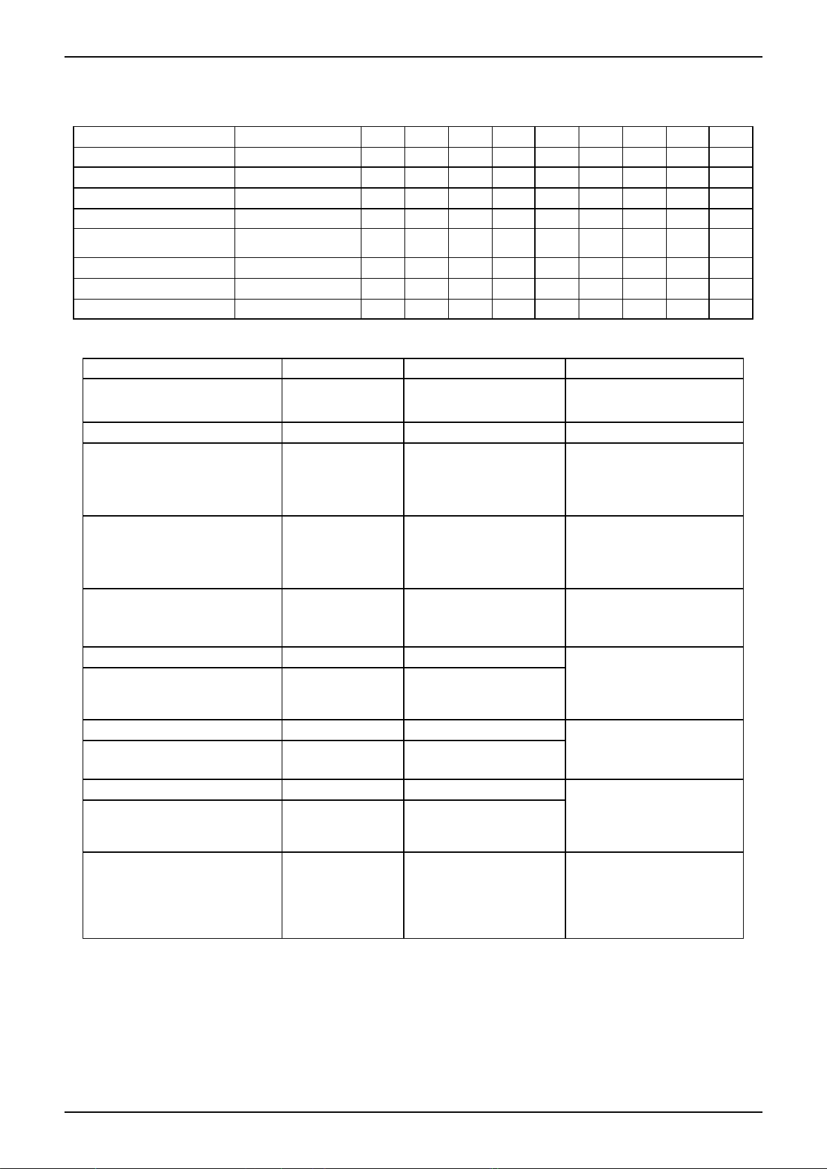
Super slim cassette
Duct
Ceiling-Floor
Compact Four-way cassette
Console
M Floor-standing
GA Floor-standing
2. External Appearance
2.1 Indoor Units
General Information 3
Page 6
External Appearance
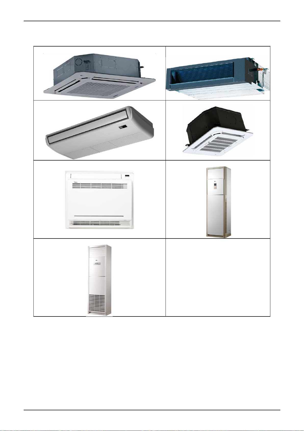
Single fan outdoor unit
Double fan outdoor unit
2.2 Outdoor Units
General Information 4
Page 7
Nomenclature
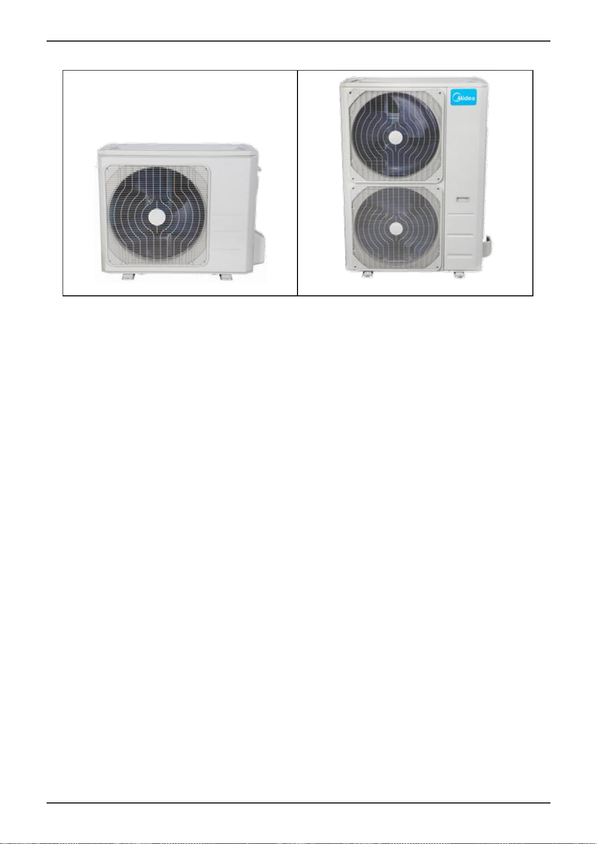
M U B T - 36 H R D N1- Q RC4
E n e rg y E ff ic ie n cy C o d e
P o w e r S u p ply
Q 2 20 ~ 24 0V ,1 N, 5 0H z
R 3 80 ~ 42 0 V , 3N , 5 0 H z
N 2 20 ~ 23 0 V , 1N , 6 0 H z
D 2 20 V ~ , 3N , 6 0 H z
C 38 0 ~4 2 0V ,3 N ,6 0 H z
R e fr i g era n t
N1 R 4 10 A -- R 2 2
D D C In v erte r - - O n -O ff
F F ull D C
C o n tr o l M o d e
W W ire d C o n tro l E E le ctr ic C on trol
M M ec h an ica l C o ntro l R R e m ote C on trol
F u n c tio n C o d e
C C o o ling O n ly H C oolin g & H ea ting
A C oo lin g & H e a ting + P TC
C ap a c ity (×1 0 00 B tu /h )
T T ro pica l C on ditio n
-- T 1 C on d itio n
D e s ig n ed T im e
A T im e A D es ig n ed B T im e B D e s ig n ed
C T im e C D e s ig n ed D T im e D D e s ig n ed
P ro d u ct C a te g o ry
C C a s sette T yp e V A H U T ype
T D u c t T y pe F C on s o le T ype
U C e ilin g & Floo r T y pe
H H ig h S t a tic P re ssu re D uc t T y p e
M ide a
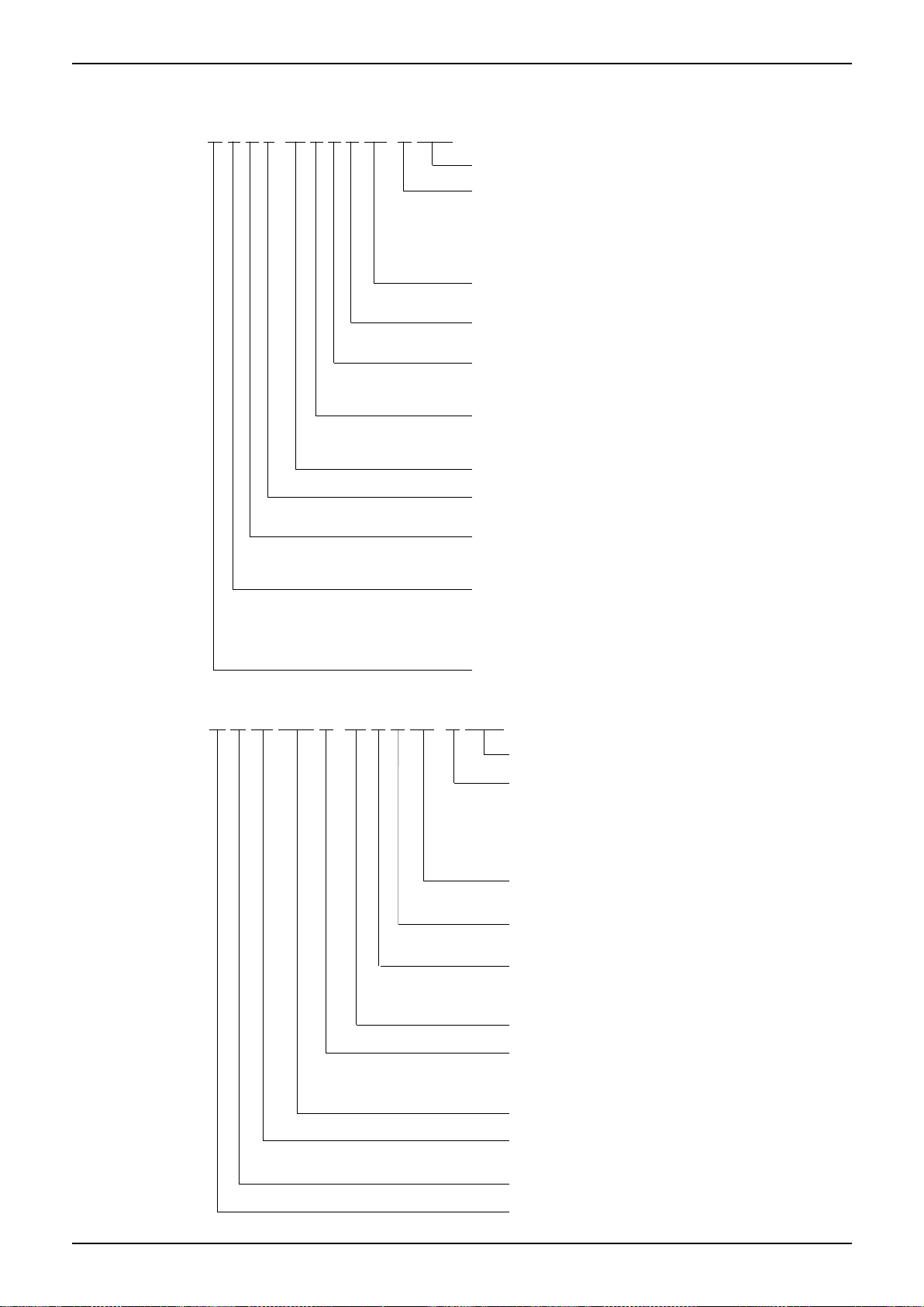
M O T4 D 3 0 U - 36 H D N1- R R C 4
E n erg y E f f ic ie nc y C o d e
P o w e r S u pp ly
Q 22 0~ 24 0 V ,1 N , 5 0 H Z
R 38 0~ 4 20 V, 3N , 5 0H z
N 22 0~ 2 30 V, 1N , 6 0H z
D 22 0V ~, 3 N , 6 0 H z
C 3 80 ~4 2 0v ,3 N,6 0 H Z
R efrige ra n t
N1 R 41 0 A -- R 2 2
D D C Inv erte r -- O n -O ff
F F ull D C
F un ctio n C o d e
C C o olin g O n ly H C o olin g & H e a tin g
A C o olin g & H ea ting +P TC
C a p a c it y (×1 0 0 0B tu/h )
U S id e D isc h arg e O utdo or U nit
V T op D is ch a rge O u td oo r U nit
S C e n tr ifug al F an O u td oo r U nit
O u td oo r S iz e C od e
T T rop ic a l C on d ition
-- T 1 C on ditio n
O O utd o or un it
M id e a
3. Nomenclature
3.1 Indoor Unit
3.2 Outdoor Unit
General Information 5
Page 8

Indoor Units
Part 2
Indoor Units
Super Slim Cassette Type ............................................... 7
A5 Duct Type ................................ ................................. 22
A6 Duct Type ................................ ................................. 38
Ceiling & Floor Type ...................................................... 52
Four-way Cassette Type (Compact) .............................. 66
Console Type ................................ ................................ 76
M Floor-standing Type .................................................. 88
GA Floor-standing Type ...............................................100
Indoor Units 6
Page 9

Super Slim Cassette Type
Super Slim Cassette Type
1. Features ...................................................................... 8
2. Dimensions ................................................................11
3. Service Space............................................................ 12
4. Wiring Diagrams ................................ ........................ 13
5. Air Velocity Distributions (Reference Data) ............... 14
6. Electric Characteristics ............................................. 17
7. Sound Levels............................................................. 18
8. Accessories ................................ ............................... 19
9. The Specification of Power........................................ 20
10. Field Wiring ............................................................. 21
Indoor Units 7
Page 10
Features
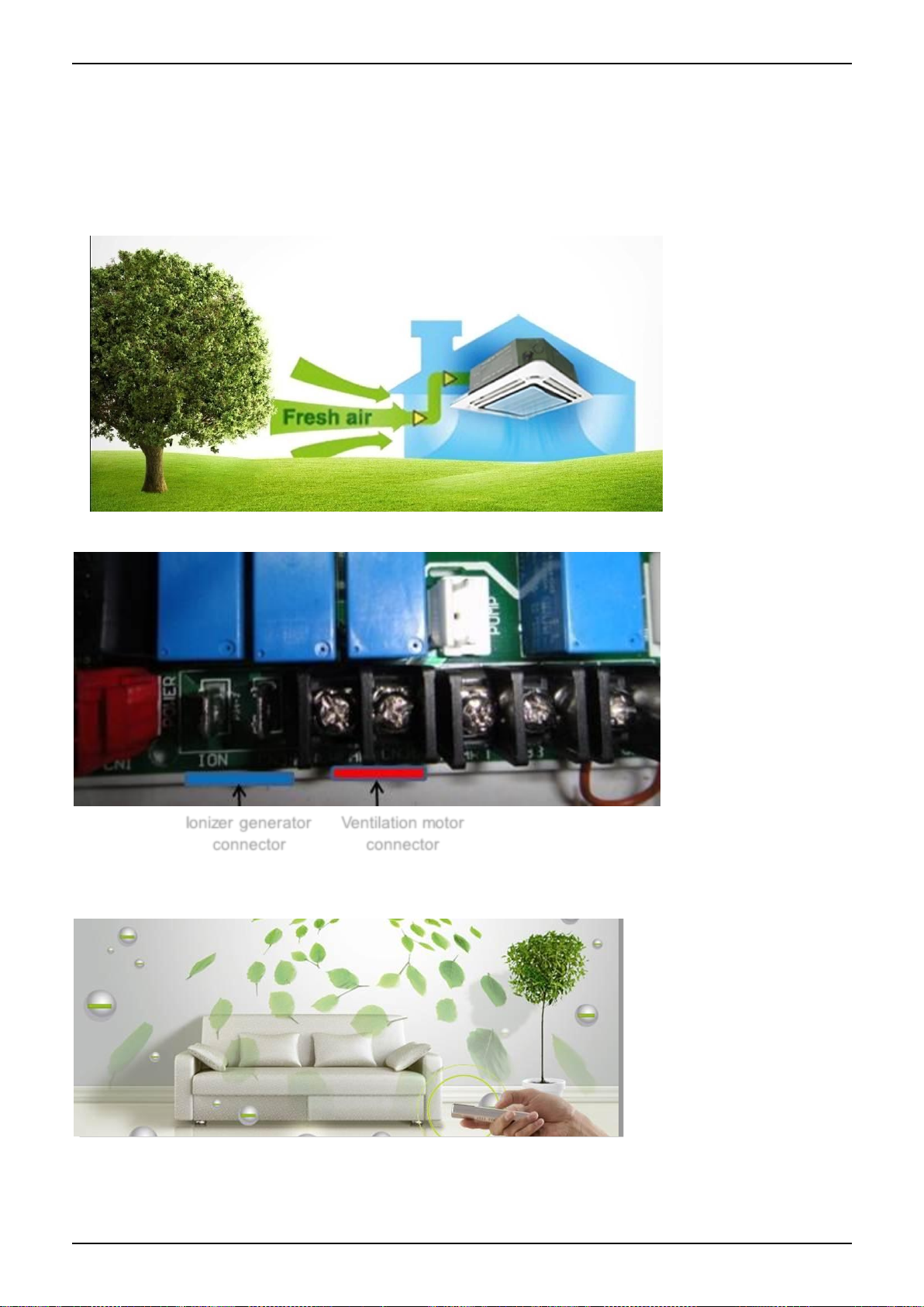
Ionizer generator
connector
Ventilation motor
connector
1. Features
1.1 Overview
Compact design, super slim body size, less space requiring in installation
Each louver can be separately controlled, more comfort air blowing is possible.
Auto-lifting panel design, more convenient to clean and maintain the filter. (optional)
1.2 Fresh air intake function
Fresh air fulfills air quality more healthy and comfortable.
Ventilation motor is optional to increase the effect of fresh air.
1.3 Optional ionizer generator
Ionizer generator is optional to get refreshing air to your room.
Ionizer can be switched on or off by remote controller.
When pressing the Clean Air button on the remote controller, Ionizer will work and the indicator light on
display board will shine.
1.4 External air duct design
Reserve external air duct, more flexible for the air supply.
Indoor Units 8
Page 11
Features
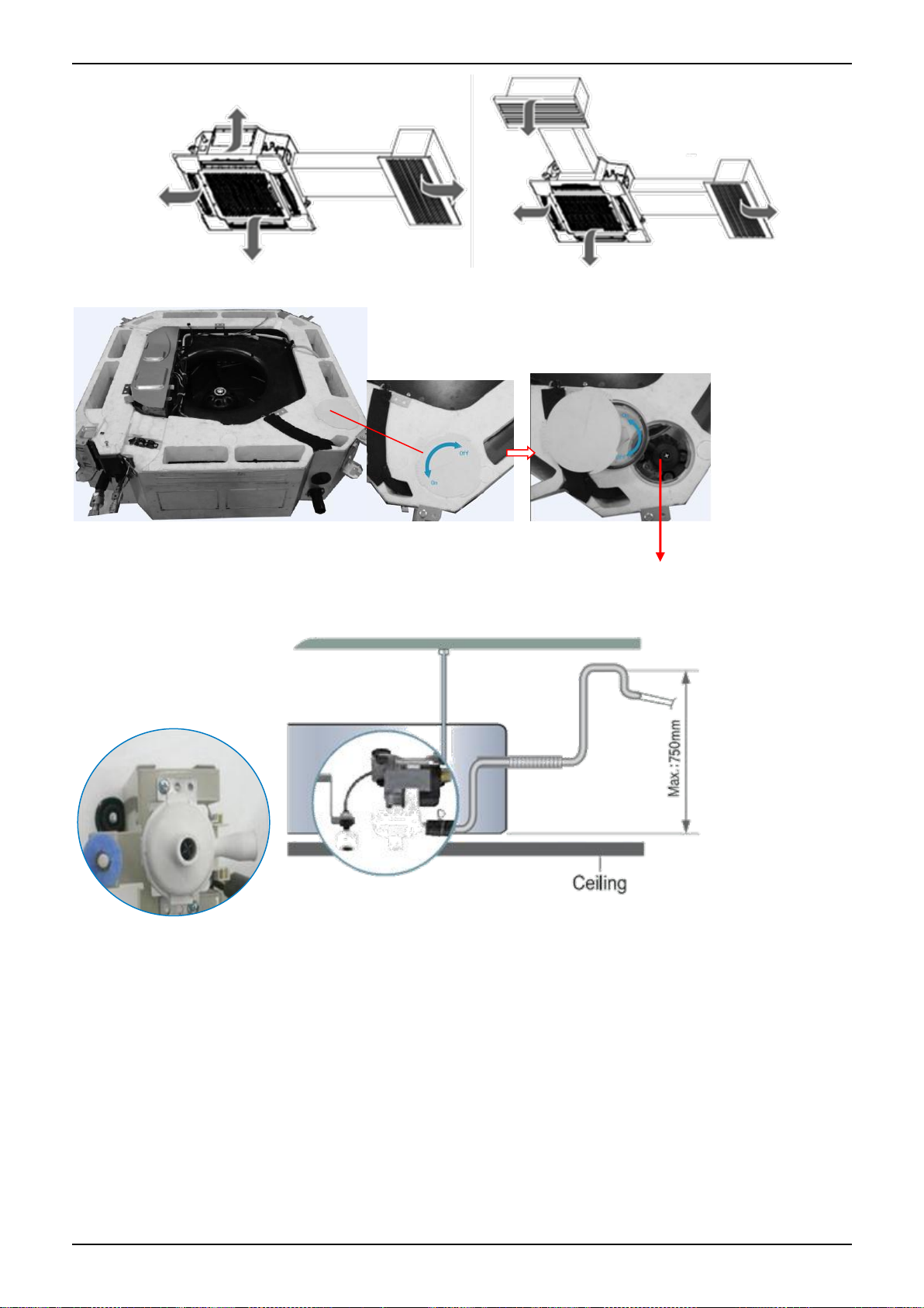
Draining Pump
1.5 Built-in draining pump
Due to the improvement of structure, more convenient to repair or replace the draining pump.
Built-in draining pump to make sure condensed water drain out reliably.
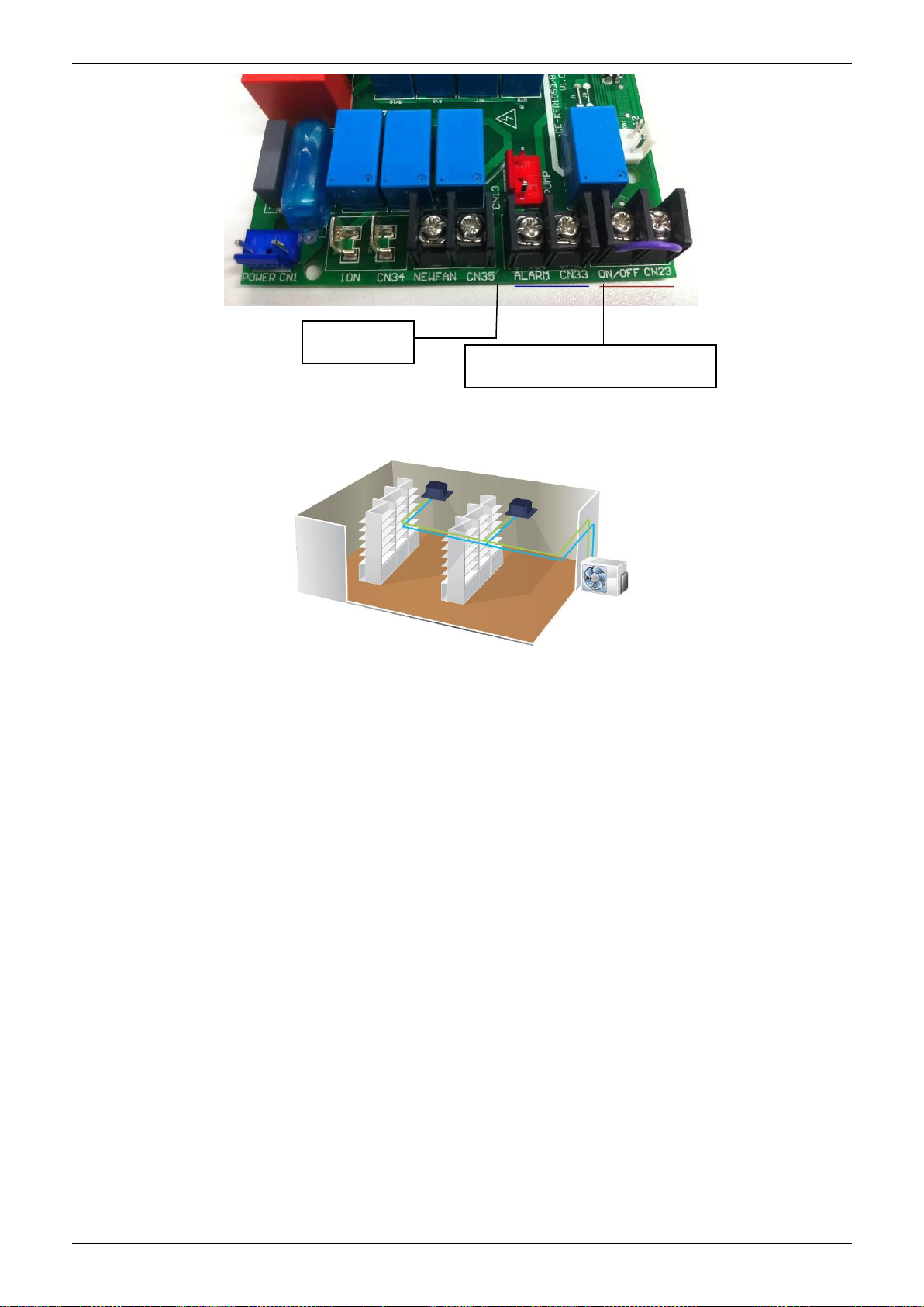
1.6 Terminals for alarm lamp and long-distance on-off controller connection are
standard
Reserve terminals for the connection of alarm lamp and long-distance on-off controller, more human
control.
Indoor Units 9
Page 12
Features
Alarm lamp
Long-distance on-off controller
1.7 Twins Combination(18k-30k)
The units can be installed as Twin systems: one outdoor unit can connect with two indoor units. The
indoor units can be combined in any of the different available ratings.
Indoor Units 10
Page 13
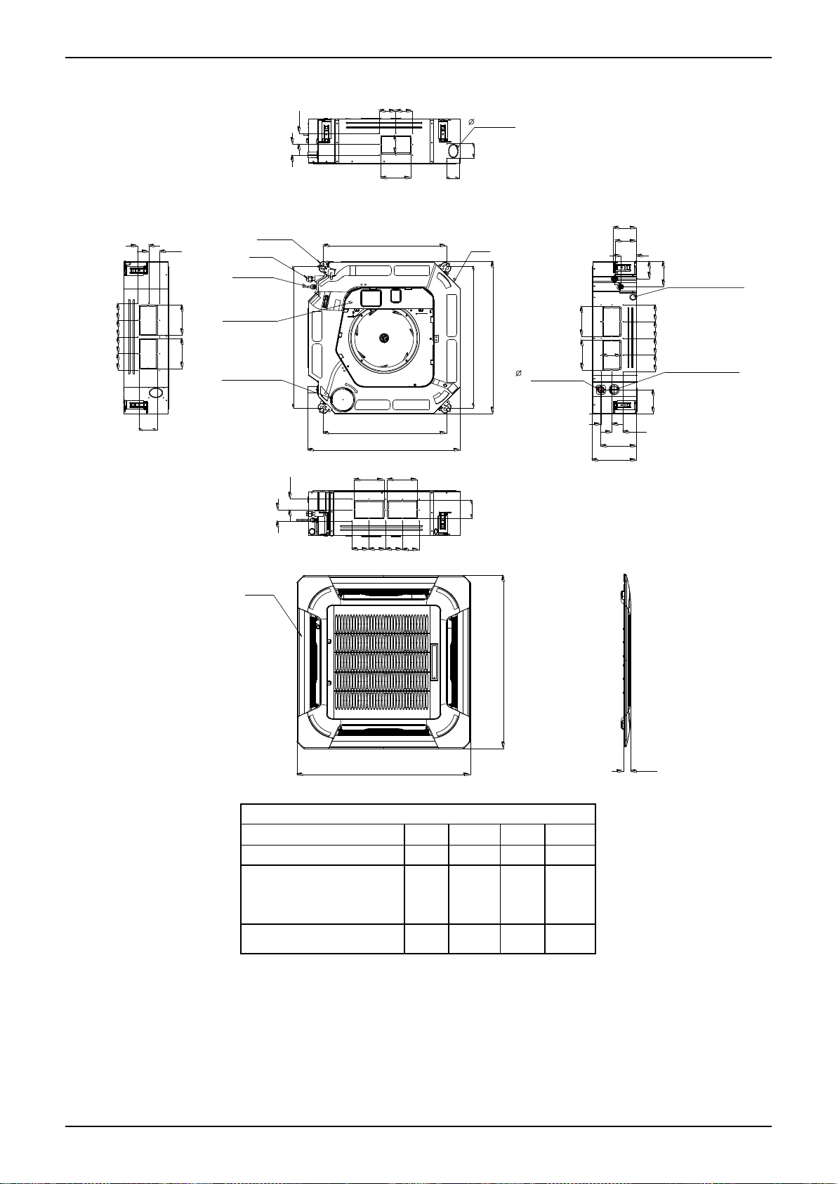
Dimensions
840
840
950
950
C
Te s t m ou th &
Te s t co v e r
D r a in h o le
32
W iring c o n ne c tio n p o rt
680
780
780
680
136
126
91
196
132
A
A
B
A
A
B
A
A
B
A
B
S e r v ic e h o le fo r
drainin g pum p
Fre s h a ir in take
75
55
80
80
4-in sta ll h a nger
G a s s id e
Liq uid s ide
E -p a rts box
135
90
P a n el
B o d y
92929292
D
D
92 92
D
D
D
D
92
9292
92
92 92
92
92
D
D
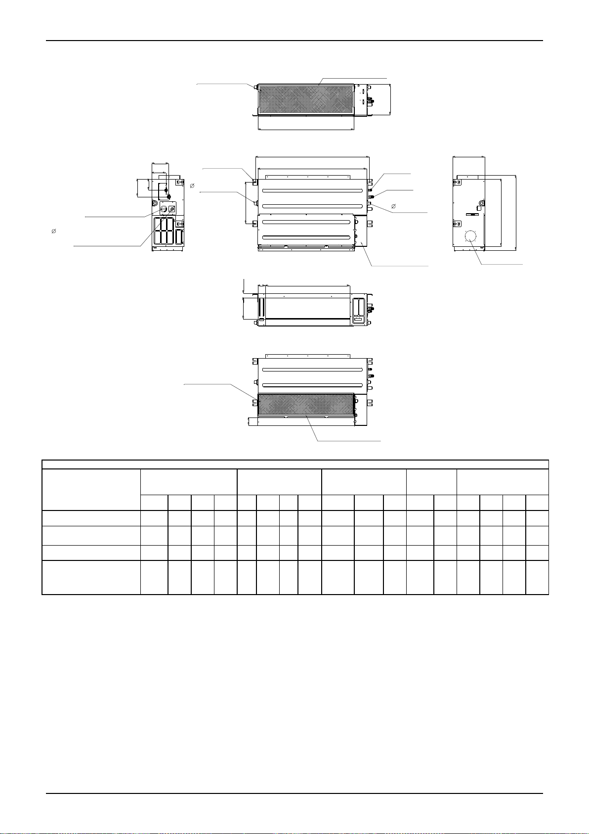
Unit: mm
Model
A B C D MCD-18HRFN1-QRD0
160
75
205
50
MCD-24HRFN1-QRD0
MCD-30HRFN1-QRD0
MCD-36HRFN1-QRD0
MCD-42HRFN1-QRD0
160
95
245
60
MCD-48HRFN1-QRD0
MCD-55HRFN1-QRDO
160
95
287
60
2. Dimensions
Indoor Units 11
Page 14
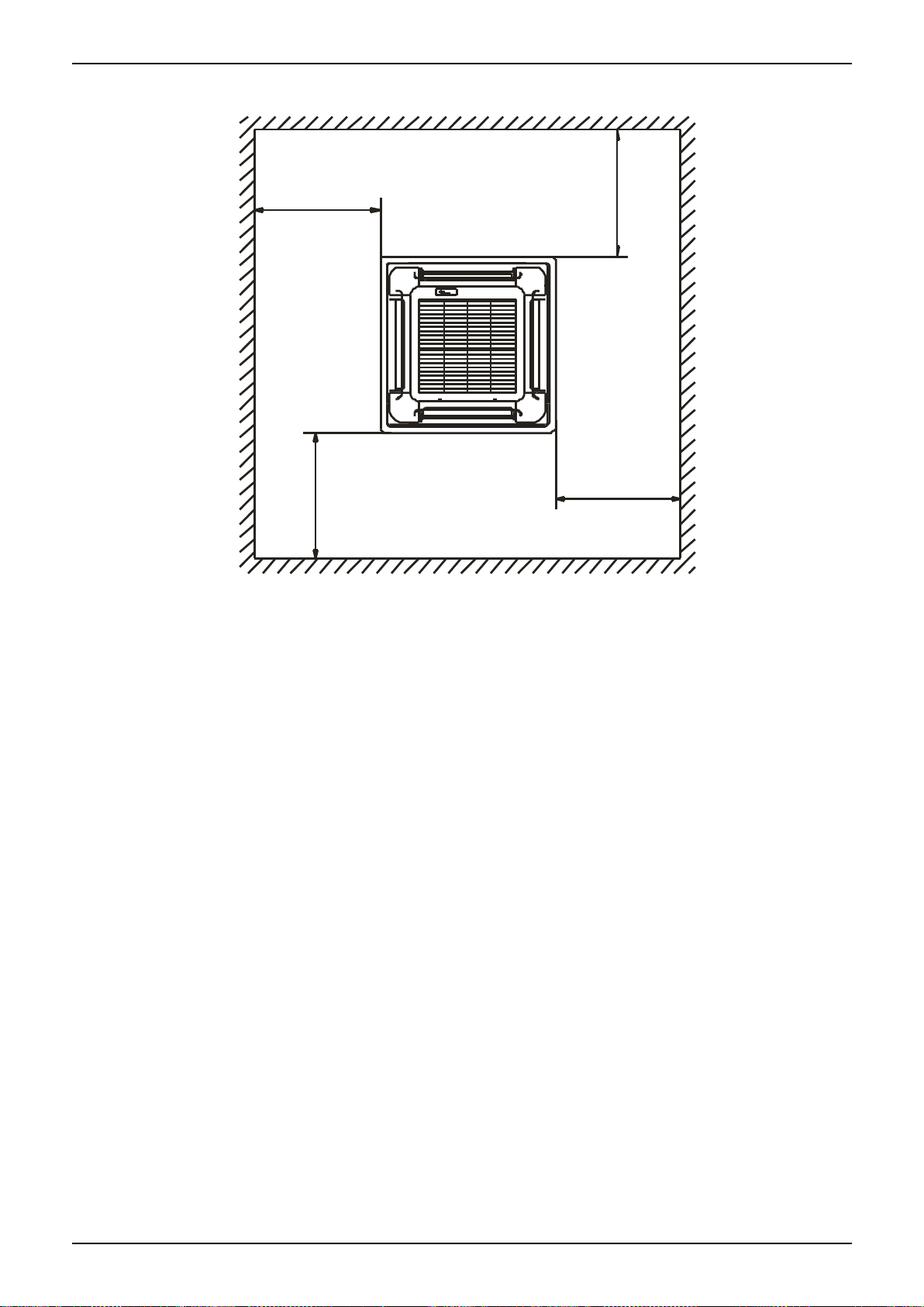
>1000m m
>1000mm
>1000mm
>1000mm
780(Hook-location)
880(Ceiling hole)
>2500mm
out let intle t outlet
ground
Chart 1
No te:
880mm
Hook
B
Panel
Chart 2
Body
Bolt M6X12
180 00-24000Btu/h(R 22) Series A 26 0mm
36000-48000Btu/h(R 22) Series A 330mm
≥
≥
No te:
180 00- 24000B tu/h(R 22) Seri es B= 240mm
3 60 00-48000Btu /h(R 22) Series B= 310mm
Service Space
3. Service Space
Indoor Units 12
Page 15
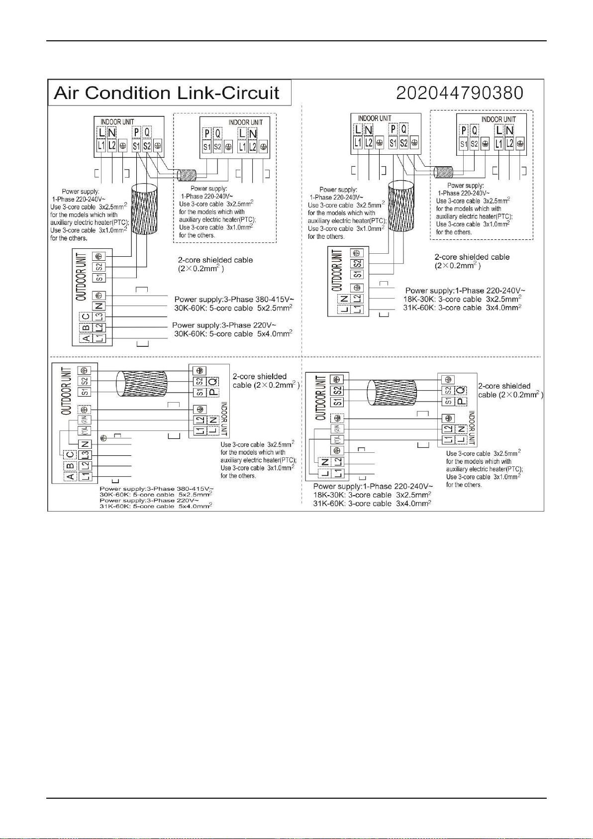
Wiring Diagrams
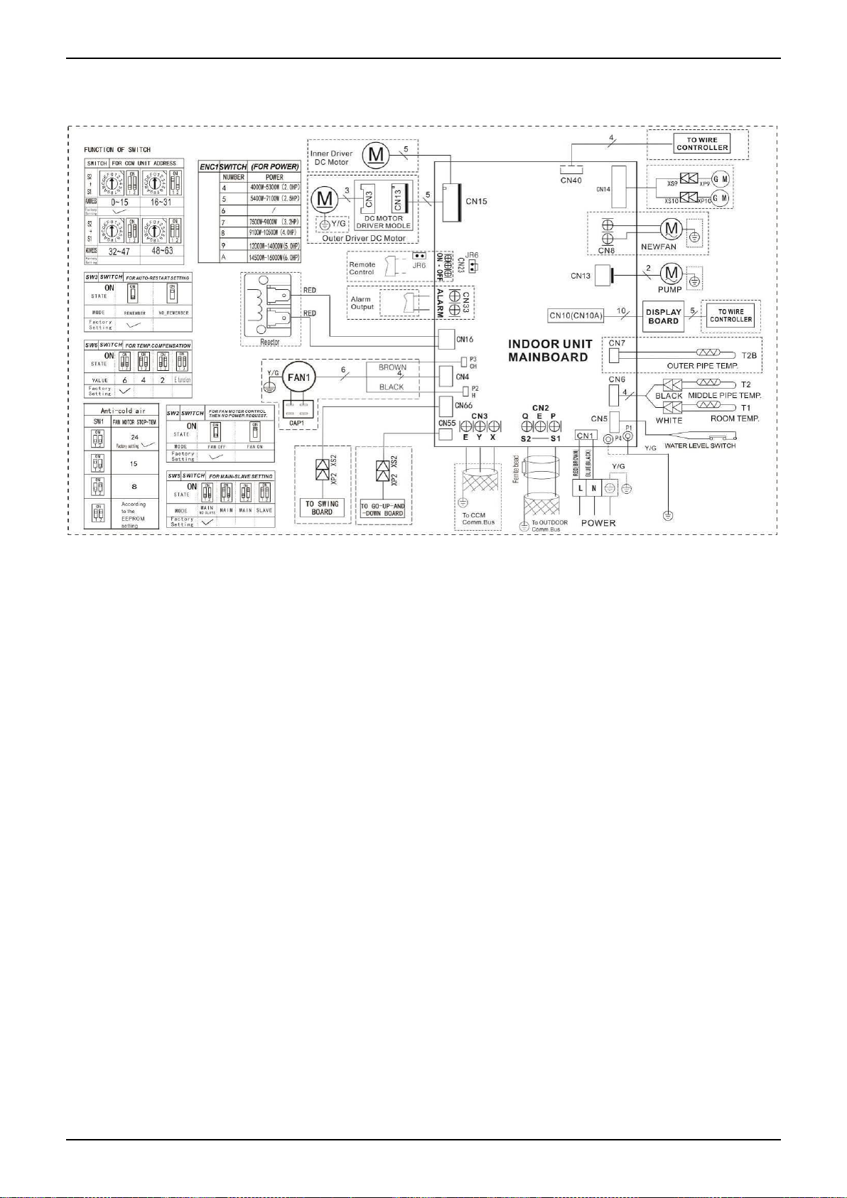
4. Wiring Diagrams
MCD-18HRFN1-QRD0 MCD-24HRFN1-QRD0 MCD-30HRFN1-QRD0 MCD-36HRFN1-QRD0
MCD-42HRFN1-QRD0 MCD-48HRFN1-QRD0 MCD-55HRFN1-QRDO
Indoor Units 13
Page 16
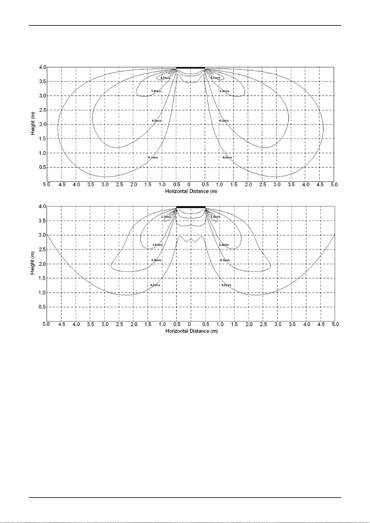
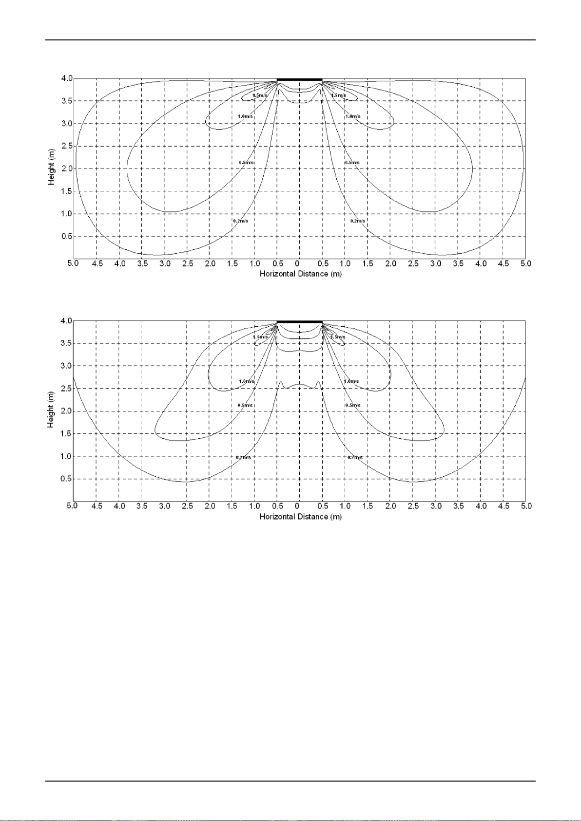
Air Velocity Distributions (Reference Data)
5. Air Velocity Distributions (Reference Data)
18-24K:
Cooling:
Heating:
Indoor Units 14
Page 17
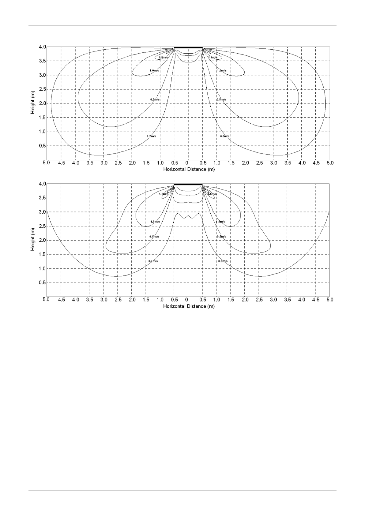
Air Velocity Distributions (Reference Data)
30-42K:
Cooling:
Heating:
Indoor Units 15
Page 18
Air Velocity Distributions (Reference Data)
48-55K:
Cooling:
Heating:
Indoor Units 16
Page 19

Electric Characteristics
Model
Indoor Unit
Power
Supply
Hz
Voltage
Min
Max
MFA
MCD-18HRFN1-QRD0
50
220-240V
198V
254V
/
MCD-24HRFN1-QRD0
50
220-240V
198V
254V
/
MCD-30HRFN1-QRD0
50
220-240
198
254
/
MCD-36HRFN1-QRD0
50
220-240V
198V
254V
/
MCD-42HRFN1-QRD0
50
220-240V
198V
254V / MCD-48HRFN1-QRD0
50
220-240V
198V
254V
/
MCD-55HRFN1-QRDO
50
220-240V
198V
254V
/
6. Electric Characteristics
Notes:
MFA: Max. Fuse Amps. (A)
Indoor Units 17
Page 20
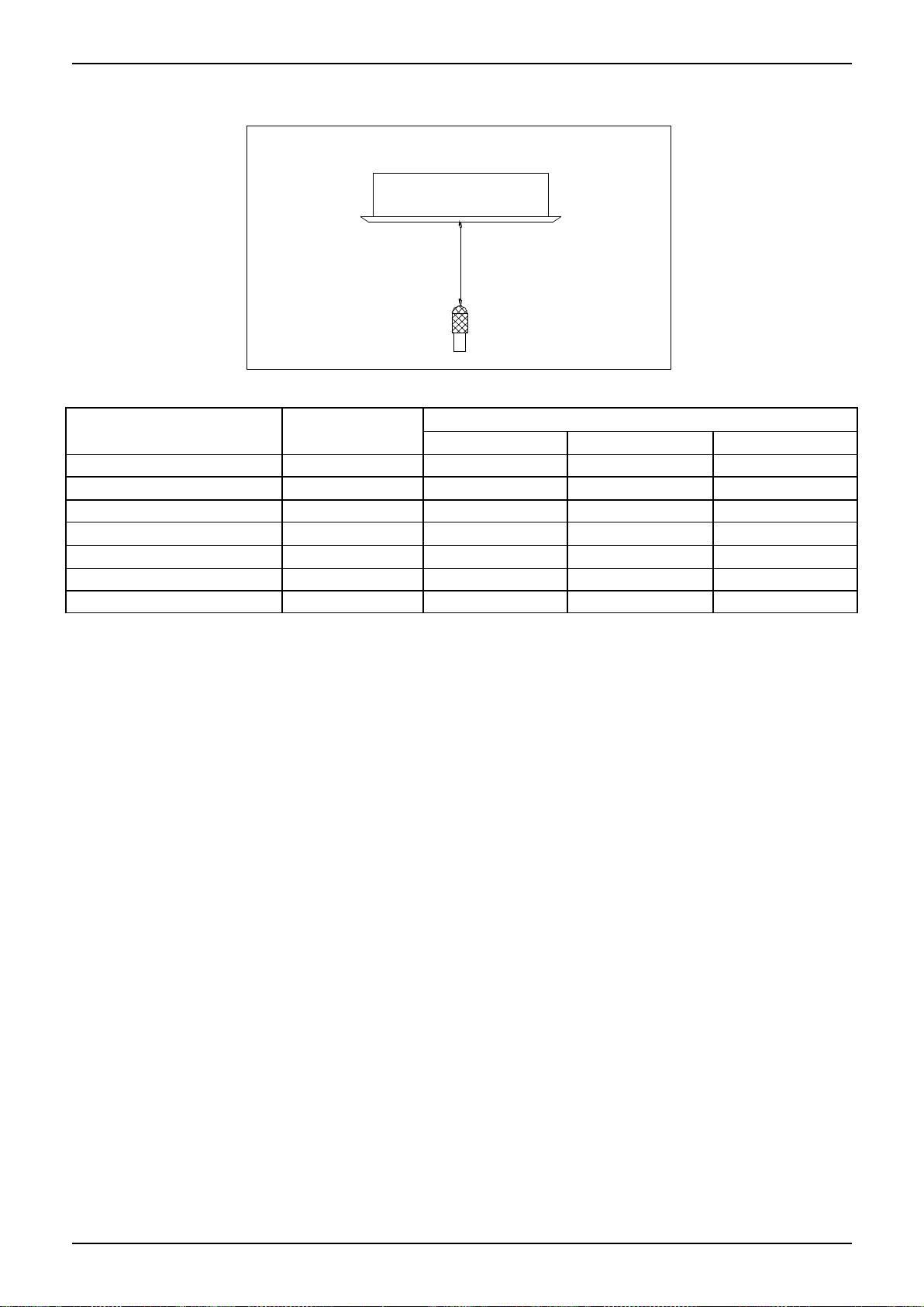
Sound Levels
1 . 4 m
M ic r o p h on e
Model
Noise Power dB(A)
Noise level dB(A)
H M L
MCD-18HRFN1-QRD0
56
46
41
37
MCD-24HRFN1-QRD0
62
46
42
39
MCD-30HRFN1-QRD0
65
53
48
44
MCD-36HRFN1-QRD0
65
56
52
48
MCD-42HRFN1-QRD0
64
52
40
47
MCD-48HRFN1-QRD0
65
55
51
48
MCD-55HRFN1-QRDO
69
52
49
46
7. Sound Levels
Indoor Units 18
Page 21
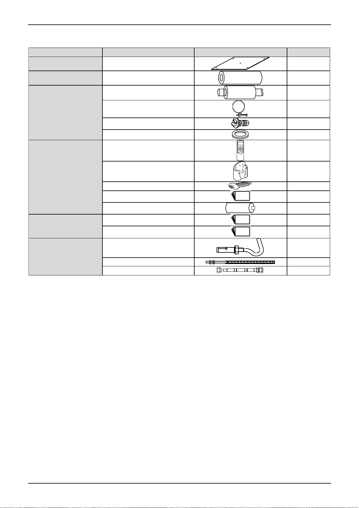
Accessories
Name
Shape
Quantity
Installation Fittings
Installation paper board
1
Tubing & Fittings
Soundproof / insulation sheath
1
Drainpipe Fittings
Out-let pipe sheath
1
Out-let pipe clasp
1
Drain joint
1
Seal ring
1
Remote controller & Its
Frame(The product you
have might not be
provided the following
accessories)
Remote controller & Its Frame
1
Remote controller holder
1
Mounting screw(ST2.9×10-C-H)
2
Remote controller manual
1
Alkaline dry batteries (AM4)
2
Others
Owner's manual
1
Installation manual
1
Installation accessory
(The product you have
might not be provided the
following accessories
Expansible hook
4
Installation hook
4
Orifice 1
8. Accessories
Indoor Units 19
Page 22
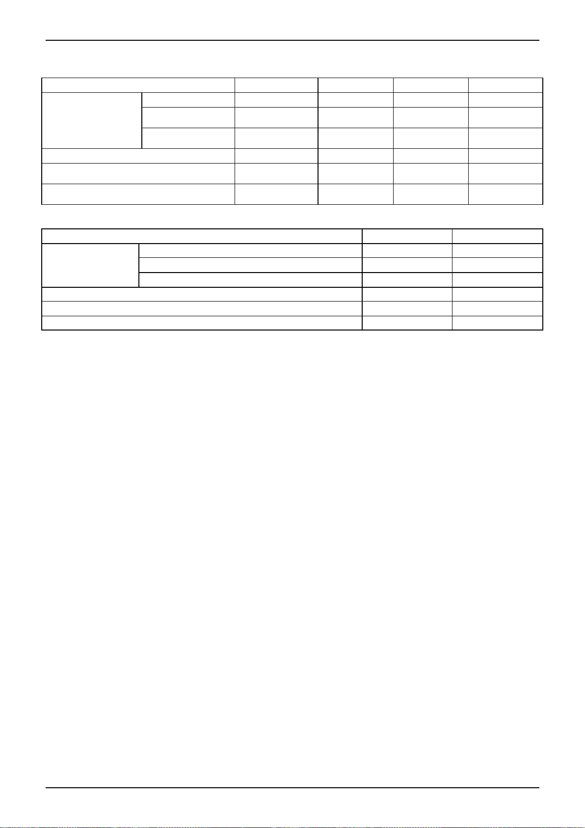
The Specification of Power
Model(Btu/h)
18000~24000
30000
36000
36000
POWER
Phase
1-phase
1-phase
1-phase
3-phase
Frequency and
Voltage
220-240V, 50Hz
220-240V, 50Hz
220-240V, 50Hz
380-415V, 50Hz
POWER WIRING
(mm2)
3×2.5
3×2.5
3×4.0
5×2.5
CIRCUIT BREAKER/Fuse (A)
30/20
40/30
40/30
30/20
Indoor/Outdoor Connecting Wiring
(Weak Electric Signal) (mm2)
2×0.2
2×0.2
2×0.2
2×0.2
Indoor/Outdoor Connecting Wiring
(Strong Electric Signal) (mm2)
3×1.0
3×1.0
3×1.0
3×1.0
Model(Btu/h)
42000~48000
42000~60000
POWER
Phase
1-phase
3-phase
Frequency and Voltage
220-240V, 50Hz
380-415V, 50Hz
Power Wiring (mm2)
3×4.0
5×2.5
Circuit Breaker/Fuse(A)
40/35
30/25
Indoor/Outdoor Connecting Wiring(Weak Electric Signal) (mm2)
2×0.2
2×0.2
Indoor/Outdoor Connecting Wiring(Strong Electric Signal) (mm2)
3×1.0
3×1.0
9. The Specification of Power
Indoor Units 20
Page 23
Field Wiring
10. Field Wiring
Indoor Units 21
Page 24

A5 Duct Type
A5 Duct Type
1. Features .................................................................... 23
2. Dimensions ............................................................... 26
3. Service Space............................................................ 27
4. Wiring Diagrams ................................ ........................ 28
5. Static Pressure .......................................................... 30
6. Electric Characteristics ............................................. 33
7. Sound Levels............................................................. 34
8. Accessories ................................ ............................... 35
9. The Specification of Power........................................ 36
10. Field Wiring ............................................................. 37
Indoor Units 22
Page 25
Features
Filter
Panel
Air intake from rear (Standard)
Air intake from bottom (Optional)
Front Board
1. Features
1.1 Installation accessories: (Optional)
Front Board, Filter, Panel, for easy installation
1.2 Easy Installation: Two air inlet styles (Bottom side or Rear side)
Air inlet from rear is standard for all capacity; air inlet from bottom is optional.
The size of air inlet frame from rear and bottom is same, it’s very easy to move the cover from bottom to
rear side, or from rear to the bottom, in order to matching the installation condition.
1.3 Fresh air intake function(Optional for 18~60k)
Install one duct from the reserved fresh-air intake to outdoor.
Continually inhale the fresh air to improve the quality of the indoor air, fulfills air quality more healthy and
comfortable.
1.4 Easy maintenance
Clean the filter (Optional, standard product without filter)
It is easy to draw out the filter from the indoor unit for cleaning, even the filter is installed in rear side or
bottom side.
Indoor Units 23
Page 26
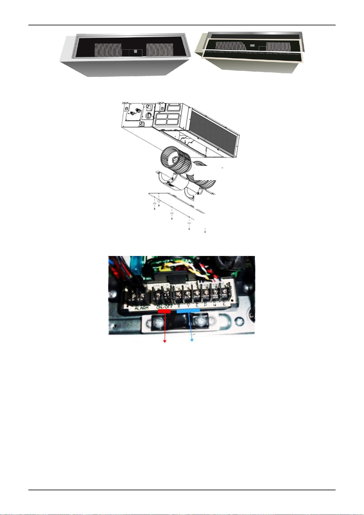
Features
Motor
Blower Housing
Ventilated Panel
Remote on-off ports
Central control ports
Replace the motor or centrifugal fan
Remove the ventilated panel firstly. Remove a half of blower housing and take out the motor with
centrifugal fan. Directly remove two bolts, and then replace the motor or centrifugal fan easily.
1.5 Reserved remote on-off and central control ports
Reserved remote on-off ports and central control ports, can connect the cable of an on-off controller or a
central controller to realize remote on-off control function or group control function.
1.6 Built-in drain pump (Optional):
Built-in drain pump can lift the water to 750mm upmost. It’s convenient to install drainage piping under
most space condition.
Indoor Units 24
Page 27
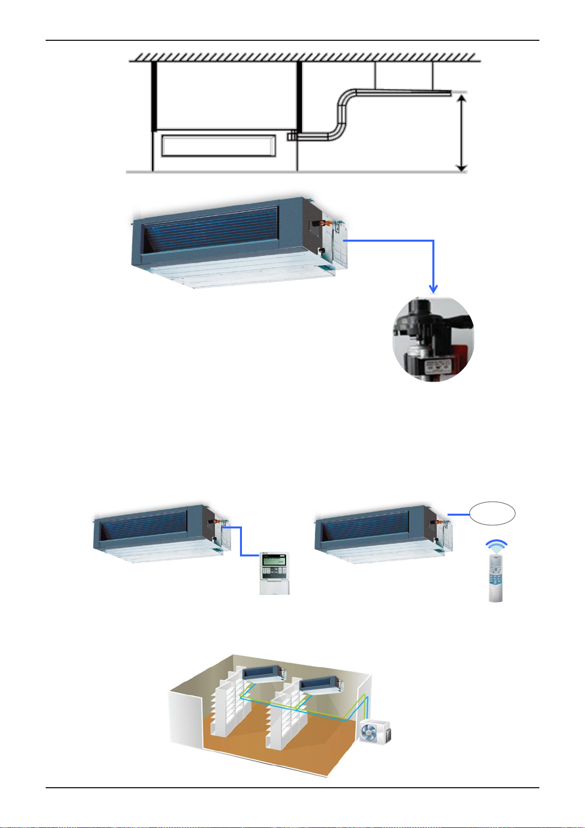
Features
Displa
750mm upmost
Wired Controller (Standard)
Remote Controller (Optional)
1.7 Built-in display board
The standard indoor unit can be controlled by wired controller.
There is a display board with a receiver in the E-box. Move out the display, and fix it in other place, even
in the distance of 2m. The unit will realized remoter control.
The wired controller and the display board can display the error code or protection code when the chips
detect some failure.
1.8 Twins Combination
The units can be installed as Twin systems: one outdoor unit can connect with two indoor units. The
indoor units can be combined in any of the different available ratings.
Indoor Units 25
Page 28
Dimensions
A
C
B
D
J
I
K
A ir filte r ( op tion a l )
air in le t fro m re ar s id e
air in le t fro m b otto m s id e
FE
G
H
E le c tric co ntr o l b o x
A ir filte r ( op tion a l )
L
4-in stall h an g er
G as side
Liqu id s id e
M
W1
W2
H1
H2
25 D rain co nn e ctin g pipe
( for p u m p )
Te st m o uth & T es t co v er
Fre s h air in ta k e
25 D rain p ip e
25 D rain p ip e
Note: standard product without filter Unit: mm
Model
Outline dimension(mm)
Air outlet opening size
Air return opening size
Size of
install
hanger
Size of refrigerant pipe
A B C D E F G H I J K L M
H1
H2
W1
W2
MTBU-12HWFN1-QRD0W
700
210
635
570
65
493
35
119
595
200
80
740
350
120
143
95
150
MTB-18HWFN1-QRD0
MTB-24HWFN1-QRD0
920
270
635
570
65
713
35
179
815
260
20
960
350
120
143
95
150
MTB-30HWFN1-QRD0
1140
270
775
710
65
933
35
179
1035
260
20
1180
490
120
143
95
150
MTB-36HWFN1-QRD0
MTB-42HWFN1-QRD0
MTB-48HWFN1-QRD0
MTB-55HWFN1-QRD0
1200
300
865
800
80
968
40
204
1094
288
45
1240
500
175
198
155
210
2. Dimensions
Indoor Units 26
Page 29
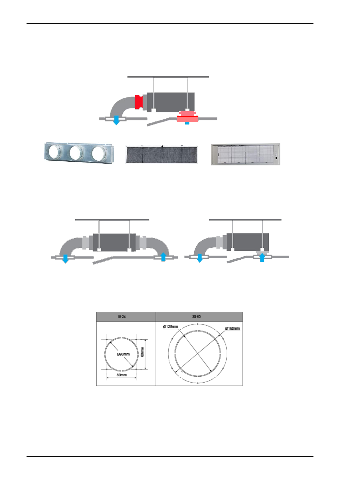
Service Space
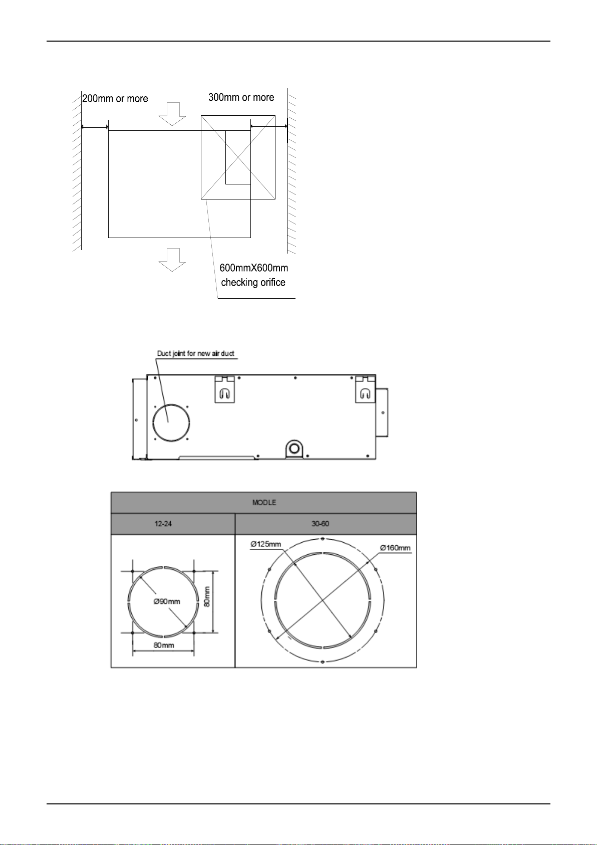
3. Service Space
Ensure enough space required for installation and maintenance.
All the indoor units reserve the hole to joint the fresh air pipe. The hole size as following:
Indoor Units 27
Page 30
Wiring Diagrams
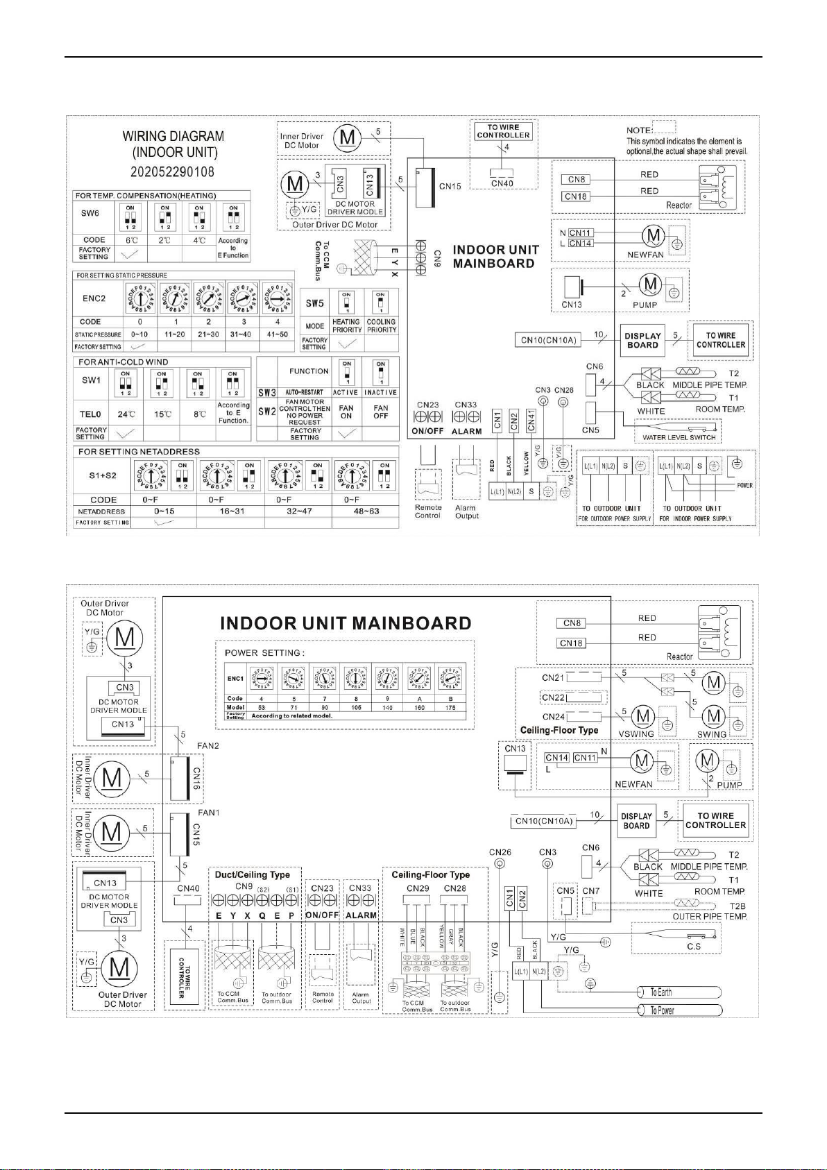
4. Wiring Diagrams
MTBU-12HWFN1-QRD0W
MTB-18HWFN1-QRD0
Indoor Units 28
Page 31

Wiring Diagrams
MTB-24HWFN1-QRD0, MTB-30HWFN1-QRD0, MTB-36HWFN1-QRD0, MTB-42HWFN1-QRD0
MTB-48HWFN1-QRD0, MTB-55HWFN1-QRD0
Pre-setting Instructions
Indoor Units 29
Page 32

Static Pressure
5. Static Pressure
MTBU-12HWFN1-QRD0W
MTB-18HWFN1-QRD0
Indoor Units 30
Page 33

Static Pressure
MTB-24HWFN1-QRD0
MTB-30HWFN1-QRD0
Indoor Units 31
Page 34

Static Pressure
MTB-36HWFN1-QRD0
MTB-42HWFN1-QRD0, MTB-48HWFN1-QRD0, MTB-55HWFN1-QRD0
Indoor Units 32
Page 35

Electric Characteristics
Model
Indoor Unit
Power Supply
Hz
Voltage
Min.
Max.
MFA
MTBU-12HWFN1-QRD0W
50
220-240V
198V
254V
/
MTB-18HWFN1-QRD0
50
220-240V
198V
254V
/
MTB-24HWFN1-QRD0
50
220-240V
198V
254V
/
MTB-30HWFN1-QRD0
50
220-240V
198V
254V
/
MTB-36HWFN1-QRD0
50
220-240V
198V
254V
/
MTB-42HWFN1-QRD0
50
220-240V
198V
254V
/
MTB-48HWFN1-QRD0
50
220-240V
198V
254V
/
MTB-55HWFN1-QRD0
50
220-240V
198V
254V
/
6. Electric Characteristics
Note:
MFA: Max. Fuse Amps. (A)
Indoor Units 33
Page 36
Sound Levels
S u c tio n
D is ch a rge
M ic rop h o n e
1.4m
C o n c ea le d D uc t T yp e
D u c tD u c t
Model
Sound Power
dB(A)
Noise level dB(A)
H M L
MTBU-12HWFN1-QRD0W
59
42
38
35
MTB-18HWFN1-QRD0
57
44
40
37
MTB-24HWFN1-QRD0
60
44
42
38
MTB-30HWFN1-QRD0
65
53
48
44
MTB-36HWFN1-QRD0
64
46
43
40
MTB-42HWFN1-QRD0
68
49
47
44
MTB-48HWFN1-QRD0
68
50
47
44
MTB-55HWFN1-QRD0
69
50
47
45
7. Sound Levels
Indoor Units 34
Page 37

Accessories
Name
Shape
Quantity
Tubing & Fittings
Soundproof / insulation sheath
2
Binding tape
1
Seal sponge
1
Drainpipe Fittings
(for cooling & heating)
Drain joint
1
Seal ring 1
Wired controller & Its Frame
Wired controller
1
Others
Owner,s manual
1
Installation manual
1
EMS & It’s fitting
Magnetic ring (twist the electric wires L
and N around it to five circles)
1
8. Accessories
Indoor Units 35
Page 38

The Specification of Power
Model(Btu/h)
12000
18000-24000
30000
36000
36000
POWER
Phase
1-phase
1-phase
1-phase
1-phase
3-phase
Frequency and
Voltage
220-240V,
50Hz
220-240V,
50Hz
220-240V,
50Hz
220-240V,
50Hz
380-415V,
50Hz
POWER
WIRING (mm2)
3×2.5
3×2.5
3×2.5
3×4.0
5×2.5
CIRCUIT BREAKER/Fuse (A)
20/16
30/20
40/30
40/30
30/20
Indoor/Outdoor Connecting
Wiring(Weak Electric Signal)
(mm2)
2×0.2
2×0.2
2×0.2
2×0.2
Indoor/Outdoor Connecting
Wiring(Strong Electric Signal)
(mm2)
4×1.0
3×1.0
3×1.0
3×1.0
3×1.0
Model(Btu/h)
42000~48000
42000-60000
POWER
Phase
1-phase
3-phase
Frequency and Voltage
220-240V, 50Hz
380-415V, 50Hz
Power Wiring (mm2)
3×4.0
5×2.5
Circuit Breaker/Fuse(A)
40/35
30/25
Indoor/Outdoor Connecting Wiring(Weak Electric Signal) (mm2)
2×0.2
2×0.2
Indoor/Outdoor Connecting Wiring(Strong Electric Signal) (mm2)
3×1.0
3×1.0
9. The Specification of Power
Indoor Units 36
Page 39

Field Wiring
10. Field Wiring
MTBU-12HWFN1-QRD0W
MTB-18HWFN1-QRD0, MTB-24HWFN1-QRD0, MTB-30HWDN1-QRD0, MTB-36HWFN1-QRD0
MTB-42HWFN1-QRD0, MTB-48HWFN1-QRD0, MTB-55HWFN1-QRD0
Indoor Units 37
Page 40

A6 Duct Type
A6 Duct Type
1. Features ................................................................ .... 39
2. Dimensions ............................................................... 44
3. Service Space................................ ............................ 45
4. Wiring Diagrams ................................ ........................ 46
5. Electric Characteristics ............................................. 47
6. Sound Levels............................................................. 48
7. Accessories ................................ ............................... 49
8. The Specification of Power........................................ 50
9. Field Wiring ............................................................... 51
Indoor Units 38
Page 41

Features
1. Features
1.1 Higher Static Pressure
As a ducted air conditioner with medium static pressure, it has the widest static pressure range.
The maximum static pressure reaches 160 Pa
1.2 Slim Design
The industry Lowest height is designed to be fitted into tight roof spaces.
*18K unit - 210mm,24K/36K unit - 249mm,48K unit -300mm
1.3 Constant air volume control
For ordinary duct, when the static pressure exceeds the expected range, it is fairly difficult even for an
experienced installer to calculate and adjust the air volume precisely.
With constant air volume control technology, the duct will automatically adjusts to perfect static pressure
and keep constant air volume.
1.4 Installation accessories: (Optional)
Front Board, Filter, Panel, for easy installation
Indoor Units 39
Page 42

Features
Air intake from rear (Standard)
Air intake from bottom (Optional)
Filter
Panel
Front Board
1.5 Flexible Air Intake Way (Bottom side or Rear side)
The frame size of air inlet in rear and bottom is the same. It’s very easy to switch to match different
application.
1.6 Communication wire connection
A6 duct uses two wires without polarity connection way, which almost has no mistake during the
installation.
1.7 Easy Clean
Clean the filter (Optional, standard product without filter)
It is easy to draw out the filter from the indoor unit for cleaning, even the filter is installed in rear side or
bottom side.
Indoor Units 40
Page 43

Features
With a larger window design, once the motor and the blower wheels have been detached, heat
exchanger and water receiver tray in behind can be seen very clearly. Dust can be easily removed from
the inside by vacuum
1.8 Easy maintenance
A6 duct allows operators maintenance the motor from the bottom more easily compare with that on the
top.
A6 duct has big space for maintenance at the side
Indoor Units 41
Page 44

Features
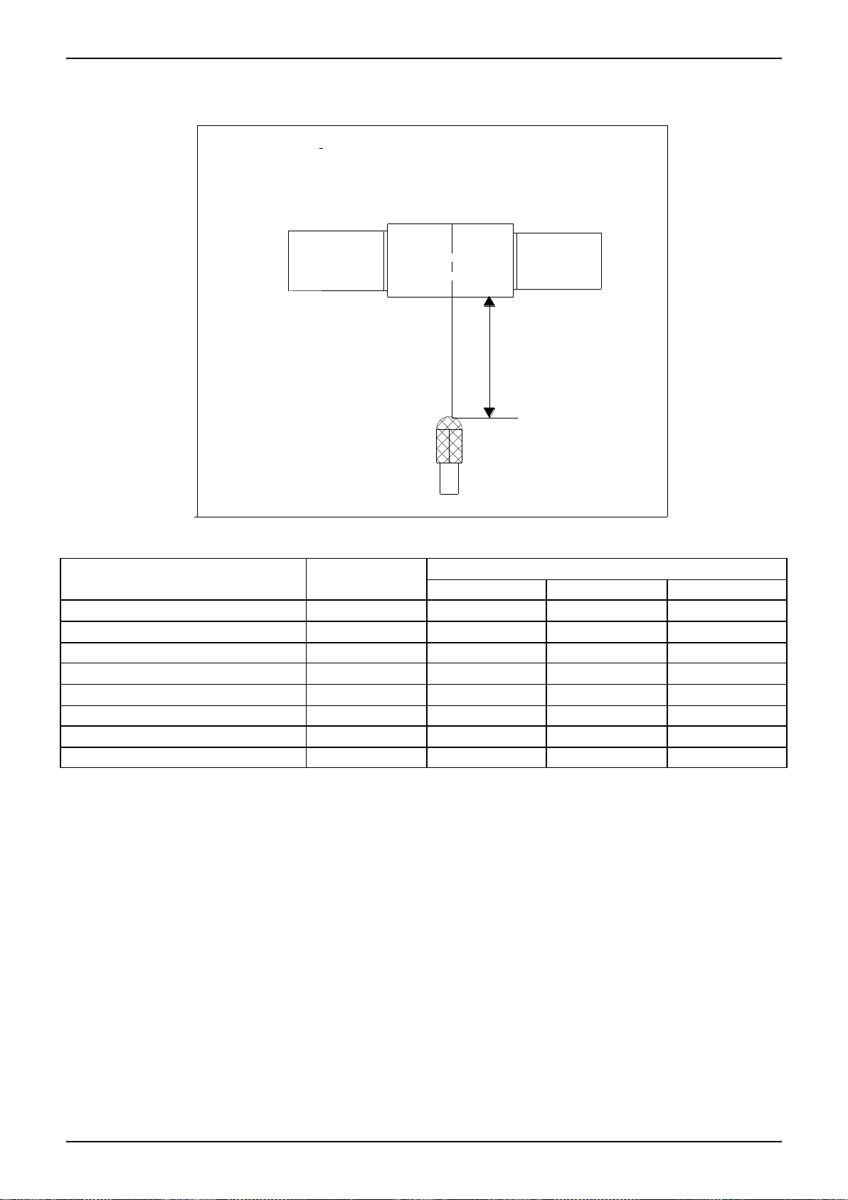
Max 750mm
1.9 Twins Function
The twin system connects two indoor units of the same type and capacity to one outdoor unit in order to
ensure more air distribution in a large zone. The controller can only control the master unit. The slave
unit will work in the same state as the master unit.
1.10 Fresh air intake function(Optional)
Install one duct from the reserved fresh-air intake to outdoor.
Continually inhale the fresh air to improve the quality of the indoor air, fulfills air quality more healthy and
comfortable.
A ventilation motor (provided by the installer) can be installed inside the fresh air duct to improve the
fresh air volume. There are reserved ports for this motor on main PCB (Standard for 3D inverter units,
and only optional for DC inverter 53~160 units).
1.11 Built-in drain pump (Optional)
Built-in drain pump can lift the water to 750mm upmost, which widens the drainage piping range.
Indoor Units 42
Page 45

Features
Indoor Units 43
Page 46

Dimensions
Model
(KBtu/h)
unit A B C D E F G H I J K L M H1
H2
W1
W2
18
mm
880
210
674
600
140
706
50
136
782
190
40
920
508
78
148
88
112
inch
34.65
8.27
26.54
23.62
5.51
27.80
1.97
5.35
30.79
7.48
1.57
36.22
20.00
3.07
5.83
3.46
4.41
24
mm
1100
249
774
700
140
926
50
175
1001
228 5 1140
598
80
150
130
155
inch
43.31
9.80
30.47
27.56
5.51
36.46
1.97
6.89
39.41
8.98
0.20
44.88
23.54
3.15
5.91
5.12
6.10
30/36
mm
1360
249
774
700
140
1186
50
175
1261
228 5 1400
598
80
150
130
155
inch
53.54
9.80
30.47
27.56
5.51
46.69
1.97
6.89
49.65
8.98
0.20
55.12
23.54
3.15
5.91
5.12
6.10
42/48/55
mm
1200
300
874
800
123
1044
50
227
1101
280 5 1240
697
80
150
185
210
inch
47.24
11.81
34.41
31.5
4.84
41.1
1.97
8.94
43.35
11.02
0.20
48.82
27.44
3.15
5.91
7.28
8.27
2. Dimensions
Indoor Units 44
Page 47

Service Space
3. Service Space
Ensure enough space required for installation and maintenance.
Indoor Units 45
Page 48

Wiring Diagrams
4. Wiring Diagrams
MTI-18HWFN1-QRD0, MTI-24HWFN1-QRD0, MTI-30HWFN1-QRD0, MTI-36HWFN1-QRD0,
MTI-42HWFN1-QRD0, MTI-48HWFN1-QRD0, MTI-55HWFN1-QRD0
Indoor Units 46
Page 49

Electric Characteristics
Model
Indoor Unit
Power Supply
Hz
Voltage
Min.
Max.
MFA
MTI-18HWFN1-QRD0
50
220-240
198
254
/
MTI-24HWFN1-QRD0
50
220-240
198
254
/
MTI-30HWFN1-QRD0
50
220-240
198
254
/
MTI-36HWFN1-QRD0
50
220-240
198
254
/
MTI-42HWFN1-QRD0
50
220-240
198
254
/
MTI-48HWFN1-QRD0
50
220-240
198
254
/
MTI-55HWFN1-QRD0
50
220-240
198
254
/
5. Electric Characteristics
Note:
MFA: Max. Fuse Amps. (A)
Indoor Units 47
Page 50

Sound Levels
S u c tio n
D is c h a rg e
M icro p h o n e
1.4m
C o n c ea le d D u c t T y pe
D u c tD u c t
Model
Sound Power
dB(A)
Noise level dB(A)
H M L
MTI-18HWFN1-QRD0
58
42
40
38
MTI-24HWFN1-QRD0
62
42
39
36
MTI-30HWFN1-QRD0
63
41
40
37
MTI-36HWFN1-QRD0
62
42
40
39
MTI-42HWFN1-QRD0
67
49
48
46
MTI-48HWFN1-QRD0
71
52
50
48
MTI-55HWFN1-QRD0
75
57
56
54
6. Sound Levels
Indoor Units 48
Page 51

Accessories
Tubing & Fittings
Name
Shape
Quantity
Soundproof / insulation sheath
2
Drainpipe Fittings
(for cooling & heating)
Drain joint
1
Seal ring 1
EMC & It’s Fitting
(for some models)
Magnetic ring
(twist the electric wires L and N around
the magnetic ring to five circles)
1
Wired controller & Its Frame
Wired controller
1
Owner,s manual of wired controller
1
Wired controller installation manual
1
Others
Owner,s manual
1
Installation manual
1
Connecting wire for display (2m)
1(on some
models)
Cord protection rubber ring
1(on some
models)
7. Accessories
Indoor Units 49
Page 52

The Specification of Power
Model(Btu/h)
18000-24000
30000
36000
36000
POWER
Phase
1-phase
1-phase
1-phase
3-phase
Frequency and
Voltage
220-240V, 50Hz
220-240V, 50Hz
220-240V, 50Hz
380-415V, 50Hz
POWER
WIRING (mm2)
3×2.5
3×2.5
3×4.0
5×2.5
CIRCUIT BREAKER/Fuse (A)
30/20
40/30
40/30
30/20
Indoor/Outdoor Connecting Wiring
(Weak Electric Signal) (mm2)
2×0.2
2×0.2
2×0.2
2×0.2
Indoor/Outdoor Connecting Wiring
(Strong Electric Signal)(mm2)
3×1.0
3×1.0
3×1.0
3×1.0
Model(Btu/h)
42000~48000
42000-60000
POWER
Phase
1-phase
3-phase
Frequency and Voltage
220-240V, 50Hz
380-415V, 50Hz
Power Wiring (mm2)
3×4.0
5×2.5
Circuit Breaker/Fuse(A)
40/35
30/25
Indoor/Outdoor Connecting Wiring(Weak Electric Signal) (mm2)
2×0.2
2×0.2
Indoor/Outdoor Connecting Wiring(Strong Electric Signal) (mm2)
3×1.0
3×1.0
8. The Specification of Power
Indoor Units 50
Page 53

Field Wiring
9. Field Wiring
Indoor Units 51
Page 54

Ceiling & Floor Type
Ceiling & Floor Type
1. Features ....................................................................................... 53
2. Dimensions ................................................................................. 54
3. Service Space.............................................................................. 55
4. Wiring Diagrams ................................................................ .......... 56
5. Electric Characteristics ............................................................... 57
6. Sound Levels................................ ............................................... 57
7. Air Velocity and Temperature Distributions (Reference Data)...... 58
8. Accessories ................................................................................ 64
9. The Specification of Power ......................................................... 64
10. Field Wiring ............................................................................... 65
Indoor Units 52
Page 55

Features
1. Features
1.1. New design, more modern and elegant appearance.
1.2. Convenient installation
--The ceiling type can be easily installed into a corner of the ceiling even if the ceiling is very narrow
--It is especially useful when installation of an air conditioner in the center of the ceiling is impossible
due to a structure such as one lighting.
1.3. Two direction auto swing (vertical & horizontal) and wide angle air flow,
--Air flow directional control minimizes the air resistance and produces wilder air flow to vertical
direction.
--The range of horizontal air discharge is widened which secures wider air flow distribution to provide
more comfortable air circulation no matter where the unit is set up
1.4. Three level fan speed, more humanism design, meets different air-supply requirement.
1.5. New foam drain pan with plastic-spraying inner surface
1.6. Easy operation.
1.7. Remote control and optional wired control method.
Indoor Units 53
Page 56
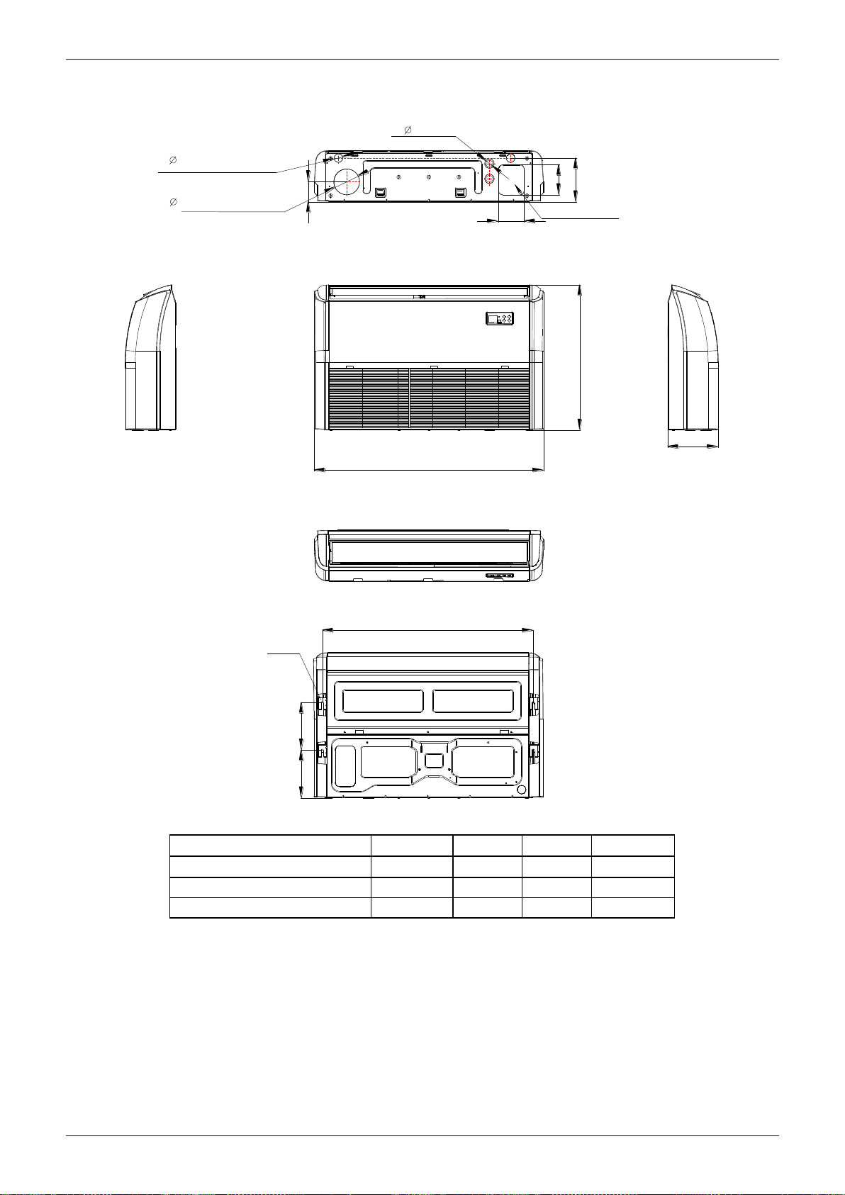
Dimensions
A
B
220
222
C
120
2- 4 0
120
140
2- 3 3
W ir in g c o n n e ctio n p ort
204
94
F re s h a ir in ta k e
D r a i n d i s c ha r g e p o rt
R e fr ig e r a nt p ip e h ole
H a n g in g a r m
D
Capacity (KBtu/h)
A B C
D
18/24
1068
675
235
983
30
1285
675
235
1200
36/42/48/55
1650
675
235
1565
2. Dimensions
Indoor Units 54
Page 57

Service Space
3. Service Space
Indoor Units 55
Page 58

Wiring Diagrams
4. Wiring Diagrams
MUE-18HRFN1-QRD0, MUE-24HRFN1-QRD0, MUE-30HRFN1-QRD0, MUE-36HRFN1-QRD0
MUE-42HRFN1-QRD0, MUE-48HRFN1-QRD0, MUE-55HRFN1-QRD0
Indoor Units 56
Page 59

Electric Characteristics
Model
Indoor Units
Power Supply
Hz
Voltage
Min.
Max.
MFA
MUE-18HRFN1-QRD0
50
220-240V
198V
254V
/
MUE-24HRFN1-QRD0
50
220-240V
198V
254V
/
MUE-30HRFN1-QRD0
50
220-240V
198V
254V
/
MUE-36HRFN1-QRD0
50
220-240V
198V
254V
/
MUE-42HRFN1-QRD0
50
220-240V
198V
254V
/
MUE-48HRFN1-QRD0
50
220-240V
198V
254V
/
MUE-55HRFN1-QRD0
50
220-240V
198V
254V
/
M icro p hon e
1m
1m
A ir o u tle t sid e
1 .5 m
1m
M ic ro p hone
Model
Sound Power
dB (A)
Noise level dB(A)
H M L
MUE-18HRFN1-QRD0
56
44
39
34
MUE-24HRFN1-QRD0
64
53
48
42
MUE-30HRFN1-QRD0
65
54
49
44
MUE-36HRFN1-QRD0
65
56
53
50
MUE-42HRFN1-QRD0
68
56
48
41
MUE-48HRFN1-QRD0
68
56
48
41
MUE-55HRFN1-QRD0
70
55
50
45
5. Electric Characteristics
Note:
MFA: Max. Fuse Amps. (A)
6. Sound Levels
Ceiling Floor
Indoor Units 57
Page 60

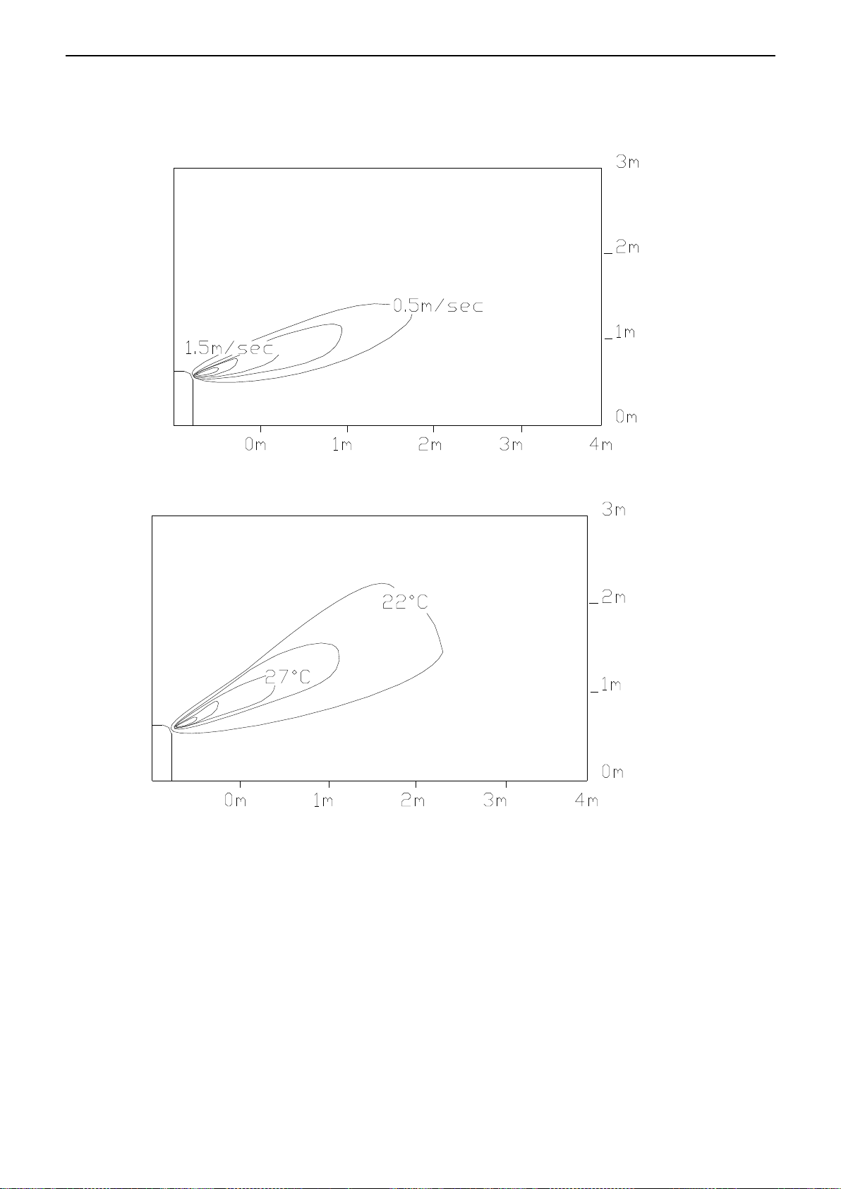
Air Velocity and Temperature Distributions (Reference Data)
7. Air Velocity and Temperature Distributions (Reference Data)
Model: MUE-18HRFN1-QRD0, MUE-24HRFN1-QRD0
Ceiling installation:
Discharge angle 17°
Discharge angle 50°
Indoor Units 58
Page 61

Air Velocity and Temperature Distributions (Reference Data)
Floor installation:
Discharge angle 17°
Discharge angle 50°
Indoor Units 59
Page 62

Air Velocity and Temperature Distributions (Reference Data)
Model: MUE-30HRFN1-QRD0, MUE-36HRFN1-QRD0
Ceiling installation:
Discharge angle 17°
Discharge angle 50°
Indoor Units 60
Page 63

Air Velocity and Temperature Distributions (Reference Data)
Floor installation:
Discharge angle 17°
Discharge angle 50°
Indoor Units 61
Page 64

Air Velocity and Temperature Distributions (Reference Data)
Model: MUE-42HRFN1-QRD0, MUE-48HRFN1-QRD0, MUE-55HRFN1-QRD0
Ceiling installation:
Discharge angle 17°
Discharge angle 50°
Indoor Units 62
Page 65

Air Velocity and Temperature Distributions (Reference Data)
Floor installation:
Discharge angle 17°
Discharge angle 50°
Indoor Units 63
Page 66

Accessories
Name
Shape
Quantity
Remote controller & Its
holder(The product you
have might not be
provided the following
accessories)
1. Remote controller
1
2. Remote controller holder
1
3. Mounting screw (ST2.9×10-C-H)
2
4. Alkaline dry batteries (AM4)
2
Others
5. Owner's manual
1
6. Installation manual
1
7. Remote controller manual
1
Model(Btu/h)
18000-24000
30000
36000
36000
POWER
Phase
1-phase
1-phase
1-phase
3-phase
Frequency and
Voltage
220-240V, 50Hz
220-240V, 50Hz
220-240V, 50Hz
380-415V, 50Hz
POWER
WIRING (mm2)
3×2.5
3×2.5
3×4.0
5×2.5
CIRCUIT BREAKER/Fuse (A)
30/20
40/30
40/30
30/20
Indoor/Outdoor Connecting Wiring
(Weak Electric Signal) (mm2)
2×0.2
2×0.2
2×0.2
2×0.2
Indoor/Outdoor Connecting Wiring
(Strong Electric Signal) (mm2)
3×1.0
3×1.0
3×1.0
3×1.0
Model(Btu/h)
42000~48000
42000~60000
POWER
Phase
1-phase
3-phase
Frequency and Voltage
220-240V, 50Hz
380-415V, 50Hz
Power Wiring (mm2)
3×4.0
5×2.5
Circuit Breaker/Fuse (A)
40/35
30/25
Indoor/Outdoor Connecting Wiring(Weak Electric Signal) (mm2)
2×0.2
2×0.2
Indoor/Outdoor Connecting Wiring(Strong Electric Signal) (mm2)
3×1.0
3×1.0
8. Accessories
9. The Specification of Power
Indoor Units 64
Page 67

Field Wiring
10.Field Wiring
Indoor Units 65
Page 68

Four-way Cassette Type (Compact)
Four-way Cassette Type (Compact)
1. Features ........................................................................................ 67
2. Dimensions ................................................................................... 69
3. Service Space................................................................................ 70
4. Wiring Diagrams ................................................................ ............ 71
5. Air Velocity and Temperature Distributions (Reference Data)........ 72
6. Electric Characteristics ................................................................. 73
7. Sound Levels................................ ................................................. 73
8. Accessories ................................................................................... 74
9. The Specification of Power............................................................ 74
10. Field Wiring ................................................................................. 75
Indoor Units 66
Page 69

Features
1. Features
1.1 New panel
360°surrounding air outlet design, affords comfortable feeling
1.2 Compact design
The body size is 570×260×570mm, it’s just smaller than the ceiling board, so it’s very easy for
installation and will not damage the decoration. The panel size is 647×50×647mm.
The hooks are designed in the four corners of the body, which can save installation space.
1.3 Electric control box built-in design
The E-box is simply and safely built inside the indoor unit. It’s convenient for installation and
maintenance. Can check the control part easily, you only need to open the air return grille.
1.4 Air passage function
Reserves the space for air outlet from the side of indoor unit; It’s availed to connect air duct
from the two sides to the nearby small rooms.
Indoor Units 67
Page 70

Features
Indoor Units 68
Page 71

Dimensions
P a n el
G a s s ide
Liq uid s ide
4-in s t a ll h a n ger
B o d y
D ra in pip e32
Fres h a ir inta ke
65
647
647
50
D ra in ho le
( fo r S e rv ice )
545
570
260
68
42
157
126
44
W irin g c o nne c tio n p ort
75
150
D istr ibu tio n d uct
2-
E -p a r ts b ox
4-S c re w h ole
(fo r in s t a ll p a n el)
523
570
W irin g c o nne c tio n p ort
170
2-
2. Dimensions
MCA3U-12HRFN1-QRD0W, MCA3-18HRFN1-QRD0
Indoor Units 69
Page 72

Service Space
3. Service Space
Indoor Units 70
Page 73

Wiring Diagrams
4. Wiring Diagrams
MCA3U-12HRFN1-QRD0W
MCA3-18HRFN1-QRD0
Indoor Units 71
Page 74

Air Velocity and Temperature Distributions (Reference Data)
A irflo w v e lo city
T e m p era ture
5. Air Velocity and Temperature Distributions (Reference Data)
Indoor Units 72
Page 75

Electric Characteristics
Model
Indoor Units
Power Supply
Hz
Voltage
Min.
Max.
MFA
MCA3U-12HRFN1-QRD0W
50
220-240V
198V
254V
/
MCA3-18HRFN1-QRD0
50
220-240V
198V
254V
/
1 . 4 m
M ic r o p h on e
Model
Noise Power dB(A)
Noise level dB(A)
H M L
MCA3U-12HRFN1-QRD0W
58
42
38
34
MCA3-18HRFN1-QRD0
59
46
42
38
6. Electric Characteristics
Note:
MFA: Max. Fuse Amps. (A)
7. Sound Levels
Indoor Units 73
Page 76

Accessories
Name
Shape
Quantity
Installation Fittings
Installation paper board
1
Tubing & Fittings
Soundproof / insulation sheath
1
Drainpipe Fittings
Out-let pipe sheath
1
Out-let pipe clasp
1
Drain joint
1
Seal ring
1
Remote controller & Its
Frame(The product you
have might not be
provided the following
accessories)
Remote controller & Its Frame
1
Remote controller holder
1
Mounting screw(ST2.9×10-C-H)
2
Remote controller manual
1
Alkaline dry batteries (AM4)
2
Others
Owner's manual
1
Installation manual
1
Installation accessory
(The product you have
might not be provided the
following accessories
Expansible hook
4
Installation hook
4
Orifice 1
Model(Btu/h)
12000
18000
POWER
Phase
1-phase
1-phase
Frequency and Voltage
220-240V, 50Hz
220-240V, 50Hz
POWER WIRING (mm2)
3×2.5
3×2.5
CIRCUIT BREAKER/Fuse (A)
20/16
30/20
Indoor/Outdoor Connecting Wiring(Weak Electric Signal) (mm2)
2×0.2
Indoor/Outdoor Connecting Wiring(Strong Electric Signal)(mm2)
4×1.0
3×1.0
8. Accessories
9. The Specification of Power
Indoor Units 74
Page 77

Field Wiring
10. Field Wiring
MCA3U-12HRFN1-QRD0W
MCA3-18HRFN1-QRD0
Indoor Units 75
Page 78

Console Type
Console Type
1. Features ........................................................................................ 77
2. Dimensions ................................................................................... 80
3. Service Space................................................................................ 81
4. Wiring Diagrams ................................................................ ............ 82
5. Air Velocity and Temperature Distributions (Reference Data)........ 83
6. Electric Characteristics ................................................................. 84
7. Sound Levels................................ ................................................. 85
8. Accessories ................................................................................... 86
9. The Specification of Power............................................................ 86
10. Field Wiring ................................................................................. 87
Console Type 76
Page 79

Features
1. Features
1.1. Modern and elegant appearance
The simple and stylish designs can nicely harmonies with your living space.
1.2. Four panels optional
1.3. Two air-outlet ways
Cooling mode
Quick Cooling To maintain room temp
Air outlet from top and bottom to make quick cooling ------When the A/C is just switched on, or room
temperature is still high, cold air will be blown out from top and bottom air outlet to cool down the room
quickly
Air outlet from top to maintain room temperature ----When the room has been cooled down, or the A/C
has been opened over 1 hour, cold air only from the top outlet to keep constant room temp
Heating mode
Console Type 77
Page 80

Features
Anti-cold air ------When the AC is just turn on, temperature of evaporator is very low, in this case, in
order to prevent cold air direct blowing, only the upper louver is opened in a high position, the lower
louver closed.
1.4. Four air inlets
1.5. Low noise
DC indoor fan motor, which has five speeds.
Low noise and energy saving.
Advanced centrifugal fan technology makes a fast airflow and reduces the indoor noise.
1.6. Golden fin is optional.
Console Type 78
Page 81

Features
1.7. Active carbon filter is standard.
Console Type 79
Page 82

Console Type
16 D ra in p ipe
195
H ang ing a rm
U n it: m m
700
600
210
2. Dimensions
Console Type 80
Page 83

Console Type
3. Service Space
Console Type 81
Page 84

Console Type
4. Wiring Diagrams
MFAU-12HRFN1-QRC8W, MFA-16HRFN1-QRC8W
Console Type 82
Page 85
Console Type
A irflo w v e lo city
T e m peratu re
5. Air Velocity and Temperature Distributions (Reference Data)
Discharge angle 60
Console Type 83
Page 86

Console Type
Model
Indoor Units
Power Supply
Hz
Voltage
Min.
Max.
MFA
MFAU-12HRFN1-QRC8W
50
220-240V
198V
254V
/
MFA-16HRFN1-QRC8W
50
220-240V
198V
254V
/
6. Electric Characteristics
Console Type 84
Page 87

Console Type
1.5m
1m
M icrophone
Model
Noise Power
dB(A)
Noise level dB(A)
H M L
MFAU-12HRFN1-QRC8W
58
47
41
35
MFA-16HRFN1-QRC8W
58
48
41
35
7. Sound Levels
Console Type 85
Page 88

Console Type
Name
Shape
Quantity
Installation fittings
Hook 2
Remote controller & Its Frame
Remote controller
1
Frame 1
Mounting screw (ST2.9×10-C-H)
2
Alkaline dry batteries (AM4)
2
Others
Installation manual
/
1
Ow ner's manual
/
1
Model(Btu/h)
12000
16000
POWER
Phase
1-phase
1-phase
Frequency and Voltage
220-240V, 50Hz
220-240V, 50Hz
POWER WIRING (mm2)
3×2.5
3×2.5
CIRCUIT BREAKER/Fuse (A)
20/16
30/20
Indoor/Outdoor Connecting Wiring(Weak Electric Signal) (mm2)
Indoor/Outdoor Connecting Wiring(Strong Electric Signal)(mm2)
4×1.0
4×1.0
8. Accessories
9. The Specification of Power
Console Type 86
Page 89

Console Type
10. Field Wiring
Console Type 87
Page 90

M Floor-standing Type
M Floor-standing Type
1.Features ................................................................ ..... 89
2. Dimensions ............................................................... 90
3. Service Space............................................................ 91
4. Wiring Diagrams ........................................................ 92
5. Electric Characteristics ............................................. 94
6. Sound Levels............................................................. 95
7. Accessories................................ ............................... 96
8. The Specification of Power................................ ........ 97
9. Field Wiring ............................................................... 98
M Floor-standing Type 88
Page 91

Features
1. Features
1.1 Fashionable design, concise and easy design better suits decoration style.
1.2. Dustproof Air Outlet
When press OFF to turn off the unit, the air outlet louver can be closed automatically to prevent the dust
falling in.
1.3. Easy Control
Big LCD display shows multi-information very clearly.
Slight-touch buttons make the operation easy, clear and precise.
1.4. Comfortable Air Flow
Long distance air supply.
3D air distribution(Vertical and horizontal louvers auto swing)(optional)
1.5. Fresh Air (Optional)
A fresh air inlet can be customized on the return air channel. When the indoor fan runs, the fresh air will
be sucked inside through the fresh air pipe, which makes the air more clear and healthy.
1.6 Double Air Filters (Optional)
Various healthy filters are optional.
1.7 Ionizer (Optional)
Ionizer generator brings refreshing air to your room.
M Floor-standing Type 89
Page 92

Dimensions
Dimension
Model
W(mm)
D(mm)
H(mm)
MFM-24HRFN1-QRD0
500
315
1700
MFM-36HRFN1-QRD0
600
455
1934
MFM-48HRFN1-QRD0
600
455
1934
MFM-55ARFN1-RRD0
600
455
1934
H
W
D
2. Dimensions
M Floor-standing Type 90
Page 93

Service Space
3. Service Space
M Floor-standing Type 91
Page 94

Wiring Diagrams
4. Wiring Diagrams
MFM-24HRFN1-QRD0
MFM-36HRFN1-QRD0,MFM-48HRFN1-QRD0
M Floor-standing Type 92
Page 95

Wiring Diagrams
MFM-55ARFN1-RRD0
M Floor-standing Type 93
Page 96

Electric Characteristics
Model
Indoor Units
Power Supply
Hz
Voltage
Min.
Max.
MFA
MFM-24HRFN1-QRD0
50
220-240V
198V
254V
/
MFM-36HRFN1-QRD0
50
220-240V
198V
254V
10
MFM-48HRFN1-QRD0
50
220-240V
198V
254V
10
MFM-55ARFN1-RRD0
50
380-415V
342V
440V
25
5. Electric Characteristics
Note:
MFA: Max. Fuse Amps. (A)
M Floor-standing Type 94
Page 97

Sound Levels
1m
1m
M icrophone
Model
Sound Power
Level dB(A)
Noise level dB(A)
H M L
MFM-24HRFN1-QRD0
63
49
46
43
MFM-36HRFN1-QRD0
63
48
45
41
MFM-48HRFN1-QRD0
64
53
48
44
MFM-55ARFN1-RRD0
67
52
48
44
6. Sound Levels
M Floor-standing Type 95
Page 98

Accessories
NO.
Part Name
Shape
Quantity
1
Safety Lock
1
2
Self-tapping Screw 3.9×25
2
3
Flat Washers
2
4
Bushing-Sleeve Cover
1
5
Sound/Heat Insulation Sleeves
2
6
Seal 1
7
Drain joint 1
8
Pipe - hole - protection Ring
1
9
Remote Battery
2
10
Remote Controller
1
11
Remote controller manual
1
12
User's manual
1
13
Installation manual
1
14
Remote controller holder(Optional parts)
1
15
Ratproof board(on some models)
1
16
Band(on some models)
2
17
Drain Hose(on some models)
1
18
Connection Cables(on some models)
1
19
Putty(on some models)
1
7. Accessories
M Floor-standing Type 96
Page 99

The Specification of Power
Model(Btu/h)
24000
POWER
Phase
1-phase
Frequency and Voltage
220-240V, 50Hz
POWER WIRING (mm2)
3×2.5
CIRCUIT BREAKER/Fuse (A)
30/20
Indoor/Outdoor Connecting Wiring(Weak Electric Signal) (mm2)
2×0.2
Indoor/Outdoor Connecting Wiring(Strong Electric Signal)(mm2)
3×1.0
Model(KBtu/h)
36
36
48
48
Indoor Power
Phase
1-phase
1-phase
1-phase
1-phase
Frequency and
Voltage
220-240V, 50Hz
220-240V, 50Hz
220-240V, 50Hz
220-240V, 50Hz
Circuit Breaker/
Fuse (A)
15/10
15/10
15/10
15/10
Outdoor Power
Phase
1-phase
3-phase
1-phase
3-phase
Frequency and
Voltage
220-240V, 50Hz
380-415V, 50Hz
220-240V, 50Hz
380-415V, 50Hz
Circuit Breaker/
Fuse (A)
40/30
25/20
50/40
32/25
Indoor Unit Power Wiring (mm2)
3×1.5
3×1.5
3×1.5
3×1.5
Indoor/Outdoor Connecting
Wiring (mm2)
Ground Wiring
4.0
2.5
4.0
2.5
Outdoor Unit
Power Wiring
3×4.0
5×2.5
3×4.0
5×2.5
Strong Electric
Signal
Weak Electric
Signal
(2×0.2)
(2×0.2)
(2×0.2)
(2×0.2)
Model(Btu/h)
55
POWER
Phase
3-phase
Frequency and Voltage
380-415V, 50Hz
POWER WIRING (mm2)
5×2.5
CIRCUIT BREAKER/Fuse (A)
32/25
Indoor/Outdoor Connecting Wiring(Weak Electric Signal) (mm2)
2×0.2
Indoor/Outdoor Connecting Wiring(Strong Electric Signal)(mm2)
8. The Specification of Power
M Floor-standing Type 97
Page 100

Field Wiring
9. Field Wiring
MFM-24HRFN1-QRD0
MFM-36HRFN1-QRD0, MFM-48HRFN1-QRD0
M Floor-standing Type 98
 Loading...