

Page 1
Service Manual, 2017-02
1 / 31
Service Manual
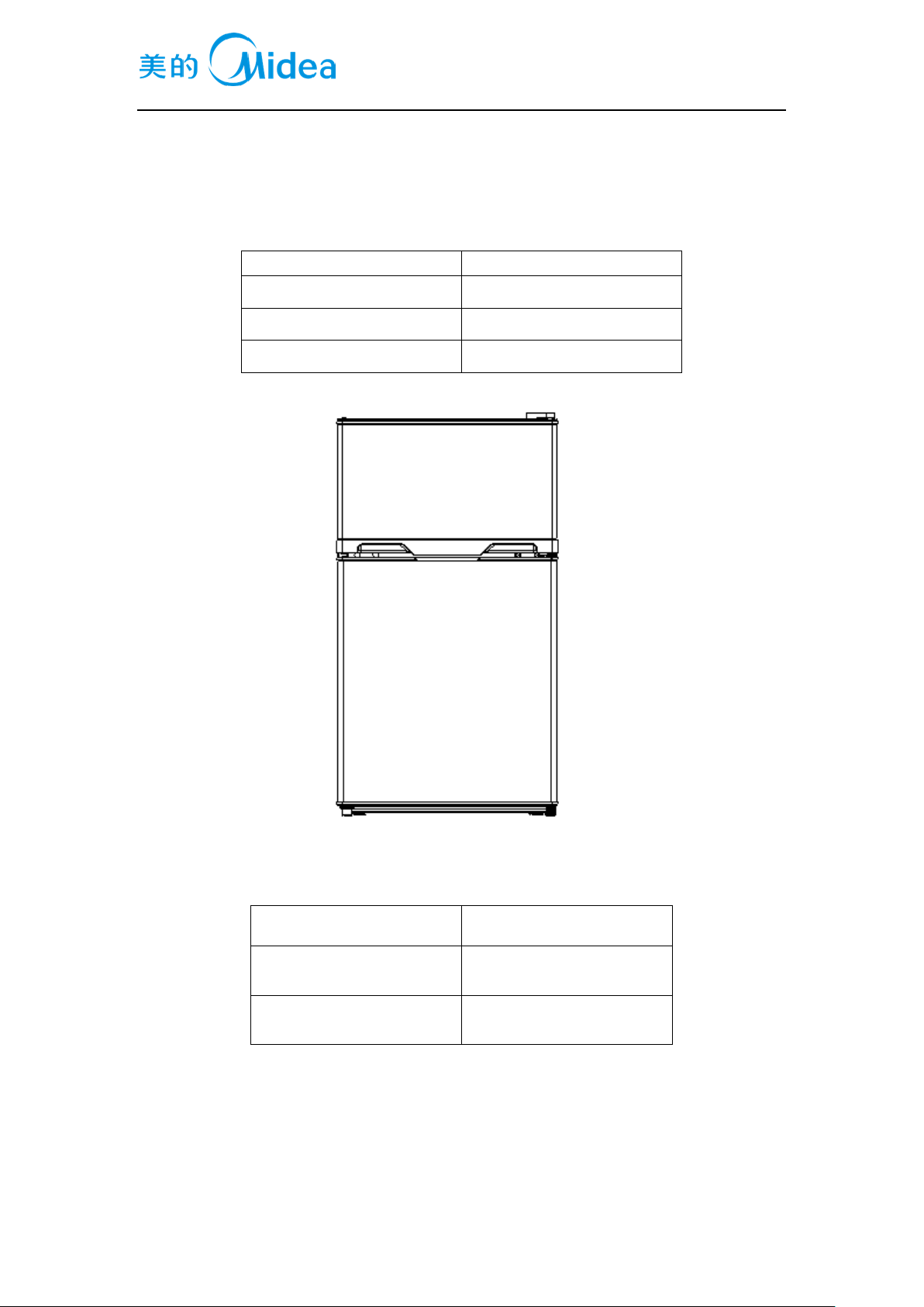
Applicable models
Model Code
CE-BCD87CM-SQ
22031020000524
SR-BCD87CM-OR
22031020000352
AR-BCD87CM-FR
22031020000085
(The picture is only for reference, and specific appearance and configuration are subject to the real
product)
Prepared by
R&D:Luo Xinjun
Reviewed by
QA:WangTao
SVC:ChenLei
Approved by
R&D:Tang Tao
SVC:GuangTaoshuai
Page 2
Service Manual, 2017-02
2 / 31
Important Safety Notice
The Maintenance Manual is only for the use of maintenance personnel with certain experience and
background in electrical, electronic and mechanical field.
Any attempt to repair main devices may lead to personal injury and property loss.
Manufacturers or distributors are not responsible for the content of the Manual and interpretation
thereof.
Midea Refrigerators
Technical Maintenance Manual
Copyright @2016
All rights reserved. Replication of all or part of the Manual in any forms shall not be allowed without
written approval by the Overseas Sales Corporation of Midea Refrigerators.
Page 3

Service Manual, 2017-02
3 / 31
Contents
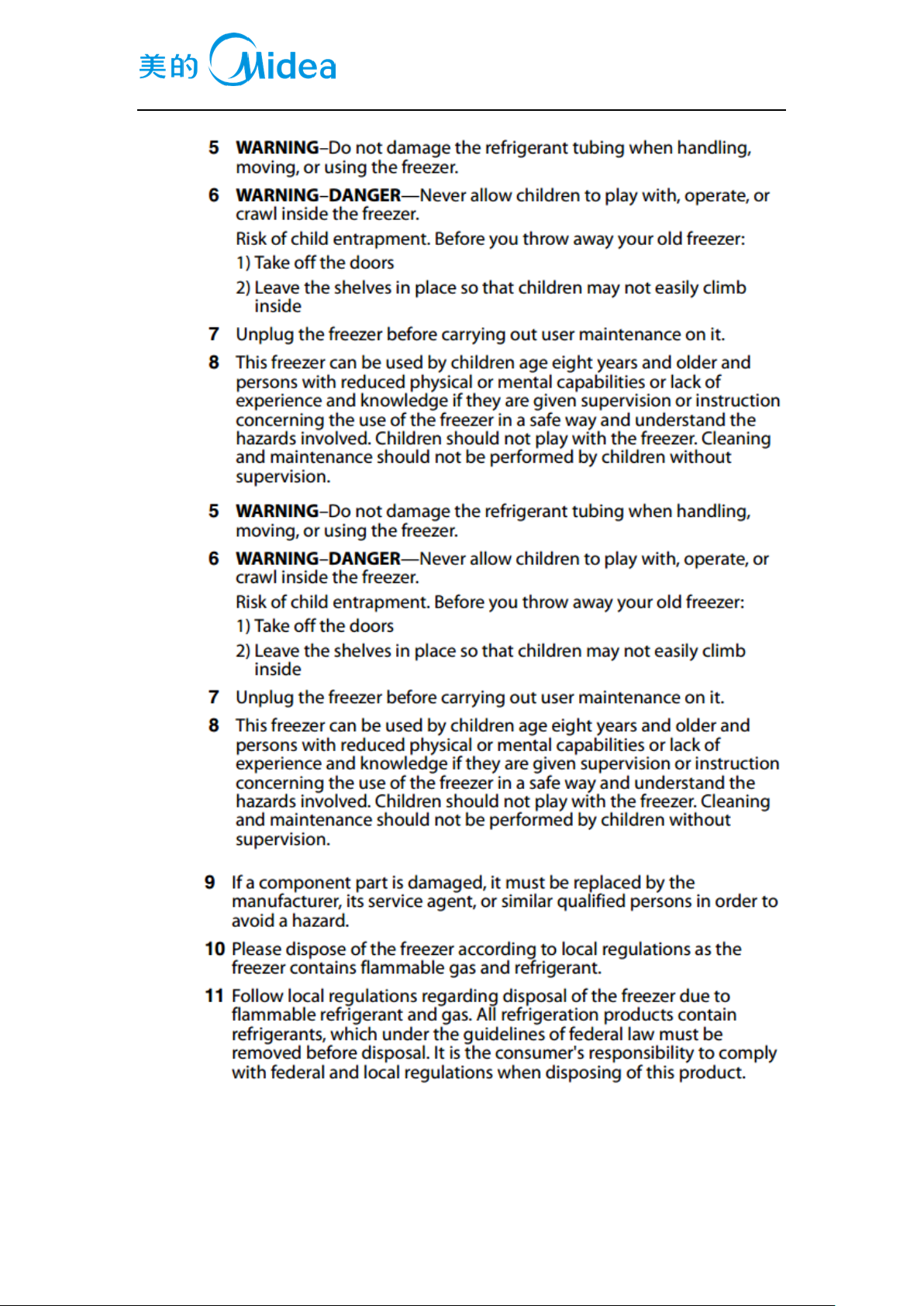
1.SAFETY WARNING CODE ......................................................................................................... 5
1.1WARNING FOR OPERATION SAFETY .................................................................................................. 5
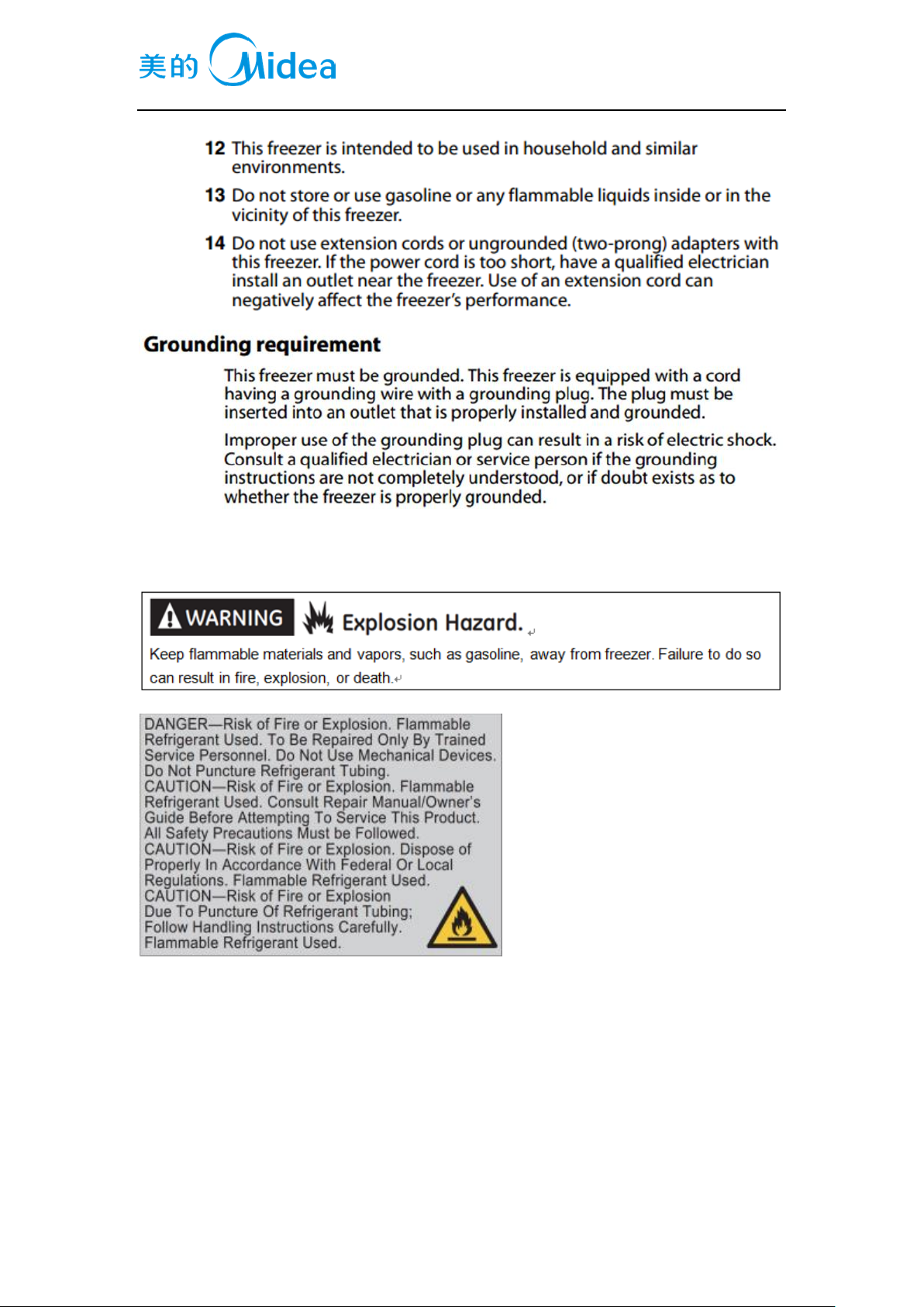
1.2SAFETY INSTRUCTION FOR REFRIGERANT ......................................................................................... 8
2.DESCRIPTION FOR PRODUCT FEATURES ............................................................................ 9
3.INSTALLATION AND COMMISSIONING .............................................................................. 10
3.1HANDLING ..................................................................................................................................... 10
3.2DISASSEMBLY (NONE) .................................................................................................................... 10
3.3 INSTALLATION LOCATION .............................................................................................................. 10
3.4 LEVELING OF THE REFRIGERATOR .................................................................................................. 10
3.5CHANGE THE DOOR OPENING DIRECTION ........................................................................................ 10
3.6 INSTALLATION OF HANDLE(NONE) ........................................................................................... 12
3.7 INSTALLATION OF DOOR LOCK(NONE) ........................................................................................... 12
3.8 ADJUSTMENT TO LEVEL THE DOOR(NONE) .................................................................................... 12
3.9 ADJUSTMENT TO SHELVES(NONE) ................................................................................................. 12
4.TERMS ........................................................................................................................................ 12
4.1 DEFINITION OF MODEL(NONE) ...................................................................................................... 12
4.2LOCATION OF NAMEPLATE .............................................................................................................. 12
5.PRODUCT SPECIFICATION .................................................................................................... 13
5.1 TYPESPECIFICATION(NONE) .......................................................................................................... 13
5.2 ELECTRICAL PARAMETERS ............................................................................................................. 13
5.3REFRIGERATING TEMPERATURE ...................................................................................................... 13
5.4DEFROSTING PARTS ........................................................................................................................ 14
5.5CIRCUIT DIAGRAM.......................................................................................................................... 14
6.INTERNAL VIEW AND DIMENSION ...................................................................................... 15
6.1MAIN PARTS AND THEIR NAMES ...................................................................................................... 15
6.2EXTERNAL DIMENSION ................................................................................................................... 16
7.REFRIGERATING PIPING SYSTEM AND CIRCULATING ROUTE OF COOLING AIR .. 17
7.1 REFRIGERATING PIPING SYSTEM .................................................................................................... 17
7.2CIRCULATING ROUTE OF COOLING AIR(NONE)................................................................................ 17
8. DISMANTLING OF PARTS ...................................................................................................... 17
8.1 PARTS ON THE DOOR ...................................................................................................................... 17
8.2 PARTS INSIDE THE REFRIGERATOR ................................................................................................. 18
8.3 LIGHT SYSTEM(NONE) ................................................................................................................... 18
8.4AIR DUCT COMPONENTS REFRIGERATINGCHAMBER ........................................................................ 18
8.5AIR DUCT COMPONENTS IN FREEZING CHAMBER AND FAN MOTOR.................................................. 19
Page 4

Service Manual, 2017-02
4 / 31
8.6EVAPORATOR AND TEMPERATURE SENSING SYSTEM ....................................................................... 19
8.6COMPRESSOR CASE ........................................................................................................................ 19
8.7DISPLAY AND MAIN CONTROL PANEL(NONE) .................................................................................. 20
8.8 BAR COUNTER(NONE) ................................................................................................................... 21
8.9 WATER DISPENSER(NONE) ............................................................................................................ 21
8.10 ICE MAKER(NONE) ...................................................................................................................... 21
9. FUNCTION AND OPERATION ................................................................................................ 22
9.1OPERATION PANEL .......................................................................................................................... 22
9.2TEMPERATURE CONTROL ................................................................................................................ 22
9.3GIVE AN ALARM(NONE) ................................................................................................................. 22
9.4FAILURE CODE AND SOLUTIONS(NONE) ......................................................................................... 22
9.5DEFROST FUNCTION ....................................................................................................................... 22
9.6COMPRESSOR FAN CONTROL(NONE) .............................................................................................. 22
9.7TEST MODE (NONE) ........................................................................................................................ 22
9.8SELF-DIAGNOSIS (NONE) ................................................................................................................ 22
10.CIRCUIT DESCRIPTION ........................................................................................................ 23
10.1 POWER SUPPLY(NONE) ................................................................................................................ 23
10.2 TEST CIRCUIT FOR DOOR SWITCH(NONE) ..................................................................................... 23
10.3 TEMPERATURE TEST CIRCUIT(NONE) ........................................................................................... 23
10.4FREEZER CHAMBER FAN MOTOR CIRCUIT (NONE) ......................................................................... 23
10.5REFRIGERATING CHAMBER FAN MOTOR CIRCUIT (NONE) .............................................................. 23
10.6CONDENSATION FAN CIRCUIT (NONE) .......................................................................................... 23
10.5 FAN MOTOR CIRCUIT OF THE VENTILATION DOOR(NONE) ............................................................ 23
10.6RESISTANCE VALUE OF THE SENSOR (R/T) (NONE) ....................................................................... 23
11.TROUBLESHOOTING METHOD........................................................................................... 24
11.1 NOT COOLING .............................................................................................................................. 24
11.2 NOT WORKING OF COMPRESSOR .................................................................................................. 25
11.3 -THERMOSTAT MALFUNCTION-UNDERCOOLING........................................................................... 26
11.4 NOISE .......................................................................................................................................... 26
12. FIGURES AND DETAILS OF REPAIR
PARTS(DOCUMENTSAREPROVIDEDSEPARATELY) ............................................................ 27
12.1FIGURES ....................................................................................................................................... 27
12.2LIST OF PARTS AND COMPONENTS ................................................................................................. 27
13APPENDIX: ................................................................................................................................ 27
13.1ELECTRICAL SCHEMATIC DIAGRAM(NONE) ................................................................................. 27
13.2REFRIGERATOR MAINTENANCE TOOLING AND EQUIPMENT AND MATERIAL ................................. 27
Page 5
Service Manual, 2017-02
5 / 31
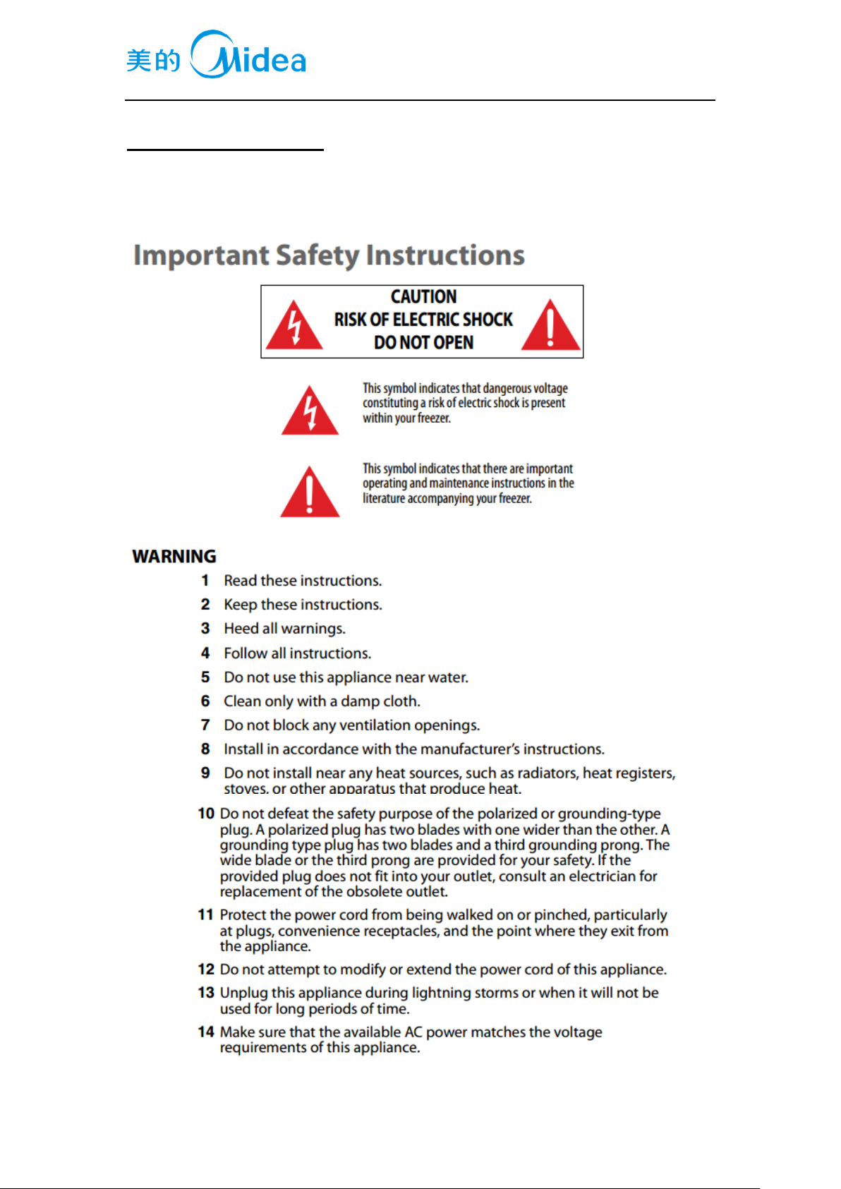
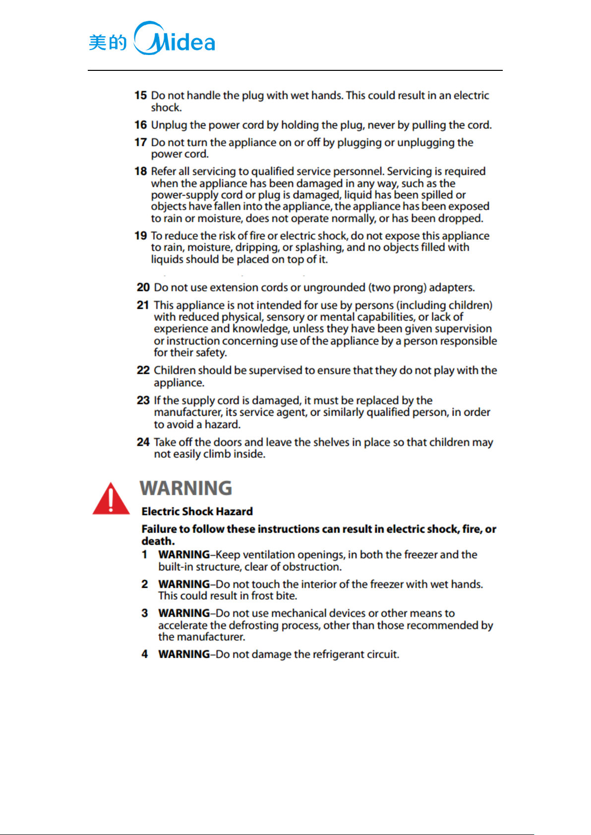
1.Safety Warning Code
1.1Warning for operation safety
Page 6
Service Manual, 2017-02
6 / 31
Page 7
Service Manual, 2017-02
7 / 31
Page 8
Service Manual, 2017-02
8 / 31
1.2Safety instruction for refrigerant
Page 9
Service Manual, 2017-02
9 / 31
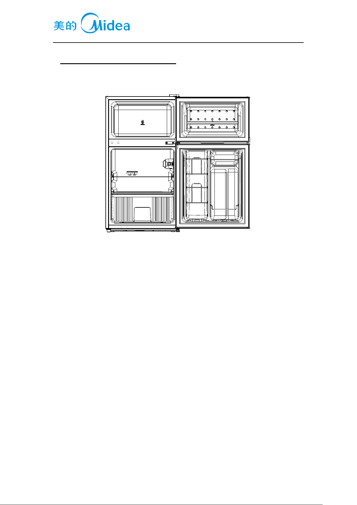
2.Description for product features
This product is provided with following features:
(The picture is only for reference, and specific appearance and configuration are subject to the real
product)
1) Mechanical temperature control
2) Manual defrost
3) Change the door opening direction
Page 10
Service Manual, 2017-02
10 / 31
3.Installation and commissioning
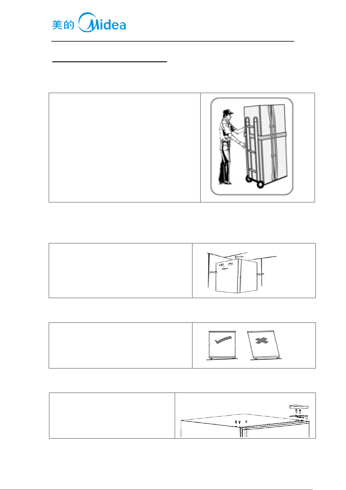
3.1Handling
1) Protecttherefrigeratorinmovingit
Sameasshownasleftphoto,pleasemoveitbyhandcartwi
thcushion
2) Removeallpackingmaterialsandbottomcushion,then
moveintohouseforplacement
3) Aftermovingittoappropriatelocation,waitfor2hoursbe
forepoweron.
3.2Disassembly (None)
3.3 Installation location
Location that is easy for ventilation shall be chosen
to facilitate heat dissipation, enhance its performance
and reduce the energy consumption.
3.4 Leveling of the refrigerator
If the refrigerator cannot be placed steadily, adjust
the footing to level it.
3.5Change the door opening direction
1) Remove the hinge cover.
Unscrew screws.
Remove the upper hinge, Insert pins and
hole cover.
Page 11

Service Manual, 2017-02
11 / 31
2) Remove the up door.
Unscrew screws.
Remove the middle hinge, Insert pins and
hole cover.
3) Remove the bottom door.
Unscrew screws and levelling feet.
Remove the lower hinge adjust feet
assembly.
4) Fix the levelling feet, lower hinge adjust
feet assembly and screws in the opposite
side.
5) Place the bottom door.
Place and fix the the middle hinge. Fix the
Insert pins and hole cover.
6) Place the up door.
Place and fix the the upper hinge. Fix the
hinge cover, Insert pins and hole cover.
7) Finish.
Page 12

Service Manual, 2017-02
12 / 31
3.6 Installation of handle(None)
3.7 Installation of door lock(None)
3.8 Adjustment to level the door(None)
3.9 Adjustment to shelves(None)
4.Terms
4.1 Definition of model(None)
4.2Location of nameplate
(The picture is only for reference, and specific appearance and configuration are subject to the real
product)
Page 13

Service Manual, 2017-02
13 / 31
5.Product specification
5.1 Typespecification(None)
5.2 Electrical parameters
Product Name
CE-BCD87CM-SQ
SR-BCD87CM-OR
AR-BCD87CM-FR
/
Product Code
22031020000524
22031020000352
22031020000085
/
Name
Item
Type
Specification
Specification
Specification
Specification
Compressor
Compressor
/
SZ55C1J
SZ45C1J-N
FZ45E1H-SL
/
Starter
PTC
8EA19C1/QP2-15/
QP2-15
8EA19C1/QP2-15/
QP2-15
QP2-4R7
/
Overload
protector
OLP
3TM117TF2/DRB1
2T61A1
3TM129TF2/DRB1
3T61A1
4TM222TFBYY/3T
M222TF2DRB25T6
1A1/BT68-140A61
D3
/
Winding resistance
of compressor
wiring terminal
Rmc: 40.25±7%Ω
Rsc: 15.89±7%Ω
Rms=Rmc+Rsc
Rmc: 34.24±7%Ω
Rsc: 16.53±7%Ω
Rms=Rmc+Rsc
Rmc: 10.1±7%Ω
Rsc: 9.6±7%Ω
Rms=Rmc+Rsc
/
Motor
Fan motor of the
freezing chamber
/ / / / /
Ventilation door of
the refrigerating
chamber
/ / / / /
Condensation fan
/ / / / /
Lights inside
the refrigerator
Lights inside the
freezing chamber
/ / / / /
Lights inside the
refrigerating
chamber
/
240V/10W
240V/10W
110V/10W
/
Switch of the
refrigerator door
/
Sector
Sector
Sector
/
5.3Refrigerating temperature
Temperature tolerance ≤ 2
o
C
Compartment
The highest (
o
C)
Lowest (
o
C)
Freezing
-12
-24
Refrigerating
10
0
Variable temperature
/
/
Page 14

Service Manual, 2017-02
14 / 31
5.4Defrosting parts
Defrosting period
Initial defrosting period
Normal defrosting period
/
/
Defrosting sensor
/
/
Defrosting temperature controller
/
/
Thermal fuse
/
/
Defrosting heater in freezing chamber
/
/
5.5Circuit diagram
Page 15

Service Manual, 2017-02
15 / 31
6.Internal view and dimension
6.1Main parts and their names
1
2
3
4
5
6
11
10
9
8
7
(The picture is only for reference, and specific appearance and configuration are subject to the real
product)
Freezer chamber
Refrigerator chamber
1. Toolbar
2. Steel column strip
3. Zip-top can steel bar
4. Zip-top can steel bar
5. Steel column strip
6. Steel column strip
7. Fruits and vegetables box
8. Glass shelf assembly
9. Glass shelf assembly
10. Ice box
11. Temperature-control box assembly
Page 16

Service Manual, 2017-02
16 / 31
6.2External dimension
Front view
Side view
Down view
Maximum open angle of door(180°)
(The picture is only for reference, and specific appearance and configuration are subject to the real
product)
Page 17

Service Manual, 2017-02
17 / 31
7.Refrigerating piping system and circulating route of cooling air
7.1 Refrigerating piping system
Compressor→condenser→Dry filter→Capillary tube→Evaporator→Return pipe→Compressor
(The picture is only for reference, and specific appearance and configuration are subject to the real
product)
7.2Circulating route of cooling air(None)
8. Dismantling of parts
8.1 Parts on the door
Door seal
Page 18

Service Manual, 2017-02
18 / 31
Door seal is installed into door liner groove.
1) Open the refrigerator door;
2) Take the door seal out of door liner;
Guardrail
Picture direction,move to one side,take out the other
side.
8.2 Parts inside the refrigerator
Shelves
1) move up
2) outward pulling the shelve at
horizontal
Drawer
1) outward pulling the drawer at
horizontal
8.3 Light system(None)
8.4Air duct components refrigeratingchamber
Air duct components refrigeratingchamber
None
Page 19

Service Manual, 2017-02
19 / 31
8.5Air duct components in freezing chamber and fan motor
Disassembly and installation of Air duct
None
Fan motor of air duct
None
8.6Evaporator and temperature sensing system
Evaporator in freezing chamber
not replace
Components on the evaporator
Defrost thermostat
None
Fuse
None
Defrost sensor
None
Defrost heater
None
Evaporator in refrigerating chamber
None
Components on the evaporator
None
Sensor
Sensor in freezing chamber
None
Sensor in refrigerating chamber
None
Sensor in Variable temperature chamber
None
ambient temperature senser
None
Thermostat
Remove the lamp cover and insert pin, remove the screw
under insert pin, outward pulling the thermostat-control
box at horizontal
pull out the knod,remove the socket the terminal,replace
the thermostat
8.6Compressor case
Piping system in the compressor case
Page 20

Service Manual, 2017-02
20 / 31
1.compressor
2.left condenser
3.dry filter
4.suction pipe
5.right condenser
Starter and protector of the compressor
1. Remove the screws
1) Two screws outside
2) One screw inside
2. Remove the clipping strip
Slowly pull it out
3. Remove the protective cover
1)Pry the protective cover slowly from the upper part,
2)Pull it out and remove it.
4. Remove the starter and protector
Unplug the starter and protector (you can use a
screwdriver to pry it slowly)
5. The reverse process can complete installation.
8.7Display and main control panel(None)
Display control board
None
Main control board
None
1
2
3
4
5
Page 21

Service Manual, 2017-02
21 / 31
8.8 Bar counter(None)
Disassembly and installation of bar counter
None
Disassembly and installation bar doorseal
None
8.9 Water dispenser(None)
Disassembly and installation of water valve
None
Disassembly and installation of water tank
None
8.10 Ice maker(None)
Disassembly and installation of ice maker
None
Disassembly and installation of water system
None
Disassembly and installation ice machine sensor
None
Page 22

Service Manual, 2017-02
22 / 31
9. Function and operation
9.1Operation panel
Direct cooling mechanical refrigerator, through the thermostat knob to adjust the stalls.
9.2Temperature control
Turn the temperature control knob to MAX, the internal temperature of the refrigerator becomes
lower.
Turn the temperature control knob to MIN, the internal temperature of the refrigerator becomes
higher.
NOTE:Please adjusting and using between "MAX"and"MIN"
9.3Give an alarm(None)
9.4Failure code and solutions(None)
9.5Defrost function
Manual defrost
9.6Compressor fan control(None)
9.7Test mode (None)
9.8Self-diagnosis (None)
Page 23

Service Manual, 2017-02
23 / 31
10.Circuit description
10.1 Power Supply(None)
10.2 Test circuit for door switch(None)
10.3 Temperature test circuit(None)
10.4Freezer chamber fan motor circuit (None)
10.5refrigerating chamber fan motor circuit (None)
10.6Condensation fan circuit (None)
10.5 Fan motor circuit of the ventilation door(None)
10.6Resistance value of the sensor (R/T) (None)
Page 24

Service Manual, 2017-02
24 / 31
11.Troubleshooting Method
11.1 Not cooling
Page 25

Service Manual, 2017-02
25 / 31
11.2 Not working of compressor
Page 26

Service Manual, 2017-02
26 / 31
11.3 -Thermostat malfunction-Undercooling
11.4 Noise
Page 27

Service Manual, 2017-02
27 / 31
12. Figures and details of repair parts(Documentsareprovidedseparately)
12.1Figures
12.2List of parts and components
13Appendix:
13.1Electrical Schematic Diagram(None)
(Model:***)
13.2Refrigerator maintenance tooling and equipment and material
Tooling
No.
Name
Photo
Main Usage
1
Phillips screwdriver
screw assemble and disassemble
2
slotted screwdriver/scraper
screw and rivet assemble and
disassemble
3
Socket spanner 5/16″
hinge and compressor screw
assemble and disassemble
4
Sucker
display panel and air duct
cover disassemble
Page 28

Service Manual, 2017-02
28 / 31
5
Allen wrench(2.8~4mm)
handle assemble and
disassemble
6
Vise grip pliers
sealing process tube
7
Pipe cutter
pipe cutting
8
Knife
assistive tool
9
Nipper pliers
assistive tool
10
Capillary tube scissors
Shear capillary
Equipment
No.
Name
Photo
Main Usage
Page 29

Service Manual, 2017-02
29 / 31
1
Vacuum pump
vacuum pumping
2
Electronic scale
weighing refrigerant/gas
3
High pressure nitrogen with
piezometer
pipe and cooling
system(condenser, evaporator,
etc) impurities clean
4
Soldering gun
heating and welding
5
Quick coupling
connection process pipeline,
vacuum or charge refrigerant wi
ll be used.
6
hand leak detector
welding point leakage detect, if
no, use soap-suds
material
No.
Name
Photo
Main Usage
Page 30

Service Manual, 2017-02
30 / 31
1
Process pipeline
Chargetherefrigerant
2
Dry filter
Involving a system failure to be
replaced
3
Copper welding rod
tube welding
4
Refrigerant/gas
Add refrigerant to the system
5
Sealing tape
door fixing for reversible door
option
Page 31

Service Manual, 2017-02
31 / 31
Midea Refrigerators
If you need to get detailed technical information from the manufacturer, please contact:
xxx@midea.com
Refrigeration Division
Overseas Sales Company
Address: No. 176, Jinxiu Avenue, Economic-Technological Development Area, Hefei, Anhui,
China
 Loading...