

Page 1
Midea Drum Washing Machine
Service Manual
Sicily Glory (6.0/7.0/8.0kg)
Page 2

1 ….........................................…………………............
2 INTRODUCTION ………………....................…...........…..
2.1 C …………………….…………………………………….....
2.2 ………………….…………………………………………………...
2.3 ……………………………………………………............
2.4 …………………………………………………............
2.5 Introduction ……………….…………………………………………..
2.6 …………………………………………………………………………...
2.7F of s ……………………..........................................................
2.7.1 of a ……………………………………………………….
2.7.2 F ofa ……………………………………..…..
2.7.3 F of b ……………………………………………………....
2.7.4 F of …………………………………………………….…....
2.7.5 F of c ……………………………………………………………..
2.7.6 m …………………………………………………………………..
2.7.7 F of m ………………………………………..…….....
3 ………………………………………………………………………........
3.1 ……………………………………………………….....…………..
3.2 ……………………………………………………..……..…...
3.3 ……………………………………………………………...………………..
3.4 …………………………………………………………...………….
3.5 …………………………………………………………...……….…..
3.6 …………………………………………………………..……….
3.7 ……………………………………………………….....
4. …………………………………………………..
4.1 …………………………………………………………………………….
4.2 ………………………………………………………………………...
4.3 ………………………………………………………………………..
4.4 ……………………………………………………………………………….
4.5 ……………………………………………………………………………..
4.6 ……………………………………………………………………………….
4.7 ………………………………………………………………………...….
4.8 ……………………………………………………………..……..……..…….
4.9 ………………………………………………………………..…..
4.9.1 …………………………………………………………………..…....
4.9.2 .....................................................................................................
4.10 ............................................................................................
4.11 ......................................................................................................
SAFETY PRECAUTION
OF WASHING MACHINE
haracteristics of product
Working principle
Summary model of product
Exploded view & List of parts
of control panel
Basic function
unction afety guard
Function void overflow
unction void heating without water
unction ubble checking
unction auto-balance
unction hild lock
Program emory
unction otor self-protection
INSTALLATION
Select the location
Remove transport bolts
Adjust leg
Connect inlet pipe
Place outlet hose
Electrical connection
Installing and checking items
OVERVIEW OF MAIN COMPONENTS
Top cover kit
Drawer panel kit
Control panel kit
Front plate
Lower panel
Cabinet kit
Panel support
Absorber
Drum tub assembly
Rear tub kit
Drum kit
Detergent box hose
Inlet system
. ........
5
6
6
6
7
8
13
14
15
15
15
15
16
16
16
16
16
17
17
17
18
18
18
19
20
20
20
21
21
21
22
22
23
23
23
24
24
25
P.02
TABLE OF CONTENTS
Page 3

28
28
28
28
28
29
29
29
29
30
31
33
34
35
35
36
36
36
36
37
37
37
38
38
39
39
40
40
40
41
41
41
42
42
42
43
43
28
4.12.2 ..................................................................................................
4.12.3 ........................................................................................
4.13 ....................................................................................................
4.13.1 .........................................................................................
4.13.2 .................................................................................................
4. 14 ...........................………………..............………………………….…….
4.15 ...........................………………..............…………………………………..
4.16 ...........................………………..............………………………….……
4.17 ...........................………………................................….
4.18 ...........................………………..............…………………………………...
4.19 ...........................………………..............…………………………………….
4.20 ...........................………………..............……………………………....
4.21 ...........................………………..............……………………………….…..
4.22 ...........................………………..............……………………………....
4.23 ...........................………………..............……………………....
5 ...........................………………..............…….
5.1 ...........................………………..............……………………..
5.2 ...........................………………..............……………………….
5.3 ...........................………………..............…………………..
5.4 ...........................………………..............…………………….
5.5 ...........................………………..............………………………
5.6 ...........................………………..............………………….….
5.7 ...........................………………..............………………………….
5.8 ...........................………………..............………………….….
5.9 ...........................………………..............………………….
5.10 ...........................………………..............……………………
5.11 ...........................………………..............……...……….
5.12 ...........................………………..............……………………..….
5.13 ...........................……………….......……………...
5.14 ...........................………………..............…………..……...
5.15 ...........................………………..............…………………………..
5.16 ...........................………………..............…………….……..
5.17 ...........................………………..............…………………….…..
5.18 ...........................……………..………………...
5.19 ...........................………………..............……………..……..
5.20 ...........................………………..............………………...
5.21 ...........................………………..............…………...
4.12.1 ..............................................................................................Pressure switch
Inlet valve
Detergent box kit
Drain system
Drainage system
Drain pump
Door kit
Gasket
Door lock
NTC temperature sensor
Heater
Filter
Condenser
Motor
PCB panel
Main harness assy
UNPACKING WAYS OF MAIN PARTS
Undo the back cover
Undo the top cover
Undo the control panel
Undo the lower panel
Undo the door lock
Undo the front panel
Undo the gasket
Undo the PCB panel
Undo the detergent box
Undo the inlet valve
Undo the pressure switch
Undo the pulley
Undo the upper counterweight
Undo the absorber pin
Undo the filter
Undo the drain pump
Undo the heater
Undo the NTC temperature sensor
Undo the door glass
Undo the panel support
Undo the drum tub assembly
P.03
TABLE OF CONTENTS
Page 4

5.22 ...........................………………..............……………………...
5.23 ...........................……….…………………………..
5.24 ...........................………………..............…………………………
6 ……...........................………………..............……………......
6.1 ...........................….....………………
6.2 ...........................………………..............……………………....
6.3 ...........................…….....…....…....…......
6.4 ...........................………..……………
6.5 ....................………………..............…………………………........
6.6 ...........................………………..............…………………………..........
6.7 ...........................………………..............…………………………….
7 T ...........................……………….....………………......
7.1 .......................……………………….…..
7.2 ...........................………………..............……………..
Undo the absorber
Undo the lower counterweight
Undo the motor
TROUBLESHOOTING
Circuit program & wiring connection figure
PCB wiring figure
Schedule of failure alarm & its disposal
Electrical parts working & testing principle
Service Mode
Fault tree
Service tools
ECHNICAL SPECIFICATION
Product technical specification parameter
Table of washing procedure
TABLE OF CONTENTS
44
44
44
45
45
46
47
48
53
55
63
64
64
65
P.04
Page 5

1.SAFETY PRECAUTION
P.05
1.Do not try to repair the machine by yourself. The machine may be damaged and its life
be shortened. What is worse, it will injure yourself.
2.Pull out its plug from the power socket before maintenance. Electricity!
3.Do not use several power plug with one socket.
To avoid fire, don’t use any socket with its actual current more than rated current.
4.Please check the power plug and socket whether damaged or not.
To avoid an electrical shock and fire, the power plug and socket should be replaced if
they are damaged.
.Don’t try to clean up the washing machine with water, or else, it’s possible to cause an
electrical shock or fire and shorten its life.
6.Forbid the harness contact with water for avoiding wet and don’t extend it during
maintenance. Don’t twist the harness to avoid it distorted.
7.Please clean up the dirt and dust on the surface of the cabinet, harness and connection
parts during maintenance.
Please avoid fire because of the electric leakage of harness.
8.Check electrical parts, harness whether they have become moist and replace them if
they are wet.
9.Check all parts of the machine and make sure to keep them in good condition after
maintenance.
10.Fasten upon the power plug and pullit out .
Be careful of a fire and electric shock when power cord is damaged.
11.Pull out its power plug when this machine doesn’t work.
Be careful of an electric shock and fire because of levin.
12.Don’t put tinder or sprayer beside the washing machine.
Be careful of a fire and explosion because of electric spark.
13.Don’t put a basin of water or wet clothes on the washing machine.
It is possible to cause an electric shock or fire if water from wet clothes leaks in to
the washing machine.
14.Do not place the washing machine in the place where it can be exposed to rain and
snow. Or else, it may cause an electric shock or fire, and therefore shorten its life.
15.Don’t press the button with sharp items such as nail, screw etc. Or else, it may cause
an electric shock or other damages.
16.This machine should be placed on the horizontal ground and installed correctly.
The machine is liable to shift on the gradient ground.
17.If the harness is damaged, it should be replaced completely.
18.It is necessary to put a mat on the floor and recline down the washing machine along
its side when repair it.
It is possible to damage the electrical components if the front of the washing machine
is placed at the ground.
19.During changing the heater of this machine, please check whether it is fixed on the
blanket correctly and whether the screw is fastened tight or not.
5
Page 6

2.INTRODUCTION OF PRODUCTS
P.06
2.1 haracteristics of product
It is the latest designed machine, which have many advantages such as fashion, large
rated washing capacity and large washing range. Specifically, its feature is as following:
1.Large washing range from cotton to wool and silk.
2.Gentle washing: no twist and little abrasion.
3.Electron auto-balance system, that is, the PCB panel controls the speed of spin and
ensures uniform distribution of clothes to reduce the wear of textile caused by its
vibration.
4.The drum of this machine is made of stainless steel of high quality and the cabinet is
durable.
5.The maximum temperature of washing water could be controlled independently and it
is up to 90℃.
6.Unique washing methods: rain, soak, throwing-knocking knead and so on, which can
wash clothes uniformly and improve washing performance.
7.Safety guard: water level control, door lock, child lock etc.
8.Anti-crease function: there is an automatic anti-crease and soak function in the
synthetic program, that’s, it doesn't drain at the end of washing and leave the clean
textile in the water of the drum to achieve the function of less crease.
9.Function of adjusting spin speed : select different spin speed according to textile.
10.Electronic water distribution system: The machine uses PCB to control the inlet valve
and distribute water properly at the different stages and dissolve detergent and softener
absolutely to improve washing performance.
2.2.Working principle
Drum washing machine wash clothes mainly in virtue of mechanical friction, chemical
force and temperature force. When the machine works, the motor runs clockwise several
seconds and runs anti-clockwise several seconds to drive the drum whose three lifters
hold up the clothes pressing against the inside of the drum. When clothes rise close to the
top, because the speed of motor is low and the centrifugal force is not enough to overcome
the gravity, clothes fall and impinge with washing liquid (like manual throwing-knocking
washing). The second force is the extrusion force of clothes (like manual extrusion). The
last force is the friction between clothes, clothes and lifters(like manual knead). To
improve washing performance, automatic drum washing machine could automatically
heat the washing liquid, whose temperature can be adjusted from 30℃ to 90℃. The high
temperature quickens the movement of the numerator of the washing liquid and speedups
C
Page 7
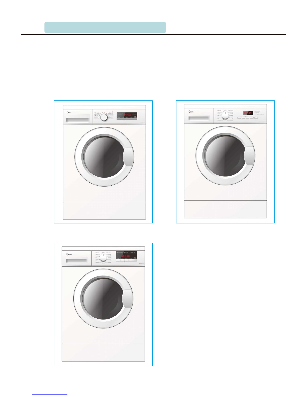
2.3 Summary model of product
P.07
G01
2.Overview of products2.INTRODUCTION OF PRODUCTS
the Chemical reaction. In a word, drum washing machine destroys bonding force between
dirt and clothes in virtue of intergraded force of water, detergent and mechanical force, to
clean away the dust.
G02
G03
Page 8
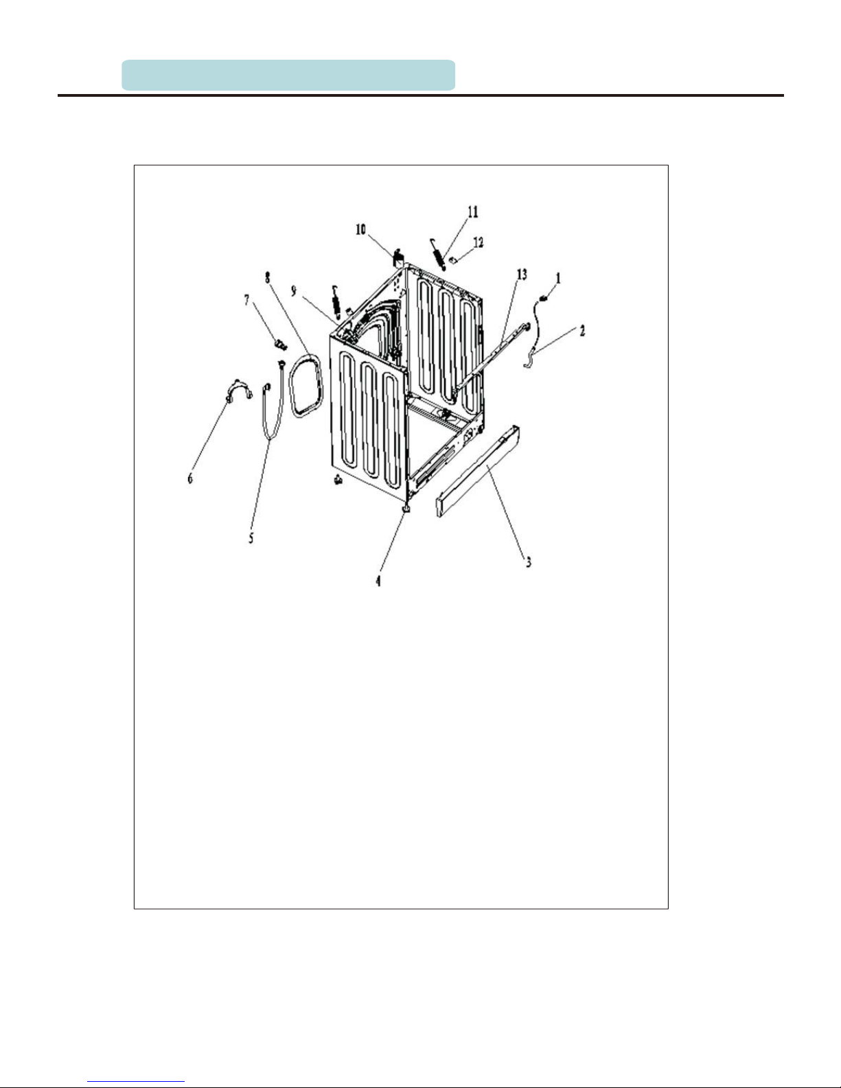
2.4 Explored & list of partsview
P.08
01 Pressure Switch
02 Chamber Pressure
03 Service Panel
04 Leg_Sub
05 Water_ Inlet_Pipe_Kit
06 The Bend Of Drain Hose
07 Transport Bolt Kit
Rear_ Cover
09 Water_ Inlet_ Valve
10 FILTER
11 Suspension Spring
12 Spring Hanger
13 Top_ Bracket
08
2.INTRODUCTION OF PRODUCTS
Page 9
P.09
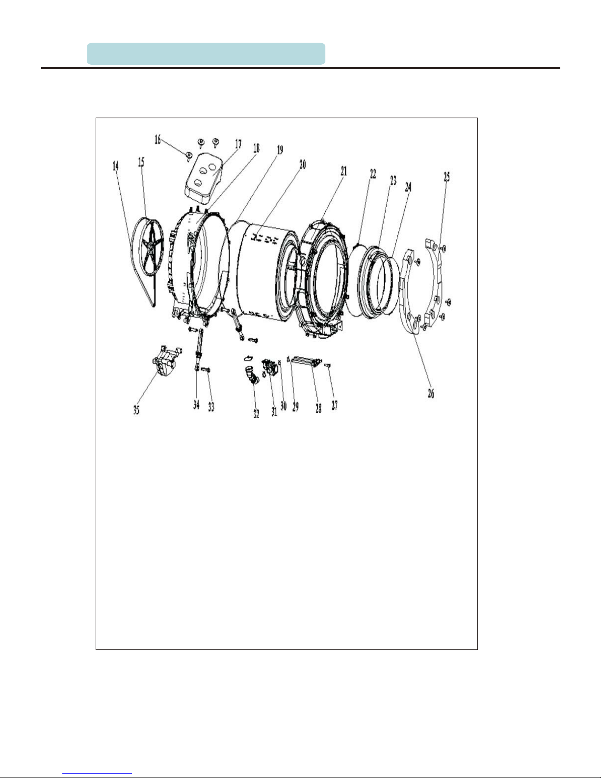
2.4 Explored & list of partsview
14 Belt
15 Driving_Pulley
16 Screw
17 Upper counterweight
18 Rear Tub
19 Tub_Seal
20 Drum Kit
21 Front_Tub
22
Inner Clamp
23 Gasket
24 Outer Gasket Clamp
2.INTRODUCTION OF PRODUCTS
25 Front_Right_Counterweight
26 Front_Left_Counterweight
27 NTC
28 Heater
29 Heating Brasket
30 Hose Clamp
31
Pump
32 Tub_Drain_Hose Kit
33 Damper_Pin
34 Damper
35 Motor
Page 10
P.10
2.Overview of products
2.4 Explored & list of partsview
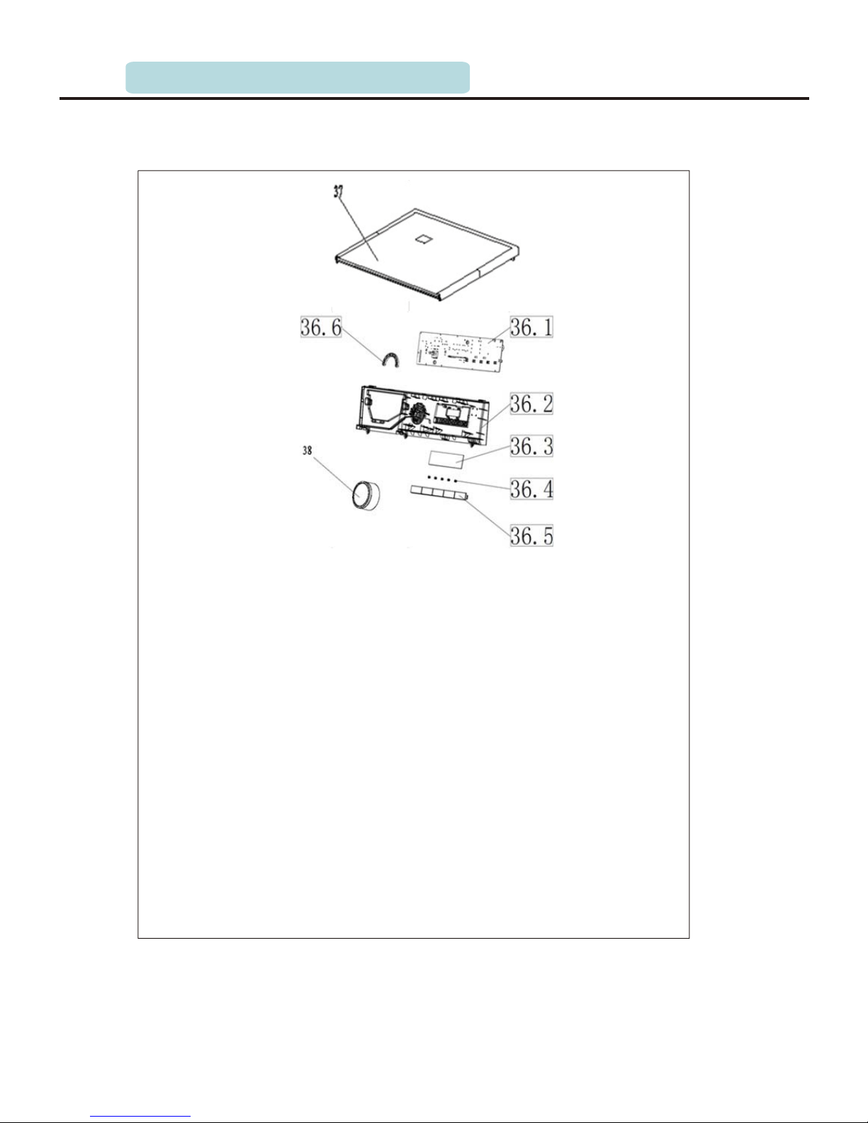
36 Control Panel Sub
36.3 dalle
36.2 Control_Panel
36.1 PCB
36.4 Start_pause_spring
36.5 Button
36.6 Light_Transferrer
37 Top_Cover_Board
38 Cycle_Select_Knob
2.INTRODUCTION OF PRODUCTS
Page 11
P. 11
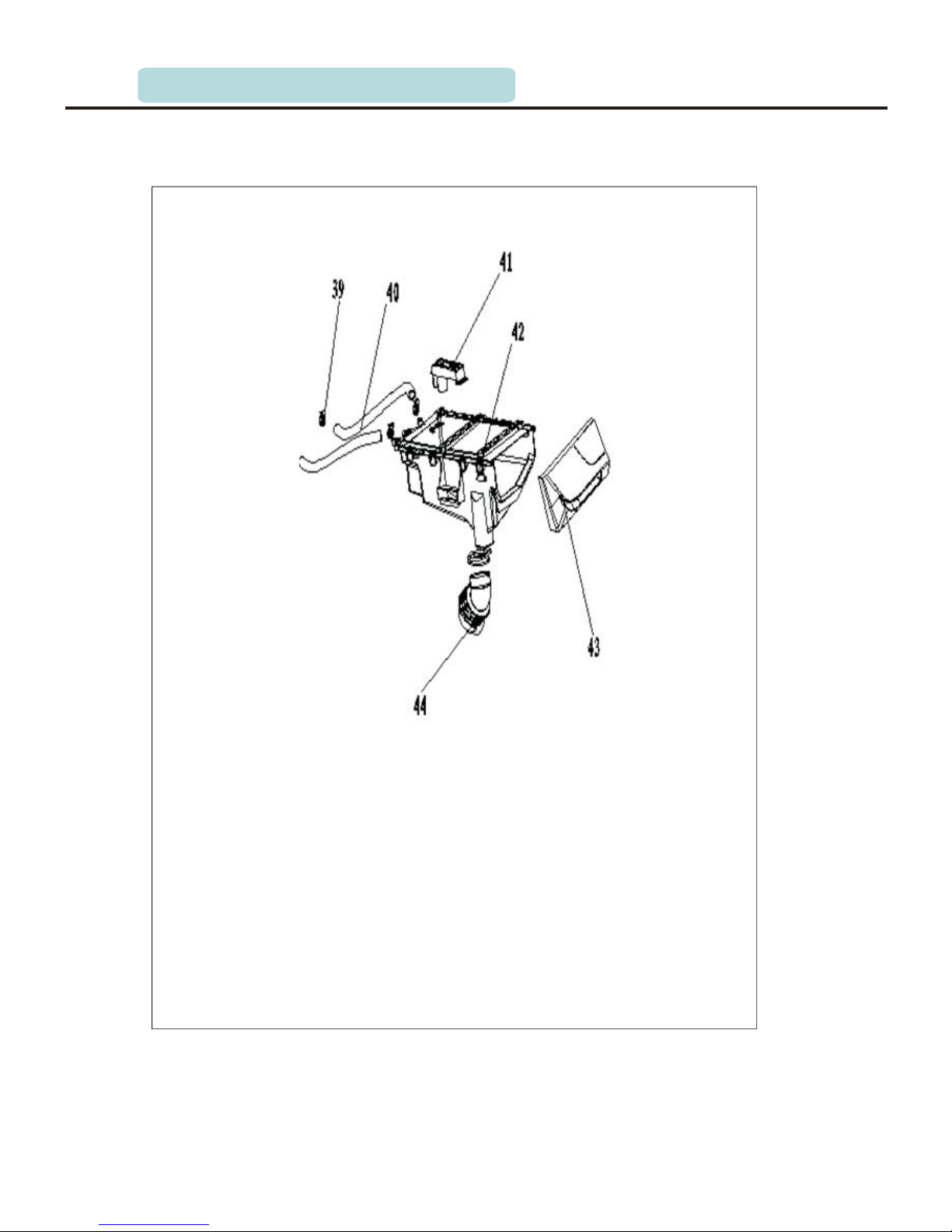
2.4 Explored & list of partsview
39 Hose Clamp
40 Inleft Hose
41 Softener Cap
42 Detergent Box
43 Drawer Panel
44 Tub Water Inlet Hose
2.INTRODUCTION OF PRODUCTS
Page 12
P.12
2.Overview of products
2.4 Explored & list of partsview
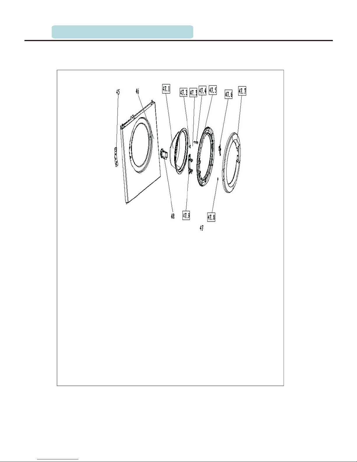
45 Door Support Plate
46 Front Panel
47 Door Sub
47.1 Door Glass
47.2 Door_Plunger_Spring
47.3 Hook Pin
47.4 Door Plunger
47.5 Inner Ring
47.6 Door Handle
47.7 Outer_Frame
47.8 Door_Hinge_Pin_Cover
47.9
Door Hinge
48 Door Lock
2.INTRODUCTION OF PRODUCTS
Page 13
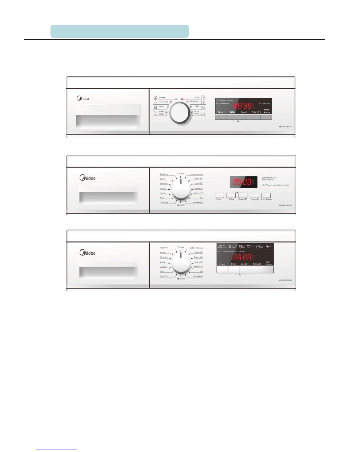
2.5 Introduction of control panel
G02
P.13
G01
1.Drawer Panel: put detergent into detergent box by pulling out Drawer.
2.Control Panel: manipulate washing machine with the panel.
3.Knob: revolve this knob and select washing program accordingly ( cotton, synthetic,
wool) can be selected circularly.
4.Function Button: achieve functions of speed selection, temperature selection etc.
5.Start/Pause Button: press this button to restart or pause will be done.
6. Display screen: show washing process and relative error information.
2.INTRODUCTION OF PRODUCTS
G03
Page 14

P00
P01
P02
P03 Cotton 40°
P04 Cotton 20°
P05 Quick 15'
P06
P07
My Cycle
Cotton Intensive
Cotton 60°
ECO Wash
Rinse & Spin
Programs corresponding with the encoder knob
P.14
2.6 of basic Function
2.INTRODUCTION OF PRODUCTS
P08
P09
P10
P11 Delicate
P12 Mixed
P13 Synthetic
P14
P15
Spin Only
Drain Only
Wool
Sports
Baby Care
- Cotton
You can select this procedure to wash the daily washable clothes. The washing period is quite long
with quite strong washing intensions. It is recommended to wash the daily cotton articles, for
example: bed sheets, quilt covers, pillowcases, gowns, underwear etc.
′
- Synthetic
You can select this procedure to wash the quite delicate clothes. The procedure is shorter
compared with that for cottons and the washing intension is quite gentle. It is recommended to
wash synthetic articles, for example: shirts, coats, blending. As for curtains and laced textiles,
the procedure “Synthetic ” shall be selected. While washing the knitting textiles, detergent
quantity shall be reduced due to its loose string construction and easily forming bubbles.
- Wool
You can select this procedure to wash the wool textiles labeled with “Machine Wash”. Please select
the proper washing temperature according to the label on the articles to be washed. Furthermore, the
proper detergent shall be selected for wool textiles.
- Cotton Intensive
To increase the washing effects, main additional washing time is increased.
It is recommended to wash the clothes for babies or worn by the persons with allergic skin.
- Quick 15
This procedure is suitable for washing few and not very dirty clothes quickly.
- Eco Wash
As for few light dirty clothes, the maximum temperature of washing is limited to 40℃ , and saving
more energy.
- Baby care
Baby care procedure with an extra rinse, it can make the baby's wear cleaner and make the rinse
performance better to protect the baby skin.
- Sports
You can select this procedure to wash the activewear.
- Mixed
You can select this procedure wash the tough cltohes, that need much more time and strength .It is
used for the daily clothes fo cotton,such as sheets, chained, pillowcases bathrobe and underwear.
- Delicate
You can select this procedure to wash your delicate clothes. Its washing intension is gentler and
revolution speed is less compared with the procedure “Synthetic”. It is recommended for the articles
to be washed softly.
Page 15

P.15
2.7 Function of safety guard
2.7.1 Function of avoid overflow
When the water level is up to the abnormal height in the drum(the set warning level),
washing machines will automatically switch on drainage pump to drain by pressure
switch, even if the inlet valve failure which can not stop the inflowing water, the
washing machine will not be in the overflow. At the same time, the pressure switch will
feed back to control panel a signal of fault and the washing machine will alarm.
2.7.2 Function of avoid heating without water
When there is no water or not enough to submerge the heater, and at the same this
machine is in fault, the fuse in the heater will melt to cut off the heater and avoid danger.
2.7.3 Function of bubble checking
About wiping off bubble: When the water level is lower than level I during draining, the
2.INTRODUCTION OF PRODUCTS
spin function will start. If there is over much bubble in the drum, it will increase the
pressure in the drum and switch on the pressure switch , at the same time the PCB panel
begin the bubble checking function and clean it away.
Page 16

P.16
2.7.4 Function of auto-balance
1. This function will start before spin and after drainage.
2. Drum reverses the speed of 50 rounds per minute in the first six seconds.
3. In the next 10 seconds, the rotational speed from 50r/m to 100r/m slowly.
4. In the following 18 seconds, the washing machine rotates in the speed of 100r/m and
estimates the degree of imbalance according to the signal of the motor.
5. If the degree of imbalance is more than the setting value, the auto-balance system will
feed back imbalance information of 12 cycles.
2.7.5 Function of child lock
To avoid the fault operation by children and then making this wash procedure work
abnormally, you can select this function in which other buttons can't be work except knob.
As for this machine, press the second button and the first button at the same time for 2.5
seconds from left , the buzzer rings and the pre-wash button, auxiliary function button,
start/stop and knob are locked. And then, press them at the same time for another 2.5
seconds, the buzzer rings again and the locked buttons are unlocked. Child lock function
is cancled after the whole program is completed when child lock is effective, press the
non-child lock button and then buzzer rings to remind that operation is invalid.
2.7.6 Program memory
If the running washing machine is powered off, its washing procedure will be stored in
chips. When the power is on, washing machine will run from the memorying procedure.
If washing machine is powered off during spin, the machine will spin from the start of the
procedure again.
2.7.7 Function of motor self-protection
When the washing machine works in the poor conditions, the enormous load on the motor
will make its temperature increase and its performance decrease even burned motor.
When its temperature increases to a set value, the thermal protector of motor will
automatically cut off the power supply to achieve self-protection and alarm.
2.INTRODUCTION OF PRODUCTS
Page 17
P.17
3.1 Select the location
1. Washing machine must be placed in the formation, firm, dry and well-ventilated places.
2. Washing machine need a certain space and the shortest distance from the wall is not
less than 12cm generally.
3. Don't place the washing machine in the condition of freeze-easy.
4. Washing machine should be placed away from heat, sunlight to prevent pieces of
plastic and rubber become aging.
5. Do not put the washing machine in the place where it can be exposed to rain and snow.
6. It is not suitable to use the washing machine on vessels, aeroplanes and vehicles.
7. To avoid walling up the vent, please don't put washing machine on the carpet.
NOTE: Washing machine should be put in the room which have enough space, such as its
door can be fully opened.
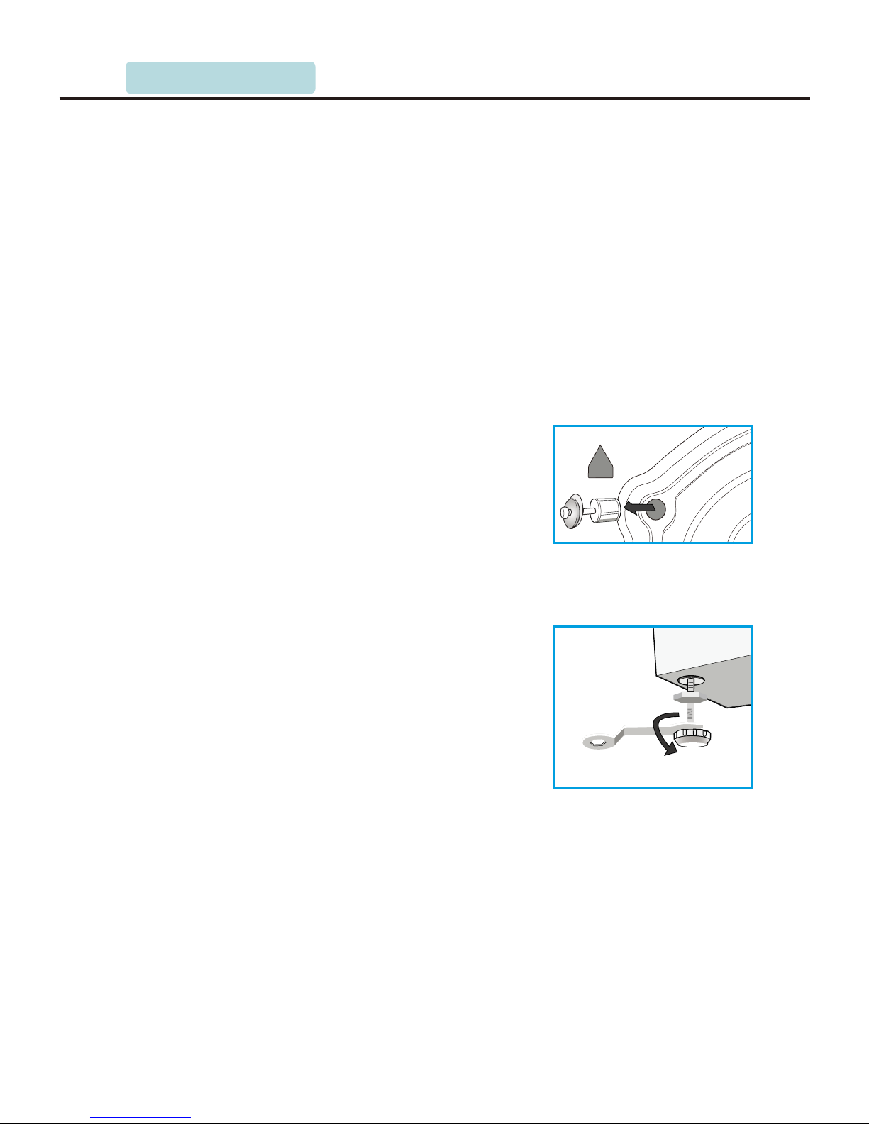
3.2 Remove transport bolts
Before using this washing machine, transport
bolts must be removed from the backside of
this machine.
Please take the following steps to remove the bolts:
1. Loosen all bolts with spanner and then
remove bolts.
2. Stop the holes with transport holes plugs.
3. Keep the transports bolts properly for future
use.
3.3 Adjust leg
1. When positioning the washing machine,
please first check whether the leg are closely
attached to the cabinet. If not, please turn them
to the original position with hand or spanner
and tighten them with spanner.
2. After position washing machine, press four
corners on top cover of this machine in
sequence. If the machine is not stable, this
leg should be adjusted.
3. To ensure the positioning status of washing machine, loosen the lock nut with spanner
and turn the leg with hand until it closely attaches to floor. Press the leg with one hand
and fasten the nut closely to the cabinet with the other hand.
4. After being locked properly, press four corners again to make sure that they have been
adjusted properly. If it is still unstable, above-mentioned steps shall be repeated by 2
to 3.
NOTE: In principle, there is only one loosen leg at most. If this leg is located at back of
this machine and it is inconvenient for adjustment, then another leg at its diagonal position
can be adjusted to achieve the same effect.
3.INSTALLATION
Page 18
100cm
140cm
Min60cm
Max100cm
110cm
P.18
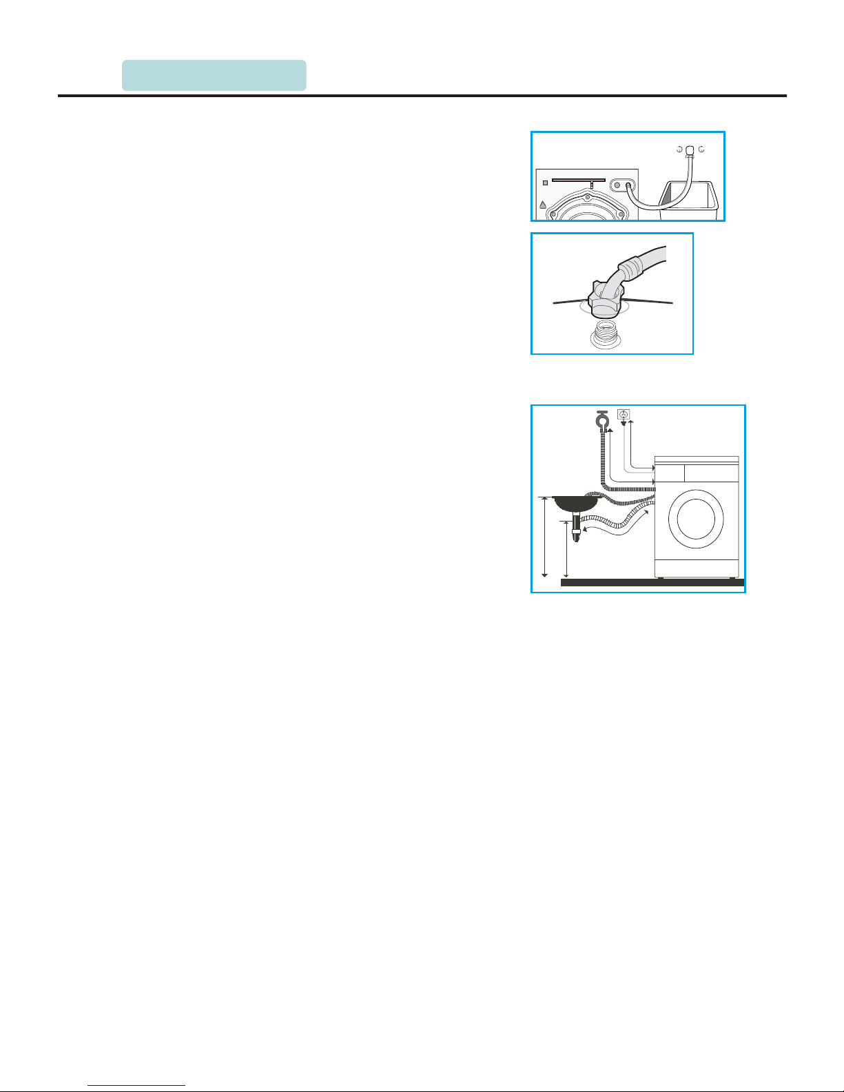
1.Connect the elbow to tap and fasten itclockwise.
2.Connect the other end of inlet pipe to the inlet
valve at the backside of washing machine and
fasten the pipe tightly clockwise.
NOTE: after connection, if there is any leakage with
hose, then repeat the steps to connect inlet pipe. The
most common type of tap shall be used to supply
water. If tap is square or too big, then standard tap
shall be changed.
3.4 Connect inlet pipe
Connect the inlet pipe as indicated in the figure.
3.5 Place outlet hose
There are two ways to place the end of outlet hose:
1. Put it beside the water trough.
1) Washing machine shall be located nearby the
slipway’s inlet so that it is convenient for this
machine to drain.
2) Take out splint from PE bag and fasten it on the
end of the drain hose, and then put it beside the
water through or the slipway’s inlet.
NOTE: clean up the filter of outlet valve, don’t fold it,
don’t clog the inlet/outlet hose to make sure them
expedite to inlet or drain.
2. Connect it to the branch drain pipe of the though.
3.6 Electrical connection
1. The maximum current through the unit is 10A when this machine heats the washing
liquid, and please make sure that your household power supply system (current, power
voltage and wire) can meet the normal loading requirements of the electrical appliances.
2. Please connect the power to a socket which is correctly installed and properly earthed.
3. Please make sure your household power voltage is same as that of the machine’s rating
label.
4. Power plug must match the socket and cabinet must be properly and effectively earthed.
5. Do not use multi-purpose plug or socket as extension cord.
6. Do not connect and pull out plug with wet hand.
7. When connect and pull out plug, hold the plug tightly and then pull it out. Do not pull
power cord forcibly.
8. If power cord is damaged or has any sign of being broken, special power cord must be
gotten from its manufacturer or service center for replacement.
9. Has been positioned, the plug of Washing machine should get to socket properly and
effectively.
3.INSTALLATION
Page 19

P.19
3.7 Installing and checking items
1. Check whether remove transport bolts or not.
2. Check whether the socket is installed and properly earthed.
3. Check whether this machine is level or not.
4. Check whether inlet pipe/outlet pipe is wringed or not .
5. Guide user to operate the washing machine and make sure no leakage and no abnormal
sound.
NOTE: please read instruction manual carefully to ensure the proper operation of this
washing machine.
3.INSTALLATION
Page 20
4.OVERVIEW OF MAIN COMPONENTS
P.20
4.1 Top cover kit
1. Parts component
Top cover is made up of hyperbaric plate, top
cover-f and top cover-b. Both top cover-f and
top cover-b are ABS materials. Front of top
cover lock to the panel support of this machine's
cabinet, and back of top cover fastnesses to the
U-type backside of cabinet with screw.
Two-piece of hyperbaric plate is covered by
melamine which is waterproof and fireproofing,
and furthermore, the dirt and smudge on its
surface could be erasured easily.
2. Summery about function
The two screws fixing the top cover screw into the
cabinet to avoid loosening.
Chang and maintain PCB kit, pressure sensor,
filter, inlet valve after unpack top cover kit.
4.2 Drawer panel kit
1. Drawer, Drawer panel and Softener cap
Drawer panel kit is consist of drawer, drawer panel and softener cap. Drawer panel is
clipped on the face of draw without screw and softener cap in the center of drawer.
According to the need of costumers, different detergent could be placed in three boxes
of drawer respectively, and concretely the right one is pre-wash box, the left one is main
wash box and the center one is softener box. Certainly user can put decolourant, spicery
and softener in the center one to improve washing performance.
After water fill in the drum through drawer, siphon structure of inlet system ensure that
drawer have no remanent water or wash liquid.
Drawer can be taken out and cleaned up: Unfold the drawer up to 10cm, and then take
out the drawer at the same time press the elastic plate to avoid injuring the softener box.
What is noticeable: during cut the softener cap in the detergent box, you have to press
the protuberant support of its end.
During the washing machine’s in work, it should remind user of closing the drawer, or
else, the detergent can’t be flowed into the drum completely, and what is worse water
may flow out from the outside of the cabinet.
2. Draw panel deck
The material of drawer panel kit is PMMA.
Page 21

P.21
4.Overview of main parts
4.3 Control panel kit
Control panel kit consists of control panel, dalle,spring, button,light transferrer etc.
As the key apparance part of washing machine, control panel's appearance and quality
have direct influence on costumers. Midea washing machine is known as fashionable and
compact appearance.
The material of control panel is the slap-up and splendid ABS material and its mold is
specular polished.
4.4 Front plate
The material of front plate is PCM and its thickness
is 0.8mm. Connection of Front plate and cabinet is
pensile structure with screw. Both sides of the back
of the front plate have a hole respectively which is
to append front plate support. Finally maintainer
can fasten front plate on cabinet with five screws.
Three holes at the top of the front plate is used to fix
the control panel.
Door hole is in the center of front plate, and its left
side is hinge and the right side is door lock.
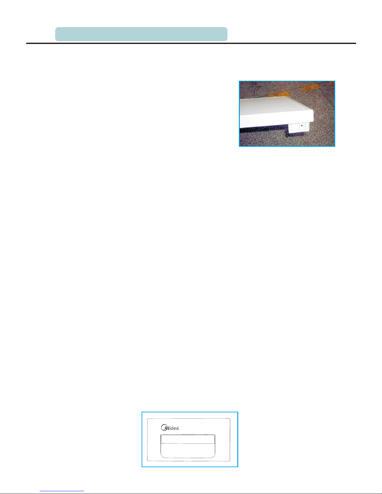
4.5 Lower panel
Lower panel is locked to lower
reinforce and then fixed with a
screw.
4.OVERVIEW OF MAIN COMPONENTS
Page 22
P.22
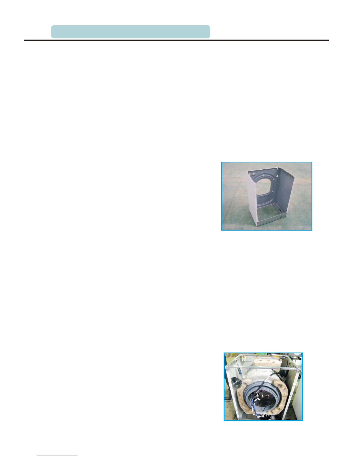
4.6 Cabinet kit
The material of the cabinet is PCM colorful metal,
and cabinet fold and reinforce are fixed by TOX
riveting technique, the panel support is fixed with
cabinet with screws.
Fixed in the top of the cabinet through TOX riveting
technique, left and right-up reinforce reserve spring
hole, pressure switch assembly hole, cable channel
hole and screw hole of the PCB board support.
Left and right-down reinforce on top of which it is
special fold design of fixing absorber is fixed down
of the cabinet through riveting techque.
Down reinforce is riveted down of the cabinet front
cover, on top of which the lower panel fixing hole is
reserved. The bigger hole is used to fix the pump,
down of which is two screw hole used to fasten the
lower panel.
The left and right hole on the up-front of the cabinet
is panel support hole.
There are inlet valve fixing hole, cable holder-s
hole, outlet hose hole, and power cord hole from
left to right on the up-back of the cabinet.
In the convenience of maintenance, there is a
bigger rear panel hole in the middle of the cabinet.
When fixing the rear panel, you should insert the
upper part into the hole, then fix two screws in the
bottom.
The three holes around the rear panel are transmit
bolt holes.
Furthermore there are three outlet hose fixing
support holes on the upper and left of the rear
cabinet to fix the outlet hose and power cord.
And there is two-leg power plug on the left of the
bottom.
4.7 Panel support
As the metal slat, Panel support is used to increase
the intensity of cabinet and fixed on the control panel.
Panel support is fastened on the cabinet with two
screws locating its both sides.
4.OVERVIEW OF MAIN COMPONENTS
Page 23
P.23
4.Overview of main parts
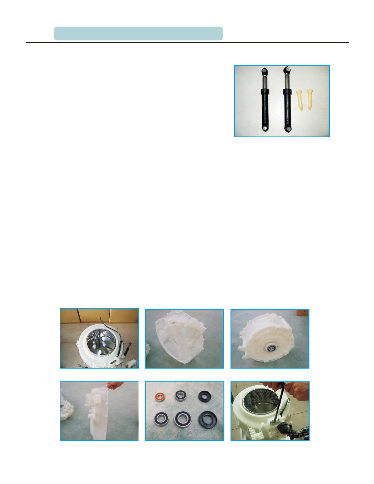
4.8 Absorber
Midea drum washing machine uses the advanced
absorber to damp the vibration by drum tub kit
when this machine wash and spin. Absorber uses
friction damping to achieve its function of damping
vibration. Thanks to its similar the piston-type
structure, the sponge in the cylindrical plastic inner
wall of cylinder and the cavernous metal rod
contacts close, the cylinder rod can sliding along
the axial and longitudinal, which generate a certain
damping force. There is special cavernous damping
oil in the sponge, which is the main part to achieve shock absorber. The damping force
keeps constant and its direction is opposite toroid running. Absorber pin is used to
connect left/right lower reinforce to absorber, the absorber and tub as well.
4.9 Drum tub assembly
4.9.1 Rear tub kit
As a container for water, the tub capability of this washing machine is not only effects
it's rated washing capacity but also decides its rated consumption of water. That is, at the
same condition of water level, the radial dimension and the lengthways dimension of its
tub have larger, the more its rated consumption of water.
The tub material of Midea washing machine is well property and improved PP which is
high intensity, heat-resistant and high rigid. As a good heat guard, PP ensures this
machine save power and improves its washing performance in a sense.
This structure, which is divide tub kit into front tub kit and rear tub kit, improves the
assembly performance of this machine and enhance its airproof.
4.OVERVIEW OF MAIN COMPONENTS
Page 24
P.24
4.Overview of main parts
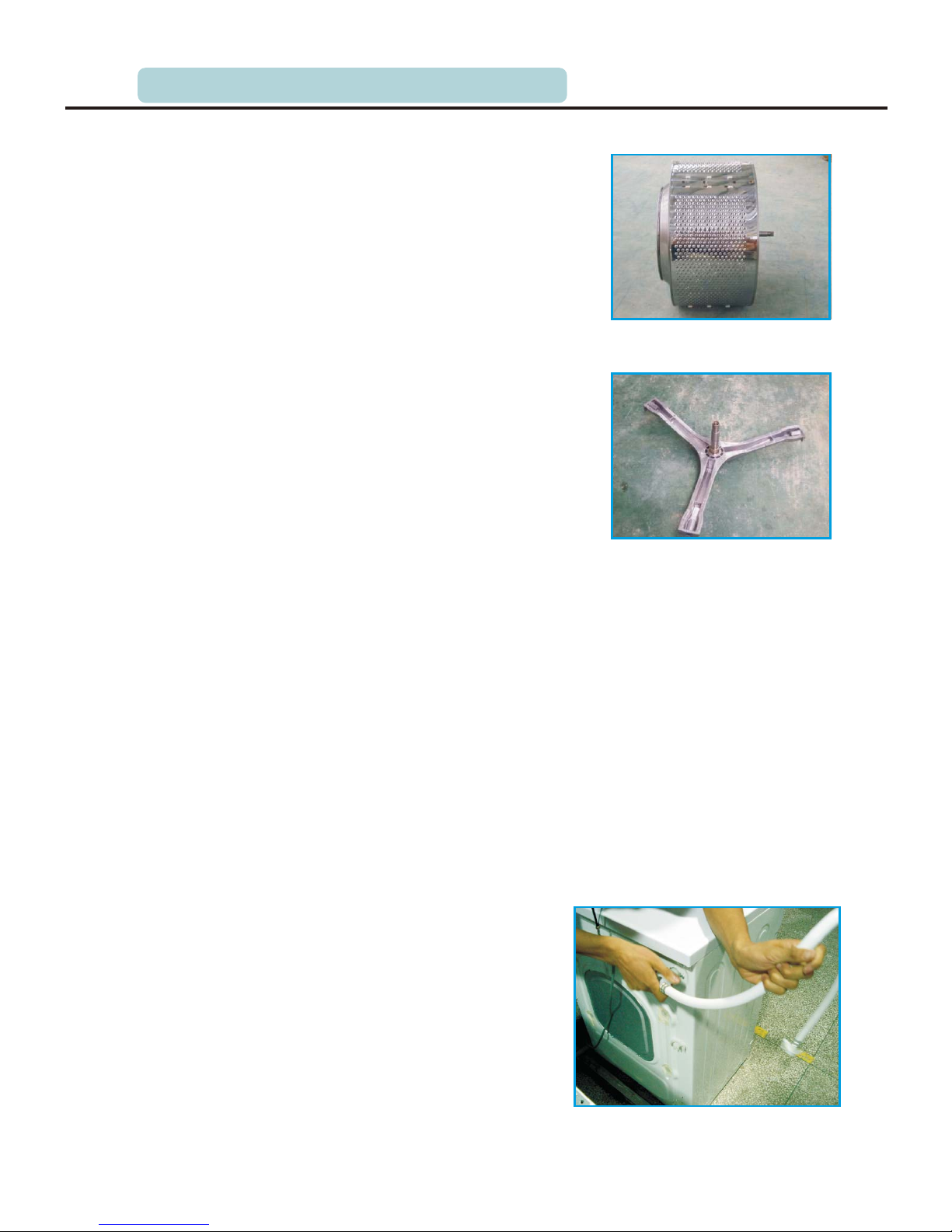
4.9.2 Drum kit
Drum kit consist of drum center, drum front, drum
back, lifter, spider kit (spider, shaft, shaft bush),
and spider bolt etc.
The structure and characteristic of drum:
Drum is made up of drum center using stainless
steel, drum front, drum back. As the class BA of
AISI 430 BA stainless steel, it is blighting.
After rolling the inside of drum front, the sharp
cutting edge rolled up to prevent scratching textiles
and arm during removing and adding textile.
The model shape repression of the meet between
drum back and spider enlarge the space putting
textile. The piercing and drawing reel ensure the
textile no injury during washing and spinning, and
the compact holes make sure the textile soak fully
in the drum.
Drum and drum front/back are connected by
advanced spinning curling process.
During the washing, three lifters hold up the clothes pressing against the affixed surface
of the drum. When clothes raised close to the top, centrifugal force is not enough to
overcome gravity, and therefore clothes fall and impinge washing liquid to improve
washing performance.
Spider kit
The spider is the aluminum die-casting. There is a bushing in the axis which is to reduce
the wear and tear of V-shaped edge of the oil seal. When installed bushings, the
powder-like debris produced by it cut shaft bushings should be removed, or they will
wear oil seal. To avoid wear and tear, grease should be applied the corresponding
position of the oil seal to ensure that it will play in the role of lubrication in the whole
life of washing machine and not dry or off. Spider kit is fastened on the drum with three
stainless steel bolts.
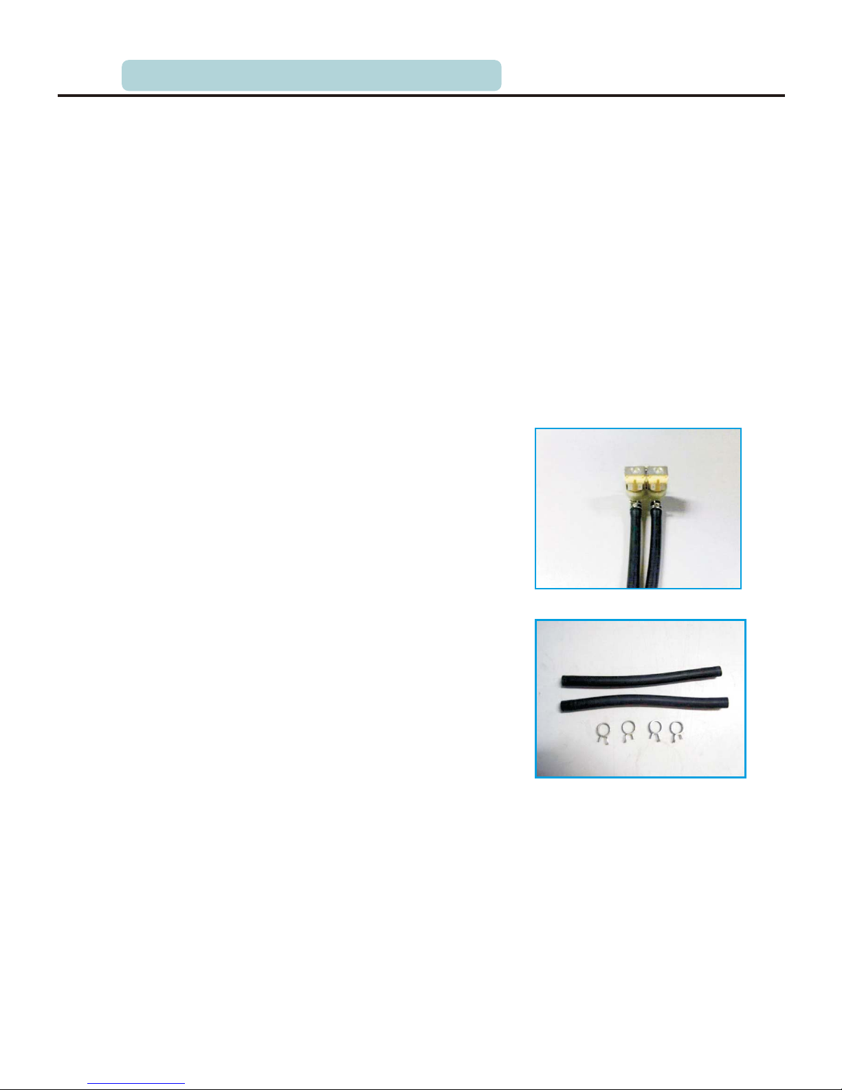
4.10 Inlet hose
Inlet hose connects household tap and washing
machine. The pipe of inlet hose has a high-pressure
capacity which nets the high strength polyester
fiber lines. Generally, household water pressure is
less than 1MPa, and practically the water pipes of
Midea washing machine could stand the pressure
of 2MPa in one minute not dehiscence, not
deformation, and bearing 4MPa pressure not burst.
As for inlet hose, there are many performance
requirements such as hot and cold alternate anti-shocking, anti-bending etc.
4.OVERVIEW OF MAIN COMPONENTS
Page 25
P.25
4.11 Inlet system
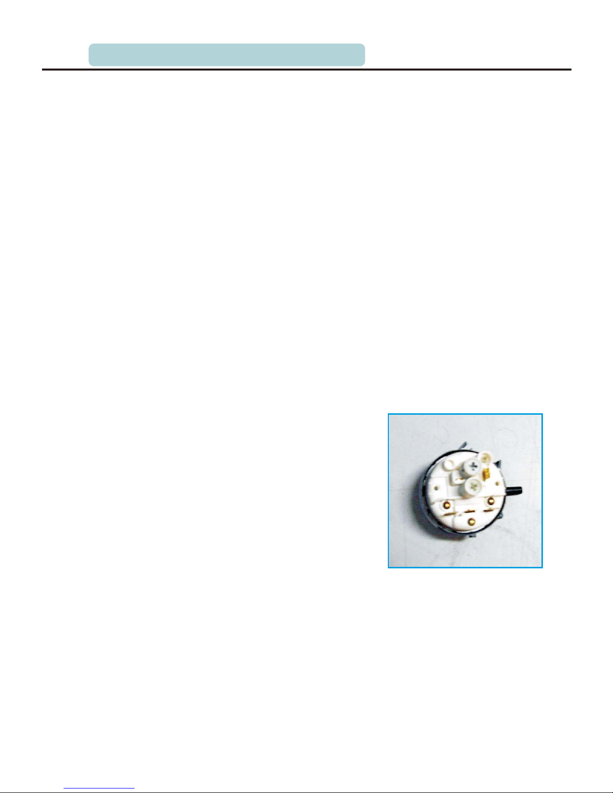
4.11.1 Pressure switch
Working principle
Mechanical pressure switch have two main components that is balloon and electrical
structure. The balloon is fastened sealedly on the pressure switch with hose clamp and
the end of balloon is connected on the bottom of tub using press chamber, plastic pipe.
During flowing water, the bottom of tub is firstly submerged and its space linking the
balloon is closed. With the increase of water level and the pressure of closed air increase
gradually until push the needle of rubber membrane.
Another parts is the electrical structure. With the balloon inflating, a needle top spring
chip to make it conduction and then change the current direction.
Usually, the fault of pressure switch is leakage and contact barrier. It is easy to check
them.
Huff the inlet inflatable with your mouth, and you can clearly hear the clatter sound of
spring chip clicks, if it is multi-level control, several clatters sound can be heard.
There is a group of plastic crosser screw in the side nearly line. These screws are used to
control the height of water level (to avoid adjust it, there is a certain color lacquer to
sign).
Pressure switch is a very important part in the washing machine, which is not only
control water level but also influence the safety of washing machine. Once it is invalid,
water level can’’t be controlled.
Low-frequency analog electronic pressure switch:
its main principle is a group of LC oscillation
circuit, the change of balloon changes the frequency
of LC circuit. Pressure switch feedback to the PCB
signal, and PCB issued in accordance with the
conditions set to decide water level.
The price of low-frequency analog electronic
pressure switch is high and as a result its application
rares.
In a word, pressure switch employs its closed gas
room as the basic condition of normal work. And if
the gas room is damaged, the pressure switch will
be invalid.
In addition, pressure switch is the key part
controlling heating circuit.
4.OVERVIEW OF MAIN COMPONENTS
Page 26
P.26
4.11.2 Inlet valve
Working principle of inlet valve
Inlet valve has two main components: One is the 220V winding which Set in the injection
molding nylon colophony Pa66 outside cylindrical cavity and there is an iron core inside
of cavity. And normally, iron core is not in the center of cavity due to the spring force.
Once power supplys, the magnetic field produced by winding generate force overcoming
the spring force to drive iron core, which open the hole of releasing pressure in the inlet
valve.
The other is the channel part. There is a hole between inlet and outlet that control flux.
The default of the hole is closed and controlled by the hole of releasing pressure in the
inlet valve.
As a result, the fluxing hole can be opened on the condition of power supply, iron core
moving and the hole of releasing pressure.
In a word, inlet valve works in the condition of power supply and water pressure.
Characteristics of inlet valve:
1.Flux: the flux of inlet valve is different by
different manufacturer produced. And the flux
value usual is from 8L/min to 12L/min (the flux
value of this machine is 9.5L/min).
2. Modality: the inlet valve is common single-head
valve for the atmosphere can be programmed for
mechanical models, the direction of water flow
when a cam driven by program - controlled link,
Plectrum agencies to achieve watershed; The
second category is double-head valve, which is
used in electronic-type program - controlled
washing machine, and usually water influent from
the “pre-wash”box, and the other washing box is
the main box, and when the two valve boxes at the
same time electricity, water influent from the rinse
box, its on / off is control by PCB panel.
The last category is three-head valve, which is used
in electronic device programmed with the function
of drying washing machine, two of grids have the
same functions as well followed. And the third one
is used to control condensed water, which has
small flow.
3.Resistance: the resistance of single-head valve is
about 4000Ω。
4.Power value: the power value of single-head
valve is about 5W.
4.OVERVIEW OF MAIN COMPONENTS
Page 27

P.27
4.11.3 Detergent box kit
Detergent box kit is made up of detergent box,
Detergent box-up and Detergent box-middle.
At first, Detergent box-up and Detergent box-middle
are pieces of plastic absolute. They are connected
and produce many flume as the channel of water
flow to weep away the detergent in the box. In order
to achieve European standards, an overflow mouth
is designed in the detergent box to prevent washing
water inflowing the family water system caused
pollution.
4.11 Drain system
4.12.1 Drainage system
The material of drain hose is Ethylene-Propylene Diene Monomer (EPDM), whose rigidity is 50sha,
default thickness is 2.5mm. The drain hose has
anti-loosen structure and it ensure there is no
leakage during work.
4.OVERVIEW OF MAIN COMPONENTS
Page 28

P.28
4.12.2 Drain pump
As for the up-drainage washing machine, the drum
washing machine need drain pump to provide the
force. The drain pump head is generally 1~1.5m,
tonnage is 24L/min.
Drain pump is made up of motor, body, impeller,
blower fans. Impeller is derived by the motor to
run and drain; the blower fans disperse the heat
produced by motor.
In principle, the drain pump has two categories
of permanent-magnet pump and cover pole pump.
And drum washing machine usually use the permanent-magnet pump now.
The permanent-magnet pump uses the permanent-magnet motor and its winding
resistance DC is about 170Ω. And its resistance usually can be measured by
millimeters. If resistance infinite, it can be concluded its opening.
Actually, the common faults of drain pump was mainly that impeller broken flannel or a
hard object jammed or the hard object interrupted by the impeller, and this will cause
drain pump can not work. the drainage pump will issued swoosh at the end of draining
due to the some water can not be completely discharged from the machine, it is a normal
phenomenon.
Due to the internal structure of a cavity, filter components upper and lower body by
ultrasonic welding.
The filter kit main role is Filtering out clastic produced by washing. If don’t clean it
timely, it will cause many fault such as pipe plug, Drainage difficulties.
Filters should be washed once a month generally. Remove it before draining water and
then put a basin to avoid the remaining water flowing on the
floor. Mold cleaning filters carved steps and attention to the
matter in the back of the trap door. During installing it again,
the filter should be tightened, otherwise easy leakage.
4.13 Door kit
Door kit is made up of outer door, inner door, door glass, door
handle, door hook, door hook spring, hook pin, hinge, hinge
cap and screw.
The material of outer door is Acrylonitrile Butadiene Styrene
(ABS) which have the good anti-aging and anti- ultraviolet
properties, and it is elegant generous.
The material of inner door is the improved PP material.
Door glass is not only good high temperature and impact
resistance properties of hot and cold, but also a high intensity.
Door handle is embedded or external.
When open the door without loosening after assembled door
handle, door hook, door hook spring, hook pin.
4.OVERVIEW OF MAIN COMPONENTS
Page 29
P.29
The material of door hook is zinc alloy. As well hinge, the material of the hinge cap is
POM, and the cap set in the pins of hinge ends.
The door lock control the door after installing it correctly, the clasp of door lock enter
the mouth of the plate front and then they are fixed with screw to avoid scratch between
the door hook and the cabinet. After power supply, door hook will be locked and the door
can’t be opened.
4.14 Gasket
Gasket is injected molding with EPDM which has
many properties such as the high temperature,
corrosion resistance, anti-aging.
The gasket of Midea washing machine has
processed using advanced technique and it has
very well performance and beautiful color. What
is more, gasket achieves the goal of flexible
connectivity between cabinet and tub.
4.15 Door lock
Door lock is the device that is self- locking during
electricity and feedback signal to the PCB panel.
Delay function: the door can be opened after the
unit is off in two minutes.
4.16 NTC temperature sensor
NTC can detect the temperature range from -5℃
to 103℃. The heating function stops in the
condition of fault (open or short circuit).
Change the NTC before loose the crimpling
device.
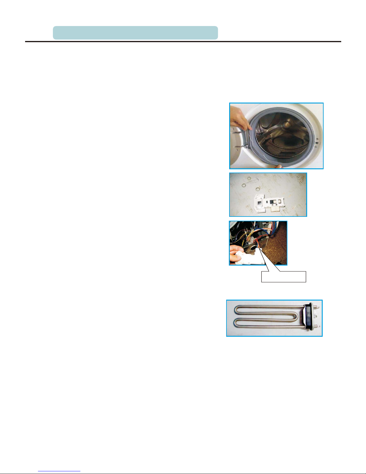
4.17 Heater
The body of heater is the heating pipe of stainless steel, and its insulation is magnesium
oxide powder and the core is the heating filament. The airproof of heater is EPDM which
has many properties such as the high temperature, corrosion resistance, anti-aging.
The stainless steel heating pipe is welded using sub-arc welding and Seamless Detection.
And then intercept set length to install the heating filament and fill magnesium oxide
powder, and then tamped through vibration. Finally, a diameter of 12mm heating pipe
compressed into 8mm with horizontal compression technology, and that is strictly ensure
the full magnesium oxide powder tamped and the quality of welds.The heater is fastened
on the tub with bolt.
Electrical principle:
Heater uses power of 220V voltage and 50Hz frequency. Due to the rated current is less
than 10A, the most power of washing machine is less than 2200 watts. Reducing the other
Harness plug
4.OVERVIEW OF MAIN COMPONENTS
Page 30

P.30
power, the most power of heating at 90℃ is in the range from 1800 watts to 2000 watts
and 1000 watts at 60℃.
The heater can't heat without water, so firstly the heating function will start only user
selects the heating procedure, and secondly heating function is in some special procedure
to avoid unreasonable heating, and thirdly when water level is up to the set level, its
function will operate. In addition, there is the melting device in the heater, and when the
temperature is up to set value(usual setting 160℃), Fuse is fused and cut off power supply.
4.18 Filter
The power change of drum washing machine is in
the scope and larger, and in order to prevent its
interference on the other household appliance and
interfered by the other large appliance, the filter is
installed in the washing machine by CCC
certification requirements.
Filter is made up of a group of capacitance (usually
three), a group of inductance and a resistor. In the
power supply circuit, it can inhale the high-order
harmonic from washing machine and earth.
The interference is from the high-order harmonic from the power changes of washing
machine as well as the disorders and alternating magnetic field according to the
continuous changes of the current in the power cord. The frequency and magnitude of
change of its power is in the scope and larger that is from zero watts at soak to hundreds
of watts at wash, rinse and spin, to nearly 2000 watts at wash with heating. This change
more easily aroused the obvious voltage fluctuations in the domestic circuit which effects
the normal use of other electrical appliance. These filters can filter out high-order
harmonic and earth.
EMC stressed interference and anti-interference, and as for washing machine, it is
important to reduce interference to others due to it has good anti-interference.The
washing machine use alternating current that can pass capacitor, and in practically, filter
will have a very small leakage current (generally less than 2mA). Good grounding is the
guarantee of the safe using this machine.
And as a result, we particularly stress the importance of grounding. Sometimes, there is
an anesthesia in the working machine, please check their grounding device firstly.
4.OVERVIEW OF MAIN COMPONENTS
Page 31
P.31
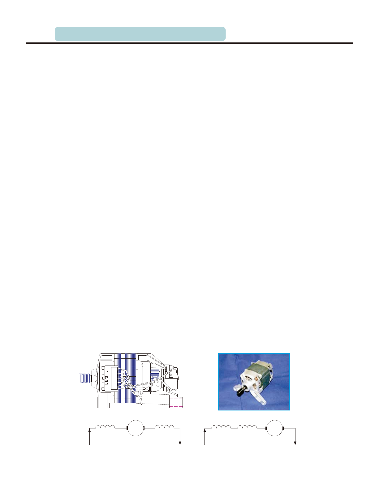
4.19 Motor
1. Summary of motor
As the driving components, motor drive the drum during washing and spin. Currently,
the motor of drum washing machine usually have two-speed motor and series motor.
1) two-speed motor is the running capacitance of single-phase AC asynchronous motor.
Stator of the three-phase AC motor embedded in the three-phase windings 120°. If it
has symmetrical in the three-phase windings, it can produce rotating magnetic field.
Due to using single-phase power, the stator windings of washing machine in the
single-phase AC electromagnetic field generate field is a pulsating magnetic field.
And this pulsating magnetic field can be divided into two a rotating magnetic field, and
their speed equal to the opposite direction. And therefore, their synthetic torque is zero
and motor can't be activated except issuing electromagnetic buzzing sound.
To start motor, washing machine motor normally uses two measures: First, put
embedded in the trough of stator two windings, the main windings (running winding)
and the vice winding (start winding), and two windings around axes in space in a 90°
angle. Secondly, put a capacitor in series on the winding and therefore the same
currents have different phase difference on the two winding. As a result, the vice
windings has leading 90° current to the main windings , and make the condition of
starting motor.
The space between stator and rotor is air gap. Motor has two ways of cooling, natural
cooling and fan cooling (air-cool or self-fan cool).
2). Series motor
General speaking, series motor is a DC motor. Its highest speed can be up to 20000r/min.
Performance characteristic: Its electrical characteristic is hard, the size of it output
torque is not effect on the change of voltage. Its has large range of regulating speed and
has relatively high efficiency which value is up to 0.2 at the speed of 700r/min and 0.63
at the spinning.
Work principle:
There are two series ways between exciter stator windings and the armature windings.
The one is that the armature windings series two exciter windings in the figure A; and
the other one is that two exciter windings series before they series the armature windings
in the figure B. And practically, the first way is used more.
ExciterExciter
i i
Armature
Exciter Exciter
Armature
Figure A:armature wires series-wound
between two exciter wires
Figure B:armature wires series-wound
with two exciter wires
4.OVERVIEW OF MAIN COMPONENTS
Page 32

P.32
The structure of single-phase series motor decides it can use not only alternating current
but also DC. To predigest its circuit and reduce cost of this machine, it is usually to use
AC practically. Between the exciter windings and the armature windings are in series one
single-phase power supply. When it is in a positive and negative half-cycle AC, the
current passing the exciter windings and the armature windings are shown in the figure C
and D separately. In a word, the revolve direction of series motor which is used to AC
power supply has nothing to the power supply.
Change the shift of single-phase series motor before change the series polity of the exciter
windings and the armature windings, and show in the figure E.
Series motor usually changes voltage to adjust its rotate speed and the calculating
formula of its rotate speed is following:
(r/min)
E------inductive-voltage of the armature windings
a------the number of shunt-wound pairs of the armature windings
P------the number of magnetic polity
average flux of magnetic polity
N------the number of windings of armature windings
From the followed formula, if you change the structure parameter (P, N, a) of single-phase
series motor, and you can change its rotate speed. But as for the typed series motor, you
can change E and by adjusting the voltage value of the motor to change its rotate speed.
For drum washing machine, modulate the voltage using the electronic actiyator or the
PCB panel to adjust its rotate speed.
n=60aE/(PØN)
Ø------
n
+
-
ØØ
n
+
-
Ø
Ø
Figure C: rotor revolve direction in
a positive half-cycle AC
Figure D: rotor revolve direction in
a negative half-cycle AC
n
+
-
ØØ
SN
n
+ -
ØØ
NS
Figure E:rotating direction of motor after change the series polity of the
exciter windings and the armature windings
4.OVERVIEW OF MAIN COMPONENTS
Page 33

P.33
2. Main parts and structure of motor
Stator and rotor
Stator has rotating magnetic field, including stator windings, the core and upper/lower
cover for fixing it.
Stator windings is the high strength polyester enameled wire enwinding the core which
is sheeted with the silicon steel about 0.5mm thickness by riveting and welding. Both
sides of the silicon steel are coated with insulating paint, as well as rotor.
As the rotating parts, rotor output torque from its shaft, including the rotor windings,
core and axial. There is a belt pulley of the motor to output torque on the extended-rotor
shaft.
Gas gap
The unilateral width of the gas gap between stator core and rotor core usually is 0.3mm.
Due to the magnetic resistance of air is less than metal’s, gas cap is larger, the more is
magnetic resistance and the more is Exciting Current to produce the same size rotating
magnetic field, as a result, power factor of the motor become lower. To reduce the
exciting current, the gas gap should become small, taking into account safety factors of
assembly and transport.
Thermal protector
Usually use restorable double foils to cut off the power when the temperature of motor
more than the set one, to protect motor, the set temperature of foils is115±5℃, the
contractor will restart the power supply when the temperature is lower than the set one.
4.20 PCB panel
General characteristic
1)The control panel executes the main functions below:
2)Control the spinning(high-speed or low-speed spin
and the speed of the last spin)
3)Control the temperature of washing liquid
4)Control and adjust the unbalanced load during spin
The control of spinning speed
The control panel modulates motor’s speed by modulating
its voltage. By modulating the knob position of speed
chooser, the user can set the speed value in the control
panel. Then comparing the value of the speed and the
impulse value from testing motor, when the control panel
makes sure that the motor speed arrive the set speed, it will not modulate the voltage of
motor. As a result, the washing machine’s drum runs at the set speed.
The control of temperature of washing and heating
The user sets the temperature in the control panel by pressing the temperature key; the
control panel compares the set temperature and the washing temperature from the
4.OVERVIEW OF MAIN COMPONENTS
Page 34

P.34
temperature-testing resist value; when the control panel makes sure that the water
temperature arrives the set temperature, it cuts off the heater and stop heating.
The control of unbalanced load during spinning
When the washing machine is running the spinning program, if the clothes in the drum
are put unbalanced or gravely out of center, the washing machine will vibrate greatly, so
the control panel needs to adjust it. The detailed process is as below: when the washing
machine is running the spinning, the drum rotating speed will promote from low to high;
when it gets to 95r/min ,according to the principal that different eccentric clothes have
different rotating speed between ascending and descending, the control panel first checks
the testing motor’s rotating speed difference at 95rpm, after a special computing,
estimates whether the clothes in the drum balanced, such as balanced distribution. If
balanced, the washing machine will run at normal spinning speed until the set highest
rotating speed. If unbalanced, after the control panel cutting off the controlling motor 5
seconds, the drum runs 30 seconds at washing speed. It shakes the clothes, tests and
computes the motor's rotating speed , and estimates whether the distribution balanced.
This procedure runs 12 times until the clothes balanced to spin. If the eccentricity is still
large after 12 modulations, it will display UE urgent.
Now turn off the machine, open the machine door to replace the clothes or put more
clothes to descend the eccentricity, and then choose the spinning program again.
NOTE: usually, a towel, jeans and some fabrics have large eccentricity and suggest that
consumers should put 2~3 or more to wash.
4.21 Main harness assy
Connecting control panel and peripheral
load
(Detailed in PCB connection)
speed [ssp1000r.p.m.]
0
100
200
300
400
500
600
700
800
900
1000
0 50 100 150 200 250 300 350 400 450 500 550 600 650
T(S)
Rotate speed
4.OVERVIEW OF MAIN COMPONENTS
Page 35

P.35
4.23 Bill of damageable parts
NO. Name Qty NO.
Name Qty
1
2
3
4
5
6
7
8
Inlet hose
Absorber
Inlet valve
Tub outlet hose
Outlet hose
Drain pump
Drive pulley
PCB panel
1
2
1
1
1
1
1
1
9
10
11
12
13
14
15
16
Temperature sensor
Door lock
Heater
Door hook
Filter cover
Door glass
Door handle
1
1
1
1
1
1
1
4.22 Sub-harness assy
Connecting motor
(Detailed in PCB connection)
4.OVERVIEW OF MAIN COMPONENTS
Page 36

P.36
5.UNPACKING WAYS OF MAIN PARTS
Operation step Picture
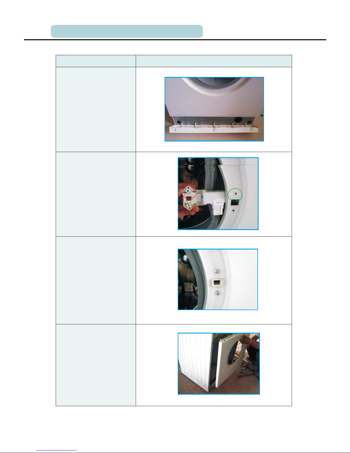
1 Undo the back cover
Undo two screws fit
between back plate and
cabinet, and then pull out
the back plate
2 Undo top cover
Undo 2 screws fit
between the top cover and
back cabinet
Push back the top cover
15mm until it leaves away
from, the control panel,
and then take it down.
3 Undo the control panel
Departing the top cover
(means as above)
Draw out the detergent
drawer
Loosen two screws fit
on the control panel
(facial).
Loosen two screws fit
on the control panel(top)
Press three clasps
between top control panel
and panel support.
Take out the control
panel inclined from the
cabinet
.
①
.
②
①
.
②
.
③
④
.
⑤
⑥
.
(5.0/6.0/7.0 counterweight)
(4.5kg counterweight)
Page 37
P.37
Operation step Picture
4 the lower panel
Open the filter cover,
release the screw on the
lower panel.
Turn the washing machine
back at an angle, pinch the
clasp ,and push it out.
5 Undo the door lock
Open the door of
washing machine.
Take the outer gasket
clamp to the drum.
Remove two screws on
the door lock, and take
down the door lock.
Take out the door lock
and draw out the plug; pay
attention to the position
of the plug so as not to
connect a wrong circuit
next time.
6 Undo the front plate
Undo the door lock
(methods as followed).
Remove the lower
cover(methods as
followed).
Undo
①
②
①
②
③
④
①
②
5.UNPACKING WAYS OF MAIN PARTS
Page 38

P.38
Operation step Picture
③ Undo five screws in
the front plate.
④ Put the front plate up
to the clasp of the front
plate away from the
loading holder, and then
take off the front plate.
8 Undo the gasket
① Undo the top cover,
control panel, lower cover,
machine door and the front
plate(methods as
followed).
② Remove the outer
gasket clamp between the
door seal and the front
plate.
③ Loosen the inner gasket
clamp between the door
seal and the front of the
outer tub, and take out the
gasket.
5.UNPACKING WAYS OF MAIN PARTS
7Undo the facade
counterweight
Undo the front plate
(methods as followed).
①
Remove six screws pull
②
out the facade
counterweight.
Page 39

P.39
Operation step Picture
10 the detergent Undo
box
① the top cover Undo
and the control panel
().methods as followed
② Release the hose clamp
and pull out the inlet hose.
③ Release the hose clamp
and pull out the detergent
box hose, and then take
out the detergent box.
11 the inlet valveUndo
① Remove the top cover
().methods as followed
② Undo 2 screws between
cabinet and inlet valve.
5.UNPACKING WAYS OF MAIN PARTS
9 Undo the PCB panel
Undo the top cover
and control panel(methods
as followed).
Page 40

P.40
Operation step Picture
12 Undo the pressure
switch
① Undo the top cover
(methods as followed).
② Pull out the plugs on the
pressure switch. Mind the
position of the plug to avoid
error during the following
assembly.
③ Loosen the pressure switch
hose clamp, and pull out the
hose from the pressure switch
interface.
④ Rotate the pressure switch
anticlockwise by 90º, and then
pull out the pressure switch.
13 Undo the pulley
① Undo the back cover
(methods as followed).
② Rotate the pulley and at
the same time pull out the belt,
and then remove the belt.
③ Remove the screw on the
pulley and then take down the
pulley.
5.UNPACKING WAYS OF MAIN PARTS
③ Release the clamp
fixing the inlet valve and
the inlet hose, and then
pull out the inlet hose.
Take out the inlet valve
and plug. Pay attention to
the position of the plug so
as to connect a wrong not
circuit next time
Page 41

P.41
Operation step Picture
15 Undo the absorber pin
① Undo the front plate
(methods as followed).
② Use pliers to pinch the
absorber pin’s
protuberance, and knock
the absorber pin out from
back lightly; in the same
way, remove the other one.
16 Undo the filter
① Open the filter cover.
② Rotate the filter knob
anticlockwise, and then
pull
out the filter.
17 Undo the drain pump
① Undo the top cover,
control panel, lower cover
and front plate(methods as
followed).
② Nip out clamp between
the drain hose and the
drain pump, and then pull
out the drain hose.
5.UNPACKING WAYS OF MAIN PARTS
14 Undo the upper
counterweight
① Undo the top cover
(methods as followed).
② Remove three screws
fit on the upper counterweight
and then pull out the upper
counterweight.
(4.5kg counterweight)
(5.0/6.0/7.0kg counterweight)
(4.5kg counterweight)
(5.0/6.0/7.0kg counterweight)
Page 42
P.42
Operation step Picture
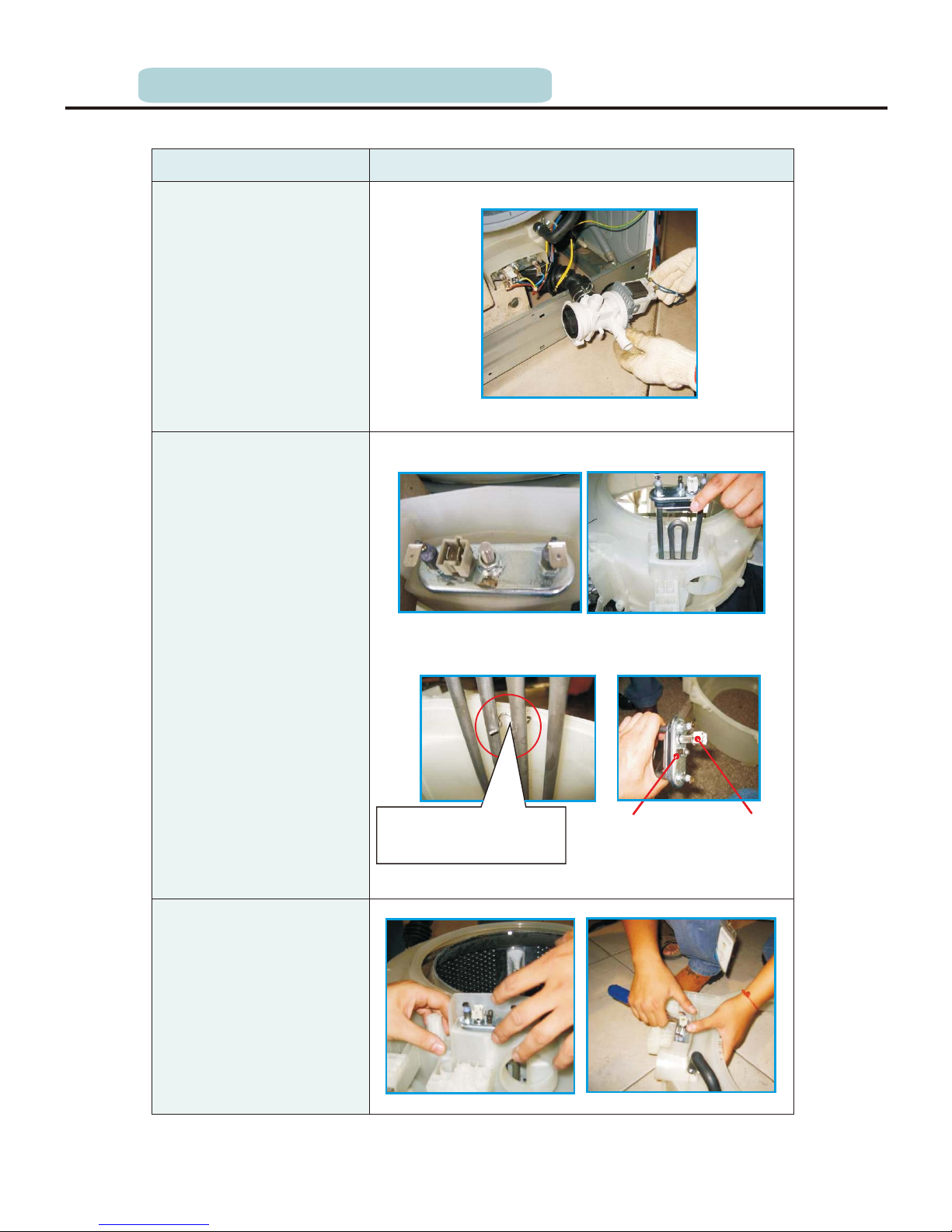
18 Undo the heater
① Undo the top cover,
control panel, lower cover
and front plate(methods
as followed).
② Pull out the heater
plug. Pay attention to the
position of the plug so as
to not connect a wrong
circuit next time.
③ Release the screw
fixing the heater.
④ Take out the heater.
19 Undo the NTC
temperature sensor
① Undo the top cover,
control panel, lower cover
and front plate(methods as
followed).
② Undo the NTC with
special tools.
Heater
NTC
In the red circle it is the
heater support, clamping
the heater.
5.UNPACKING WAYS OF MAIN PARTS
③ Nip out the clamp
between the outlet hose
and the drain pump, pull
out the outlet hose.
④ Loosen the screws
fitted on the drain pump,
and then pull out the drain
pump.
Page 43

P.43
Operation step Picture
21 Undo the panel support
① Undo the top cover
(methods as followed).
② Undo the control panel.
③ Remove two screws
fixing the panel support,
and then remove it.
22 Undo the drum tub
assembly
① Remove the motor in
24(methods as followed).
② Pull out the heater.
③ Remove the belt.
④ Remove the screws
fixing the pulley, and then
take out the pulley.
5.UNPACKING WAYS OF MAIN PARTS
20 Undo the door glass
① Open the door, remove
two screws fixing the
hinge and front plate, and
then remove the door.
② Remove six screws on
the inner door.
③ Remove the outer door
and the inner door with
special tool.
④ Take out the door glass.
Page 44

P.44
Operation step Picture
23 Undo the absorber
① Lift out the outer tub kit
(means as 21 above).
② Undo the absorber pin
between absorber and rear
tub, remove the absorber.
24 Undo the motor
① First let the machine lie
down on the back and then pull
out the motor wire and
grounding wire. Use spanner to
remove the motor screw, and
lift up the motor with the other
hand in case of falling to the
drain pump.
② After two screws are
removed, change the motor.
First support it to clasp the
correct position, then install
the screws, and then install the
belt.
5.UNPACKING WAYS OF MAIN PARTS
⑤ Remove the screws
fixing the front and rear
tub, and then remove the
tub.
⑥ Remove the inner
drum kit.
减震器销
密封条
Pin
Airproof Ring
Page 45

P.45
6.TROUBLESHOOTING
During the failure diagnosing and changing components, please do it as following:
1)There is some static harm to the electrical
parts from colophony in the washing machine
or humans. So it is better to eliminate the
potential static by grounding the humans or
touching the plugs.
2)The rated voltage of the SCR in PCB is
220-240V, so it's possible to be electrical
shock. Please take care while strong and
weak electricity is alternative.
3)The design of PCB is out of failure, so
prohibit to change the PCB panel according
to its alarm. Please do it according to the
failure diagnose program.
6.1 The circuit program & wiring connection figure
SICILY circuit principle
POWER SUPPLY PLUG
Pressure
switch
P
S10
S9
S8
M1
M5
M8
M9
M
T
M3
M4
M10
S3
S6
S2
Option
Hot valve
Main valve
Pre valve
S7
#3
#1
#2
PTC
S5
S4
H
Heater
EMI filter
AC source
Power switch
Pump
Stator
Rotor
Tacho
Motor
Wash NTC
Door lock
N
N
NLL
PE
PE
L
1
2
3
6
1
2
1
5
S8-1
S8-2
S8-3
S8-4
S8-5
S8-6
S8-7
S8-8
S8-9
S5-1
S5-2
S5-3
S5-4
S2-5
S2-4
S2-3
S2-2
S2-1
S6-10
S6-9
S6-6
S6-4
S6-2
S7-1
S7-2
S6-8
S6-7
S6-5
S6-3
S6-1
Page 46

P.46
SICILY harness connection
6.2 PCB wiring figure
1
2 Heater harness
3 Motor harness
4 Drain pump/NTC
harness
5 Water Value
6 Filter harness
Door lock harness
6.TROUBLESHOOTING
112
3
3
4
5
6
70
MR10
MR
MR5
MR4
MR3
GD4 黄绿色
MR2
MR1
MN 2
ML 1
PN 1
PL 2
70
100
90
T30R扎扣
T18R扎扣
插销式尼龙扎带
MN
FLN
FLL
FL
1
连接器 FAF 280232-0
FLN(白色) FLL(黑色)
MR6
MR7
MR9
MR8
70
70
10
10
10
45
45
A2
A1
MR6
MR5
80
80
G10
G1
G3
G5
PPN
PPLB6B3
P
S3
S2
S5
E3
G7
0.3
端子 AMP/FAF 737439-2
连接器 LBS DR250-2C 白
端子 AMP/FAF 737440-2(压接双股线)
端子 AMP/FAF 737439-2
连接器 LBS DR250-2C 蓝
压接端子 AMP/FAF 737440-2
标签
0.75
F1
AMP/FAF
175057-1
0.75
AMP/FAF 41332
FLL
F4
E2
DX3
DX2
DX4
DX
DX1
空
0基准
90
45
80
TS1 蓝色
TS2 白色
HRN WS3
HRL E1
GD2
AMP/FAF
175057-1
连接器 FAF 50016HS-2
压接端子 AMP 927831-2
连接器 FAF 280232-0
B5WS1
WS2
WS3
B1
E4
HRN
WS
端子 AMP/FAF 737439-2
连接器 FAF 280232-0白
端子 AMP/FAF 737440-2(压接双股线)
连接器 LBS DR250-2 PA-白
T18R扎扣
60
门锁线 ½º 线
90mm黑胶带
端子AMP:63688-1
连接器 FAF 280232-0
端子AMP:63688-1
DX3
50
GD1 黄绿线
80
T18R扎扣
AMP/FAF 41332
1.0
140mm耐磨胶布,均匀缠绕一层
每圈缠绕重叠胶布宽度的1/2
后面尺寸从耐磨胶布最右边量起
耐磨胶布
端子 AMP/FAF 737439-2
插销式尼龙扎带
外面用耐磨布胶固定
连接器 FAF 280232-0
16AWG
A
A2
A1
MR3
MR4
蓝色 0.75
橙色 0.75
连接器 FAF VH-2Y
压接端子 FAF VH-PT
S1
S2
S3
S4
S5
PL
ML
MN
S
连接器 FAF VH-5Y
压接端子 FAF VH-PT
G5
G6
G7
G1
G2
G3
G4
G8
G
G9
G10
MR7
MR1
MR9
MR10
MR8
连接器 FAF VH-10Y
压接端子 FAF VH-PT
B5
B6
B7
B1
B2
B3
B4
B8
B9
E
FLN
HRL
E4
E3
E1
E2
F
B
F1
F2
F3
F4
TS2
TS1
DX1
FLL
PPL
PPN
WS1
WS2
DX2
WS3
连接器 FAF VH-9Y
压接端子 FAF VH-PT
连接器 FAF VH-4Y
压接端子 FAF VH-PT
橙色
0.3
黄色
0.3
蓝色
0.3
蓝色1.0
灰色1.0
棕色1.0
蓝色16AWG
棕色0.5
蓝色0.5
蓝色
0.5
蓝色0.5
棕色
0.5
白色
0.5
棕色
0.5
红色
0.5
棕色
0.75
橙色
0.75
蓝色
0.75
白色
0.75
红色
0.75
连接器 FAF 520987-1
压接端子 KET ST730268-3
连接器 FAF YTH500-10P
端子 AMP 964201-2
a
a
Page 47

P.47
The alarm display is as below :
6.3 Schedule of failure alarm & its disposal
6.TROUBLESHOOTING
Door lock
problem
Door is not closed properly.
Restart after the door is closed
Reason
Solution
Description
Display
LED
Please call up service line if there are still troubles.
Drain problem
while washing
(drain time
exceeds 3 minutes)
Water injecting
problem when
washing (water
injecting time
exceeds 7
minutes)
Tap is not opened or water
flows too slowly.
Inlet valve filter is blocked.
Inlet pipe is twisted.
If water is not supplied
Open the tap or wait till
the water supply
becomes normal.
Check inlet valve filter.
Straighten the water pipe
Check the other taps in
the room.
Please call up service line if there are still troubles.
Please call up service line if there are still troubles.
Outlet hose is blocked or twisted
Drain pump is blocked
Wash and straighten outlet hose.
Wash drain pump filter
Please call up the service line if there is any other problem.
E30
E10
E21
Please call up service line if there are still troubles.
Please call up service line if there are still troubles.
Please call up service line if there are still troubles.
E12
E60
E61
Overflow protection
: The water
level exceed
overflow level.
The machine lock the door,
close inlet valve, motor
stop working, drain water
in error status.
1. Re- start machine;
2. Change inlet valve.
Motor stalling
warning: Motor
try to start
working 5 times
every 1 min.
The machine lock the door,
close inlet valve, motor
stop working, drain water
in error status.
1、Check motor wire;
2、Change PCB;
3、Change motor
Speed measuring
signature lost
warning: PCB
cannot detect
speed signature
during working.
The machine lock the door,
close inlet valve, motor
stop working, drain water
in error status.
1、Check motor wire ;
2、Change motor.
Page 48

P.48
6.4 Electrical parts working & testing principle
1. Inlet valve
Working principles:
A piece of iron core blocks in the inlet valve, and
one side of the iron core is the push exerted by
spring. When the power is turned on, the winding
in the valve will generate a force to pull the iron
core up, and then the inlet passage is smooth and
the water flow in the drum under the household
water pressure .
Technique datas:
Maximum input voltage: 220-240V
Frequency: 50/60Hz
Resistance: 4.13K ±10%
Flux: 8L/min ±15%
Water pressure: 0.2-10bar
Temperature of hot water: Maximum 25℃
The testing methods of inlet valve is as follows:
1) Use the multimeter to test the electromagnetism
valve resistance, which should be 4.13k ±10%.
If the value is infinite or approaching to zero,
the valve is invalid and can't let water enter.
2) Connect the inlet valve and tap, if water flows
out of the outlet without power being off, the
iron core is invalid and should be replaced.
Ω
Ω
6.TROUBLESHOOTING
Page 49
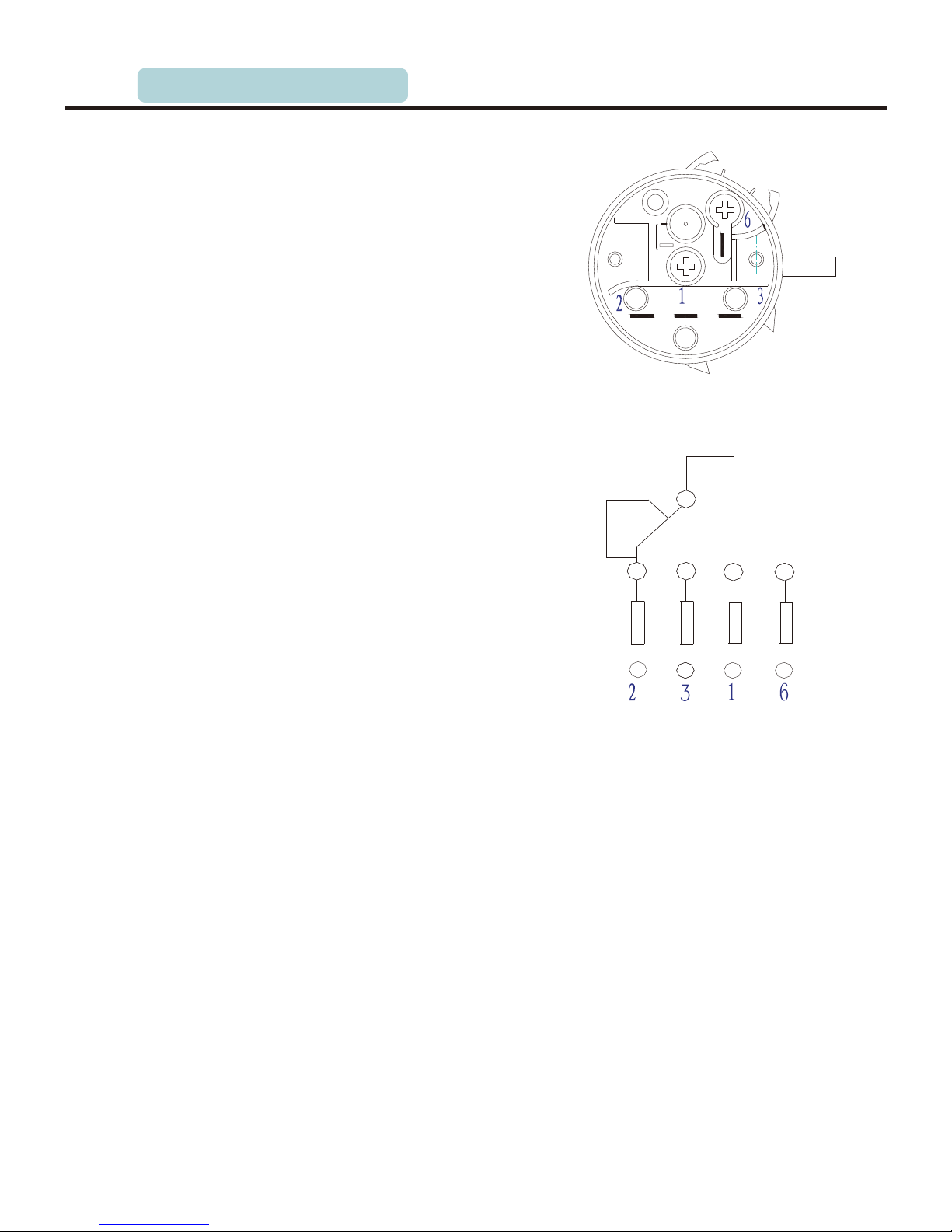
P.49
2. Pressure switch
Pressure switch, which use the water pressure to
control its spring, connects different control circuit
through contacting different contractor.
Pressure switch has two groups of pressure control
point: point 1 connects point 2 in normal state
without water, when the water level is up to a
certain value, point 3 connects point 1 under the
water pressure, providing power to the heater
through point 3 and making signal of the water
level to the control panel. When the water level is
too high, points 1 connects drain pump directly
through point 6 and then feedback the signal of
overflow to the PCB panel.
Technical parameters:
1) Main touch point subsection capacity:
Point 3: 16(4) A/250V on/off
Point 2: 10(2.5)A/250V on/off
2) Overflow protection point subsection capacity:
1A/250V on/off
The test methods of water level switch:
1) In normal state without water, points 1 and 2
connect and points 1 and 3 disconnect, if points
1 and 3 connect without water, the water is not
in and appear interference malfunction, it should
be replaced.
2) Huff the switch and if it leaks breath, the inlet
will be endless. It should be replaced.
3) When the water pressure reach 98mm of water
column, points 1 and 3 connect. If not connected,
it may appear the malfunction of endless inlet.
6.TROUBLESHOOTING
Page 50

P.50
3. Door switch
Function:
There are three connection in the door lock, 1 and 3
provide 220V voltage to the PTC, when the door is
close and power is on, PTC will be distortional, then
push the middle spring, the points 2 and 3 connect
with spring provide power to the peripheral load
(motor, pressure switch etc). Meanwhile the plastic
bolt in the peripheral spring will insert into the door
lock channel outside and Only when the
power is off about 2 minutes, PTC will get back. At
this time the door can be open.
Technical rated:
120V/240V, 16A, PTC
Input voltage: 253VAC
Rated current: 50mA
Start-up current:
The testing methods of door lock are as follows:
1) The contractor 2 and 3 are disconnection when the
door lock is off (if not, the door lock should be
replaced). Supply power to the contractor 1 and 3
(220VAC) 10s, and then turn off, the contractor 2
and 3 will be connection in 30 s, if not, the door
will not be locked and should be replaced.
Supply power (220VAC) to the contractor 1 and 3
10 s and then turn off, if the contractor 2 and 3 are
connection, the door lock should be replaced.
self-lock.
2.5A for max.
6.TROUBLESHOOTING
PTC
1
3
2
Page 51
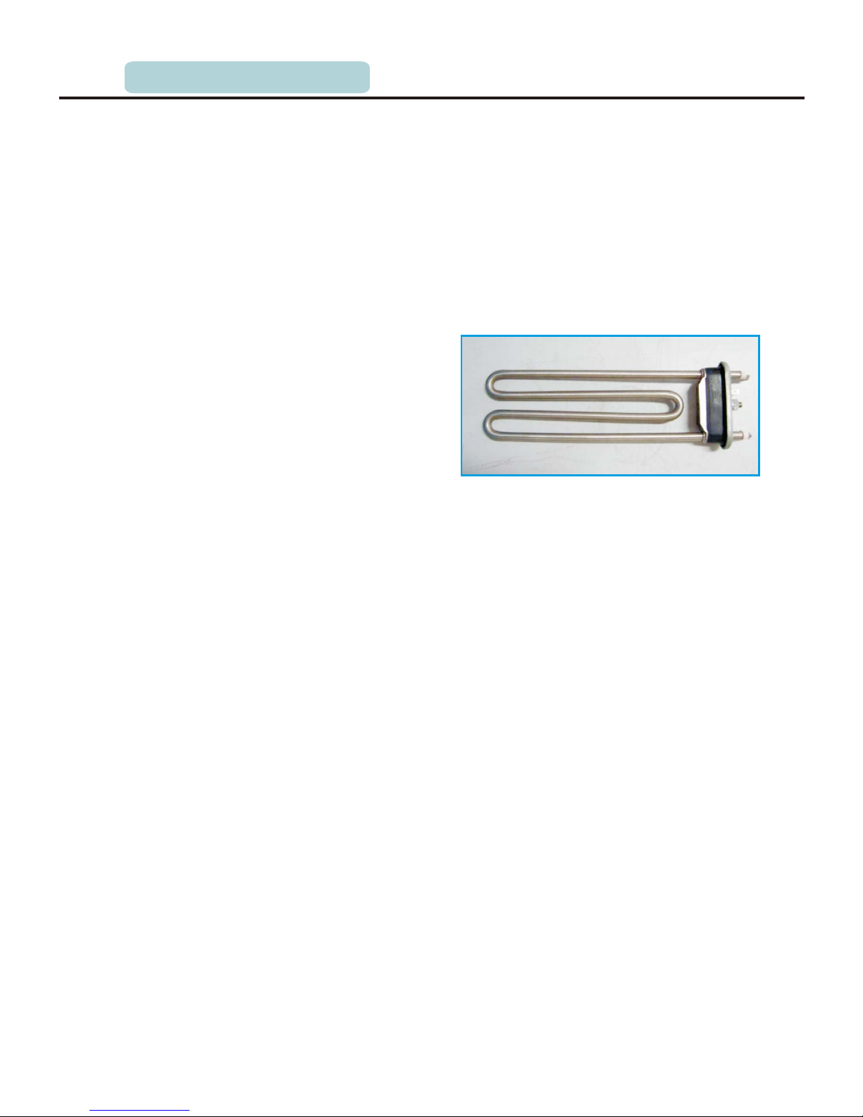
P.51
4. NTC and heater
The normal working range of NTC is -7℃ to 105℃.
The higher of the temperature, the lower the
NTC’s resistance value. While the heating
temperature will be tested through testing the
NTC’s resistance value. NTC is inserted in the
resistance’s flange, which seal ring guarantee
the airproof quality. You should loosen the lock
facility in order to replace the NTC.
NTC parameters:
R/t speciality: ℃
Resistance speciality:
Temperature range: -7℃-105℃
Resolution: ≤1k
Tolerance: ±2.5℃
Test condition:
Heater parameters
Voltage: UN±1%
Rating power: 1800W
Rating voltage: 230VAC
Power tolerance: +5% -10%
Resistance: About 300
.
: NTC’s resistance value is 2815 ±3.5%
at 25℃,
t is about 27 ,
5. Drain pump
When the power is on, it will drain water with its impeller.
Technical parameters:
Voltage: 220V
Frequency: 50 Hz
Power: <40 W
Capacity extent: 1 m
Flux: 13L/min
The methods of testing drain pump:
1) It's resistance value is about 240 tested by multimeter, if the value is zero or infinity,
it need to be replaced.
2003,Tn=60 ,
dRn=2% and dB= 1%
R(25) = 4.828 kΩ± 3.5 %,
R(100)= 330Ω ± 3.3 %
~
Ω
Resistance is made up of two heat fuses which can’t be replaced and integrative (the
insurance facility preventing heating without water)
The testing methods of NTC are as follows: Ω
if its value is zero or infinity, the NTC is fault and should be replaced.
The testing method of heater is as follows: he resistance value of heater Ω
if its value is infinity, the heater is fault and should be replaced.
Ω
6.TROUBLESHOOTING
Page 52

P.52
2) Take off the filter cover and check whether the
impeller is blocked, clean up it and then
assemble it.
6. Filter
In order to decrease the inter-interference
between the washing machine and the power
grid, L2 and the power grid’s L connector, N4 and
the power grid’s n connector, U1 and washing
machine’s L connector, U3 and washing machine’s
N connector.
Filter parameters as follows:
0.68M +2×1mH+0.47μF+2×0.1 F
7. Series motor
The motor’s rotate is controlled by SCR, the
bigger of the through angle is the higher of its
voltage and motor’s speed are, or else,
diminishing the through angle can reduce
the motor’s speed.
The motor’s turning is controlled by two relays,
when 5 and 8 connector, 9 and 10 supply power,
it is clockwise from the shaft direction, when 5
and 9 connect, 8 and 10 supply power, it is
anticlockwise then.
The speed-measuring facility in the motor
transform the speed into impulse number
which was provided to the PCB panel (the higher
of the rotate speed, the more of the impulse is), the
PCB panel control the motor’s speed through SCR.
The methods of testing motor:
1) When the resistance between 6 and 7 is infinite,
the motor appears heat protection, when 6 and 7
is always cut, the motor should be replaced.
2) If the resistance between 5 and 10 or 8 and 9 is
infinite, the motor should be replaced.
Ω μ
Heat protecter
Speed tester
6.TROUBLESHOOTING
Page 53

P.53
6.5 Service Mode
6.TROUBLESHOOTING
Before e ntering into service mode, m ake sure no water r emains in the inner drum, if not, select drain
only pro gram to drain them out.
Tur n on the machine an d press Delay and Temperature in proper or der for 30s to en ter into servic e
mode. Press Delay or Speed to select test program. Press Start/pause button to confirm your selection
and start the selected test. If you want to go back to test selection interface, press the Start/pause
button to cancel previous selection.
6.5.1 Version switchover (t01)
1) Enter i nto service mod e, LED displa ys “t01”
2) Press Start/pause button, LED displays “0xx”.x means
3) Press Delay to confirm switchover.
4) Press Speed to change version.
5) Press Delay but ton continuously for 3s to con firm your chang e.
6) Press Start/pause bu tton to close all output and exi t this program. L ED displays “t01”.
6.5.2 Error code checking (t02)
1) Enter i nto error code mo de, LED displ ays “ELT”. Pres s Delay button and LED displays
EXX(x=1,2,3….)
2) Press Delay to s how the last code and press Spee d to show the next co de. Th e latest 10 err or codes
can be fou nd in system, and same error cod e is recorded one t ime even if it occurs more than one time
3) If no error information found, LED shows E00.
4) Press Delay continuously for 3s, after hearing the beep, all the error codes records deleted, LED
displays E00.
5) Press Start/pause but ton to exit, LED display t02.
6.5.3 Version information checking (t03)
Version information checking is used to show the current version information stored in nonvolatile
memory applications.
1) Enter i nto service mod e, LED displa ys “Sut”.
2) Press Delay button, LED displays repeatedly “cod” and v ersion number “0xx” repeatedly each for
1s.
3) Press S tart/pause to go back to versi on informatio n checking st atus, LED displ ay “t03”.
6.5.4 UI Checking (t04)
1) Press Start/pause but ton to illuminate the whole LE D display.
2) Press Delay but ton, the whole LED display fla shes.
3) Press Start/pause to s top flash, LED display “t04”
6.5.5 Drain pump checking (t05)
1) Enter i nto service mod e, LED displa ys “PPt”.
2) Press Delay button to drain out all the remaining water. If all water drained ou t, LED displa ys
“EP”
,and 6 minu tes later ,if the re is still wat er remains in it, L ED displays “FP”.
3) Press Start/pause bu tton to exit, LED displays “t0 5”
6.5.6 Pressure switch checking (t06)
1)Enter into service mode, drain out the water, LED displays EPT.
2) Press Delay button to activate inlet valve. LED displays L1 once water lever get the main wash
level.
3) Press D elay to close inlet valve, LED d isplays “t06”
4) Press Start/pause bu tton to exit, LED displays “t0 6”
6.5.7 Water temperature sensor and heater checking (t07)
1) Enter into service mode, drain out the water, LED displays the c urrent temper ature of inne r drum.
2) If wate r switch works,
3) Press Delay button to activate the main inlet valve and get the water lever to heating level then turn
on the heater and 5 min later turned off automatically.
4) After heater turned on, LED displays the current temperature. Detect the real temperature of inner
drum and c heck with the numbers on the dis play.
5) Press Start/pause but ton to exit, LED displays “t07 ”
Page 54

P.54
6.TROUBLESHOOTING
6.5.8 In let valve che cking (t08)
1
)Enter in to service mode , drain out the w ater, LED disp lays “uLt”
2
)Press Delay button, LED display s “u2”and switc h on the main was h inlet valve for 1 0 min.
3) Press Delay bu tton, LED displays “u1” and tu rn off t he main wash inle t valve and switch on
prewas h valve for 10 min.
4) Wait 10 min o r press Delay button to turn off prewash valv e and switch on hot w ater inlet
valve (o nly for double-inlet model s) and LED displa ys “u3”.
5) Press Delay but ton to switch on main wash and pre wash valve and ge t the water lever to setting
level, if water level can't reach setting level within 5min or exceeds setting level. Drain out the water.
6) Press Start/pause to e xit, LED displays “t08”.
6.5.9 Rotating checking (t09)
1) Enter i nto service mod e, LED displa ys “tt”
2) Press Delay but ton, inner drum rotates in 45r /m clockwise fo r 15s and stop fo r 10s then rotate s
counte rclockwise for 15s, over and o ver again.
3) Press Start/pause button to turn off the motor and exit, LED displays “t09”.
6.5.10 Spin speed checking (t10)
1) Press Start to en ter into service mode, LED dis plays the curre nt speed. The number on the display
goes up in the same pace with the real speed and when it reach 400rpm, you need to press Delay
button to get the machine to reach its target speed.( if declared speed ≥1000rpm, target speed is
1000rpm and if declared speed <1000rpm,target speed is its declared speed)
2) Press Start/pause bu tton to exit and LE D displays “t 10”.
Page 55

P.55
6.6 Fault tree
Reliable connection
Y
N
Whether the connect
is well
Change NTC
Y
N
Whether NTC is short
or open circuit
Y
Whether the pressure
switch is well or not
N
Y
Choosing new heating
temperature
Y
Whether to set up
non-heating
Non-heating
Whether the heater
is well
N
Change the heater
Y
Change the control panel
Maintenance 1. non-heating malfunction
6.TROUBLESHOOTING
Page 56

P.56
2. Door non-locked & its maintenance
Close the door correctly
Whether the door is
closed correctly
Y
N
N
Push the start button
to start the program
N
Reliable connection
The door is
invalid and should
be replaced
lock
Y
Y
Y
Y
N
Door non-locked
Whether push the
start /pause button to
start theprogram
Change
the control panel
Whether the voltage
between harness 1 and
harness 3 is about 220v
Whether the harness
connection between the
door lock and the main
board is well
6.TROUBLESHOOTING
Page 57

P.57
Change main board
Y
Whether the
connection is well
N
Door is invalid and
should be replaced
lock
Y
N
Y
Whether the door
is closed correctly
N
Y
Y
Whether the tap is opend
Y
No water inlet or
water inlet overtime
N
Y
N
Y
Y
N
N
N
Change the inlet valve
N
N
Change the control panel
Whether the
switch is well
pressure
Y
N
Y
Push start/pause button
Cleaning with brush
Change the
switch
pressure
3. No water inlet or water inlet overtime
Whether press
start/pause button
after choosing the
program
Whether door
lock 3 and 2 is
connected correctly
Whether the voltage
between door lock 1
and 3 is 220V
Whether the
electromagnetic
valve buzz
Whether the
connections of inlet
valve is well
Whether the inlet pipe
is fold or the water is
cut off
Whether the
inlet valve coil is
well
Whether the inlet filter
net is blocked
Whether the
connection of
pressure switch is
well
Connect
connections
6.TROUBLESHOOTING
Y
Page 58
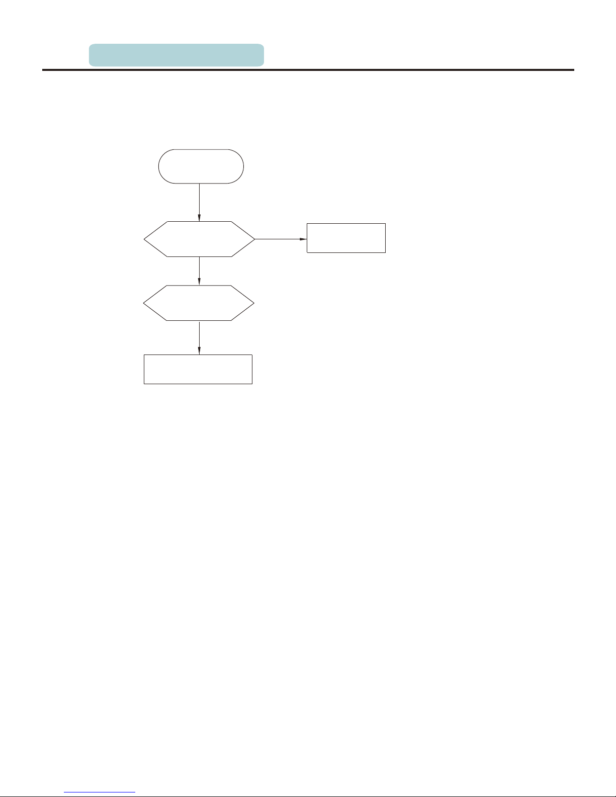
P.58
4. Heating beyond the setting temperature its maintenance
Change NTC
Y
Whether the
connection is well
N
Whether NTC is
short circuit or
open circuit
Y
加热过度
Y
Change the control panel
Over heating
6.TROUBLESHOOTING
Page 59

P.59
N
Y
N
Whether the
door lock is
well
Close the door
Whether the
door is closed
Y
Y
Non-drain or
overtime drain
Change
panel
the control
N
Reliable connection
N
N
Y
Return to the normal station
Change the
drain pump
Y
Cleaning the
filter
N
Y
N
Y
Y
5. of non-drain or drain exceed the setting time Maintenance
Whether it is in
the state of pause
Push start/pause button
Whether the
pump is vibrating
Whether the
connection between
the pump and the main
board is loosened
Whether the
pump is blocked
or burned out
Whether the filter
is blocked
Whether the drain
pipe is fold or hung
too high
6.TROUBLESHOOTING
The means of detecting door
switch refers to the paragraph
of "no water inlet".
Page 60

P.60
6. Water inlet overflow malfunction maintenance
Hang the hose well
Whether the drain
hose is hung up
Y
N
Y
C
inlet valve
hange the inlet
Y
N
Reliable connection
Y
Y
N
Y
N
Water inlet overflow
Whether the electric
connection of pressure
switch is normal
Change the control panel
Whether the water
is in without power
Whether the gas pipe
or the connection is
leaking or deadlock
Change or revive
the gas pipe
Whether the
switch is well
pressure
6.TROUBLESHOOTING
Page 61

P.61
7. Drum non-rotating malfunction maintenance
Change the control panel
N
The drum is blocked
Drum non-rotating
Y
Whether the door
is closed correctly
Close the door
Whether the door
lock is well
Y
N
Change the door lock
N
Y
Y
Y
Whether the motor
is well
Whether the
connection of main
and auxiliary wiring
harness is well
N
Reliable connection
Y
Whether the inlet
is correct
N
Waiting inlet or inspect
overtime water inlet
malfunction
Whether the
switch is well
pressure
Y
Y
N
Replace it
N
Replace it
Detach strap,
whether the drum
is rotating flexibly
6.TROUBLESHOOTING
Page 62
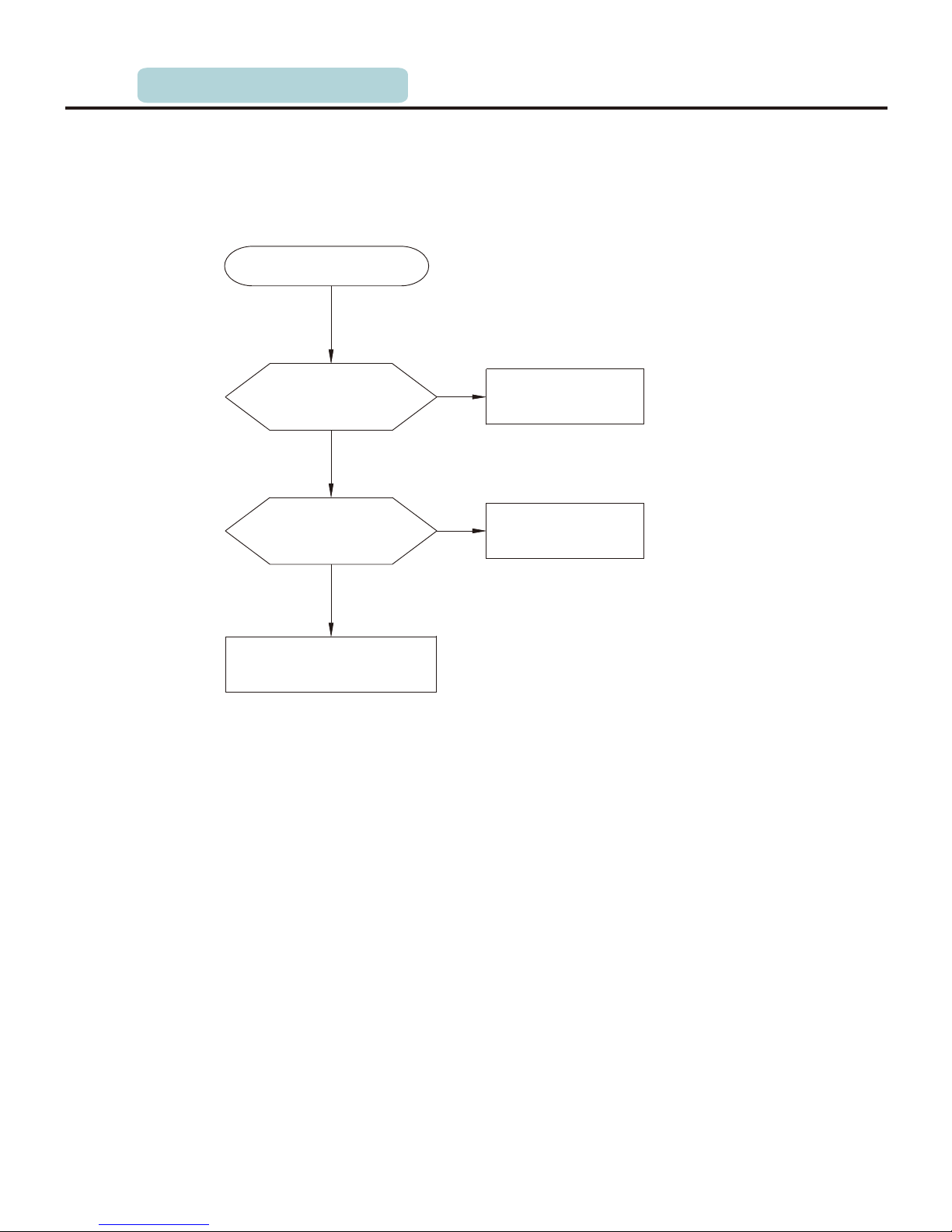
P.62
8. water inlet and water outlet at the same time Maintenance
Whether the washer is
disposing the foam in
the drum
Change the control panel
N
Y
Normal phenomenon
Y
Water inlet and water outlet
at the same time
Whether the drain hose
is hung too low
N
Y
Hang the hose well
6.TROUBLESHOOTING
Page 63
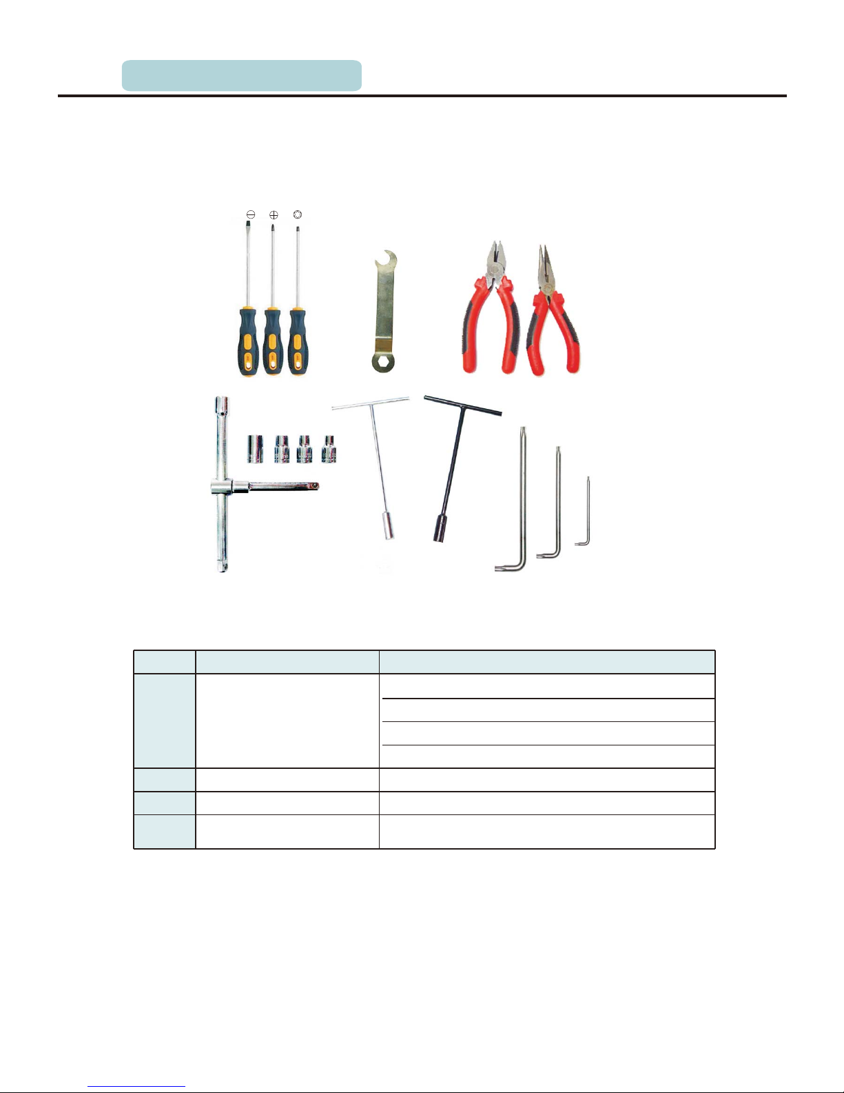
P.63
6.7 Service tools
List
Number
Tools
Suitable kit
1
Sleeve spanner
Heater
(1)
Motor counterweight(1), (5)
Strap screw
2
Spanner
Adjust pulley screw leg and undo transport bolts
3
Pliers and pinchers
Assembling or auxiliary function
4
Other tools(screwdriver,
pliers and so on)
Common service tools
8# 10# 13# 17#
Drum tub assembly
Tools for assembly and unpacking
6.TROUBLESHOOTING
Page 64

P.64
6.故障诊断
7.TECHNICAL SPECIFICATION
7.1 Product technical specification parameter
Program list
Cotton Intensive
Quick 15'
Eco Wash
Sports
Mixed
Delicate
Default Time
(Min)
60
40
20
30
40
40
30
40
40
NA
NA
NA
60
40
Cold
Default
Temp.( C)
Load(kg)
6.0/7.0
1200
1400
1000
1000
1000
1000
1000
1000
0
0
1000
1000
400
400
800
800
1400
1200
1400
1200
1000
1000
800
800
800
800
1000
1000
600
600
800
800
7.0
6.0
2.0
1.5
2.5
1.5
7.0
6.0
7.0
6.0
7.0
6.0
7.0
6.0
7.0
6.0
7.0
6.0
7.0
6.0
7.0
6.0
7.0
6.0
7.0
6.0
7.0
6.0
7.0
6.0
3.5
3.0
198
201
198
201
81
81
69
69
86
86
78
78
66
66
73
73
66
66
15
15
14
14
34
34
1
1
107
107
118
118
7.0
6.0
Softener
Case
60°
40°
20°
Rinse&Spin
Drain Only
Spin O nl y
Baby Care
Page 65

P. 6
7.2
T
echnical parameters
Table of washing procedure
Model
MFG60-ES1202
MFG70-ES1403
Anti-electricity
Waterproof rating
Rated washing capacity
Rated spinning capacity
Rated voltage
Rated input current
Rated dehydration speed
Heating power
Working pressure
Rated consumption of water
Rated consumption of power
Wash performance
Energy rating
Net weight
Figure dimension (mm)
( length×width×high)
Class I
IPX4
6.0kg
6.0kg
220-240V/50Hz
10A
1200rpm
1800W
0.05~1MPa
45L /cycle
0.89kWh /cycle
1.031
A+
50kg
595×470×850
Class I
IPX4
7.0kg
7.0kg
220-240V/50Hz
10A
1400 rpm
1800W
54.5L /cycle
1.02kWh /cycle
1.031
A+
56kg
595×495×850
0.05~1MPa
Parameters
7.TECHNICAL SPECIFICATION
 Loading...