

Page 1
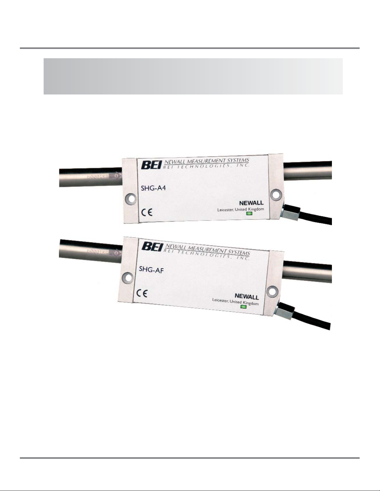
SHG-A* Absolute, SHG-TC, SHG-TS & SHG-VS
Linear Encoders
NEWALL MEASUREMENT SYSTEMS LTD
N
Installation Manual
THIS MANUAL SHOULD BE USED IN CONJUNCTION WITH WITH THE
CORRESPONDING PROTOCOL DOCUMENT
Page 2

Newall Measurement Systems
Contents
1
CONTENTS
1.0 Technical Specification..............................................1
1.1 Bracketry ..............................................................................2
1.2 Preparation ..........................................................................2
1.3 Warnings ..............................................................................2
2.0 Encoder Assembly ....................................................3
3.0 Mounting The Reader Head ......................................3
4.0 Mounting The Scale....................................................4
4.1 Double End Mounting ..........................................................4
4.2 Single End Mounting ............................................................6
4.3 Scales in Excess of 2.5 Meters............................................7
5.0 Fitting The Scale Guard ............................................9
6.0 Cable Routing ..........................................................10
7.0 Final Check................................................................10
Appendix A - Scale Bracket Mounting Options ............11
Appendix B - Dimensional Drawing ................................12
Page 3

Introduction
Newall Measurement Systems
2
1.0 INTRODUCTION
This manual will provide connection and mounting instructions for Newall's Absolute, Digital and Distance
Coded linear encoders. It is important that you read and understand this manual prior to commencing the
hardware installation. Electronic specifications can be found in the corresponding integration manual.
If you have any questions relating to this manual or installation contact Newall or your local authorised
Newall representative.
1.1 Bracketry
Due to the variety of machine types and applications, it may be necessary to design, make and fit custom
brackets for the linear encoder assembly. If custom brackets are needed, make certain they are rigid
enough not to allow any flexing or distorting while the machine is in operation. Newall offers a variety of
bracket kits to aid in the installation. Contact Newall or your local authorised representative for details.
1.2 Preparation
Prior to beginning the installation the machine should be studied to determine where the linear encoder(s)
will be fitted.
In order to reduce erroneous readings caused by machine wear, it is recommended that the scale be fitted
as close to the machine lead screw or axial drive shaft as possible.
The actual overall scale length is approximately 258mm (10.1") longer than the stated scale travel on these
SHG encoders (e.g. if SHG travel length is 40", the overall length of the scale will be 50.1").
For SHG-TS and SHG-VS outboard mounting of the scale support brackets will add approximately 20mm
(3/4") to the effective scale travel (Refer to Appendix A).
For a more compact installation, scale travels of 300mm (12") or less may be fitted by supporting one end
of the scale only by use of a single end mounting block (Refer to Figure 6.4 and 6.10).
The moving member of the linear encoder assembly can be either the reader head or the scale.
Cable routing from the reader head should be examined (See Section 8). Each reader head is provided with
either a 3.5 meter (11.5') or 7 meter (22') cable. Extension cables are available in 1 meter (3'), 2 meter
(6.5'), 3.5 meter (11.5'), 5 meter (16.5') and 10 meter (32') lengths. Contact Newall or your local authorised
representative for details.
1.3 Warnings
If for any reason the machine axis travel is greater than the actual scale travel, it is recommended that
‘mechanical stops’ are fitted to the machine to avoid damage caused by over travel. Newall will not accept
responsibility for scale and reader head damage caused by machine over travel.
Both the reader head and the scale are precision made components and it is important that they are
handled with care. By design, the linear encoders can withstand the rigors of the harsh workshop
environment. However, permanent damage can occur through bending or severe impact.
It is important that the scale be kept at least 13mm (0.5") away from any magnetic bases on indicators or
magnetic chucks.
Page 4
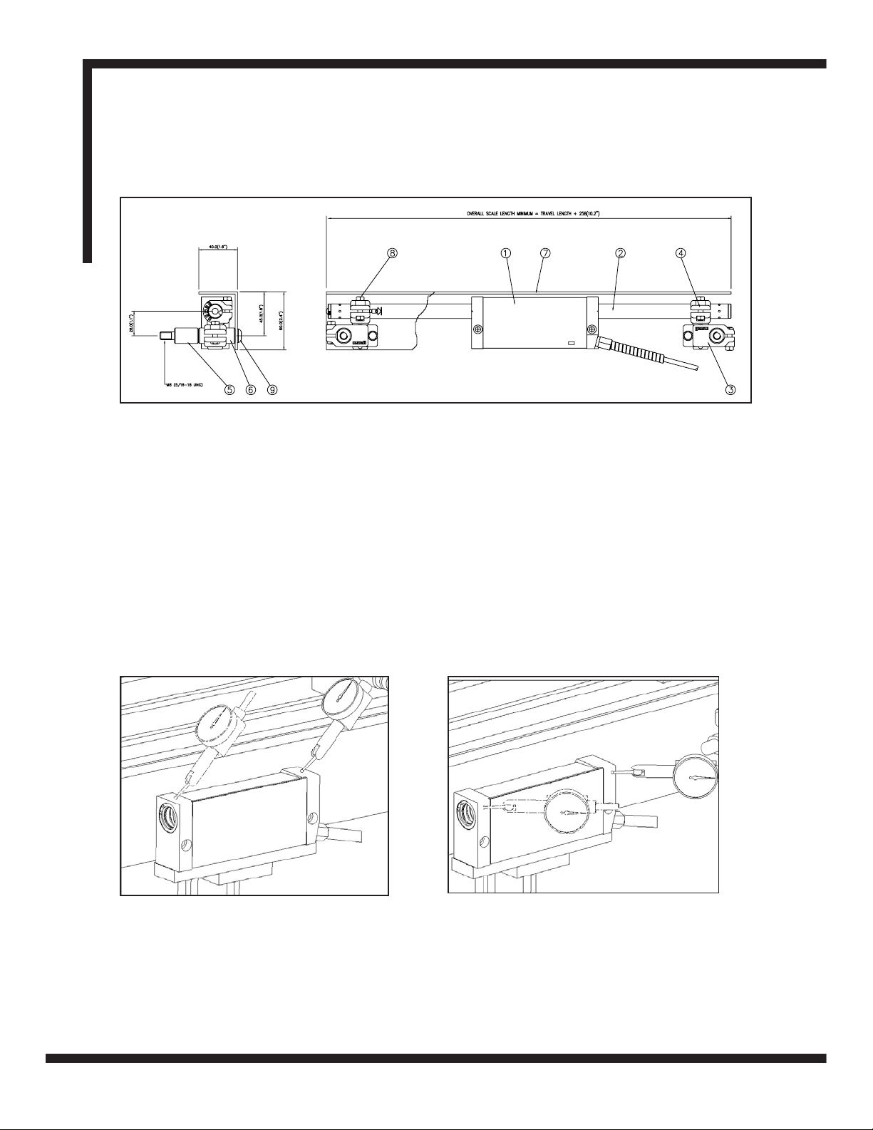
Figure 3.1 - Alignment of the reader head
2.0 ENCODER ASSEMBLY
Item Description
1 Reader Head
2 Scale
3 Scale Support Link
4 Scale Anchor Pin
5 Support Pillar Short
Item Description
6 Support Pillar Long
7 Scale Cover
8 M5 Nut
9 M8 x Socket Button Head
Newall Measurement Systems
3
Encoder Assembly / Mounting the Reader Head
3.0 MOUNTING THE READER HEAD
Mount the reader head together with its bracket(s) to the machine and secure the assembly parallel with axis travel to
within +/-0.05mm (0.002"), (Refer to Figure 3.1).
Final adjustments can be carried out by use of laminated shims, which are included with each transducer assembly.
Each layer of shim is equivalent to 0.05mm (0.002").
Less than 2.5m (100”)
Page 5
Mounting the Scale
Newall Measurement Systems
4
4.0 MOUNTING THE SCALE
4.1 Double End Mounting
Note: Refer to section 4.3 for mounting scales in excess of 2.5 metres.
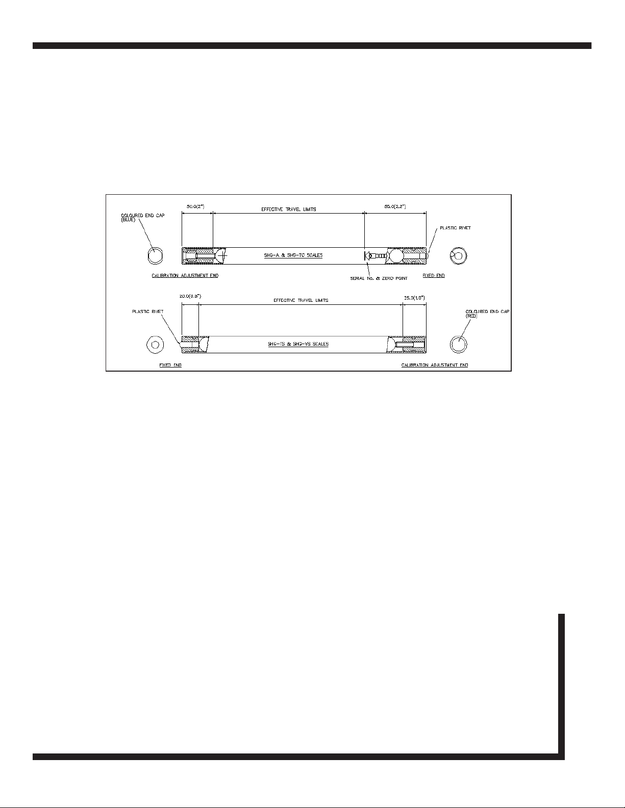
Each end of the scale is different and can be identified by the “calibration adjustment end” and the “fixed end.
NOTES:
(A) Erroneous readings will occur if the reader head is allowed to travel beyond the effective travel limits
(Refer to Figure 4.1).
(B) The pre-load on the balls are factory set via the set screw at the calibration adjustment end.
Caution: Do not tamper with or adjust the set screw as this will alter the calibration and accuracy
specification of the scale and void the warranty (Refer to Figure 4.1).
(C) When mounting scales in the vertical plane, the calibration adjustment end should be positioned at the top.
Once the reader head is secured and correctly aligned, the scale support brackets can now be fitted. The scale support
brackets consist of the support pin, the support link and the pillar(s).
Traverse the machine to its maximum position toward the non-cable entry side of the reader head. Maximum position
means all available travel, including hand winding past any electrical limits or trip dogs.
Carefully slide the scale or setup tube through the reader head, allowing for a sufficient amount of scale to project from
the reader head in order to fit the scale support brackets. Note: If the scale travel is more then 60" it is recommended
that a setup tube is used for alignment to avoid accidental damage to the actual scale tube.
Assemble the scale support link to the scale support pin leaving approximately 3mm (1/8") gap between the bottom of
the pin shoulder and the top of the link.
Slide the link/pin assembly onto the scale to approximately 5mm (0.2") away from the end of the reader head.
Transfer punch through the support link and into the machine casting. It is important that the support link is kept square
to its mounting surface at all times.
Remove the link/pin assembly and the scale from the reader head. Drill and tap M8 x 18mm deep (USA 5/16 - 18 x 3/4"
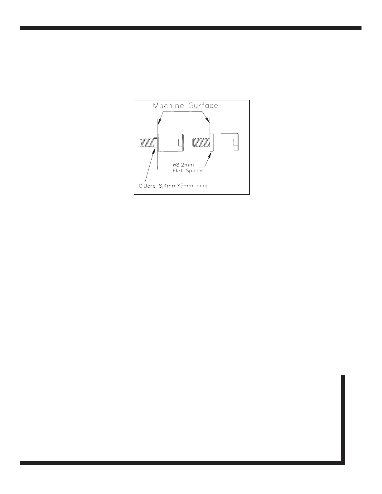
deep) into the machine casting as marked by the transfer punch. Fit the pillar(s) to the machine casting by using one of
the methods shown in Figure 4 .3. The pillar should fit square and flush to the machine surface.
Figure 4.1 -Scale
Page 6

Mounting the Scale
A maximum of two support pillars may be screwed together to allow for sufficient adjustment of the scale. If two pillars
are insufficient to enable the scale to be mounted, then additional brackets will be necessary. These brackets must be
sufficiently rigid to eliminate any axial movement of the scale.
Loosely fit the support link/pin assembly onto the pillar and pass the scale through the reader head and into the support
pin. While gently sliding the scale forward and back 25 - 50mm (1 - 2") through the support pin, carefully tighten the hex
screws on the support link, ensuring that the scale slides smoothly through the reader head and into the support pin. If
any interference is detected then fully loosen the hex screws on the support link and repeat this step.
Note: Do not force the scale through the Support Pin.
IMPORTANT WARNING:
THE CENTER LINE BORE OF THE READER HEAD MUST BE IN DIRECT ALIGNMENT WITH THE
CENTER LINE BORE OF THE SUPPORT PIN. PERMANENT DAMAGE TO SCALE AND/OR
ERRONEOUS READINGS WILL OCCUR IF THIS WARNING IS NOT FOLLOWED (REFER TO FIGURE 4.2).
Remove the scale from the reader head and traverse the machine to its full extent in the opposite direction.
Full extent means hand winding past electrical limits.
Assemble the scale support link to the scale support pin leaving approximately 3mm (1/8") gap between the bottom of
the pin shoulder and the top of the link.
Slide the link/pin assembly onto the scale making certain that there is sufficient clearance between the reader head and
the support link to prevent damage to the reader head cable. Do not secure the support pin to the scale at this time.
Transfer punch through the support link and into the machine casting. It is important that the support link be kept square
to its mounting surface at all times.
Figure 4.2 - Reader head and bracket alignment
Newall Measurement Systems
5
Page 7
Mounting the Scale
Newall Measurement Systems
6
Remove the link/pin assembly and the scale from the reader head. Drill and tap M8 x 18mm deep (USA 5/16" -18 x 3/4"
deep) into the machine casting as marked by the transfer punch. Fit the pillar(s) to the machine casting by using one of
the methods shown in Figure 4.3. The pillar shoulder fit square and flush to the machine surface.
A maximum of two support pillars may be screwed together to allow for sufficient adjustment of the scale. If two pillars
are insufficient to enable the scale to be mounted, then additional brackets will be necessary. These brackets must be
sufficiently rigid to eliminate any axial or radial movement of the scale.
Loosely fit the support link/pin assembly onto the pillar and pass the scale through the reader head and into the support
pin. While gently sliding the scale forward and back 25 - 50mm (1 - 2") through the support pin, carefully tighten the hex
screws on the support link, ensuring that the scale slides smoothly through the reader head and into the support pin. If
any interference is detected then fully loosen the hex screws on the support link and repeat this step.
Carefully slide the scale through the support pin, through the reader head and into the opposite support pin. FULLY
TIGHTEN THE SUPPORT PIN HEX SCREW AT THE FIXED END OF THE SCALE, BUT ONLY “SNUG UP” THE HEX
SCREW ON SUPPORT PIN AT THE CALIBRATION ADJUSTMENT END.
4.2 Single End Mounting
Note: The maximum total length of the scale must not exceed 610mm (24") when using a single end
mounting kit. The single end mounting kit is sold separately, UK part number 600-63610, USA part number 294-
23010.
For SHG-A* and SHG-TC remove the nylon pan head screw from the end of the scale to access the tapped hole. For
SHG-TS and SHG-VS, remove the red end cap fromt he end of the scale to access the tapped hole.
After the reader head has been installed, slide the scale through the reader head and insert the end of the scale into
the single end mounting block (Refer to Figure 4.4).
Once the position for the single end mounting block has been determined mark the machine casting using the slot in the
mounting block as the guide. Drill and tap M6 x 12mm deep (USA 1/4 - 20 x 1/2"). Fit the mounting block using the M6
(USA 1/4 - 20") socket head cap screw and washer.
Check the alignment by gently sliding the scale through the head and in and out of the mounting block. A djustments
may be carried out by adjusting the M5 jacking screws. When the alignment is complete secure the scale by inserting
the M5 screw and washer through the mounting block and into the calibration adjustment end of the scale.
Figure 4.3 - Support pillars
Page 8

Mounting the Scale
4.3 Scales in Excess of 2.5 Meters
Traverse the machine to fullest extent of travel including hand winding past any electrical limits or trip dogs.
Insert the set up tube into the reader head, allowing for a sufficient amount of scale to project from the reader head in
order to fit the scale mounting brackets.
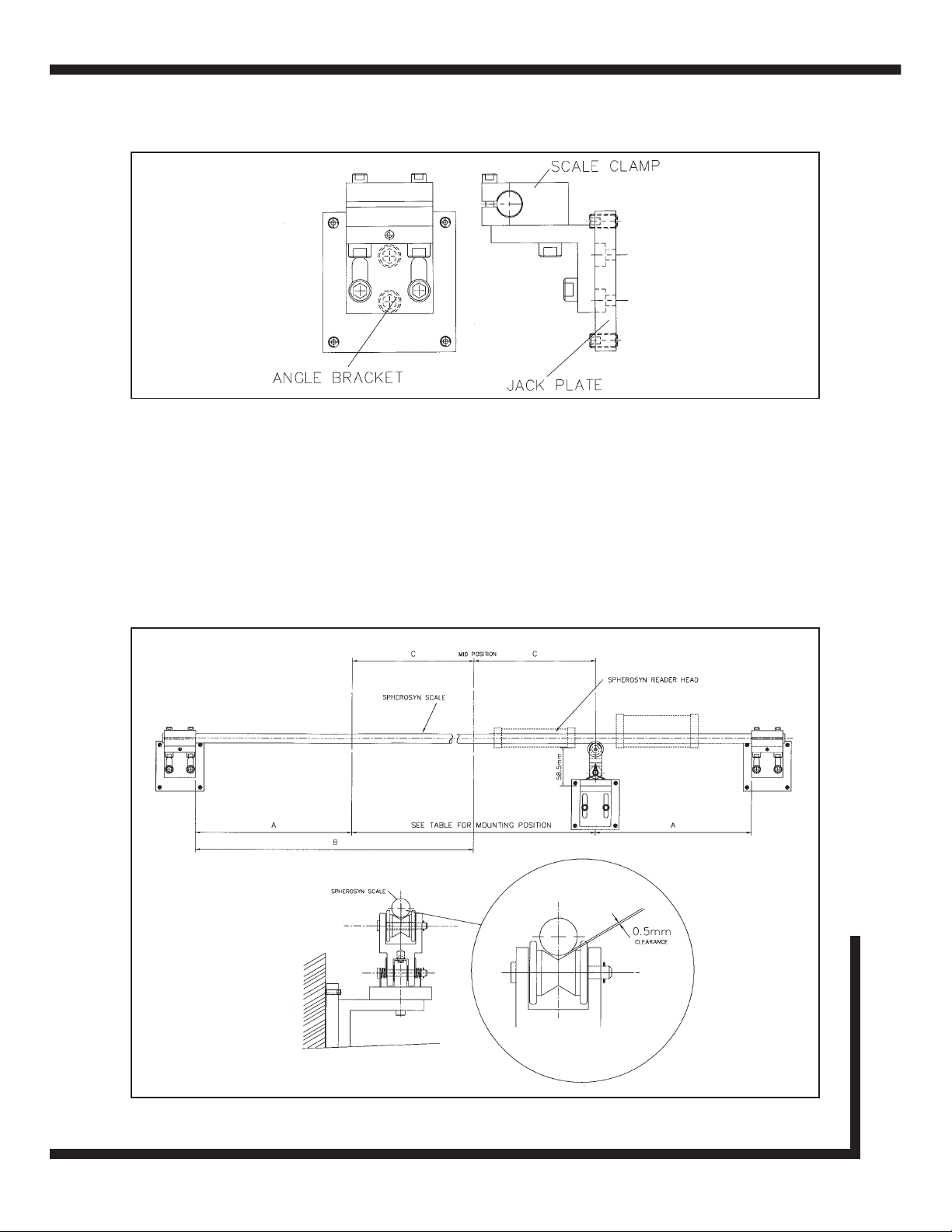
Assemble the angle bracket to the scale clamp (Refer to Figure 4.5). The jack plate is included in each bracket kit and
will only be required if the machine mounting face is not a machined surface. Slide the assembly onto the scale,
allowing approximately 10mm clearance from the end of the reader head.
Mark the position of the jack plate (if required) or the angle support bracket. Drill and tap the necessary fixing holes and
assemble the bracket to the machine.
Remove the blank tube and the bracket assembly from the reader head. Drill and tap M8 x 18mm (USA 5/16 - 18 x
3/4") fixing holes. Fit the jack plate (if required) and secure to the machine. Assemble the scale clamp and the angle
bracket to the jack plate but do not secure. Traverse the reader head as near to the bracket assembly as possible.
Slide the set-up tube through the reader head into the scale clamp. Adjust the brackets into position and carefully
tighten the screws. Check that the set-up tube slides through the reader head and into the scale clamp smoothly
without any fouling or interruption.
Remove the set-up tube and traverse the machine to the full extent in the opposite direction. Remember the “full extent”
is the absolute maximum travel up to the mechanical “dead stops.”
Check the overall length of the actual scale and measure from the outside edge of the scale clamp already fitted to the
machine and mark the position of the scale on to the machine.
Slide the set-up tube into the reader head, assemble the remaining scale bracket assembly including the jacking plate
(if required) and slide onto the tube.
Set the outside edge of the scale clamp level with the mark that indicates the overall length of the scale and mark the
fixing position for the bracket assembly.
58.00
SINGLE END MOUNTING BLOCK
30.00
10.00
25.40
FIXING SLOT FOR M6 SCREW
JACKING SCREWS M5
Figure 4.4 - Single end mounting
Newall Measurement Systems
7
Page 9
Newall Measurement Systems
8
Mounting the Scale
For scales which are mounted in the horizontal position, spring loaded scale supports are included and should be
positioned according to Table 1.
Once the locations for the supports have been determined, the reader head should be positioned in the location where
the first support is to be fitted. Assemble the support unit, including the jack plate if required. Mark the position for the
fixing screws, drill and tap (M8 for the jack plate or M6 for the angle bracket). Ensure that the angle bracket has
sufficient movement utilizing the two slots to allow for adjustment in the vertical plane. It is important that the top face
of the angle bracket is set to 58.5mm (2.3") from the bottom machined face on the reader head.
Figure 4.6 - Long scale mounting and support details
Figure 4.5 - Long scale support bracket assembly
Page 10

Mounting the Scale / Fitting the Scale Guard
Length
2500mm
3000mm
3500mm
4000mm
4500mm
5000mm
5500mm
6000mm
6500mm
7000mm
7500mm
8000mm
8500mm
9000mm
9500mm
10000mm
10500mm
11000mm
No. of Scale
Supports
2
2
2
2
3
3
3
3
4
4
4
4
5
5
5
6
6
6
Left Side (A)
850mm
1100mm
1350mm
1500mm
1125mm
1250mm
1350mm
1500mm
1300mm
1400mm
1500mm
1600mm
1410mm
1500mm
1580mm
1420mm & 2840mm
1500mm & 3000mm
1570mm & 3140mm
Right Side (B)
850mm
1100mm
1350mm
1500mm
1125mm
1250mm
1350mm
1500mm
1300mm
1400mm
1500mm
1600mm
1410mm
1500mm
1580mm
1420mm & 2840mm
1500mm & 3000mm
1570mm & 3140mm
Mid Position
of Travel (B)
-
-
-
-
2250mm
2500mm
2750mm
3000mm
-
-
-
-
4250mm
4500mm
4750mm
-
-
-
Left Side Position
of Travel (C)
-
-
-
-
-
-
-
-
650mm
700mm
750mm
800mm
1410mm
1500mm
1580mm
710mm
750mm
785mm
Right Side Position
of Travel (C)
-
-
-
-
-
-
-
-
650mm
700mm
750mm
800mm
1410mm
1500mm
1580mm
710mm
750mm
785mm
FROM FIXING BRACKET
Table 1
Newall Measurement Systems
9
5.0 FITTING THE SCALE GUARD
Each encoder includes a protective guard. This aluminium guard is intended to protect the scale from impact damage.
The guard can be attached to the machine casting or by means of the scale support pillars (Refer to Figure 5.1).
To fit the guard to the support pillars, measure and mark off the distance between the center of each pillar. For SHG,
drill two 8.5mm (3/8") holes at either end of the guard. The guard can be attached to the pillars by using the button
head screws provided. After the guard is attached, move the machine axis to both extents of its travel ensuring that the
guard does not interfere with or rub against the reader head.
Figure 5.1 - Fitting the scale guard (example shown using a Spherosyn™ scale)
Page 11

Newall Measurement Systems
10
Cable Routing / Final Check
6.0 CABLE ROUTING
The most important and the most over looked aspect of fitting the linear encoder is proper cable routing. Dangling and
loose cables can be snagged or broken causing irreparable damage. Care should be taken in order to ensure that the
cables are secured to the machine and that cable loops do not interfere with any part of the machine or the linear
encoder movements. “P” clips and thread forming screws are provided to route the cables from the reader head.
Note: The armored cable is an integral part of the reader head. If the cable becomes damaged, then it would
have to be replaced complete with the reader head.
If extension cables are used, do not allow the plug and socket junction to lie in the swarf tray or in the direct flow of
coolant or oil. Optional IP67 rated submergible connectors are available if required.
In order to avoid problems associated with electrical noise and interference, do not allow the cables to lie across
electrical motors, fuse boxes or electrical pumps.
7.0 FINAL CHECK
Prior to putting the linear encoder into operation, slowly traverse the machine axis to both extents of its travel checking
at all times that the cables are secure and that machine over travel cannot occur. Newall will not accept responsibility
for linear encoder malfunction caused by over travel or damaged cables.
Page 12

Appendix A
Newall Measurement Systems
11
Appendix A - SCALE BRACKET MOUNTING OPTIONS
Outboard scale support mounting
Scale supports inverted
Page 13

Appendix B
Newall Measurement Systems
12
Appendix B - DIMENSIONAL DRAWING
Page 14

Appendix B (cont’d)
Newall Measurement Systems
13
Appendix B - DIMENSIONAL DRAWING
Page 15

Notes
Newall Measurement Systems
14
Page 16

NEWALL MEASUREMENT SYSTEMS LTD
HEAD OFFICE
Newall Measurement Systems Ltd.
Technology Gateway, Cornwall Road
South Wigston
Leicester LE18 4XH
United Kingdom
Telephone: +44 (0)116 264 2730
Facsimile: +44 (0)116 264 2731
Email: sales@newall.co.uk
Web: www.newall.co.uk
Newall Electronics, Inc.
1778 Dividend Drive
Columbus, OH 43228
Telephone: +1 614 771 0213
Toll Free: 800.229.4376
Facsimile: +1 614 771 0219
Email: sales@newall.com
Web: www.newall.com
023-80620/03-UK . Oct 2006
 Loading...